


Abstract
The reliability of turbopumps in satellite launch vehicles is critically dependent on their structural and thermal responses to severe gradients during the start-up sequence. The primary objective of this research is to perform a comprehensive virtual verification of a turbopump design by simulating these transient operational phases. To achieve this, a sequentially coupled computational framework is established. Initially, computational fluid dynamics and conjugate heat transfer analyses are conducted using fluid properties, turbopump geometry, and flow boundary conditions to extract transient aero/hydrodynamic loads, heat transfer coefficients, and reference temperatures. These thermal boundary conditions, coupled with temperature-dependent material properties, are mapped onto a transient thermal model. Subsequently, a discrete-time finite element analysis is employed to evaluate the temporal behaviour of thermo-mechanical stress states and multi-axis deformations across the assembly. By systematically integrating these analyses, this study quantifies the transient evolution of radial and axial clearances in the critical turbine stage to identify potential rotor–stator interference risks while accounting for conductive thermal coupling across the shaft and pump housings. Results indicate a significant transient reduction in clearance during the initial 12.9% of operation, driven by the differential thermal expansion between the rapidly heating rotor and the cooler stator due to its higher thermal inertia. However, the analysis confirms that a positive gap is consistently maintained even at maximum relative displacement, predicting no radial rotor–stator contact and ensuring the structural and aerodynamic integrity of the turbine stage. Ultimately, these findings provide essential design insights, demonstrating the necessity of holistic modeling in preventing transient failure modes and ensuring the operational safety of next-generation space propulsion systems without relying solely on costly hot-fire tests.
1. Introduction
The propulsion system is the defining subsystem of any space launch vehicle, dictating payload capacity, mission range, and overall reliability. Among the various propulsion cycles utilized in modern rocketry, liquid bi-propellant engines remain the dominant choice due to their high specific impulse and thrust controllability [1]. At the heart of these high-performance engines lies the turbopump assembly (TPA), a rotating machine of exceptional power density tasked with delivering propellants from low-pressure tanks to the combustion chamber at pressures often exceeding 200 bar [2]. The operational environment of a turbopump is characterized by extremes that are rarely encountered in other fields of mechanical engineering: rotational speeds ranging from 5000 to 100,000 RPM, cryogenic fluid temperatures as low as 20 K, and turbine gas temperatures surpassing 1000 K [3,4,5]. Given this harsh operational envelope, it is unsurprising that turbopump malfunctions have historically accounted for a significant percentage of catastrophic launch vehicle failures [4,6]. Consequently, the thermo-mechanical integrity of the TPA is not merely a performance metric but a fundamental constraint for mission success.
In gas-generator cycle engines, the structural complexity is compounded by the compact integration of the pump and turbine. A common shaft typically connects the cryogenic pump impeller and the high-temperature turbine disk, separated by a relatively short axial distance [7,8]. This configuration necessitates robust sealing and thermal isolation strategies to prevent the freezing of bearing lubricants or the overheating of cryogenic seals [9]. While the design of these components for nominal, steady-state operation is a well-established discipline governed by decades of empirical data and standardized codes, the transient phases of operation—specifically the start-up sequence—remain a source of significant engineering risk and uncertainty [10,11].
The start-up transient represents the most dynamic and perilous period in the turbopump’s duty cycle. Within a timeframe often spanning less than one second, the assembly must accelerate from a standstill to its nominal operating speed [12]. This rapid acceleration imposes a sudden and violent thermal shock on the components. As the propellant valves open and the gas generator ignites, the turbine blades and disk are instantaneously exposed to a stream of high-velocity, high-temperature gas [13]. Simultaneously, the pump section is flooded with cryogenic fluid, inducing a rapid chill-down effect. This creates a scenario where the temperature distribution within the assembly is highly non-uniform and transient [14,15]. The rotor components, generally having lower thermal inertia due to their need for low rotational mass, respond relatively quickly to these thermal inputs. In contrast, the casing, housing, and volute structures, which are designed for stiffness and pressure containment, possess significantly higher thermal mass and respond more slowly [16].
This discrepancy in thermal response times, coupled with the immediate onset of intense centrifugal forces, leads to a complex phenomenon known as “transient differential expansion” [17]. The rotor expands radially due to both centrifugal stiffening and thermal growth, while the casing expands primarily due to thermal loads but at a lagging rate. The synchronization—or lack thereof—between the growth of the rotor and the stator defines the evolution of the running clearance (tip clearance) throughout the start-up ramp [18]. Managing this clearance is a critical balancing act in turbomachinery design [19]. On one hand, large clearances are desirable to ensure mechanical safety and prevent contact between rotating and stationary parts. On the other hand, minimized clearances are essential for reducing leakage flows, thereby maximizing the hydraulic and aerodynamic efficiency of the machine [20]. In the context of a rocket engine, where every second of specific impulse translates to kilograms of payload, the pressure to minimize these gaps is immense.
However, if the clearance is designed too aggressively based on steady-state assumptions, the transient differential expansion can lead to “rubbing” events during start-up [21]. Rotor–stator rubbing is a destructive failure mode that can initiate a positive feedback loop known as the Newkirk effect. As the blade tips graze the casing, frictional heat is generated, causing localized thermal expansion at the point of contact [22,23]. This additional expansion intensifies the contact pressure, generating more heat and potentially leading to severe wear, blade fracture, shaft bowing, or rotordynamic instability [24,25]. Furthermore, the debris generated from such interactions can compromise downstream components or block cooling channels, leading to cascading failures [26]. Therefore, the ability to predict the transient evolution of these clearances with high fidelity is a prerequisite for ensuring that the engine can survive the start-up sequence without performance degradation [27].
Despite the criticality of this coupled thermo-mechanical behavior, a comprehensive review of the literature reveals a tendency to analyze the physics in isolation. A substantial volume of research has been dedicated to the fluid dynamics of turbopumps. Studies such as [28,29] have extensively characterized the cavitation performance and hydraulic instabilities of inducers and impellers. Similarly, studies on the aerodynamic optimizations of turbine blades typically assume rigid boundaries and neglect the structural deformations that occur in operation [30].
On the structural analysis front, early analytical methods and simplified numerical models focused primarily on steady-state stresses and rotordynamic critical speeds [31,32]. While these provided a baseline for sizing, they failed to capture the time-dependent nature of the start-up regime. With the advent of advanced computing, transient analyses have become more feasible, yet they often remain compartmentalized. For instance, Abdul-Aziz [10] and Moroz et al. [33] performed detailed transient thermal analyses of turbine rotors, while excluding the influence of the mating shaft and casing. Similarly, He et al. [34] investigated the structural response of cryogenic impellers by employing adiabatic or simplified convective boundary conditions at the component interfaces.
The primary limitation of these component-level studies is the decoupling of the thermal path. In a real turbopump assembly, the heat transfer is not limited to the fluid–solid interaction; there is significant conductive heat flux transferring from the hot turbine disk, through the shaft, towards the cold pump and bearings [35]. The bearing supports and the casing act as thermal bridges that couple the expansion of the hot and cold sections [36]. By isolating the turbine or the pump, the study implicitly assumed that the boundary conditions at the shaft ends are constant or independent, which is an oversimplification during the transient start-up where thermal gradients are most severe [37]. There is a distinct lack of “fully integrated” models that simulate the entire assembly—Turbine, Pump, Shaft, and Casing—as a unified continuum to predict global deformation and clearance evolution [38,39].
To address these shortcomings and bridge the gap between component-level analysis and system-level reliability, this paper presents an integrated thermo-mechanical analysis of a complete turbopump assembly under transient start-up conditions. Unlike previous works that isolate the rotor or stator, this study utilizes a holistic 3D Finite Element Model (FEM) that encompasses the full structural assembly. The analysis employs a coupled scheme where time-dependent thermal boundary conditions, derived from fluid dynamics calculations, drive the structural response. This approach allows for the precise capture of the “thermal lag” between the casing and the rotor, as well as the conductive interaction between the cryogenic and high-temperature domains.
The primary objective of this research is to perform a “Virtual Verification” of the turbopump design [40,41]. By simulating the start-up sequence, this study aims to: (1) quantify the transient evolution of radial and axial running clearances in the high-risk turbine section coupled to the turbopump shafting system; (2) identify potential rotor–stator rubbing and interference risks that would otherwise only be detected during costly hot-fire tests; and (3) evaluate the severe transient thermal gradients and thermo-mechanical deformation mechanisms that govern creep and thermal fatigue susceptibility in uncooled aerospace turbomachinery components [42,43]. The results of this integrated analysis provide essential design insights, demonstrating the necessity of holistic modeling in preventing transient failure modes and ensuring the operational safety of next-generation space propulsion systems [44].
2. Problem Definition
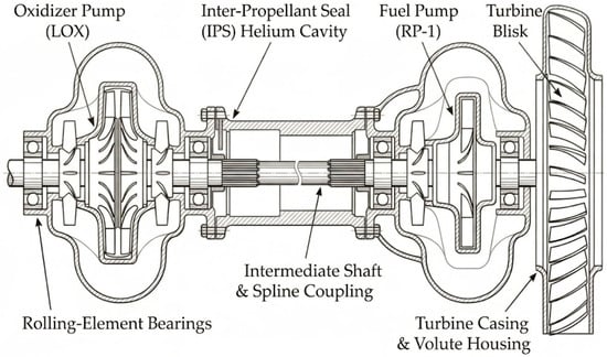
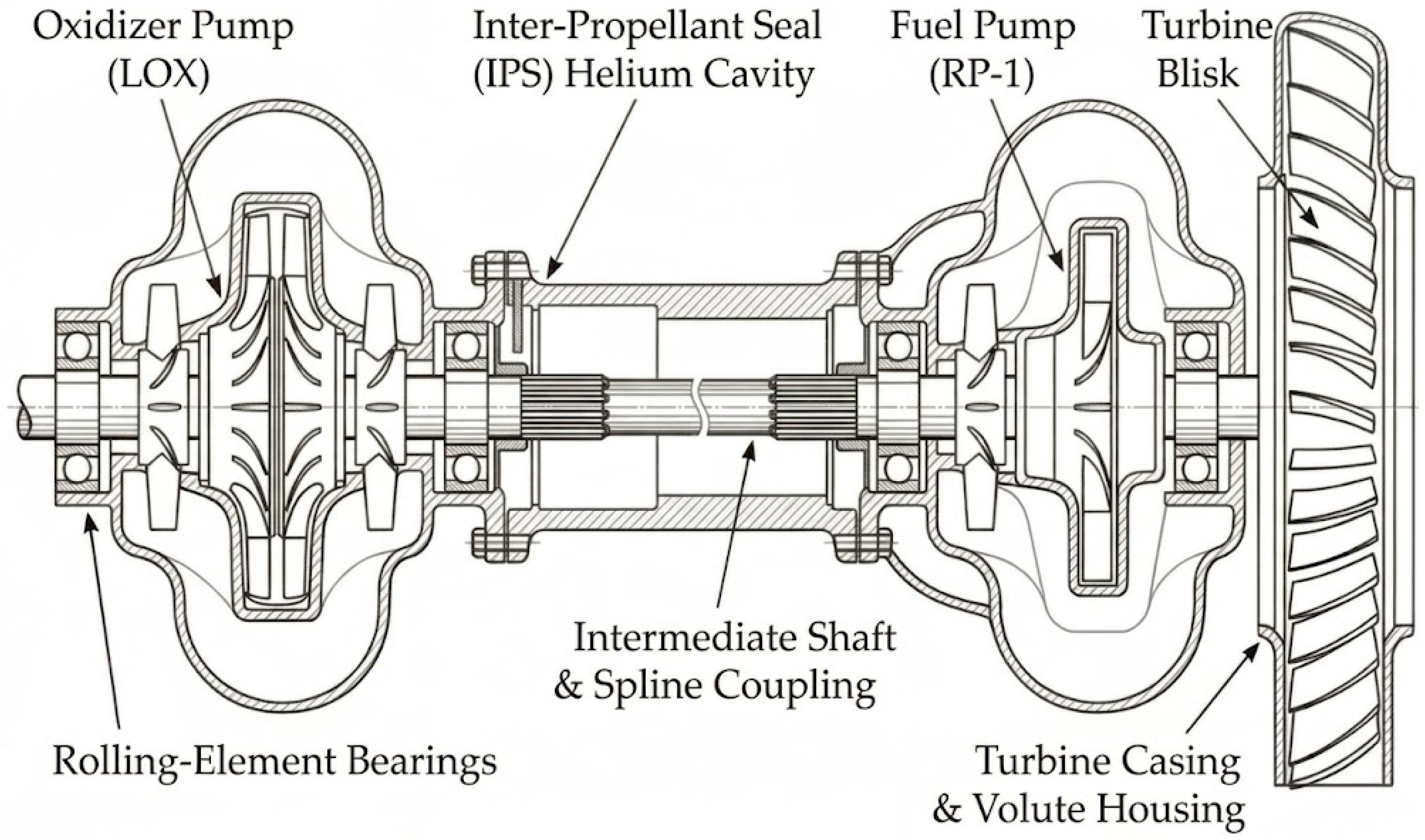
The conceptual baseline architecture and spatial arrangement of the complete turbopump assembly (TPA) are schematically illustrated in Figure 1.
Figure 1.
Turbopump schematic view.
The integrated system comprises three primary functional units: an overhang axial impulse turbine (right) to generate mechanical power, a central fuel centrifugal pump (RP-1), and a cryogenic oxidizer centrifugal pump (LOX, left) to provide the necessary propellant pressurization. The torque generated by the turbine blisk is transmitted to the pump impellers through a coaxial shafting system coupled via a splined intermediate shaft and separated by an inter-propellant seal (IPS) purge housing. While Figure 1 depicts the simplified 2D cross-sectional layout of the internal rotating and stationary components, the 3D computational domain incorporates the actual external dome-shaped turbine exhaust casing, nozzle manifold, and pump housing flanges. In the thermal analysis, conductive and convective heat paths are resolved across the entire TPA (including the oxidizer pump shaft, intermediate shaft, fuel pump housing, and turbine), whereas the high-resolution discrete-time structural clearance assessment specifically focuses on the turbine blisk and stator casing sub-assembly, where thermal shock and differential expansion are most extreme.
The turbopump system employs several working fluids. The cryogenic pump and the fuel pump operate with liquid oxygen (LOX) and RP-1, respectively. The turbine is driven by hot combustion gases produced in the gas generator. Helium is used in the inter-propellant seal region to maintain an inert atmosphere. Table 1 lists the thermophysical properties that were utilized during the design stage.
Table 1.
Thermophysical properties of the fluids in the turbopump system.
The turbopump assembly incorporates a variety of materials selected to meet specific performance criteria. Certain components require materials with high mechanical strength to withstand elevated temperatures, while others are chosen for their sealing capabilities. In regions where only modest mechanical loads are present, cost-effective materials with lower strength requirements are employed. Because material properties vary significantly across cryogenic (95 K) and high-temperature combustion gas (>1000 K) regimes, full temperature-dependent property curves, specifically for thermal conductivity , specific heat , elastic modulus , yield strength, and thermal expansion coefficient , are implemented in the numerical solver. Table 2 summarizes the baseline reference material properties at ambient temperature (298.15 K) applied prior to thermal interpolation during the analysis phase.
Table 2.
Thermophysical properties of the solids in the turbopump system.
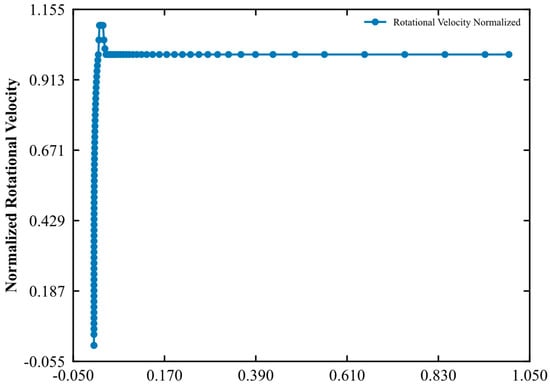
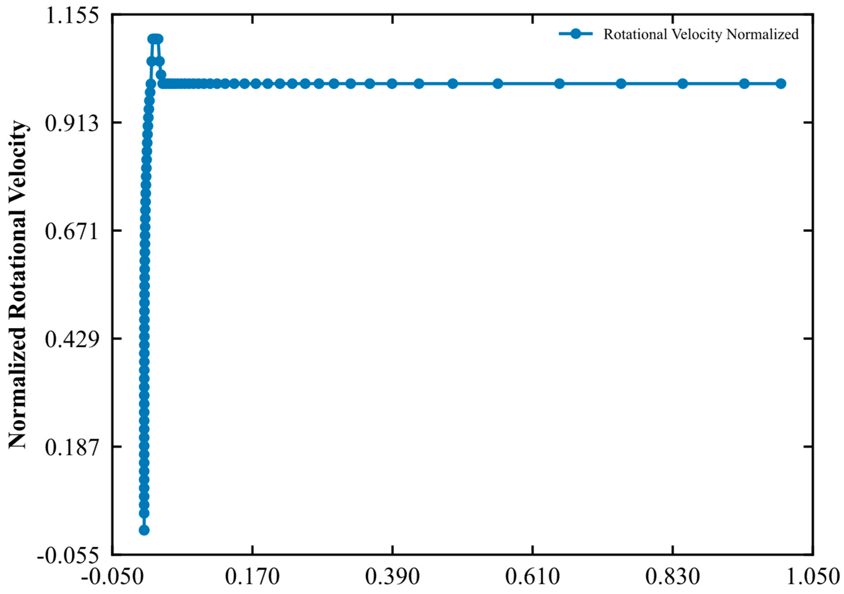
The normalized transient rotational speed profile () of the turbopump assembly during the liftoff phase is illustrated in Figure 2 as a function of normalized operational time (). A detailed quantitative examination of Figure 2 reveals three distinct dynamic regimes that govern the mechanical loading history of the rotor:
Figure 2.
Rotational speed profile of turbopump as a function of time.
- Rapid Ignition Ramp-Up (): Immediately following gas generator ignition and propellant valve opening, the rotating assembly accelerates from standstill to 100% nominal rotational speed within the first 2.5% of the operational timeframe. This extreme angular acceleration () imposes abrupt torsional and centrifugal inertial loads while the structural housing remains near ambient temperature.
- Transient Rotational Overshoot (): Before the closed-loop propellant control system and pump discharge pressure fully stabilize the resistive hydraulic torque, the rotor experiences a pronounced rotational speed overshoot, peaking at a normalized velocity of 1.105 (a 10.5% overshoot above nominal speed) at . Because centrifugal body forces scale quadratically with angular velocity (), this 10.5% speed excursion generates a temporary 22.1% surge in centrifugal stress and radial elastic growth during the exact operational period when the turbine blade tips undergo severe thermal shock.
- Quasi-Steady Rotational Plateau (): Following the initial surge, the rotational speed rapidly damped and settles at the nominal operating plateau () for the remainder of the mission profile ( to ). Crucially, while mechanical rotational equilibrium is achieved within just 4% of the operational period, the thermal field continues to evolve over a much longer timescale, creating a decoupled thermo-mechanical lag between centrifugal and thermal expansions.
The operational environment of a rocket engine turbopump during the liftoff sequence is characterized by a complex interplay of extreme mechanical and thermal loading conditions. In addition to the significant inertial centrifugal forces arising from high rotational speeds, the structural integrity of the assembly is challenged by intense pressure gradients across the pump and turbine stages. Simultaneously, the turbine section is exposed to high-temperature combustion gases emanating from the gas generator, inducing severe thermal gradients within the material.
During this transient phase, these thermal loads evolve into time-dependent temperature fields, which in turn generate thermal stresses that fluctuate in both magnitude and orientation as the system reaches its nominal operating state. Modeling this coupled thermomechanical behavior presents substantial challenges due to the high-gradient nature of the startup sequence and the non-linear response of the materials involved.
A review of the existing literature reveals a critical gap; many studies rely on steady-state approximations or decoupled analyses, often overlooking the intricate, time-varying stress states that occur during the initial seconds of flight. This study aims to address this deficiency by providing a high-fidelity, transient thermomechanical model that accounts for the simultaneous evolution of mechanical and thermal loads, thereby ensuring a more accurate prediction of structural reliability under flight conditions.
3. Methodology
3.1. Computational Framework of the Fluid Domain
In this study, the fluid flow within the pump is considered three-dimensional, unsteady, incompressible, and turbulent. To resolve the turbulent flow characteristics, the Reynolds-Averaged Navier–Stokes turbulence model is employed. The exact conservation equations for mass, momentum, and energy in the fluid domain are expressed using Cartesian tensor notation. For an incompressible fluid, the density is constant, yielding a divergence-free velocity field as in Equation (1):
The conservation of momentum for the turbulent flow field incorporates the Reynolds stresses to account for turbulent velocity fluctuations. Furthermore, due to the rotational nature of the pump impeller, Equation (2) is formulated in a rotating reference frame, introducing Coriolis and centrifugal body forces:
In this formulation, is the time-averaged velocity component, is the time-averaged static pressure, and is the dynamic viscosity of the fluid. The Reynolds stress tensor, defined as , is closed using the turbulence model. The term represents the momentum source terms resulting from the rotating frame of reference at an angular velocity , defined as in Equation (3):
The fully coupled energy equation for the fluid domain accounts for unsteady thermal transport, convective heat transfer, and turbulent thermal diffusion as in Equation (4). To capture aerodynamic and hydrodynamic heating in the high-shear boundary layers typical of turbomachinery, the total viscous dissipation term is strictly retained.
Here, is the specific heat capacity of the fluid, is the time-averaged fluid temperature, is the molecular thermal conductivity, is the turbulent eddy viscosity, and is the turbulent Prandtl number. The total viscous dissipation term including mean flow dissipation and the turbulent dissipation is defined in Equation (5):
For the solid components of the pump, including the impeller, volute casing, and shaft, the macroscopic velocity field is zero . Consequently, the conservation of energy reduces to the three-dimensional unsteady heat conduction equation as expressed in Equation (6), which accommodates potential internal heat generation from frictional or electrical sources:
Here, , , and denote the density, specific heat capacity, and thermal conductivity of the solid material, respectively. To ensure a physically consistent solution, the fluid and solid computational domains are robustly coupled at the fluid–solid interfaces . Assuming perfect thermal contact with no resistance, the continuity of both temperature (Dirichlet condition, Equation (7)) and local conductive heat flux (Neumann condition, Equation (8)) is strictly enforced:
In these boundary conditions, denotes the unit normal vector outward from the interface, completing the conjugate heat transfer framework.
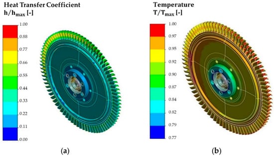
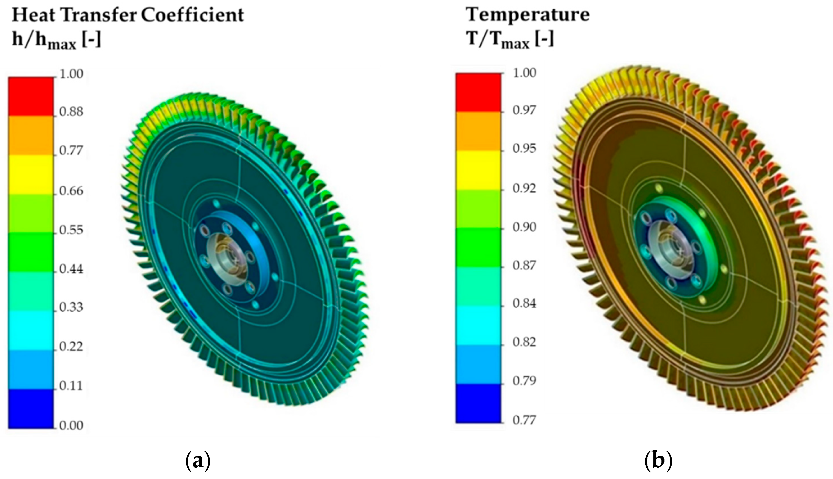
Within the sequentially coupled multiphysics architecture, the fluid–thermal interaction is resolved in two consecutive stages to balance computational tractability with high spatial fidelity. In stage 1, a three-dimensional steady-state Conjugate Heat Transfer (CHT) simulation is executed at nominal operating conditions using the turbulence model (Equations (1)–(8)). The fluid domains encompass the hot gas generator combustion products entering the turbine nozzle manifold, the cryogenic LOX flow in the oxidizer pump, the RP-1 flow in the fuel pump, and the pressurized helium purge gas inside the inter-propellant seal cavity (fluid properties defined in Table 1). From the converged stage 1 CHT solution, spatially varying convective heat transfer coefficients h (x,y,z), adiabatic wall reference temperatures , and static pressure fields p (x,y,z) are extracted across all wetted fluid–solid interfaces . In stage 2, these extracted spatial profiles are mapped via 3D Nearest-Neighbor surface interpolation onto the solid finite element mesh as Cauchy (convective) boundary conditions to drive the full-assembly transient conduction analysis (Equation (6)). At each wetted surface node, the instantaneous convective heat flux is dynamically computed by the transient solver according to Newton’s Law of Cooling, , where is the time-varying solid surface temperature. Figure 3a,b illustrate the mapped spatial distributions of the normalized convective heat transfer coefficient () and normalized reference fluid temperature (, scaled by the turbine inlet temperature ) on the turbine blisk, respectively.
Figure 3.
Thermal boundary conditions of turbine blisk: (a) heat transfer coefficient and (b) reference temperature.
High heat transfer coefficients are concentrated along the blade leading edges and pressure surfaces due to boundary layer thinning and high relative gas velocities, whereas lower values occur in the hub and bolted shaft interface regions. A quantitative summary of the extracted thermal boundary parameters across all primary sub-domains of the TPA is provided in Table 3.
Table 3.
Summary of normalized convective thermal boundary parameters extracted from stage 1 CHT analysis and mapped to the stage 2 transient thermal FEA model.
In addition to internal working fluid interactions, exterior surfaces which are not in contact with internal flows are modeled as an uninsulated configuration exposed to ambient natural convection. Furthermore, the role of internal energy sinks is explicitly considered in the thermal network. As highlighted in cryogenic turbopump chill-down and bearing cavity studies by Joseph et al. [14] and Saraf et al. [15], propellant-lubricated bearings and seal purge flows act as localized heat sinks that extract thermal energy conducted down the shaft from the hot turbine overhang. In the present model, the cryogenic LOX domain, the RP-1 fuel domain, and the continuous helium purge serve as the primary macroscopic energy sinks arresting heat propagation along the rotor shaft and casing flanges. Secondary micro-scale heat losses associated with bearing lubricant film evaporation and localized frictional dissipation in the rolling elements are neglected in the global turbine casing model. From a thermo-mechanical design perspective, omitting secondary lubricant heat extraction in the immediate vicinity of the turbine overhang represents a deliberately conservative assumption: it yields slightly higher predicted temperatures in the turbine disk hub and overhang shaft, thereby maximizing the predicted radial thermal expansion of the rotor and providing an upper-bound (worst-case) safety evaluation against rotor–stator tip rubbing.
3.2. Computational Framework of the Structural Domain
To evaluate the structural response at critical transient moments, the principle of static equilibrium is applied to the solid domain at each discrete time step. The governing equation for the stress field within the turbopump assembly is described in Equation (9):
where is the Cauchy stress tensor and denotes the body forces per unit volume, primarily comprising centrifugal loads in this application. Given the pronounced deformations inherent in high-speed rotating components, a large-strain framework is adopted to account for geometric nonlinearities. The motion is characterized by the deformation gradient tensor, F = ∂x/∂X, which is decomposed via right polar decomposition (F = RU) to isolate the right stretch tensor U from rigid-body rotation R. Consequently, the logarithmic (Hencky) strain measure, ε = ln(U), is employed to provide an objective description of strain consistent with incremental constitutive updates.
For inelastic material behavior, the solution is obtained through an incremental framework. The total logarithmic strain is evaluated as , where the increment is computed using a midpoint configuration. This approach minimizes the influence of rigid-body rotation and enhances numerical accuracy during complex loading cycles.
The thermomechanical nature of the assembly requires the integration of thermal effects into the strain field. Consistent with the finite-strain formulation, the logarithmic thermal strain is defined in Equation (10):
where is the coefficient of thermal expansion. This formulation leads to the updated length relation , ensuring compatibility between thermal expansion and the large-strain kinematics.
Material nonlinearity is represented using a multilinear kinematic hardening model, which is particularly effective for capturing the Bauschinger effect and path-dependent plastic evolution in aerospace alloys. The model utilizes a subvolume (overlay) approach where the uniaxial stress–strain curve is divided into segments. The overall plastic response is obtained by the weighted summation of individual subvolume increments as shown in Equation (11):
This integrated framework, coupling large-strain kinematics with a multilinear hardening law, provides a robust basis for capturing the synergistic effects of geometric rotation, thermal gradients, and material yielding under severe transient conditions.
Since the structural acoustic wave propagation times in metallic rotors are several orders of magnitude shorter than the thermal diffusion timescale, the transient thermo-structural response during start-up is governed by a sequence of quasi-static mechanical equilibria (Equation (9)) driven by time-dependent boundary loads. Rather than applying a single static load or executing a prohibitive full-transient elastodynamic integration over millions of degrees of freedom, a discrete-time quasi-static structural coupling strategy is implemented across discrete time steps () spanning the normalized operational window. At each discrete time step, three synchronized load sets are simultaneously applied to the finite element domain:
- Time-Dependent Inertial Body Loads: The instantaneous angular velocity is extracted directly from the transient start-up speed profile in Figure 2 and applied to the rotating assembly to generate the exact centrifugal body force vector .
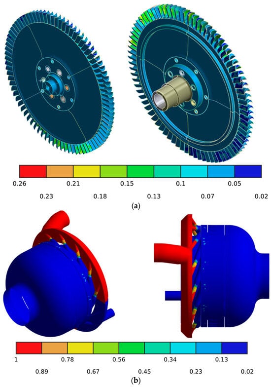
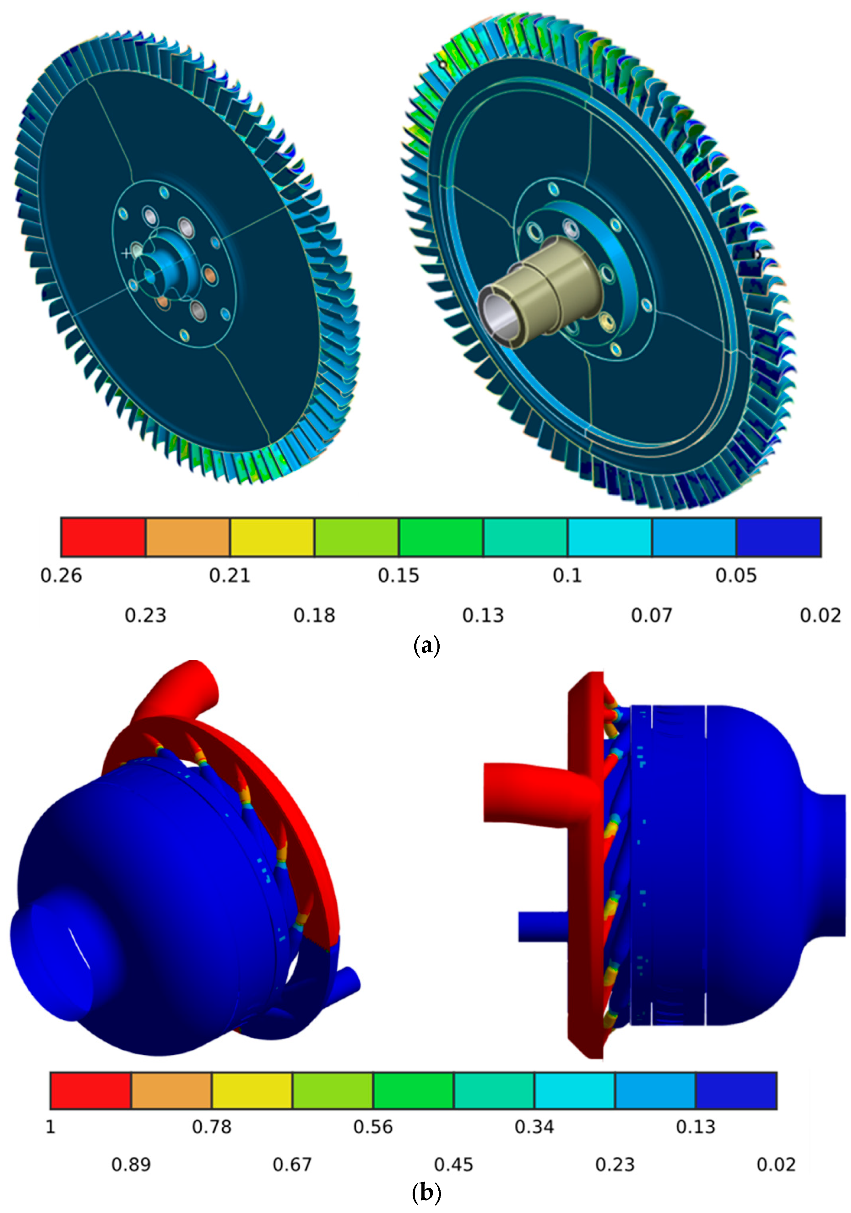
- Fluid-Dynamic Surface Pressure Loads: The spatial aerodynamic and hydrodynamic static pressure distributions extracted from the stage 1 CFD simulation are mapped as normal surface tractions onto the wetted rotor and stator surfaces (shown in normalized form in Figure 4a for the turbine blisk and 4b for the turbine casing flow path), scaled dynamically with the pump/turbine operating head at step .Figure 4. Representation of mechanical loading conditions on (a) spatial distribution of gas pressure loads applied to the turbine blisk and (b) spatial distribution of gas pressure loads applied to the turbine casing flow path.
- Transient Thermal Body Loads: The three-dimensional nodal temperature field computed by the stage 2 transient thermal FEA is imported directly into the structural mesh to induce inhomogeneous thermal strains via Equation (10).
To simulate physical bearing supports without artificially over-constraining radial thermal growth at the disk–shaft interface, cylindrical constraints are applied at the bearing journal locations, permitting rotational freedom while restraining rigid-body axial translation.
Nonlinear contact formulations were employed to simulate the structural interaction at the turbine-to-shaft interference fit, allowing for a precise calculation of contact pressures and potential sliding. For the stator assembly, a fixed boundary condition was applied to the end of pump housing. This location was selected to ensure that the constraints remained sufficiently remote from the critical regions of interest, thereby preventing artificial influence on the stress and displacement distributions within the primary stator components. To capture the effects of large deflections and stress stiffening resulting from high-speed rotation, geometric nonlinearities (NLGEOM) were activated during the iterative solution phase.
3.3. Computational Framework of Multiphysics
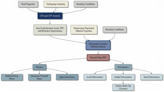
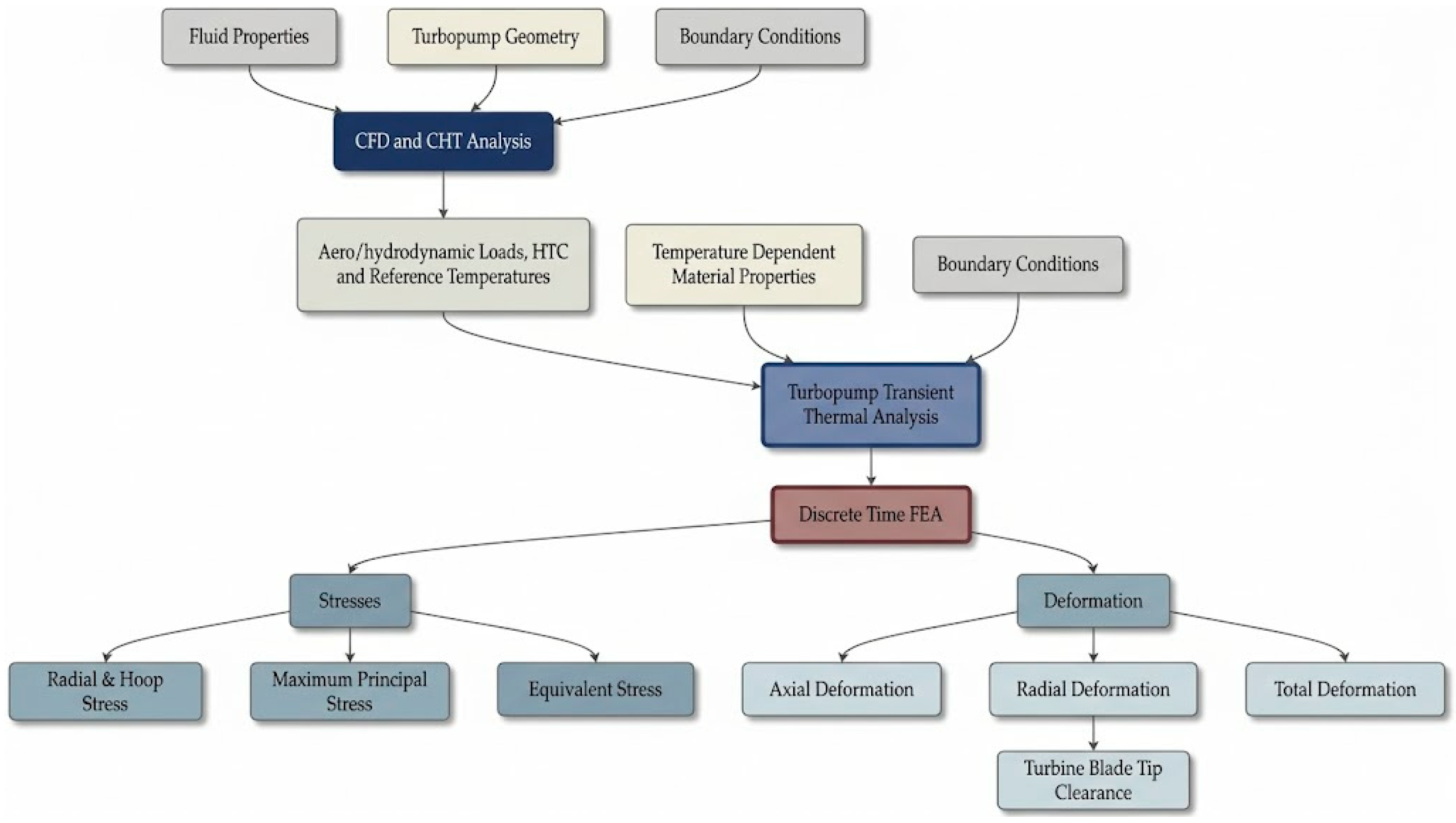
Evaluating the structural integrity and operational efficiency of a turbopump requires a highly targeted, sequentially coupled multiphysics workflow. The process initiates with combined computational fluid dynamics and conjugate heat transfer analyses to accurately resolve both fluid dynamics and severe thermal interactions at the fluid–solid interface. From these initial analyses, detailed surface heat transfer profiles and hydrodynamic pressure loads are extracted. Subsequently, the CHT results are mapped as boundary conditions onto a solid mesh for a transient thermal finite element analysis, which calculates the time-dependent internal temperature gradients and thermal lag throughout the system’s geometry. Rather than executing a computationally expensive full transient structural simulation, the resulting thermal history is systematically analyzed to isolate specific, critical discrete time steps where transient conditions are most severe. At these carefully selected intervals, individual static structural analyses are performed by simultaneously applying the corresponding nodal temperature fields as thermal body loads and the CFD-derived pressure distributions as mechanical surface loads. Properly accounting for combined thermo-mechanical forces, this targeted structural phase yields key localized metrics, including equivalent (von Mises) stresses, maximum principal stresses, and total directional deformations. Ultimately, extracting these precise deformation outputs at critical transient moments is vital for predicting dynamic system clearances. As a prime example, this exact methodology is strictly required to determine final turbine blade tip clearances under peak operational loads, thereby ensuring optimized aerodynamic efficiency while preventing catastrophic physical rubbing within the structural casing.
Figure 5 illustrates the integrated simulation procedure, beginning with the definition of fluid properties and turbopump geometry for combined CFD and CHT analyses. It details the extraction of hydrodynamic and thermal loads which serve as inputs for the transient thermal FEA, accounting for temperature-dependent material properties. The final stages involve discrete-time structural analyses to evaluate critical stress states and deformations, ultimately facilitating the precise prediction of turbine blade tip clearances during transient operational phases.
Figure 5.
Computational workflow of the sequentially coupled multiphysics analysis.
3.4. Finite Element Domain Discretization
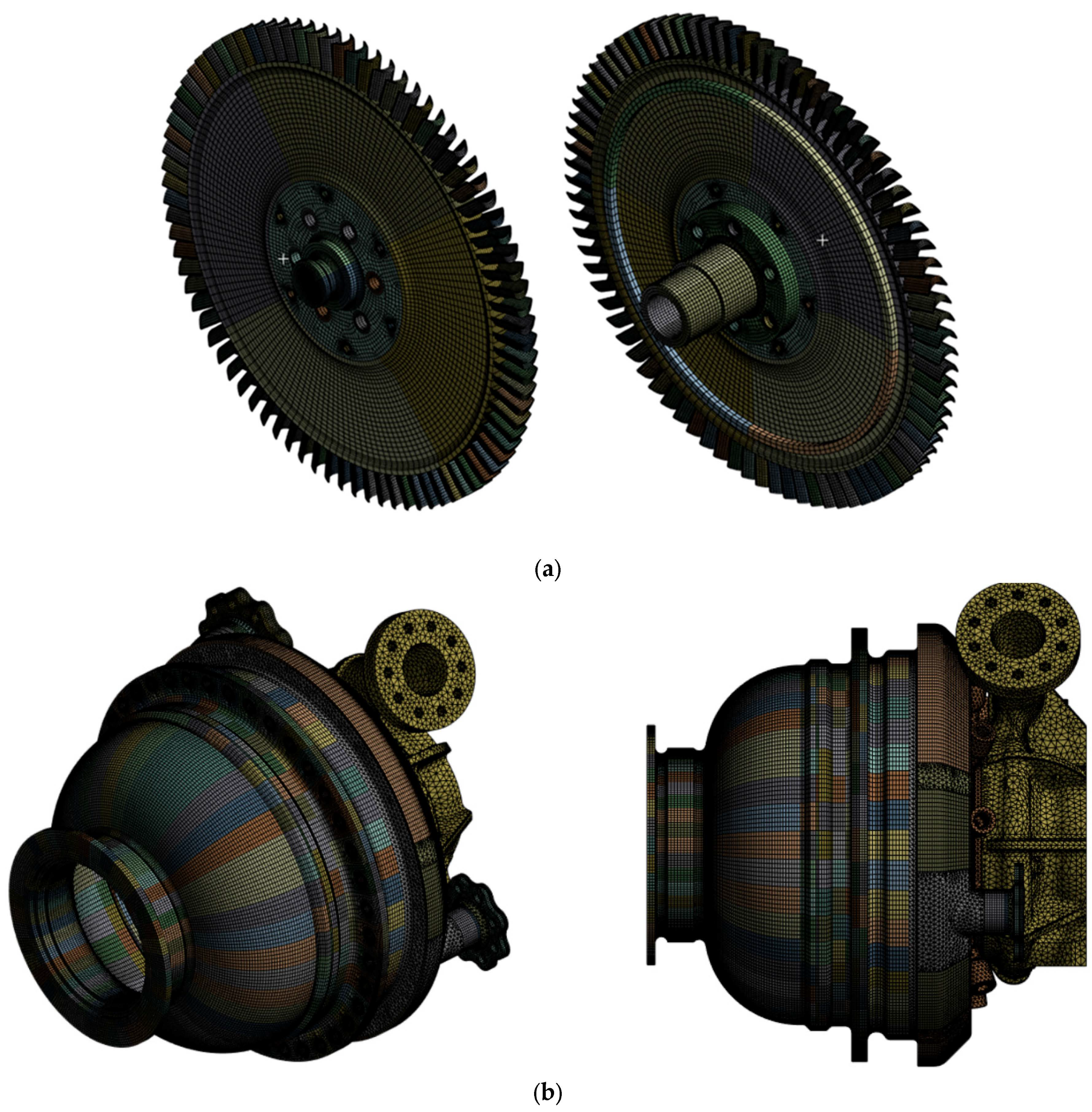
The turbine blisk and shaft assembly were discretized using eight-node hexahedral SOLID185 elements within the ANSYS Workbench 2025 R2 environment, utilizing a high-density structured mesh to capture steep local thermal and stress gradients. Following a systematic grid refinement study, the production mesh (Mesh N2) for the rotating turbine-shaft assembly consisted of 152,904 elements (194,336 nodes). To account for nonlinear material behavior under high structural loads, a multilinear elasto-plastic constitutive model was assigned to all rotor components. The assembly is manufactured from Inconel 718 (AMS 5663) (TEI Alloys Inc., Izmir, Türkiye) bar stock, a nickel-based superalloy selected for its high-strength properties at elevated temperatures. Given that the turbine is subjected to high-temperature discharge from the gas generator, temperature-dependent material properties were implemented to accurately reflect the varying thermal environment across the turbine and shaft interface.
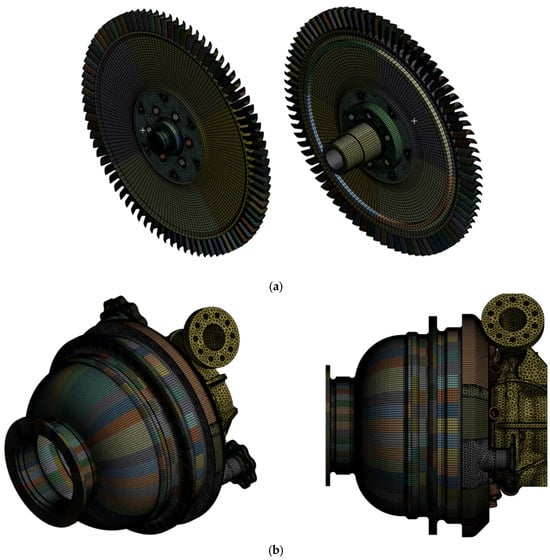
In addition to the rotor assembly, the stationary components of the turbine, including the pump housing, were incorporated into the finite element model. The stator geometry was discretized primarily using a combination of SOLID185 (eight-node hexahedral) and SOLID187 (ten-node tetrahedral) elements. The resulting mesh for the stationary assembly consisted of 1,350,312 elements and 1,926,407 nodes, providing the mesh resolution necessary to capture complex geometric features and local stress concentrations. The visual representation of finite element mesh of turbine rotor and stator is shown in Figure 6a,b, respectively.
Figure 6.
Finite element discretization of (a) turbine rotor and (b) turbine stator.
To strictly guarantee numerical convergence and ensure that the predicted tip clearances are independent of spatial discretization, a four-level mesh-independence study (Meshes N1 through N4) was conducted on the turbine rotor assembly under peak thermo-mechanical loading. As summarized in Table 4, the normalized blade tip radial displacement exhibits a noticeable variation of 1.14% between the coarse mesh N1 and the medium-fine mesh N2, indicating that N1 is insufficient to resolve the steep radial thermal gradient across the blade root. However, further refinement to N3 and N4 yields negligible deviations of only 0.018% and 0.027%, respectively, confirming that the numerical solution achieves asymptotic mesh independence at level N2. Consequently, Mesh N2 was selected for all subsequent multi-step simulations to ensure high numerical fidelity at an optimal computational cost.
Table 4.
Mesh convergence history.
4. Results and Discussion
4.1. Thermal Analysis Results
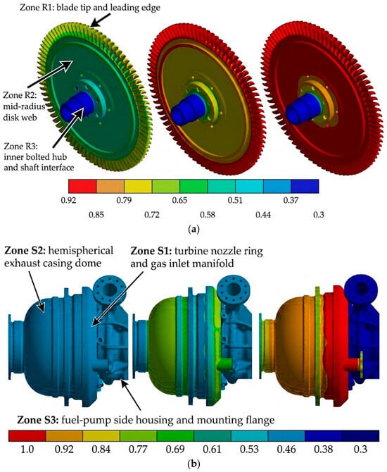
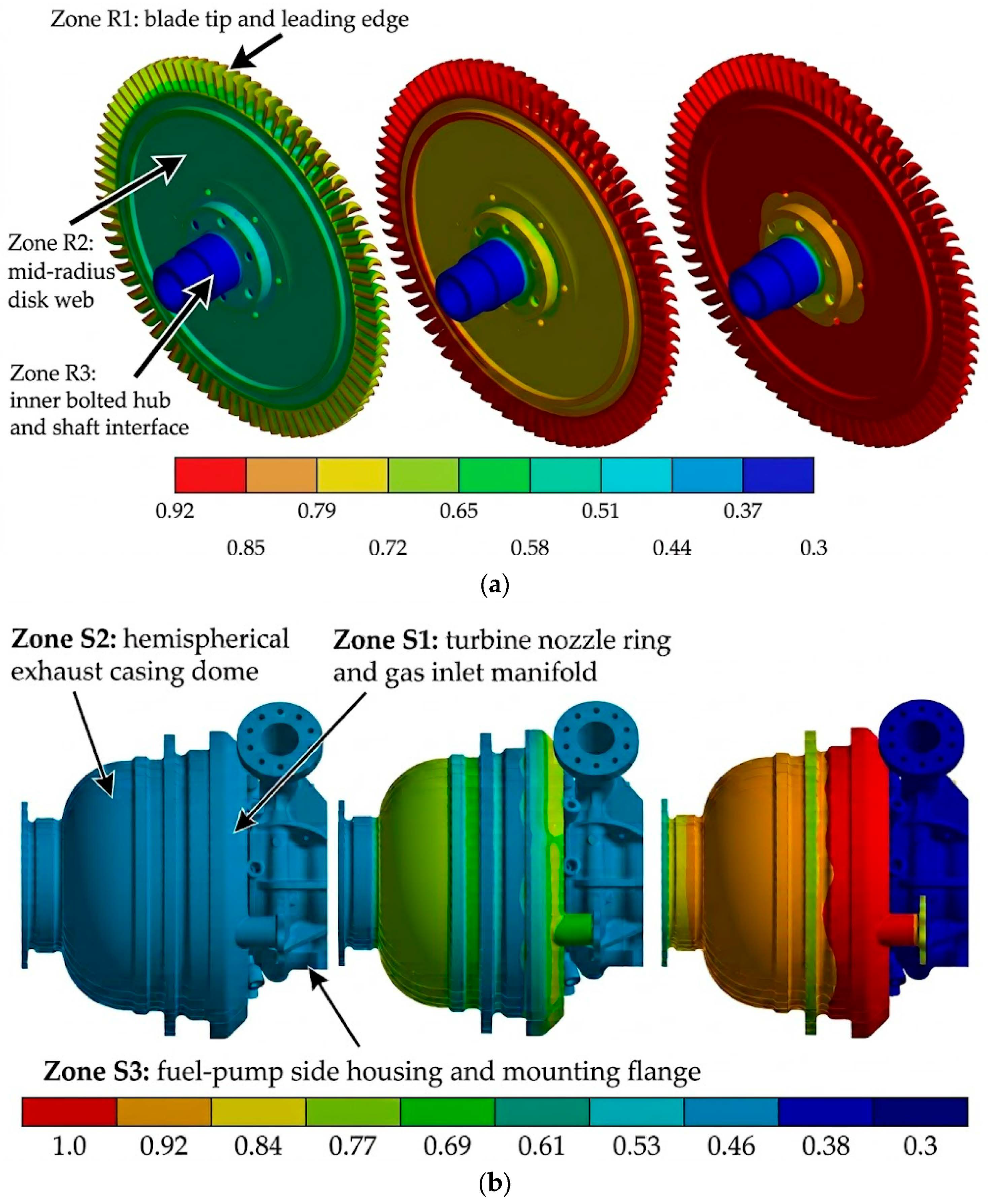
The most critical thermal region in the rotating assembly is the uncooled turbine blisk, where sudden exposure to combustion gases induces severe spatial temperature gradients during ignition. To systematically quantify the spatial and temporal progression of the thermal wave—adopting a zone-based tracking methodology analogous to the structural node monitoring in Section 4.2—three distinct radial zones on the rotor (Zone R1: blade tip and leading edge; Zone R2: mid-radius disk web; Zone R3: inner bolted hub and shaft interface) and three axial/radial zones on the stator (Zone S1: turbine nozzle ring and gas inlet manifold; Zone S2: hemispherical exhaust casing dome; Zone S3: fuel-pump side housing and mounting flange) are evaluated across three normalized time steps: (immediate post-ignition shock), (peak rotational overshoot regime), and (end of operational period). The temperature distributions () and the corresponding zones are illustrated in Figure 7a,b.
Figure 7.
Dimensionless temperature distribution of (a) blisk and (b) casing for , and from left to right.
At the initial thermal shock stage, a steep radial temperature gradient develops across the blisk. Due to the high surface-area-to-volume ratio of the thin blades and the elevated convective heat transfer coefficients (), Zone R1 heats up almost instantaneously to , whereas the massive disk web (Zone R2) and inner hub (Zone R3) remain near their initial ambient state (). At , Zone R1 reaches an asymptotic thermal plateau corresponding to , meanwhile radial conduction gradually heats Zone R2, bringing its temperature to . However, Zone R3 at the shaft interface remains thermally lagged at , creating a maximum radial temperature differential () across the disk radius. At , thermal diffusion saturates the entire disk web (Zone R2 reaches ), while Zone R3 stabilizes between 0.30 and 0.79 due to continuous conductive heat extraction toward the cooler fuel-pump shaft.
A starkly different transient response is observed in the stationary assembly in Figure 7b. At , the entire external casing (Zones S1–S3) remains virtually uniform at ambient temperature (), as the internal thermal wave has not yet penetrated the thick casing walls. At , the high-velocity gas jet heats the internal nozzle ring and inlet manifold (Zone S1) rapidly up to internally (manifesting as on the outer manifold wall), while the exhaust dome (Zone S2) reaches only and the fuel-pump housing (Zone S3) remains entirely cold (). Even at the end of the operational period (), while Zone S1 becomes fully saturated () and the dome (Zone S2) reaches , the massive stator assembly as a whole never achieves complete thermal equilibrium due to its high thermal mass and flanged interfaces. Zone S3 (fuel pump housing) remains at approximately , acting as an effective thermal sink that absorbs conductive heat flux from the turbine casing flange, while localized heating is transferred toward the oxidizer pump housing across the inter-propellant seal region. Globally, thermal steady-state is achieved at approximately of the operational period for the cryogenic oxidizer-pump shaft, for the fuel-pump shaft, for the intermediate shaft, and for the rotating assembly, closely corroborating the multi-component thermal lag mechanisms reported by Roman and Turner [16] and Yoo et al. [37].
From a structural durability standpoint, the rapid heating of the uncooled turbine blades (Zone R1) to within has profound implications for thermal stress evolution and creep susceptibility. During the initial transient ( to ), the rapidly expanding outer blade rim (Zone R1) is radially constrained by the cooler, stiffer inner disk web (Zone R2) and hub (Zone R3), inducing severe compressive hoop stresses at the blade tips and tensile radial stresses at the web-to-hub transition. Since the turbine blades are uncooled, sustained operation at leads the Inconel 718 superalloy into a regime where elastic modulus and yield strength degrade noticeably, and time-dependent viscoplastic creep deformation—combined with low-cycle thermal fatigue—becomes a primary life-limiting mechanism [10,13,42]. While the short duration of a single launch start-up transient prevents immediate creep rupture during liftoff, cumulative creep elongation of the uncooled blades over full-duration hot-fire missions or reusable engine cycles can permanently reduce the running tip clearance and lead to catastrophic blade-casing interference if not accounted for in the initial cold clearance budget [26,43].
4.2. Structural Analysis Results
The structural investigation focuses on the time-dependent radial and axial deformations of both the turbine blisk blade tip and the stator casing structure. By synthesizing these individual displacement profiles, the evolution of the net operational clearance between the blisk and the casing is determined throughout the transient regime. Tracking this dynamic clearance is critical for validating the system’s structural integrity, as it ensures optimized aerodynamic performance while preventing potential mechanical interference between the rotating and stationary components under peak operational loads. At each discrete time step, the synchronized rotational inertial loads, aerodynamic surface pressures, and transient nodal temperature distributions were simultaneously applied to the structural rotor and stator assemblies.
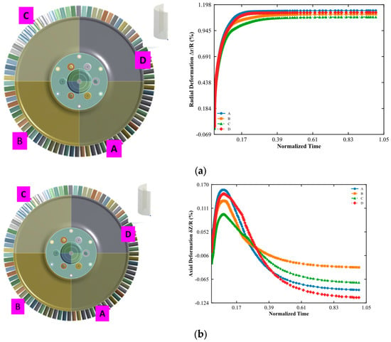
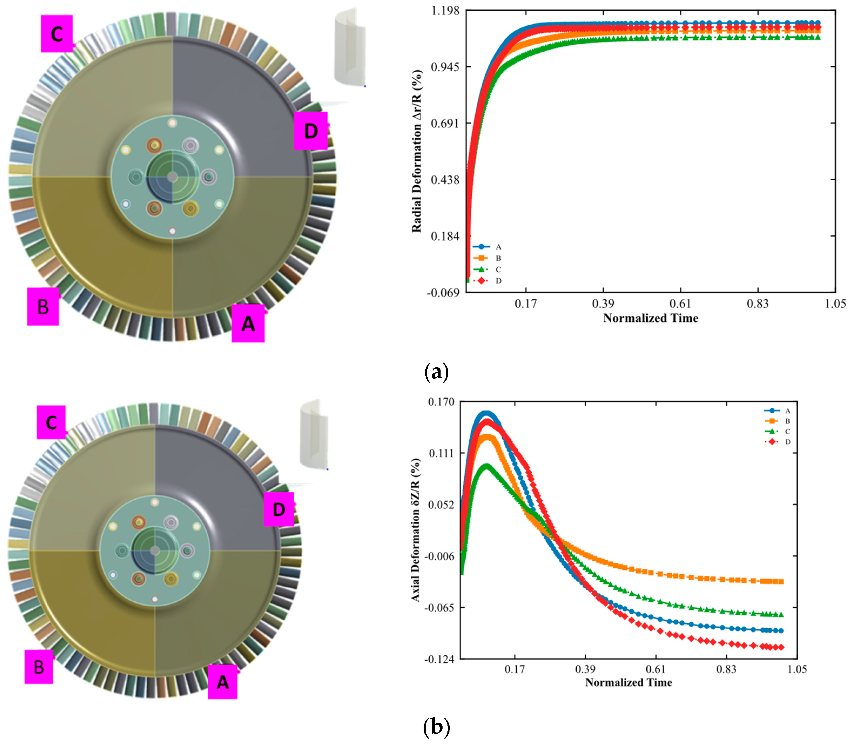
The transient radial and axial displacement histories of four circumferential monitoring nodes (A, B, C, and D, spaced at intervals) at the turbine blisk blade tip are illustrated in Figure 8a,b, respectively. These deformations are critical as they directly dictate the operational rotor–stator clearance and overall aerodynamic efficiency.
Figure 8.
Transient deformation histories of the blisk blade tip: (a) radial deformation dominated by thermal expansion; (b) axial deformation showing transient bending effects.
As shown in Figure 8a, the normalized radial displacement of the blisk reaches a quasi-steady plateau after approximately 26% of the operational period, attaining a maximum value of 1.14% at node A. To rigorously verify the accuracy of the finite element structural model, an independent analytical thermo-elastic verification was performed by decomposing the total blade tip radial growth into its thermal expansion () and centrifugal mechanical () components. For a disk with inner radius and outer radius subjected to a radial temperature distribution , the theoretical radial thermal displacement is governed by Equation (12):
Given the steady-state peak blisk temperature of and the corresponding high-temperature thermal expansion coefficient of Inconel 718 at operating temperature, interpolated from the baseline ambient value of in Table 2), the analytical thermal growth evaluated via Equation (12) yields . Superimposing the analytical elastic radial growth induced by centrifugal body forces on a rotating disk at nominal speed, , yields a combined theoretical radial expansion of 1.133%. This analytical benchmark shows exceptional agreement with the 3D FEA prediction of 1.140% with a relative error of only 0.61% attributable to 3D blade-root stiffening and bolted hub constraints. This serves as a direct analytical validation of the computational thermo-mechanical model, confirming that approximately 92% of the total radial growth arises from thermal expansion, while the remaining ~8% results from centrifugal loading.
Regarding the axial response presented in Figure 8b, the blisk exhibits a pronounced dual-phase axial bending behavior. Initially (), rapid convective heating of the rear disk face and blade platform relative to the cooler front hub face generates an axial thermal moment that bends the blisk toward the nozzle side, reaching a positive peak axial displacement of at node A. However, as heat conducts through the disk thickness and the axial temperature gradient diminishes (), the bending direction reverses toward the exhaust side, stabilizing at a negative axial displacement of . This non-monotonic axial thermal bowing closely matches the transient disk-bending physics reported in liquid rocket engine turbopump turbines by Yoo et al. [37] and Hong et al. [41], further verifying the physical fidelity of the simulation.
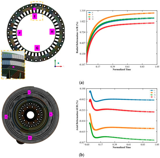
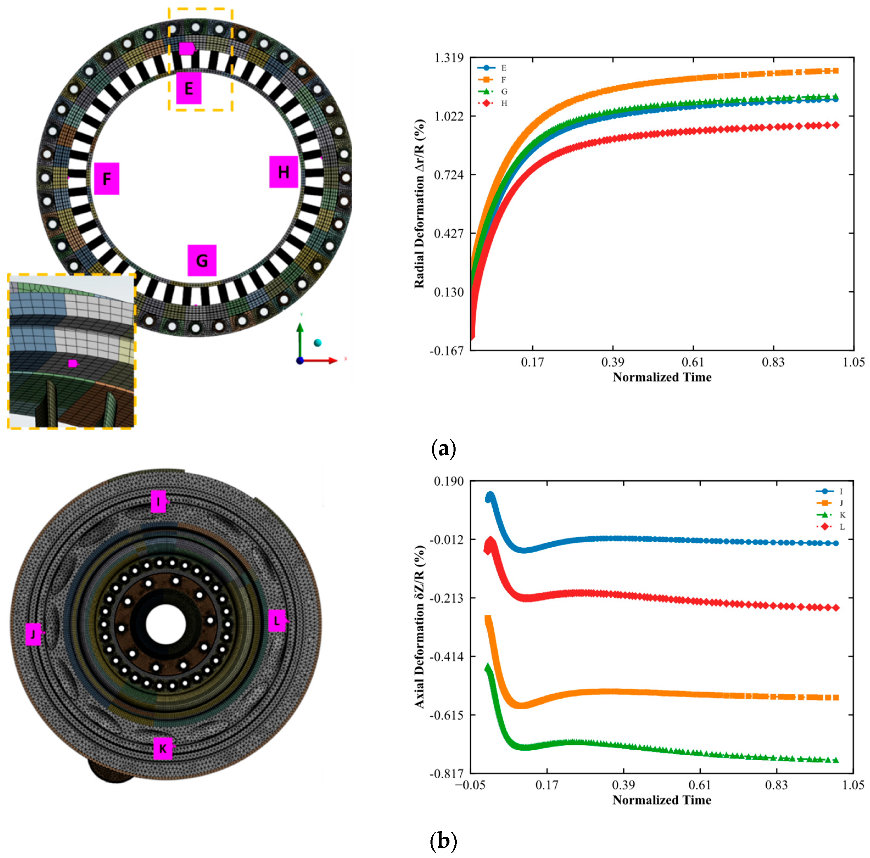
Furthermore, the axial deformation profiles for the same nodal set—represented in Figure 9—reveal complex transient shifting. The axial displacement exhibits initial fluctuations before following a more gradual trend, reflecting the non-uniform heating of the stator flanges and nozzle regions. The fact that the stator remains in a transient state while the rotor approaches stability suggests that the operational clearance between the blisk and the casing is highly dynamic. This divergence in thermal response times between the rotating and stationary assemblies poses a critical challenge for clearance management, as the minimum gap—and thus the highest risk of mechanical interference—may occur well after the initial ignition sequence.
Figure 9.
Transient deformation histories of the turbine casing: (a) radial deformation, (b) axial deformation.
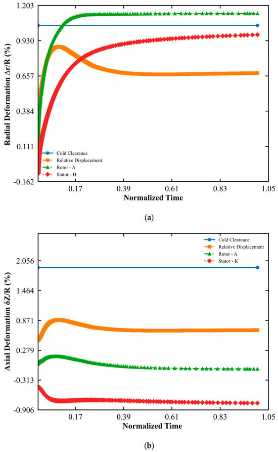
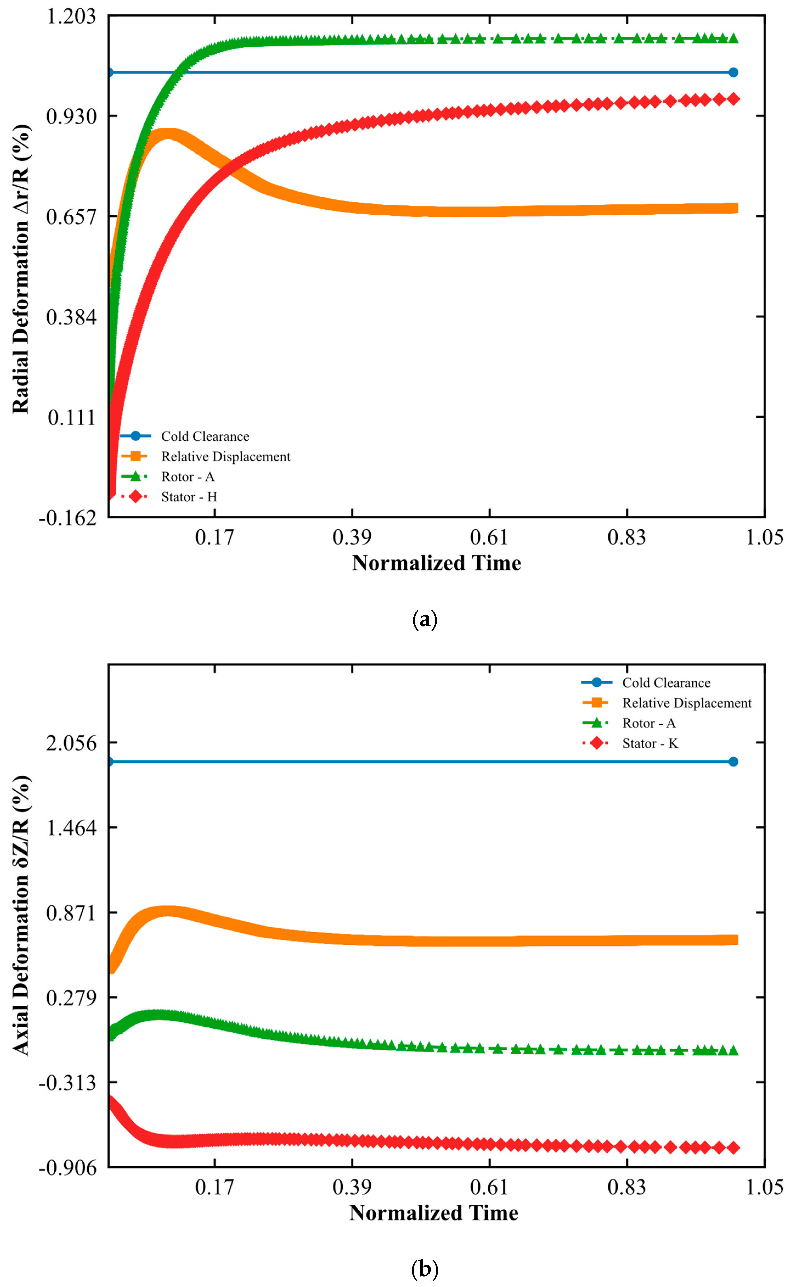
The operational safety of the turbopump assembly is primarily determined by the dynamic clearance between the rotating and stationary components. To evaluate the risk of mechanical interference, a superposition method was employed based on the transient radial and axial deformations calculated for both the turbine blisk and the stator housing, and results are given in Figure 10a,b for radial and axial directions, respectively.
Figure 10.
Dynamic clearance assessment of the turbopump assembly during the transient start-up sequence: (a) radial clearance, (b) axial clearance.
The radial clearance assessment, presented in Figure 10a, focuses on the most critical interaction point where the maximum radial expansion of the blisk meets the minimum radial growth of the stator. In this analysis, the peak radial displacement was observed at node location A of the blisk blade tip, while the minimum stator expansion occurred at node location H. The net operational clearance was determined by subtracting these displacement histories from the initial cold radial clearance of approximately of the radius of turbine disk.
The results indicate a significant transient reduction in clearance during the initial of operation, driven by the rapid thermal expansion of the rotor while the stator remains relatively cool due to its higher thermal inertia. However, even at the point of maximum relative displacement, a positive gap is maintained. Throughout the entire operational period, the analysis predicts no radial rotor–stator contact, ensuring the structural and aerodynamic integrity of the turbine stage.
Furthermore, the overall transient clearance trajectory shown in Figure 10a—characterized by an initial cold clearance of 1.05% R, a sharp transient ‘pinch point’ (maximum relative closure of 0.88% R, leaving a minimum safe running gap of 0.17% R) occurring at 12.9% of the operational period, followed by gradual clearance recovery as the high-thermal-inertia stator expands—is in complete qualitative and mechanistic agreement with transient turbine tip clearance profiles established in the literature [18,26,37]. Specifically, Lattime and Steinetz [18] and Kumar et al. [26] demonstrated that uncooled gas and rocket turbine stages invariably experience their minimum radial tip clearance shortly after start-up acceleration due to the faster thermal time constant of the rotor blades relative to the thick outer casing, before recovering to a wider steady-state running gap.
5. Conclusions
This study presents a high-fidelity, sequentially coupled multiphysics framework to evaluate the transient thermomechanical behavior of a satellite launch vehicle turbopump during the lift-off sequence. The integrated methodology successfully captured the complex interactions between fluid dynamics, heat transfer, and structural response under extreme operational conditions by utilizing a transient thermal finite element analysis. By mapping CHT-derived boundary conditions onto a solid mesh, the time-dependent internal temperature gradients and thermal lag throughout the system’s geometry were accurately resolved. This approach provided a robust foundation for identifying critical stress states and deformations that occur during the initial stages of the ascent trajectory.
The thermal analysis results revealed a significant divergence in the response times between the rotary and stationary assemblies, driven by the varying mass and material properties of the components. While the turbine blisk approached a steady-state condition within a relatively short interval, the stator housing exhibited persistent transient behavior throughout the observation interval of the operational period due to its substantial thermal inertia. Peak temperatures identified in the turbine and nozzle regions created severe localized thermal gradients, which served as the primary drivers for the subsequent structural deformation profiles. These transient temperature fields continuously influenced the energy balance of the system, underscoring the necessity of a time-dependent analysis for accurate reliability predictions.
Structural evaluations further confirmed that the radial growth at the turbine blade tip is primarily dominated by thermal expansion rather than mechanical loads. The analysis also captured a distinct dual-phase axial bending behavior in the turbine blisk, where the component initially shifted toward the nozzle side due to rapid surface heating before gradually moving toward the exhaust side as thermal equilibrium evolved. Ultimately, the dynamic clearance assessment confirmed that both radial and axial gaps remained positive throughout the transient regime. By using a superposition method to evaluate the relative displacement between the rotor and stator, the study demonstrates that the initial cold clearances were sufficient to prevent mechanical interference under peak operational loads.
Future research will aim to build upon these findings by incorporating experimental validation to further refine the predictive accuracy of the transient thermomechanical model. Additionally, the current framework will be expanded to include low-cycle fatigue and creep analysis to evaluate the long-term structural durability of the turbopump assembly under repeated operational cycles. Subsequent investigations may also focus on the optimization of material pairings and structural geometries to further minimize the sensitivity of blade tip clearances to extreme thermal gradients. Finally, extending the simulation to encompass the entire ascent trajectory beyond the initial startup phase will provide a more comprehensive understanding of the system’s performance and structural reliability across diverse flight conditions.
Author Contributions
Conceptualization, M.E.P. and Y.E.O.; methodology, M.E.P., Y.E.O., M.F.G., I.K. and S.C.; software, M.E.P., Y.E.O. and M.F.G.; validation, M.E.P., Y.E.O. and M.F.G.; formal analysis, M.E.P., Y.E.O., M.F.G., I.K. and S.C.; investigation, M.E.P. and Y.E.O.; resources, M.E.P., Y.E.O., M.F.G. and I.K.; data curation, M.E.P., Y.E.O. and M.F.G.; writing—original draft preparation, M.E.P., Y.E.O. and M.F.G.; writing—review and editing, I.K. and S.C.; visualization, M.E.P., Y.E.O. and M.F.G.; supervision, I.K. and S.C.; project administration, I.K.; funding acquisition, I.K. All authors have read and agreed to the published version of the manuscript.
Funding
This research received no external funding.
Data Availability Statement
The datasets presented in this article are not readily available because the data are confidential. Requests to access the datasets should be directed to Roketsan Incorporation.
Conflicts of Interest
Authors Muhammed Emin Polat, Yunus Emre Ozcelik, Mehmet Furkan Gorgulu and Iskender Kayabasi were employed by the company Roketsan Incorporation. The remaining authors declare that the research was conducted in the absence of any commercial or financial relationships that could be construed as a potential conflict of interest.
References
- Sutton, G.P.; Biblarz, O. Rocket Propulsion Elements, 9th ed.; John Wiley & Sons: Hoboken, NJ, USA, 2016. [Google Scholar]
- Huzel, D.K.; Huang, D.H. Modern Engineering for Design of Liquid-Propellant Rocket Engines; AIAA: Washington, DC, USA, 1992; Volume 147. [Google Scholar]
- Nosaka, M.; Oike, M.; Kikuchi, M.; Kamijo, K.; Tajiri, M. Ultra-high-speed performance of ball bearings and annular seals in liquid hydrogen at up to 3 million DN (120,000 rpm). Tribol. Trans. 2004, 47, 522–529. [Google Scholar] [CrossRef] [Scilit]
- Wang, T.; Ding, L.; Yu, H. Research and Development of Fault Diagnosis Methods for Liquid Rocket Engines. Aerospace 2022, 9, 481. [Google Scholar] [CrossRef] [Scilit]
- Jeon, S.-M.; Kwak, H.D.; Yoon, S.H.; Kim, J. Turbopump Rotordynamic Analysis for a 75 Ton Class Liquid Rocket Engine. In Proceedings of the 60th International Astronautical Congress (IAC 2009), Daejeon, Republic of Korea, 12–16 October 2009; Volume 7, pp. 5324–5329. [Google Scholar]
- Rubin, S. Longitudinal instability of liquid rockets due to propulsion system-structure interaction. J. Spacecr. Rockets 1966, 3, 1431–1437. [Google Scholar] [CrossRef] [Scilit]
- Veres, J.P. Centrifugal and Axial Pump Design and Off-Design Performance Prediction; NASA TM-106745; NASA Lewis Research Center: Cleveland, OH, USA, 1994.
- Sobin, A.J.; Bissell, W.R. Turbopump Systems for Liquid Rocket Engines; NASA SP-8107; National Aeronautics and Space Administration: Washington, DC, USA, 1975.
- Japikse, D.; Baines, N.C. Introduction to Turbomachinery; Concepts ETI, Inc.: White River Junction, VT, USA, 1997. [Google Scholar]
- Abdul-Aziz, A. Structural Evaluation of a Space Shuttle Main Engine (SSME) High Pressure Fuel Turbopump Turbine Blade; NASA Contractor Report 198497; NASA Lewis Research Center: Cleveland, OH, USA, 1996.
- Duplaa, S.; Coutier-Delgosha, O.; Dazin, A.; Roussette, O.; Bois, G.; Caignaert, G. Experimental Study of a Cavitating Centrifugal Pump During Fast Startups. ASME J. Fluids Eng. 2010, 132, 021301. [Google Scholar] [CrossRef] [Scilit]
- Tsukamoto, H.; Ohashi, H. Transient Characteristics of a Centrifugal Pump During Starting Period. J. Fluids Eng. 1982, 104, 6–13. [Google Scholar] [CrossRef] [Scilit]
- Abdul-Aziz, A.; Thompson, R.L. Thermal-structural analyses of Space Shuttle Main Engine (SSME) hot section components. In Proceedings of the Lewis Structures Technology Volume 2: Structural Mechanics, Cleveland, OH, USA, 24–25 May 1988. [Google Scholar]
- Joseph, J.; Agrawal, G.; Agarwal, D.; Pisharady, J.C.; Kumar, S.S. Chilldown study of cryogenic turbopump bearing coolant cavity. In Proceedings of the International Conference on Aerospace and Mechanical Engineering (ICAME’15), Kollam, Kerala, India, 14–16 December 2015. [Google Scholar]
- Saraf, A.M.; Traudt, T.; Oschwald, M. LUMEN Turbopump: Preliminary Thermal Model. J. Phys. Conf. Ser. 2021, 1909, 012052. [Google Scholar] [CrossRef] [Scilit]
- Roman, J. Thermal Analysis of the MC1 Engine Turbopump. In Proceedings of the Thermal and Fluids Analysis Workshop (TFAWS 2001), Huntsville, AL, USA, 10–14 September 2001. [Google Scholar]
- Kofskey, M.G.; Rohlik, H.E. Performance Evaluation of Three-Stage Prototype NERVA Turbine Designed for Blade-Jet Speed Ratio of 0.107; NASA TM X-719; National Aeronautics and Space Administration (NASA): Washington, DC, USA, 1963.
- Lattime, S.B.; Steinetz, B.M. Turbine Engine Clearance Control Systems: Current Practices and Future Directions; NASA Technical Memorandum, 2002-211794; NASA Glenn Research Center: Cleveland, OH, USA, 2002.
- Boyce, M.P. Gas Turbine Engineering Handbook, 4th ed.; Elsevier: Oxford, UK, 2011. [Google Scholar]
- Dorney, D.J.; Griffin, L.W.; Huber, F.W. A Study of the Effects of Tip Clearance in a Supersonic Turbine. J. Turbomach. 2000, 122, 674–683. [Google Scholar] [CrossRef] [Scilit]
- Childs, D.W. Transient Rotordynamic Analysis for the Space Shuttle Main Engine High-Pressure Oxygen Turbopump; NASA-CR-140455; National Aeronautics and Space Administration: Washington, DC, USA, 1974.
- Choi, Y.; Noah, S.T. Nonlinear Steady-State Response of a Rotor-Support System. J. Vib. Acoust. Stress Reliab. 1987, 109, 255–261. [Google Scholar] [CrossRef] [Scilit]
- Childs, D.W. Turbomachinery Rotordynamics: Phenomena, Modeling, and Analysis; John Wiley & Sons: New York, NY, USA, 1993. [Google Scholar]
- Muszynska, A. Rotor-to-stationary element rub-related vibration phenomena in rotating machinery. Shock Vib. Dig. 1989, 21, 3–11. [Google Scholar] [CrossRef] [Scilit]
- Ehrich, F.F. Handbook of Rotordynamics; McGraw-Hill: New York, NY, USA, 1992. [Google Scholar]
- Kumar, R.; Kumar, V.S.; Butt, M.M.; Sheikh, N.A.; Khan, S.A.; Afzal, A. Thermo-mechanical analysis and estimation of turbine blade tip clearance of a small gas turbine engine under transient operating conditions. Appl. Therm. Eng. 2020, 179, 115700. [Google Scholar] [CrossRef] [Scilit]
- Cowles, B.A. High cycle fatigue in aircraft gas turbines—An industry perspective. Int. J. Fract. 1996, 80, 147–163. [Google Scholar] [CrossRef] [Scilit]
- d’Agostino, L.; Brennen, C.E. Linearized dynamics of two-dimensional bubbly and cavitating flows over slender surfaces. J. Fluid Mech. 1989, 199, 155–176. [Google Scholar] [CrossRef] [Scilit]
- Brennen, C.E.; Acosta, A.J. Theoretical, quasi-static analysis of cavitation compliance in turbopumps. J. Fluids Eng. 1976, 98, 182–191. [Google Scholar]
- Lakshminarayana, B. Fluid Dynamics and Heat Transfer of Turbomachinery; John Wiley & Sons: New York, NY, USA, 1996. [Google Scholar]
- He, L. Fourier methods for turbomachinery applications. Prog. Aerosp. Sci. 2010, 46, 329–341. [Google Scholar] [CrossRef] [Scilit]
- Nielson, C.E.; Campany, A.D. Advanced Superposition Methods for High Speed Turbopump Vibration Analysis; NASA Contractor Report 165559; National Aeronautics and Space Administration: Washington, DC, USA, 1982.
- Moroz, L.; Frolov, B.; Kochurov, R. Steam Turbine Rotor Transient Thermo-Structural Analysis and Lifetime Prediction. In Proceedings of the ASME Turbo Expo 2016: Turbomachinery Technical Conference and Exposition, Volume 8: Microturbines, Turbochargers and Small Turbomachines, Steam Turbines, Seoul, Republic of Korea, 13–17 June 2016. [Google Scholar]
- He, S.; Tong, Z.; Tong, S.; Chen, K. Lifetime prediction of cryogenic hydrogen turbo-expander impellers via multi-fidelity thermal-fluid-solid interaction. Int. J. Hydrogen Energy 2025, 166, 150835. [Google Scholar] [CrossRef] [Scilit]
- Monteath, E.B.; Wagner, W.R.; Wong, G.S. Thermodynamic Improvements in Liquid Hydrogen Turbopumps; NASA Contractor Report (CR-102722); Rocketdyne: Canoga Park, CA, USA, 1969. [Google Scholar]
- Jeon, S.M.; Kwak, H.D.; Yoon, S.H.; Kim, J. Rotordynamic Analysis of a Turbopump with the Casing Structural Flexibility. J. Propuls. Power 2008, 24, 433–436. [Google Scholar] [CrossRef] [Scilit]
- Yoo, J.; Choi, J.-H.; Lee, I.; Han, J.-H.; Jeon, S.-M.; Kim, J.-H. Transient Heat Transfer and Structural Analyses for the Turbopump Turbine of a Liquid Rocket Engine. J. Korean Soc. Aeronaut. Space Sci. 2004, 32, 58–65. [Google Scholar] [CrossRef] [Scilit]
- Hoffman, J.; Jansson, J.; Stöckli, M. Unified continuum modeling of fluid-structure interaction. Math. Models Methods Appl. Sci. 2011, 21, 491–513. [Google Scholar] [CrossRef] [Scilit]
- Gafurov, S. Theoretical and Experimental Analysis of Dynamic Loading of a Two-Stage Aircraft Engine Fuel Pump and Methods for Its Decreasing. Ph.D. Thesis, Lappeenranta University of Technology, Lappeenranta, Finland, 2014. [Google Scholar]
- Kiris, C.C.; Kwak, D.; Chan, W.; Housman, J.A. Unsteady Flow Simulation of High Speed Turbopumps. In Computational Fluid Dynamics 2006; Deconinck, H., Dick, E., Eds.; Springer: Berlin/Heidelberg, Germany, 2009. [Google Scholar]
- Hong, S.-S.; Kim, D.-J.; Kim, J.-S.; Kim, J. System performance tests and start transient analysis of a liquid rocket engine turbopump. Proc. Inst. Mech. Eng. Part C J. Mech. Eng. Sci. 2012, 227, 470–480. [Google Scholar] [CrossRef] [Scilit]
- Gulczyński, M.T.; Riccius, J.R.; Zametaev, E.B.; Hahn, R.H.; Waxenegger-Wilfing, G.; Deeken, J.C.; Oschwald, M. Turbine Blades for Reusable Liquid Rocket Engines (LRE)—Numerical Fatigue Life Investigation. In Proceedings of the 2023 IEEE Aerospace Conference, Big Sky, MT, USA, 4–11 March 2023; pp. 1–11. [Google Scholar] [CrossRef] [Scilit]
- Abdul-Aziz, A.; Kalluri, S.; McGaw, M.A. Thermal and Structural Analysis of a Hollow Core Space Shuttle Main Engine (SSME) Turbine Blade; NASA Technical Memorandum 107089; National Aeronautics and Space Administration: Cleveland, OH, USA, 1995.
- Davidson, M.; Stephens, J. Advanced Health Management System for the Space Shuttle Main Engine. In Proceedings of the 40th AIAA/ASME/SAE/ASEE Joint Propulsion Conference and Exhibit, Fort Lauderdale, FL, USA, 11–14 July 2004; American Institute of Aeronautics and Astronautics: Reston, VA, USA, 2004. [Google Scholar][Green Version]

Disclaimer/Publisher’s Note: The statements, opinions and data contained in all publications are solely those of the individual author(s) and contributor(s) and not of MDPI and/or the editor(s). MDPI and/or the editor(s) disclaim responsibility for any injury to people or property resulting from any ideas, methods, instructions or products referred to in the content. |
© 2026 by the authors. Licensee MDPI, Basel, Switzerland. This article is an open access article distributed under the terms and conditions of the Creative Commons Attribution (CC BY) license.