


Abstract
A void between the concrete lining and surrounding rock interrupts the continuous support of lined rock caverns (LRCs) for compressed air energy storage (CAES). However, the load redistribution within the multilayer structure and the associated local response mechanisms remain unclear. This study focuses on a tunnel-type LRC with a steel liner as the sealing layer and develops a two-dimensional semi-analytical model considering local noncontact between the lining and surrounding rock. The model solves the segmented interface problem through substructural condensation, modal stiffness of the infinite surrounding rock, and Fourier point matching, and the results are numerically verified against two-dimensional finite element simulations. The results show that void behind lining induces spanning deformation of the lining and transfers the interface load to the intact contact zones on both sides. With increasing debonding extent, the spanning deformation, contact pressure near the boundaries, and circumferential stress of the steel liner continuously increase. The maximum spanning deformation occurs at the center of the debonding region, whereas the maximum tensile stress in the steel liner is located outside the debonding boundary, indicating that the local high stress is mainly related to load redistribution near the boundary. Under non-uniform in situ stresses, the structural response is jointly controlled by the initial cavern response and the local disturbance caused by debonding, and the unfavorable locations corresponding to deformation and steel liner stress are not identical. Parametric analysis further shows that concrete lining thickness and surrounding rock stiffness mainly reduce the debonding response by increasing the spanning stiffness and external support, while steel liner thickness mainly affects the stress level of the liner itself. The proposed method establishes a connection between local support loss, interface load redistribution, and sealing structure response, providing a theoretical basis for the mechanical analysis and defect evaluation of void behind lining in high-pressure LRCs.
1. Introduction
With the increasing proportion of renewable energy sources, such as wind and solar power, in power systems, their variability and intermittency have imposed higher requirements on large-scale and long-duration energy storage. Owing to its large storage capacity, long service life, and suitability for long-duration storage, CAES is an important physical energy storage option for accommodating high shares of renewable energy [1,2]. Large-scale CAES generally relies on underground spaces for storing high-pressure air, with existing storage options including salt caverns, abandoned mines, and artificial underground caverns. Salt caverns provide favorable natural sealing conditions; however, their application is restricted by the distribution of salt resources and geological conditions. LRCs can be constructed in a wider range of rock formations and therefore offer better site adaptability, making them an important direction for underground high-pressure gas storage in recent years [3,4].
An LRC generally consists of a sealing layer, concrete lining, and surrounding rock. These structural layers perform different functions and form a combined load-bearing system through deformation compatibility. The sealing layer mainly ensures the gas tightness of the storage space, the concrete lining provides continuous support for the sealing layer and transfers loads outward, while the surrounding rock serves as the main load-bearing medium to resist the internal pressure [3,5,6,7]. Therefore, the safe operation of LRCs relies on stable and effective load transfer among the multiple structural layers.
Extensive studies have been conducted on this multilayer storage system. Early investigations mainly focused on the gas tightness, surrounding rock response, and thermo-mechanical coupling behavior of shallow buried LRCs, establishing the basic framework for analyzing underground high-pressure storage structures [3,5,6,8,9,10]. Schmidt et al. [11] investigated the technical feasibility of using lined mining tunnels in closed coal mines as underground CAES reservoirs and evaluated their geomechanical performance and coupled thermo-mechanical response during cyclic operation. With increasing storage pressure and engineering scale of CAES facilities, research has gradually expanded to issues including overall stability, surrounding rock failure, safe burial depth, lining cracking, and structural optimization under high internal pressure. Jiang et al. [12] investigated the structural response of shallow buried LRCs through model tests and numerical simulations. Damasceno et al. [13] studied the mechanical response of surrounding rock subjected to high internal pressure. Xu et al. [14] developed an analytical solution for the elastoplastic response of lined rock caverns under initial hydrostatic stress and high internal pressure, accounting for the stress paths during excavation and operation. Xia et al. [15] simulated crack initiation and propagation in the lining using a thermo-mechanical coupled phase field method. Huang et al. [16] and Xu et al. [17] explored structural optimization approaches from the perspectives of prestressed lining and segmented lining, respectively. Geng et al. [18] further investigated the temperature and pressure responses during initial pressurization and cyclic operation. Jiang et al. [19] and Sun et al. [4] systematically summarized the key scientific issues and analytical methods related to LRCs in recent years, showing that a research framework centered on the surrounding rock, lining, sealing structure, and their interactions has gradually been established.
In recent years, the collaborative load-bearing behavior among different structural layers of LRCs and their mechanical responses during operation have received increasing attention. Xiang et al. [7] developed an analytical model for the multilayer structure and quantitatively evaluated the load sharing among the sealing layer, concrete lining, and surrounding rock under internal pressure, further demonstrating the important role of surrounding rock stiffness in the overall response. Wang et al. [20] simulated the propagation of lining cracks and their effects on the sealing structure response using the finite discrete element method. Jin et al. [21] further considered cavern layout and long-term stability under non-uniform in situ stresses and cyclic internal pressure conditions.
However, most existing studies on LRCs assume that the structural layers maintain complete contact and continuous support, which may not always be satisfied in practical underground engineering. Factors such as over-excavation, insufficient concrete compaction, inadequate backfilling, local surrounding rock spalling, and long-term operation may result in local debonding between the concrete lining and surrounding rock, interrupting the originally continuous interface support. For LRCs, this defect not only changes the stress state of the lining itself but may also interrupt the original load transfer path in local regions, causing internal pressure loads to redistribute toward the surrounding intact contact areas and further affecting the mechanical response of the inner sealing layer. Therefore, void behind lining does not simply represent a reduction in surrounding rock support; instead, it alters the original load transfer relationship among the multilayer structure. The multilayer structural theory proposed by Xiang et al. [7] also indicates that surrounding rock support plays an important role in load sharing within LRCs, suggesting that the effects of changes in local support conditions require further investigation.
Void behind linings has been studied extensively in conventional underground engineering. Meguid and Dang [22] investigated the influence of erosion cavities on existing tunnel linings and showed that local loss of support can significantly alter lining internal forces. Wang et al. [23] systematically examined the effects of void size, location, lateral pressure coefficient, surrounding rock conditions, and tunnel geometry on lining deformation and stress redistribution. Yasuda et al. [24] represented voids as local noncontact boundaries between the lining and surrounding rock and obtained a two-dimensional elastic solution for deep circular tunnels under far-field loading using the substructure method and point matching method. Their results theoretically demonstrated that void behind lining can change the lining response from being dominated by axial force to a more pronounced bending response. Subsequently, Zhao et al. [25] and Ye and Zhang [26] further discussed the influence of poor contact conditions on the structural safety of operating tunnels, while He et al. [27] revealed through model tests that crown void may change the lining failure mode from compression-controlled failure to bending tensile failure.
In recent years, studies on tunnel debonding have further extended from single internal force analysis to crack development, contact effects, repair methods, and three-dimensional interactions among multiple cavities. Zhang et al. [28] investigated tunnel structural performance considering the combined effects of debonding and existing cracks. Qiao et al. [29] analyzed crown debonding and grouting repair while considering the contact effect of waterproof layers. Ye et al. [30] studied the three-dimensional interaction among multiple cavities and found that cavity spacing can significantly affect local contact pressure and internal force distribution. Liu et al. [31] combined model tests and numerical simulations to analyze lining failure and stability evolution under different cavity locations and sizes. These studies have demonstrated that the key mechanical effect of debonding originates from changes in support conditions and the resulting redistribution of internal forces and contact pressure, while its influence is closely related to the debonding size, location, and in situ stress conditions.
Although the studies of void in conventional tunnels provide important references, their mechanical conditions differ significantly from those of CAES-LRCs. Conventional transportation tunnels mainly experience external loads from surrounding rock, and existing studies generally focus on changes in lining axial force, bending moment, cracking, and bearing capacity caused by debonding. In contrast, LRCs are subjected not only to far-field in situ stresses but also to high internal air pressure, with loads transferred successively through the sealing layer, concrete lining, and surrounding rock. After void behind lining occurs, the deformation of the spanning region, adjustment of interface loads near the debonding boundary, and local response of the inner sealing layer become coupled, making the problem different from cavities behind conventional linings under external ground loads. Moreover, in situ stresses are generally non-uniform, and the deformation and stress states around the cavern exhibit directional characteristics. The disturbance caused by void behind lining is therefore superimposed on this non-uniform initial stress and displacement state. Consequently, the debonding size and location effects obtained from conventional tunnels cannot be directly applied to explain the local responses of multilayer LRCs under high internal pressure, and existing LRC theories assuming complete contact are also insufficient for describing load redistribution after local loss of interface support.
Based on these considerations, this study investigates elastic load redistribution and structural response caused by prescribed local support loss at the concrete lining–rock interface. The objective is to clarify the associated load-transfer mechanism and the influence of defect geometry, in situ stress and structural stiffness, rather than to reproduce the complete mechanical response of an actual rock mass. Considering that steel plates provide good gas tightness and mature welding techniques, they are currently an important form of sealing layer in LRCs, while flexible materials such as rubber remain under continuous investigation and development [4,32]. Therefore, a typical LRC with a steel liner as the sealing layer is selected as the research object. For the circular multilayer system consisting of steel liner, concrete lining, and surrounding rock, a two-dimensional semi-analytical model considering local noncontact between the lining and surrounding rock is developed. The finite structural components composed of the steel liner and concrete lining and the infinite surrounding rock are represented separately, and the segmented interface conditions between intact contact zones and debonded zones are satisfied through Fourier expansion and point matching. After numerical verification against two-dimensional finite element results, the model is used to analyze spanning deformation, interface load redistribution, and steel liner response under void-behind-lining conditions. The effects of non-uniform in situ stresses and variations in operational, structural, and surrounding rock conditions on these responses are further investigated.
2. Theoretical Model and Solution Method
2.1. Problem Definition
A tunnel-type CAES underground storage cavern composed of a steel liner, concrete lining, and surrounding rock is considered, as shown in Figure 1. The inner surface of the steel liner is subjected to uniform internal air pressure , while the far-field vertical stress and horizontal stress are assumed to be and , respectively, where is the lateral pressure coefficient. The midsurface radius and thickness of the steel liner are denoted as and , respectively, while the inner and outer radius of the concrete lining are represented by and , respectively.
Figure 1.
Mechanical model of a CAES-LRC with void behind the lining.
The steel liner, concrete lining and surrounding rock are assumed to be homogeneous, isotropic and linearly elastic, with Young’s moduli and Poisson’s ratios denoted by , and , respectively. The steel liner is represented using thin-shell theory, and the concrete lining is described by a plane-strain thick-ring formulation. The concrete lining is assumed to remain uncracked and retain its assigned elastic stiffness throughout the analysis. The surrounding rock is idealised as an infinite elastic continuum, neglecting the influence of the ground surface, nearby openings and other finite boundaries. The void geometry and loading are assumed to be invariant along the cavern axis, allowing a plane-strain representation without axial end effects. The analysis considers prescribed mechanical loading without solving the temperature field or including thermal strains.
A void behind lining zone exists between the concrete lining and surrounding rock and is represented as a local noncontact boundary. The direction of the vertical principal stress is taken as , the center position of the debonding zone is , the half angular extent of the debonding zone is , and the total angular extent is . The debonded region and intact contact region are defined as:
where denotes the entire lining–rock interface.
Within , the lining and surrounding rock satisfy displacement compatibility and interface force equilibrium. Within , both surfaces are traction-free, and no radial or tangential stresses are transferred across the interface. This binary interface condition represents the limiting case of complete local loss of support rather than all possible forms of construction-induced defects. The radial displacement is considered positive outward, the tangential displacement is considered positive in the increasing direction of , and tensile stress is defined as positive.
2.2. Solution Framework
Void behind lining transforms the originally continuous lining–rock interface into a mixed boundary that varies segmentally along the cavern perimeter. To address this interface nonuniformity, the overall system is divided into a steel liner–concrete lining substructure and a surrounding rock substructure, as illustrated in Figure 2. The former carries the internal pressure and transfers the load to the outer surface of the concrete lining, while the latter describes the far-field in situ stress and the additional response of the infinite surrounding rock induced by interface reactions.
Figure 2.
Substructure decomposition: (a) steel liner–concrete lining substructure; (b) surrounding rock substructure.
Established analytical solutions are available for circular thin shells, plane strain thick-walled rings, and infinite elastic surrounding rock [6,7,24]. Their complete derivations are therefore not repeated here. Instead, the emphasis is placed on how these basic solutions are coupled under void-behind-lining conditions. For each harmonic order , the internal degrees of freedom of the steel liner–concrete lining system are first eliminated through static condensation. The composite lining is then represented by an equivalent modal stiffness and an equivalent internal pressure load at the outer surface of the concrete lining. The surrounding rock response is decomposed into a far-field fundamental solution and an additional field induced by interface actions.
Displacement compatibility and force equilibrium are imposed in the intact contact region, whereas traction-free boundary conditions are applied to both sides of the interface in the debonded region. The interface displacements and tractions are then expanded into truncated Fourier series and solved using point matching. This formulation follows the framework developed by Yasuda et al. [24] for circular tunnels with local noncontact boundaries, while further incorporating a steel liner–concrete composite lining subjected to internal air pressure and simultaneously accounting for non-uniform in situ stresses and arbitrary debonding locations.
2.3. Modal Boundary Relations of the Substructure
2.3.1. Steel Liner-Concrete Lining Substructure
Both the steel liner and concrete lining are concentric circular elastic structures, and the Fourier modes of different orders are mutually independent. Taking the type A harmonic as an example, the radial component is expressed in terms of , while the tangential component is expressed in terms of . According to thin cylindrical shell theory, the interface force and displacement coefficients of the th order mode of the steel liner satisfy
where the circumferential extensional stiffness and bending stiffness of the steel liner are, respectively,
The modal stiffness matrix of the steel liner in Equation (2) can be obtained directly from the standard thin shell equations. Uniform internal pressure contributes directly only to the axisymmetric component with . Therefore, the element-by-element expression of the stiffness matrix is not repeated here.
The concrete lining is described using the plane strain thick ring solution. The Airy stress function, general stress–displacement solution, and treatment of the special low-order modes can be found in Zhou et al. [6] and Yasuda et al. [24]. Let denote the generalized coefficient vector of the th order thick ring solution. The displacements and forces at the inner and outer boundaries can then be written in matrix form as
After eliminating the generalized coefficient vector, a direct stiffness relation between the inner and outer boundaries of the concrete ring is obtained:
The steel liner and concrete lining are perfectly bonded. Therefore, displacement compatibility and force equilibrium are satisfied at their common interface:
Substituting Equations (2) and (5) into Equation (6) gives the equilibrium equation for the common displacement at the inner boundary:
Accordingly, the common displacement of the steel liner and the inner surface of the concrete lining can be expressed as
The interface force at the outer surface of the concrete lining can then be written as
where the equivalent outer boundary stiffness of the composite lining and the equivalent transmitted load induced by the internal pressure are, respectively,
Let . The steel liner–concrete lining substructure can then be condensed into the following unified modal boundary relation:
The effect of internal air pressure is represented by an equivalent load acting on the outer boundary of the lining, while the internal degrees of freedom of the composite lining are condensed to this boundary. Once is obtained, the internal responses of the steel liner and concrete lining can be recovered from Equation (8) and the general solution for the thick ring.
2.3.2. Surrounding Rock Substructure
The response of the surrounding rock is decomposed into the basic field of an unlined circular opening subjected to far-field in situ stresses and the additional field induced by the interaction at the lining–rock interface:
At the cavern wall , the total displacement is obtained by superposing the basic and additional fields:
The far-field in situ stresses affect only the basic field associated with the traction-free cavern boundary and do not alter the modal stiffness of the additional field in the surrounding rock. Let , and define the characteristic displacement amplitude as
When , the far-field stress state is hydrostatic, and the free cavern boundary contains only an axisymmetric contraction component:
When , the far field can be decomposed into a mean stress component and a deviatoric stress component. The displacement of the free cavern boundary is
In the global coordinate system where the vertical principal stress direction is taken as , the corresponding basic field contains only the and type A modes:
Therefore, the basic field is rotationally invariant when . When , the second-order nonaxisymmetric component is fixed relative to the principal in situ stress direction, providing the underlying non-uniform state responsible for the debonding location effect.
The additional field in the surrounding rock is described using the infinite domain elastic solution for a circular opening. Let denote the coefficient vector of the th order additional field. The boundary displacement and interface force then satisfy
Eliminating the generalized coefficient vector gives the modal boundary stiffness of the surrounding rock:
Thus, the total force-displacement relation of the surrounding rock at the interface can be written as:
2.4. Interaction Solution Under Void Behind Lining
2.4.1. Piecewise Interface Conditions
Void behind lining is introduced directly into the solution through piecewise boundary conditions. Regardless of whether the far-field stress is hydrostatic, displacement compatibility and interface force equilibrium are satisfied within the intact contact region :
Within the debonded region , both the outer surface of the lining and the cavern wall of the surrounding rock are traction-free:
The displacements on the two sides of the debonded region are independent; therefore, no displacement compatibility condition is imposed.
2.4.2. Fourier Expansion
When , a local angular coordinate can be introduced such that the center of the debonded region is located at . Because the far-field basic solution is rotationally invariant, the problem is mirror symmetric about the center of the debonded region. Accordingly, only cosine terms are required for the radial components, whereas only sine terms are retained for the tangential components:
where the angular function matrix is
When and the debonding location does not coincide with a symmetry axis of the principal stresses, the debonding partition and the far-field basic solution no longer share the same axis of mirror symmetry. Therefore, two independent sets of harmonics, denoted as A and B, must be retained for each order over the full circumference. For either substructure :
Because all substructures are concentric circular systems, their modal stiffness relations are identical for each harmonic order, and the type B harmonics differ from the type A harmonics only in phase. Uniform internal pressure acts directly only on the component, whereas the non-uniform far-field basic solution contributes only to the and type A components. Void behind lining couples different modes through the piecewise boundary conditions over the full circumference.
2.4.3. Point Matching and Solution of the Equations
Equations (21) and (22) constitute mixed boundary conditions that vary piecewise along the circumference, for which a rigorous closed-form solution is difficult to obtain directly. The point matching method is therefore adopted. For symmetric problems, collocation points need only be distributed over half of the circumference. For general problems, the points are distributed over the full circumference according to the actual debonding location. The collocation points are placed away from the ends of the debonded region to reduce Gibbs oscillations caused by abrupt changes in the boundary conditions.
Substituting Equations (11) and (20), together with the corresponding Fourier expansions, into the boundary conditions of the intact contact and debonded regions yields a linear algebraic system:
The unknown vector consists of the independent Fourier coefficients of the displacements at the outer surface of the lining and the cavern wall of the surrounding rock. After truncation at order , Gauss–Legendre interior points are assigned in each of the two regions to construct an overdetermined system, which is solved by a least squares procedure using pivoted QR decomposition. The rigid body translation associated with the mode of the surrounding rock is eliminated following the constraint treatment of Yasuda et al. [24]. The displacement and force equations are normalized separately using their respective characteristic scales and are assigned integration weights to improve numerical stability at high-order truncation.
Because the interface condition changes abruptly from contact to traction-free at the ends of the debonded region, the interface force may exhibit a steep gradient near these locations, and its convergence is generally slower than that of displacement and structural stress. Therefore, the convergence with respect to the Fourier truncation order is first examined in Section 3. In the subsequent evaluation of interface loads, distributed values away from the end neighborhoods are used rather than the single-point extrema at the debonding ends.
2.5. Calculation of Structural Responses
After solving Equation (26), the Fourier displacement coefficients at the outer boundary of the lining and the surrounding rock cavern wall are obtained. The interface forces on both sides can then be calculated using Equations (11) and (20). The main response quantities used in the subsequent analyses are given below.
First, the common displacement of the steel liner and the inner surface of the concrete lining is recovered from Equation (8):
Let the radial and tangential components of the common displacement be and , respectively. The th-order circumferential force and bending moment of the steel liner are then given by
After superposing all harmonic orders, the circumferential distributions of the steel liner force and bending moment are
Accordingly, the circumferential stresses at the two surfaces of the steel liner are
Equation (30) includes the contributions of both the circumferential force and bending moment. In the following analysis, the circumferential stress of the steel liner refers to the controlling value from the two surfaces, so as to characterize the most unfavorable surface stress caused by void behind lining.
The internal response of the concrete lining is determined from the displacements at its inner and outer boundaries. The coefficient vector of the th order general solution is
Therefore, the displacement and stress at any position within the concrete lining can be expressed as:
The displacement and stress vectors are defined as
The coefficients of the additional field in the surrounding rock are determined from the additional displacement at the cavern wall:
The total displacement and stress at any position in the surrounding rock are obtained by superposing the far-field basic solution and the additional field:
Within the intact contact region, the normal contact pressure at the lining–rock interface is defined as positive in compression:
No normal pressure is transmitted within the debonded region; therefore,
To characterize the spanning deformation within the debonded region, the relative radial displacement between the lining and surrounding rock is defined as
Equation (37) gives the distribution of the support load within the intact contact region, while Equation (38) quantifies the spanning deformation in the debonding region. Together with the axial force, bending moment, and surface circumferential stress of the steel liner, as well as the displacement and stress fields within the concrete lining and surrounding rock, these quantities allow the transfer of internal air pressure from the steel liner to the concrete lining and surrounding rock to be traced within a unified framework. The effects of void behind lining on load redistribution and the responses of the individual structural layers can then be evaluated.
3. Numerical Verification
To verify the correctness and numerical accuracy of the proposed semi-analytical formulation, its results are compared with those obtained from separately implemented two-dimensional finite element models under symmetric and asymmetric debonding conditions. The finite element models intentionally adopt the same plane-strain, linear-elastic material assumptions and idealized interface conditions as the semi-analytical model, while employing a different spatial-discretization-based solution procedure. Therefore, the comparison provides cross-method numerical verification of the theoretical derivation, Fourier-series implementation, enforcement of the piecewise boundary conditions, and calculation of the structural responses. It should not be interpreted as experimental or physical validation of the shared constitutive and interface assumptions.
The air storage cavern has an inner diameter of 12.0 m, a concrete lining thickness of 0.50 m, and a steel liner thickness of 8 mm. The reference far-field in situ stress is MPa, the lateral pressure coefficient is , and the internal air pressure is MPa. The remaining parameters are listed in Table 1.
Table 1.
Mechanical parameters of structures.
Before comparison with the finite element results, the limiting behavior of the solution procedure was first examined. When , the lining–rock interface returns to complete continuous contact, and the point matching solution should reduce to the direct modal solution in which different harmonic orders are uncoupled. The calculated radial displacement at the interface for the mode is 1.7 mm, which agrees with the direct modal solution. The displacement Fourier coefficients for all modes are at the level of numerical zero. This confirms the consistency of the static condensation, the modal stiffness formulation of the surrounding rock, and the assembly of the global equations under complete contact conditions.
3.1. Numerical Convergence
The case with is selected to represent a relatively strong local disturbance. Gauss–Legendre interior points are distributed in the debonded and intact contact regions for point matching, while the Fourier truncation order is progressively increased. The total number of collocation points is denoted by . To quantify how well the piecewise boundary conditions are satisfied, the normalized root mean square residual is introduced, with a smaller value indicating better satisfaction of the prescribed interface conditions. To reduce the influence of Gibbs oscillations near the debonding ends, the neighborhoods on both sides are excluded from the evaluation of . The radial displacement of the lining at the debonding center is denoted by , while the circumferential stress at the governing surface of the steel liner at the same location is denoted by . Table 2 compares the convergence of these quantities for different values of .
Table 2.
Convergence with Fourier truncation order for = 60°.
As increases, the boundary-condition residual decreases continuously, whereas the steel-liner stress at the center of the debonded region converges more slowly than the lining displacement. Taking the result in Table 2 as the comparison reference, at , the relative differences in the lining displacement and steel-liner stress are 0.019% and approximately 1.37%, respectively, while the root mean square residual of the boundary conditions outside the end neighborhoods is approximately 0.13%. These results indicate that the convergence of the displacement and boundary-condition residual alone is insufficient to evaluate the sensitivity of the steel-liner stress to the Fourier truncation order. Therefore, an additional stress-specific convergence assessment is performed for the maximum circumferential stress at the governing steel-liner surface and its location.
The case in Table 2 is used as a numerical benchmark with a pronounced local disturbance, whereas the additional assessment considers representative symmetric and asymmetric cases within the parameter ranges investigated in the subsequent sections. The symmetric case is defined by , , and , while the asymmetric case is defined by , , and . The symmetric half-circumference formulation employs , whereas the asymmetric full-circumference formulation employs , thereby maintaining the same ratio of equations to unknowns. In Table 3, and denote the relative difference in the maximum steel-liner stress and the absolute change in the stress-peak location, respectively, with respect to the results. The results are used only as higher-order numerical references and are not regarded as exact solutions.
Table 3.
Stress sensitivity for representative cases.
For the symmetric and asymmetric cases, the differences in the maximum stress at are 3.274% and 4.172%, respectively, while the corresponding changes in the peak locations are only and . When is increased to 960, the stress differences decrease to 0.673% and 0.836%, respectively. As increases, the maximum stress gradually decreases, whereas the peak location remains nearly unchanged. Therefore, in both representative cases, provides a slightly higher estimate of the local stress peak without changing the identified stress-concentration location. The subsequent parametric analyses aim to identify the load-redistribution mechanism, stress-concentration location, and relative response trends induced by local support loss. Considering the limited sensitivity of the stress peak to the truncation order, the stability of the peak location, and the computational cost of the systematic parametric analyses, is adopted for the subsequent calculations.
3.2. Numerical Verification Against the Two-Dimensional Finite Element Model: Symmetric Debonding
The two-dimensional finite element model adopts the same plane strain conditions as the semi-analytical model. The steel liner is represented by a closed ring of B22 quadratic beam elements at the midsurface radius , with equivalent elastic properties assigned so that its extensional and bending stiffnesses are consistent with those of the theoretical thin ring model. The concrete lining and surrounding rock are discretized using quadrilateral elements. The steel liner is perfectly bonded to the concrete lining, while displacement compatibility is imposed at the lining–rock interface only within the intact contact region. No connection is established within the debonded region, consistent with the piecewise boundary conditions of the theoretical model. The two-dimensional finite element model is shown in Figure 3, with an overall domain size of . Horizontal displacement is constrained along the left boundary and vertical displacement along the bottom boundary, while far-field compressive stresses and are applied to the right and top boundaries, respectively. For the baseline case, , and the applied far-field stress on both boundaries is 3.75 MPa.
Figure 3.
Two-dimensional finite element model.
Four debonding cases with , , , and are selected for comparison. The Fourier truncation order determined from the preceding convergence analysis is used consistently in the semi-analytical solutions. The radial displacement of the surrounding rock cavern wall, the radial displacement of the inner surface of the lining, and the circumferential stress of the steel liner are compared. In Figure 4, Figure 5 and Figure 6, the solid lines represent the semi-analytical results, while the open symbols denote the finite element results. The shaded region and the dashed lines on both sides indicate the actual extent of the debonded region. Because the structural response is symmetric about the center of the debonded region when , only the results within around the debonded region are presented.
Figure 4.
Comparison of semi-analytical and finite element results for the radial displacement of the surrounding rock cavern wall within – under different debonding angles: (a) ; (b) ; (c) ; (d) .
Figure 5.
Comparison of semi-analytical and finite element results for the radial displacement of the inner surface of the lining within – under different debonding angles: (a) ; (b) ; (c) ; (d) .
Figure 6.
Comparison of semi-analytical and finite element results for the circumferential stress at the governing surface of the steel liner within – under different debonding angles: (a) ; (b) ; (c) ; (d) .
Figure 4 compares the semi-analytical and finite element results for the radial displacement of the surrounding rock cavern wall under different debonding extents. As increases, the radial displacement of the surrounding rock within the debonded region gradually decreases, while the local displacement gradient near the debonding ends becomes more pronounced. Away from the debonded region, the responses for the different cases gradually converge. For all four cases, the two methods show good agreement in both the overall distribution and the variations near the debonding ends, with relative errors below 3.89%. Once the surrounding rock within the debonded region is no longer subjected to direct interface interaction from the lining, its local response is reduced, while the load is redistributed toward the intact contact regions on both sides, resulting in more concentrated displacement variations near the debonding ends.
Figure 5 compares the radial displacement of the inner surface of the lining for different debonding extents. As increases, the lining exhibits more pronounced spanning deformation in the region where surrounding rock support is lost, and the maximum displacement consistently occurs near the center of the debonded region. After entering the intact contact region, the displacement decreases rapidly. The semi-analytical and finite element results show good agreement in the peak value, the width of the spanning region, and the attenuation behavior on both sides, with a maximum relative error of 6.14%. This response of the lining is directly related to the local support conditions. As the debonded region expands, the unsupported span of the lining increases, and the effective support position moves farther from the debonding center, further amplifying the radial deformation in the central region. In contrast, once the lining enters the intact contact region, radial deformation is rapidly restrained by the surrounding rock.
Figure 6 further compares the circumferential stress in the steel liner under different debonding extents. As increases, the local nonuniformity of the stress distribution becomes more pronounced. The stress near the center of the debonded region decreases, while increasingly distinct tensile stress peaks develop outside the boundaries on both sides. For , , , and , both the semi-analytical and finite element results indicate that the peak stress occurs outside the debonding boundary, with a maximum relative error of 3.85%. The difference in the locations of the maximum deformation and maximum stress indicates that the local steel liner stress is governed not only by the magnitude of the spanning deformation, but also by the redistribution of structural forces near the debonding ends.
Figure 4, Figure 5 and Figure 6 show that the semi-analytical model provides good predictions of the surrounding rock displacement, lining spanning deformation, and local steel liner stress. The differences between the two methods are mainly concentrated in the high gradient regions near the debonding ends, while the overall distribution patterns, response amplitudes, and key locations remain in good agreement. The numerically verified semi-analytical framework can therefore be used to further investigate the interface interaction and multilayer structural responses induced by variations in debonding extent.
3.3. Numerical Verification Against the Two-Dimensional Finite Element Model: Asymmetric Debonding
The preceding numerical verification mainly considers the symmetric case with . The general Fourier formulation developed in Section 2 is also intended to address cases with non-uniform far-field stresses and debonding locations that do not coincide with the principal stress axes. To verify this capability, an offset debonding case is further considered with a total debonding angle of and a debonding center at . Two lateral pressure coefficients, and 1.5, are examined, while all other geometric, material, and loading parameters remain unchanged. In these cases, the debonding location is inclined relative to the far-field principal stress directions, and the structural response is no longer symmetric about the centerline of the debonded region. Therefore, both type A and type B Fourier harmonics are retained in the semi-analytical solution.
Figure 7 presents the radial displacement of the surrounding rock cavern wall, the radial displacement of the inner surface of the lining, and the circumferential stress of the steel liner within . For both in situ stress states, the semi-analytical curves agree well with the discrete finite element results. Apart from small local differences near the debonding ends, the overall trends, local transitions, and the locations of the high steel liner stress regions are consistently reproduced. For and , the relative errors in the peak steel liner stress are 0.55% and , respectively, while the corresponding errors in the peak locations are and .
Figure 7.
Comparison of semi-analytical and finite element results for the non-uniform in situ stress and offset debonding cases within –: (a) radial displacement of the surrounding rock cavern wall; (b) radial displacement of the inner surface of the lining; (c) circumferential stress at the governing surface of the steel liner. The orange dashed lines and shaded region indicate the boundaries and extent of the debonded region, respectively. Solid lines represent the semi-analytical results, while open circles represent the finite element results.
Compared with the symmetric case, the most evident feature in Figure 7 is that the responses on the two sides of the debonded region are no longer identical. As changes, the pre-existing stress and displacement fields around the cavern also change, so that the local disturbance induced by debonding is superimposed on a different nonuniform state at each location. As a result, the steel liner stress peaks on the two sides of the debonded region differ in magnitude, and the asymmetric distributions for and are also different. The semi-analytical results reproduce these asymmetric responses and accurately predict both the magnitude and location of the peak steel liner stress, demonstrating that the general Fourier formulation can account for the combined effects of non-uniform in situ stresses and offset debonding.
Overall, the agreement obtained for both the symmetric and asymmetric cases confirms the numerical consistency of the semi-analytical and finite element solutions within the shared plane-strain, linear-elastic, and idealized-interface framework. The reported differences therefore quantify the numerical discrepancy between the two solution procedures, rather than the physical accuracy of the common modelling assumptions. On this basis, the semi-analytical model is subsequently used to investigate the mechanisms and parametric trends of elastic load redistribution caused by local loss of support.
4. Load Redistribution and Location Effects Induced by Void Behind Lining
4.1. Debonding Extent and Interface Load Redistribution
With MPa, , and MPa, four debonding extents of , , , and are considered. Figure 8 presents the relative radial displacement between the lining and surrounding rock, the interface contact pressure, and the circumferential stress at the governing surface of the steel liner near the debonded region. As shown in Figure 8a, the relative radial displacement within the debonded region increases markedly with increasing , and its maximum consistently occurs near the center of the debonded region. As increases from to , the maximum relative displacement increases from approximately 0.614 mm to 6.638 mm. The expansion of the debonded region increases the span over which the lining loses surrounding rock support, thereby amplifying the spanning deformation.
Figure 8.
Local structural responses under different debonding extents: (a) relative radial displacement between the lining and surrounding rock; (b) interface contact pressure (2° moving average); (c) circumferential stress at the governing surface of the steel liner. The orange dashed lines and shaded regions indicate the boundaries and extents of the debonded regions, respectively. Different colors and symbols correspond to the debonding extents labeled in each row.
In contrast to the displacement response, the high values of contact pressure and steel liner tensile stress in Figure 8b,c occur near the debonding boundaries rather than at the center of the debonded region. The interface contact pressure directly reflects where the load is transferred. Within the debonded region, the lining and surrounding rock are no longer in contact, and the normal contact pressure is zero. Immediately outside the debonding boundary, the contact pressure rises rapidly. For , , , and , the average contact pressures within the region outside the debonding boundary are approximately 17.0, 27.0, 38.6, and 51.2 MPa, respectively. As the debonding extent increases, a larger portion of the load that would otherwise be transferred to the surrounding rock through the debonded region is carried by the intact contact zones on both sides. Consequently, the contact pressure near the debonding boundaries continues to increase, while the responses gradually return to similar levels farther away from the debonded region.
The variation in steel liner stress is generally consistent with the location of interface load transfer. For the four debonding extents, the maximum circumferential stresses at the governing surface of the steel liner are 90.33, 143.98, 243.03, and 391.45 MPa, respectively. For the largest debonding extent, the maximum circumferential stress reaches approximately 93.2% of the nominal yield strength of Q420 steel (420 MPa). This indicates that extensive debonding may bring the steel liner close to yielding, highlighting the importance of controlling local stress concentrations near the debonding boundaries. The corresponding peak locations are approximately , , , and from the crown, all located outside their respective debonding boundaries. As increases, load concentration near the debonding ends becomes stronger, accompanied by a corresponding increase in the steel liner stress peak. For , the maximum stress at the governing surface is 143.98 MPa, of which approximately 141.88 MPa is contributed by the section-averaged stress associated with the circumferential membrane force, while the bending stress contributes only about 2.10 MPa. This indicates that, under the conditions considered here, the local high stress in the steel liner is mainly associated with redistribution of the circumferential membrane force near the debonding ends, rather than being directly controlled by the maximum spanning deformation at the center of the debonded region.
4.2. Fourier Modal Characteristics
Figure 8 shows that changes in the debonding extent affect not only the response amplitude but also the spatial scale of the local response along the cavern perimeter. To further illustrate this difference, Figure 9 presents the normalized Fourier modal amplitudes of the relative radial displacement between the lining and surrounding rock and the circumferential stress of the steel liner for different values of . Figure 9a,b show similar trends. For a small , the modal amplitude decays relatively slowly with increasing harmonic order , and appreciable components remain at higher orders. As increases, the higher-order components decay more rapidly, and the response becomes increasingly dominated by lower-order modes.
Figure 9.
Fourier modal spectra of void behind lining responses: (a) modal amplitudes of relative radial displacement; (b) modal amplitudes of circumferential stress in the steel liner. The gray shaded region denotes the higher-order modal range.
This variation corresponds to the spatial distributions shown in Figure 8. For a small debonded region, the change in boundary conditions is concentrated within a narrow zone, resulting in relatively large displacement and stress gradients near the debonding ends. Higher-order, short-wavelength Fourier components are therefore required to describe the response. As the debonding extent increases, the affected region becomes wider and the response varies more smoothly along the cavern perimeter, with the dominant components gradually shifting toward lower-order modes. Thus, the higher-order modes are mainly associated with local variations near the debonding ends, whereas the lower-order modes reflect the structural response over a larger spatial scale.
Figure 8 and Figure 9 illustrate the effect of debonding extent from the perspectives of physical space and modal composition, respectively. As the debonding extent increases, both the spanning deformation and the response amplitude near the debonding ends continue to increase, while the dominant spatial scale of the response gradually becomes larger.
4.3. Location Effects Under Non-Uniform In Situ Stresses
The preceding two sections examined the effect of debonding extent on the local structural response under . Under this condition, the far-field in situ stress is rotationally symmetric, and moving the debonded region along the cavern perimeter does not change the peak structural response. When , however, the stress and displacement distributions around the cavern under intact contact vary with circumferential position. Consequently, local debonding of the same extent may induce different structural responses when it occurs at different locations. To investigate this location effect, was fixed at , while the debonding center was varied from to . Three values of , namely 0.5, 1.0, and 1.5, were considered, and the results are shown in Figure 10.
Figure 10.
Effect of debonding location under nonhydrostatic in situ stresses: (a) maximum radial displacement of the lining; (b) maximum circumferential stress of the steel liner over the entire cavern perimeter; (c) increment in lining displacement induced by debonding; (d) increment in steel liner stress induced by debonding.
Figure 10a,b present the maximum relative radial displacement and the global maximum circumferential stress in the steel liner for different debonding locations. When , both responses remain nearly unchanged with . For , as the debonded region moves from the crown toward the sidewall, the maximum relative radial displacement increases from approximately 3.96 mm to 5.09 mm, whereas the global maximum circumferential stress in the steel liner decreases from approximately 206.6 MPa to 142.8 MPa. For , the two responses exhibit essentially opposite trends. These results indicate that, under nonhydrostatic in situ stresses, the structural response is strongly dependent on the debonding location, and the relative radial displacement and steel liner stress do not vary synchronously with the debonding position.
To further isolate the additional response induced by local debonding itself, Figure 10c,d show the response increments relative to the intact contact case at the same . For , the increase in steel liner stress is approximately 64 MPa when the debonded region is located near the crown and gradually decreases as the debonded region moves toward the sidewall. For , the opposite trend is observed, with the stress increment increasing from nearly 0 MPa near the crown to approximately 69 MPa near the sidewall. This behavior indicates that, when , the stress and displacement fields around the cavern under intact contact are inherently nonuniform. Therefore, when local debonding of the same extent occurs at different locations, the pre-existing stress and displacement states at those locations differ, leading to location-dependent additional responses. Because displacement and stress respond differently to the local change in support conditions, their variations with are not synchronized.
It should be noted that the local stress increment induced by debonding does not correspond directly to the global maximum stress in the steel liner. When debonding occurs in a region where the steel liner stress under intact contact is relatively low, a local stress increase may still develop near the debonded region, while a higher pre-existing stress elsewhere around the cavern may continue to control the global maximum stress. As the debonded region approaches an area with a relatively high steel liner stress under intact contact, the stress increment induced by local debonding is superimposed on the already high local stress, and the vicinity of the debonded region may become the governing location of the global maximum stress. Therefore, examining the local stress increment near the debonded region alone is insufficient to identify the most unfavorable location of the steel liner; the circumferential stress distribution under intact contact should also be considered.
Overall, the debonding extent primarily determines the degree of local support loss and the load redistribution near the boundaries of the debonded region, whereas nonhydrostatic in situ stresses alter the spatial distributions of stress and displacement around the cavern under intact contact, thereby further affecting the response characteristics and unfavorable locations associated with local debonding at different circumferential positions. Therefore, when evaluating the effects of local debonding under nonhydrostatic in situ stresses, both the debonding size and location, together with the spatial variation in the pre-existing stress and displacement fields around the cavern, should be considered.
5. Effects of Operational and Structural Parameters
5.1. Internal Pressure and Far-Field In Situ Stress
The effects of internal air pressure and far-field hydrostatic in situ stress on the void behind lining response are examined separately. In Figure 11, is varied from 10 to 18 MPa while MPa. In Figure 12, is varied from 2.5 to 7.5 MPa while MPa. Figure 11a,b and Figure 12a,b compare the maximum relative radial displacement between the lining and surrounding rock and the maximum surface circumferential stress of the steel liner for different debonding extents. Figure 11c,d and Figure 12c,d further present the distributions of circumferential force and bending moment in the steel liner for .
Figure 11.
Effect of internal pressure on the local structural response induced by debonding: (a) maximum relative radial displacement between the lining and surrounding rock; (b) maximum surface circumferential stress of the steel liner; (c) distribution of circumferential force in the steel liner for ; (d) distribution of bending moment in the steel liner for . In panels (c,d), the orange dashed lines and shaded region indicate the boundaries and extent of the debonded region, respectively.
Figure 12.
Effect of far-field hydrostatic in situ stress on the local structural response induced by debonding: (a) maximum relative radial displacement between the lining and surrounding rock; (b) maximum surface circumferential stress of the steel liner; (c) distribution of circumferential force in the steel liner for ; (d) distribution of bending moment in the steel liner for . In panels (c,d), the orange dashed lines and shaded region indicate the boundaries and extent of the debonded region, respectively.
As shown in Figure 11, with increasing , both the maximum relative radial displacement and the maximum circumferential stress in the steel liner increase approximately linearly for all debonding cases, and the increase becomes more pronounced as increases. For , the circumferential force in the steel liner increases overall with internal pressure, and the local high value near the debonding ends becomes more pronounced. The bending moment remains concentrated near the debonding boundaries, while the magnitudes of its positive and negative peaks also increase with . Increasing internal pressure directly enhances the outward deformation of the steel liner and lining. As the debonding extent increases, a larger portion of the lining loses surrounding rock support, so the same increase in internal pressure produces greater spanning deformation and stronger force redistribution near the debonding ends.
The effect of increasing is different from that of increasing internal pressure. As increases, the maximum relative radial displacement between the lining and surrounding rock increases only slightly, whereas the maximum circumferential stress in the steel liner continuously decreases. For , the circumferential force in the steel liner decreases overall, while the shape and amplitude variation in the bending moment distribution remain relatively limited. The increase in far-field compressive stress causes greater inward contraction of the surrounding rock, resulting in a slight increase in the relative displacement between the lining and surrounding rock within the debonded region. At the same time, the external compressive action offsets part of the tensile effect induced by the internal pressure, thereby reducing the tensile stress in the steel liner. Because the debonding extent and location remain unchanged, the influence of on the local high curvature near the debonding ends is relatively weak.
Figure 11 and Figure 12 show that the two loading modes affect the void behind lining response in different ways. Increasing internal pressure mainly amplifies spanning deformation and tensile stress in the steel liner, and this amplification becomes more pronounced as the debonding extent increases. In contrast, increasing far-field pressure mainly reduces the tensile stress level in the steel liner and has only a limited effect on local bending.
5.2. Concrete Lining Thickness
Figure 13 examines the effect of concrete lining thickness on the local response induced by debonding. Figure 13a,b present the maximum relative radial displacement between the lining and surrounding rock and the maximum surface circumferential stress of the steel liner for –0.70 m under different debonding extents. Figure 13c,d compare the circumferential force and bending moment distributions of the steel liner along the cavern perimeter for .
Figure 13.
Effect of concrete lining thickness on the local structural response induced by debonding: (a) maximum relative radial displacement between the lining and surrounding rock; (b) maximum surface circumferential stress of the steel liner; (c) distribution of circumferential force in the steel liner for ; (d) distribution of bending moment in the steel liner for . In panels (c,d), the orange dashed lines and shaded region indicate the boundaries and extent of the debonded region, respectively.
As increases, both the maximum relative radial displacement and the maximum steel liner stress decrease continuously for all debonding cases, with more pronounced changes at larger debonding extents. Taking as an example, when increases from 0.30 m to 0.70 m, the maximum relative radial displacement decreases from 4.176 mm to 2.517 mm, a reduction of 39.7%, while the maximum steel liner stress decreases from 255.42 MPa to 108.11 MPa, a reduction of 57.7%. Meanwhile, the peak circumferential force and bending moment amplitude of the steel liner near the debonding ends also decrease with increasing .
The concrete lining directly spans the debonded region. Increasing its thickness enhances both the membrane and bending stiffness, making radial deformation of the spanning segment more difficult. As the spanning deformation decreases, the redistribution of internal forces near the debonding ends is also weakened. Consequently, the circumferential force, bending moment, and surface stress of the steel liner all decrease. These results indicate that increasing the concrete lining thickness can not only restrain deformation within the debonded region but also reduce the local force response of the steel liner near the debonding ends.
5.3. Steel Liner Thickness
Figure 14 examines the effect of steel liner thickness on the local response induced by debonding. Figure 14a,b compare the maximum relative radial displacement between the lining and surrounding rock and the maximum circumferential stress of the steel liner for –16 mm under different debonding extents. Figure 14c,d further show the circumferential force and bending moment distributions of the steel liner along the cavern perimeter for .
Figure 14.
Effect of steel liner thickness on the local structural response induced by debonding: (a) maximum relative radial displacement between the lining and surrounding rock; (b) maximum surface circumferential stress of the steel liner; (c) distribution of circumferential force in the steel liner for ; (d) distribution of bending moment in the steel liner for . In panels (c,d), the orange dashed lines and shaded region indicate the boundaries and extent of the debonded region, respectively.
As increases, the maximum relative radial displacement changes only slightly, whereas the circumferential stress of the steel liner decreases continuously. Taking as an example, when increases from 8 mm to 16 mm, the maximum relative radial displacement decreases from 2.988 mm to 2.870 mm, corresponding to a reduction of only about 3.9%. In contrast, the maximum circumferential stress of the steel liner decreases from 143.98 MPa to 125.61 MPa, a reduction of approximately 12.8%. This indicates that increasing the steel liner thickness has a limited effect on the overall spanning deformation but can effectively reduce the stress level within the steel liner itself.
Unlike the circumferential stress, both the circumferential force and bending moment of the steel liner in Figure 14c,d increase with . As the steel liner becomes thicker, its tensile and bending stiffnesses increase, so it carries larger circumferential force and bending moment within the void behind lining region. At the same time, the cross-sectional area and section modulus also increase, thereby reducing the corresponding sectional stress for the same level of internal force. In comparison, the overall spanning deformation within the debonded region is still mainly controlled by the stiffness of the concrete lining and the support provided by the surrounding rock. Therefore, increasing the steel liner thickness alone has only a limited influence on the maximum relative displacement.
5.4. Surrounding Rock Stiffness
Figure 15 examines the influence of the elastic modulus of the surrounding rock, , on the local response induced by debonding. In Figure 15a,b, seven values of , namely 6, 10, 14, 18, 22, 26, and 30 GPa, are considered to compare the maximum relative radial displacement between the lining and surrounding rock and the maximum circumferential stress of the steel liner under different debonding extents. Figure 15c,d further present the circumferential force and bending moment distributions of the steel liner for , using , 14, and 30 GPa as representative cases.
Figure 15.
Effect of surrounding rock elastic modulus on the local structural response induced by debonding: (a) maximum relative radial displacement between the lining and surrounding rock; (b) maximum surface circumferential stress of the steel liner; (c) distribution of circumferential force in the steel liner for at representative values of ; (d) distribution of bending moment in the steel liner for . In panels (c,d), the orange dashed lines and shaded region indicate the boundaries and extent of the debonded region, respectively.
As increases, both the maximum relative radial displacement and the maximum circumferential stress of the steel liner decrease for all debonding cases, although the rate of reduction gradually diminishes. Taking as an example, when increases from 6 GPa to 30 GPa, the maximum relative radial displacement decreases from 4.758 mm to 1.952 mm, corresponding to a reduction of about 59.0%. Over the same range, the maximum circumferential stress of the steel liner decreases from 194.72 MPa to 112.07 MPa, a reduction of approximately 42.4%. The influence of increasing is therefore more pronounced within the lower stiffness range. Figure 15c,d further show that, as the surrounding rock stiffness increases, the overall level of circumferential force in the steel liner and the peak values near the debonding ends decrease markedly, whereas the bending moment remains concentrated near the debonding boundaries and varies relatively little with .
A stiffer surrounding rock provides stronger radial support within the intact contact region, thereby restraining the spanning deformation of the lining and reducing the circumferential tension carried by the steel liner. In comparison, the local bending caused by the abrupt change in support conditions at the debonding boundary still exists, so the bending moment distribution is less sensitive to changes in surrounding rock stiffness. Once reaches a relatively high level, further increases in surrounding rock stiffness provide progressively smaller improvements in the structural response.
Figure 11, Figure 12, Figure 13, Figure 14 and Figure 15 show that different parameters can all modify the local response induced by debonding, but they do so through different mechanisms. The structural state after void behind lining is mainly governed by the loading level, the stiffness of the spanning segment itself, the external support provided by the intact contact region, and the stiffness of the steel liner. Increasing the concrete lining thickness and surrounding rock stiffness can both reduce spanning deformation and circumferential stress in the steel liner, but their mechanisms differ: the former mainly increases the stiffness of the spanning segment itself, whereas the latter mainly strengthens the external support provided by the intact contact region. Increasing the steel liner thickness has only a limited effect on the overall spanning deformation and mainly reduces the circumferential stress in the steel liner by increasing its cross-sectional area and section modulus. Internal pressure directly drives outward deformation of the steel liner and lining. Far-field in situ stress mainly alters the external restraint around the cavern, causing a slight increase in relative displacement while reducing the tensile stress in the steel liner. Therefore, control of spanning deformation depends mainly on the stiffness of the concrete lining and the support from the surrounding rock, whereas increasing the steel liner thickness primarily reduces the circumferential stress in the steel liner and provides only limited improvement in the overall spanning deformation.
6. Discussion
6.1. Applicability of the Elastic Model and Scope of Verification
The elastic formulation is intended to isolate the load redistribution and structural response caused by prescribed local support loss. By retaining constant material stiffnesses, it distinguishes the effects of the interface defect from those associated with material degradation and provides a reference for interpreting the roles of lining stiffness, surrounding-rock restraint, and steel-liner stiffness.
The surrounding rock is represented as a homogeneous, isotropic, and infinite elastic continuum. Rock-mass discontinuities, excavation-induced damage, plastic deformation, the ground surface, and nearby openings are therefore not explicitly represented. The concrete lining is treated as an uncracked elastic ring, while the steel liner is assumed to remain within the elastic range. If rock yielding, concrete cracking, or steel yielding develops, the system stiffness and load-transfer paths may change, and the resulting stress redistribution may differ from the present predictions. In particular, the maximum steel-liner stress of 391.45 MPa for the largest debonding extent corresponds to approximately 93.2% of the nominal yield strength of Q420 steel, indicating that this case approaches the applicability limit of the elastic model. The calculated value should therefore be interpreted as an indicator of high elastic stress demand rather than, by itself, evidence of an adequate safety margin.
Accordingly, the quantitative results apply to conditions in which the steel liner, concrete lining, and surrounding rock remain predominantly elastic. The model is intended for investigating load-transfer mechanisms, relative response trends, and potentially adverse void configurations, rather than as a stand-alone tool for the final safety assessment of an operating CAES cavern.
The comparisons in Section 3.2 and Section 3.3 constitute numerical verification of the semi-analytical solution within the adopted modelling framework. Because the finite element and semi-analytical models employ the same material and interface assumptions, their agreement verifies the theoretical derivation and numerical implementation but does not independently establish the physical validity of the shared assumptions. Further physical validation requires laboratory observations or field-monitoring data.
6.2. Influence of Idealized Interface Conditions
The traction-free representation of the void describes the limiting condition of complete local support loss, with an abrupt transition to the intact interface. Actual construction defects may retain partial normal or tangential support because of interface roughness, local asperities, or backfill remnants. Such residual contact would transmit part of the interface load, reduce the effective unsupported extent, and generally smooth the redistribution of contact pressure and steel-liner stress. Conversely, isolated asperity contacts could generate highly localized contact stresses that are not represented by the present model. The calculated peak values may therefore be conservative relative to defects retaining distributed partial support, but they do not constitute a strict upper bound for all irregular contact configurations.
The local peak contact pressure and steel-liner stress are expected to be sensitive to the stiffness contrast between the voided and intact regions. Introducing a finite interface stiffness would reduce the abrupt change in support conditions and generally distribute the local response over a wider region. A unilateral contact formulation would additionally allow the effective void extent to vary because of progressive opening and closure. Nevertheless, the load-redistribution mechanism identified in this study is expected to persist whenever a substantial local reduction in interface support exists.
6.3. Thermo-Mechanical and Cyclic Effects
During CAES operation, cyclic variations in internal air pressure may be accompanied by temperature fluctuations. Differences in thermal expansion coefficients and transient temperature gradients can generate incompatible deformation and additional stresses in the steel liner, concrete lining, and surrounding rock. In the presence of local support loss, thermal expansion or contraction may also modify the relative displacement between the lining and surrounding rock, thereby affecting spanning deformation, interface load redistribution, and local circumferential and bending stresses. The magnitude and direction of these effects depend on the temperature field, material properties, structural restraint, and interface condition.
The present formulation considers prescribed mechanical loading and does not explicitly include heat transfer, thermal strain, or loading-history-dependent degradation. Its results therefore provide an elastic mechanical reference rather than a complete cyclic thermo-mechanical assessment.
In summary, future research will extend the present framework in four main directions. First, nonlinear constitutive models for steel yielding, concrete cracking and damage, and rock-mass plasticity can be introduced through an incremental–iterative solution procedure to evaluate stress redistribution beyond the elastic stage. Second, the prescribed binary interface condition can be replaced by finite-stiffness, cohesive, or unilateral contact laws incorporating initial gaps and friction, thereby allowing progressive interface opening and closure during pressurization. These interface models can be combined with cyclic pressure histories to investigate repeated load transfer, stiffness degradation, and possible fatigue accumulation. Third, circumferentially and axially varying voids can be considered using three-dimensional numerical models or an extended modal formulation to evaluate the influence of finite void length and void-end effects. Finally, laboratory model tests and field monitoring of liner strain, radial displacement, and interface pressure are required to calibrate the interface parameters and validate the predicted response under representative operating conditions.
7. Conclusions
This study addresses the problem of void behind the lining in multilayer lined rock caverns for compressed air energy storage. A semi-analytical model for the steel liner–concrete lining–surrounding rock system is developed and numerically verified against two-dimensional finite element results. On this basis, the effects of debonding extent, interface load transfer, debonding location under non-uniform in situ stresses, and operational and structural parameters on the responses of the multilayer system are investigated. The main conclusions are as follows:
- (1)
- Based on static condensation of the steel liner–concrete lining substructure, modal stiffness of the infinite surrounding rock, and piecewise Fourier point matching, the proposed semi-analytical model can consistently handle different debonding extents, debonding locations, and both uniform and non-uniform in situ stress conditions. Finite element comparisons show that, for the symmetric cases, the maximum errors in surrounding rock displacement, lining displacement, and steel liner circumferential stress are all within 6.14%. For the asymmetric cases, the error in the peak steel liner stress is within 1.05%. The model can also reproduce the local response near the debonding ends with good numerical agreement.
- (2)
- Void behind lining changes the load transfer path between the lining and surrounding rock. As increases from to , the spanning deformation at the debonding center increases continuously, the average contact pressure within the region outside the debonding boundary increases from approximately 17.0 MPa to 51.2 MPa, and the maximum circumferential stress in the steel liner increases from 90.33 MPa to 391.45 MPa. The maximum spanning deformation occurs at the center of the debonded region, whereas the maximum tensile stress in the steel liner occurs outside the debonding boundary. This indicates that the local high stress in the steel liner is mainly associated with load redistribution near the debonding ends rather than being directly controlled by the location of maximum spanning deformation.
- (3)
- Nonhydrostatic in situ stresses produce a pronounced location effect on the response induced by void behind lining. When the same debonded region is located at different positions around the cavern perimeter, the lining deformation and steel liner stress may exhibit different or even opposite trends, and their unfavorable locations do not coincide. The maximum circumferential stress in the steel liner over the entire cavern perimeter is governed by the combined effects of the original stress distribution around the cavern and the local disturbance induced by debonding. Therefore, the local stress peak near the debonded region does not necessarily represent the global controlling value. Evaluation of debonding location effects should account simultaneously for the lateral pressure coefficient, the principal stress direction, and the structural response of interest.
- (4)
- Different operational and structural parameters affect different aspects of the load transfer process associated with void behind lining. Internal pressure mainly increases outward deformation and tensile stress in the steel liner, and its influence becomes more pronounced as the debonding extent increases. Far-field pressure primarily affects surrounding rock convergence and external restraint. Increasing the concrete lining thickness reduces both deformation and steel liner stress by enhancing the stiffness of the spanning segment. Increasing the surrounding rock stiffness produces a similar effect by strengthening the support provided by the intact contact region, although the degree of improvement gradually decreases as the surrounding rock becomes stiffer. In comparison, increasing the steel liner thickness has only a limited effect on the overall spanning deformation and mainly reduces the circumferential stress in the steel liner. These results indicate that the stiffness of the spanning segment, external support, and the load carrying characteristics of the steel liner govern different aspects of the debonding response, and different response indicators do not necessarily vary in the same manner.
The above results establish the relationships among the geometric characteristics of void behind lining, interface load transfer, spanning deformation of the lining, and local response of the steel liner. They further clarify the effects of non-uniform in situ stresses and structural parameters on this process, providing a mechanical basis for local defect assessment and structural parameter analysis of LRCs for CAES.
Author Contributions
Conceptualization, G.S.; methodology, J.W.; validation, J.W. and S.L.; formal analysis, J.W.; investigation, X.Y.; resources, G.S. and X.Y.; data curation, J.W. and X.Y.; writing—original draft preparation, J.W.; writing—review and editing, J.W., G.S. and S.L.; visualization, J.W.; supervision, G.S.; funding acquisition, J.W. and G.S. All authors have read and agreed to the published version of the manuscript.
Funding
This study is funded by the National Natural Science Foundation of China (Grant Nos. 42572366 and 52508463), the State Key Laboratory of Geomechanics and Geotechnical Engineering Safety, Chinese Academy of Sciences (Grant No. SKLGME-JBGS2404), and the “Announcement and Leadership” Project of the Science and Technology Special Plan of China Minmetals Corporation Limited (Grant No. 2025ZXA04).
Data Availability Statement
Data will be available upon reader request by email to the corresponding author.
Conflicts of Interest
The authors declare no conflicts of interest.
Abbreviations
The following abbreviations are used in this manuscript:
| CAES | Compressed air energy storage |
| LRC | Lined rock cavern |
References
- Budt, M.; Wolf, D.; Span, R.; Yan, J. A review on compressed air energy storage: Basic principles, past milestones and recent developments. Appl. Energy 2016, 170, 250–268. [Google Scholar] [CrossRef] [Scilit]
- Wang, J.; Lu, K.; Ma, L.; Wang, J.; Dooner, M.; Miao, S.; Li, J.; Wang, D. Overview of compressed air energy storage and technology development. Energies 2017, 10, 991. [Google Scholar] [CrossRef] [Scilit]
- Kim, H.M.; Rutqvist, J.; Ryu, D.W.; Choi, B.H.; Sunwoo, C.; Song, W.K. Exploring the concept of compressed air energy storage (CAES) in lined rock caverns at shallow depth: A modeling study of air tightness and energy balance. Appl. Energy 2012, 92, 653–667. [Google Scholar] [CrossRef] [Scilit]
- Sun, G.; Wang, J.; Yu, X.; Yi, Q.; Zhu, K.; Wang, Z.; Geng, X.; Qu, J. Research progress on basic principles and analysis methods of lined rock caverns for compressed air energy storage station. Rock Soil Mech. 2025, 46, 1–25. [Google Scholar]
- Rutqvist, J.; Kim, H.M.; Ryu, D.W.; Synn, J.H.; Song, W.K. Modeling of coupled thermodynamic and geomechanical performance of underground compressed air energy storage in lined rock caverns. Int. J. Rock Mech. Min. Sci. 2012, 52, 71–81. [Google Scholar] [CrossRef] [Scilit]
- Zhou, S.W.; Xia, C.C.; Du, S.G.; Zhang, P.Y.; Zhou, Y. An analytical solution for mechanical responses induced by temperature and air pressure in a lined rock cavern for underground compressed air energy storage. Rock Mech. Rock Eng. 2015, 48, 749–770. [Google Scholar] [CrossRef] [Scilit]
- Xiang, Y.; Zhang, G.; Wang, X.; Zhang, G.; Xiong, F.; Tang, Z.; Hua, D. Load-sharing characteristics of lined rock caverns of compressed air energy storage system: A theoretical analysis. Appl. Energy 2025, 388, 125626. [Google Scholar] [CrossRef] [Scilit]
- Park, D.; Kim, H.M.; Ryu, D.W.; Choi, B.H.; Han, K.C. Probability-based structural design of lined rock caverns to resist high internal gas pressure. Eng. Geol. 2013, 153, 144–151. [Google Scholar] [CrossRef] [Scilit]
- Kim, H.M.; Lettry, Y.; Ryu, D.W.; Song, W.K. Mock-up experiments on permeability measurement of concrete and construction joints for air tightness assessment. Mater. Struct. 2014, 47, 127–140. [Google Scholar] [CrossRef] [Scilit]
- Kim, H.M.; Rutqvist, J.; Kim, H.; Park, D.; Ryu, D.W.; Park, E.S. Failure monitoring and leakage detection for underground storage of compressed air energy in lined rock caverns. Rock Mech. Rock Eng. 2016, 49, 573–584. [Google Scholar] [CrossRef] [Scilit]
- Schmidt, F.; Menéndez, J.; Konietzky, H.; Jiang, Z.; Fernández-Oro, J.M.; Álvarez, L.; Bernardo-Sánchez, A. Technical feasibility of lined mining tunnels in closed coal mines as underground reservoirs of compressed air energy storage systems. J. Energy Storage 2024, 78, 110055. [Google Scholar] [CrossRef] [Scilit]
- Jiang, Z.; Li, P.; Tang, D.; Zhao, H.; Li, Y. Experimental and numerical investigations of small-scale lined rock cavern at shallow depth for compressed air energy storage. Rock Mech. Rock Eng. 2020, 53, 2671–2683. [Google Scholar] [CrossRef] [Scilit]
- Damasceno, D.R.; Spross, J.; Johansson, F. Rock mass response for lined rock caverns subjected to high internal gas pressure. J. Rock Mech. Geotech. Eng. 2023, 15, 119–129. [Google Scholar] [CrossRef] [Scilit]
- Xu, Y.; Xia, C.; Zhou, S.; Xu, C.; Zhuang, X.; Rabczuk, T. An analytical solution for elastoplastic responses of a lined rock cavern for compressed air energy storage considering excavation and high internal pressure. Comput. Geotech. 2024, 170, 106318. [Google Scholar] [CrossRef] [Scilit]
- Xia, C.; Xu, Y.; Zhou, S.; Qin, S.; He, X. Fracture initiation and propagation in the lined underground caverns for compressed air energy storage: Coupled thermo-mechanical phase-field modeling. Comput. Geotech. 2023, 157, 105329. [Google Scholar] [CrossRef] [Scilit]
- Huang, D.Y.; Ma, Y.; Rao, Q.H.; Yi, W.; Yang, W.T.; Li, P. A new multi-objective optimization model of multi-layer prestressed lining cavern for compressed air energy storage. J. Cent. South Univ. 2023, 30, 3855–3866. [Google Scholar] [CrossRef] [Scilit]
- Xu, C.; Zhang, G.; Xia, C.; Du, S. Mechanical behavior of a new segmented lining for underground rock caverns with high internal pressure. Comput. Geotech. 2024, 167, 106100. [Google Scholar] [CrossRef] [Scilit]
- Geng, X.; Sun, G.; Wu, K.; Yao, Y.; Ji, W.; Yu, X.; Wang, J. Thermodynamic analysis of lined rock caverns for initial inflation and cyclic operational conditions in compressed air energy storage. J. Energy Storage 2024, 99, 113253. [Google Scholar] [CrossRef] [Scilit]
- Jiang, Z.; Liu, Y.; Lu, X.; Yang, X.; Liao, J.; Liu, C.; Huang, X.; Zhou, W.; Shi, Z.; Tian, X. Review on key scientific and design issues of lined rock caverns for compressed air energy storage. Rock Soil Mech. 2024, 45, 3491–3509. [Google Scholar] [CrossRef] [Scilit]
- Wang, Z.; Wang, J.; Sun, G.; Lin, S.; Liu, Z.; Zheng, H. Coupled thermo-mechanical simulation of lining cracking evolution and sealing system mechanical response in CAES lined rock caverns using finite-discrete element method. Tunn. Undergr. Space Technol. 2026, 172, 107460. [Google Scholar] [CrossRef] [Scilit]
- Jin, S.; Xia, C.; Lv, Z.; Ye, Y. Theoretical analysis of underground artificial caverns layout design for compressed air energy storage based on surrounding rock-lining stability and shakedown. Tunn. Undergr. Space Technol. 2026, 168, 107200. [Google Scholar] [CrossRef] [Scilit]
- Meguid, M.A.; Dang, H.K. The effect of erosion voids on existing tunnel linings. Tunn. Undergr. Space Technol. 2009, 24, 278–286. [Google Scholar] [CrossRef] [Scilit]
- Wang, J.; Huang, H.; Xie, X.; Bobet, A. Void-induced liner deformation and stress redistribution. Tunn. Undergr. Space Technol. 2014, 40, 263–276. [Google Scholar] [CrossRef] [Scilit]
- Yasuda, N.; Tsukada, K.; Asakura, T. Elastic solutions for circular tunnel with void behind lining. Tunn. Undergr. Space Technol. 2017, 70, 274–285. [Google Scholar] [CrossRef] [Scilit]
- Zhao, Y.; Liu, C.; Zhang, Y.; Yang, J.; Feng, T. Damaging behavior investigation of an operational tunnel structure induced by cavities around surrounding rocks. Eng. Fail. Anal. 2019, 99, 203–209. [Google Scholar] [CrossRef] [Scilit]
- Ye, Z.; Zhang, C. Influence of loose contact between tunnel lining and surrounding rock on the safety of the tunnel structure. Symmetry 2020, 12, 1733. [Google Scholar] [CrossRef] [Scilit]
- He, B.G.; Liu, E.R.; Zhang, Z.Q.; Zhang, Y. Failure modes of highway tunnel with voids behind the lining roof. Tunn. Undergr. Space Technol. 2021, 117, 104147. [Google Scholar] [CrossRef] [Scilit]
- Zhang, C.; Min, B.; Wang, H.; Zhang, S. Mechanical properties of the tunnel structures with cracks around voids behind linings. Thin-Walled Struct. 2022, 181, 110117. [Google Scholar] [CrossRef] [Scilit]
- Qiao, J.; Sun, Y.; Hu, J.; Zhang, W. Mechanical behavior of secondary lining vault void and mold grouting repair considering contact effect. Structures 2023, 47, 385–395. [Google Scholar] [CrossRef] [Scilit]
- Ye, Z.; Yang, Y.; Ye, Y. Three-dimensional effects of multiple voids behind lining on the mechanical behavior of tunnel structure. Ain Shams Eng. J. 2023, 14, 101949. [Google Scholar] [CrossRef] [Scilit]
- Liu, J.; Xie, Q.; Han, B.; Wang, J.; Lv, G.; Luo, X. Experimental and numerical study of the failure mechanism and stability of tunnel linings under different cavity conditions. Eng. Fail. Anal. 2024, 162, 108412. [Google Scholar] [CrossRef] [Scilit]
- Liang, W.; Yang, D.; Bian, H. Mechanical properties of rubber sealing material in lined rock cavern for compressed air energy storage considering thermo-mechanical coupling effect. Constr. Build. Mater. 2025, 458, 139494. [Google Scholar] [CrossRef] [Scilit]
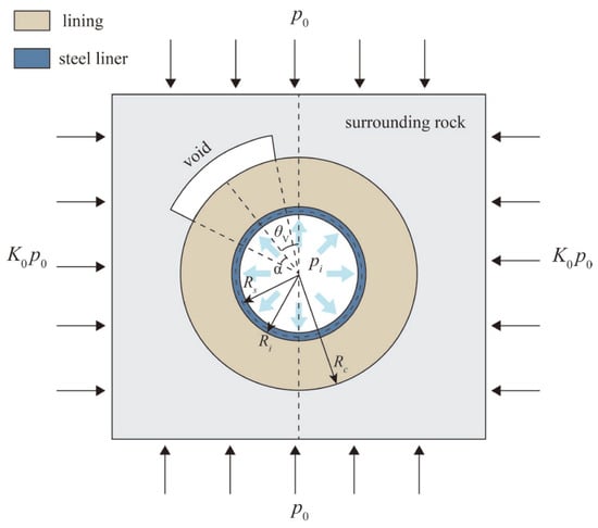
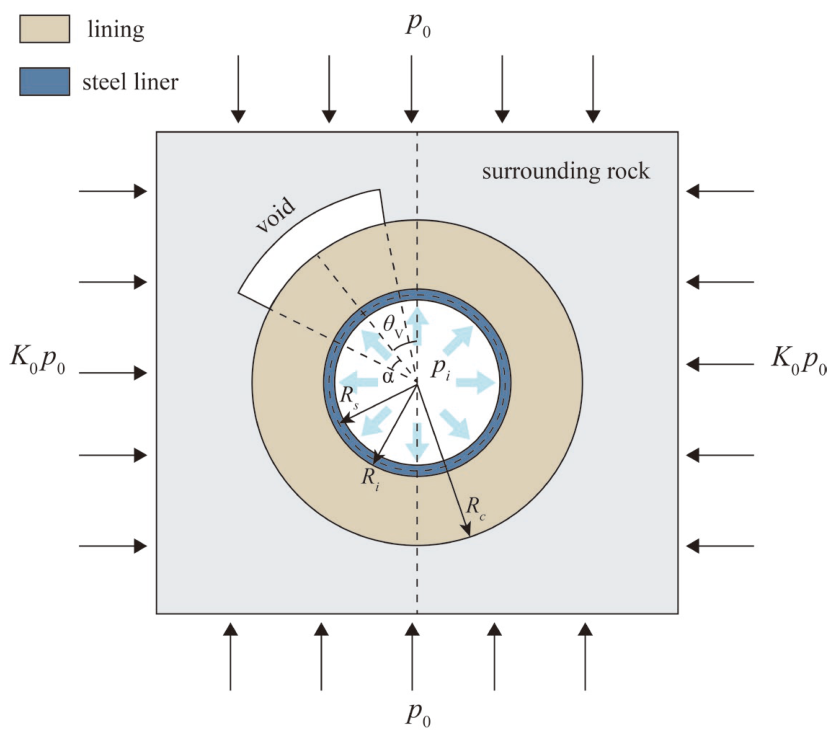
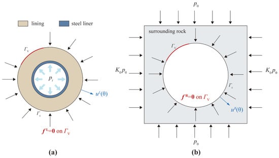
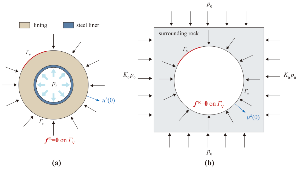
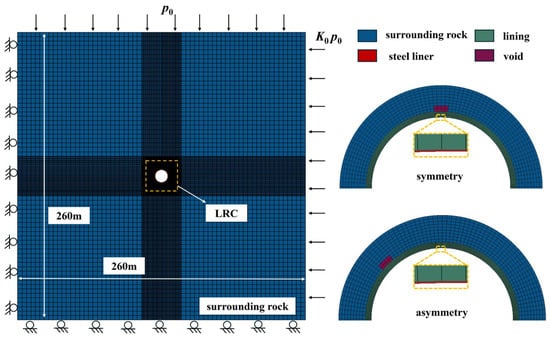
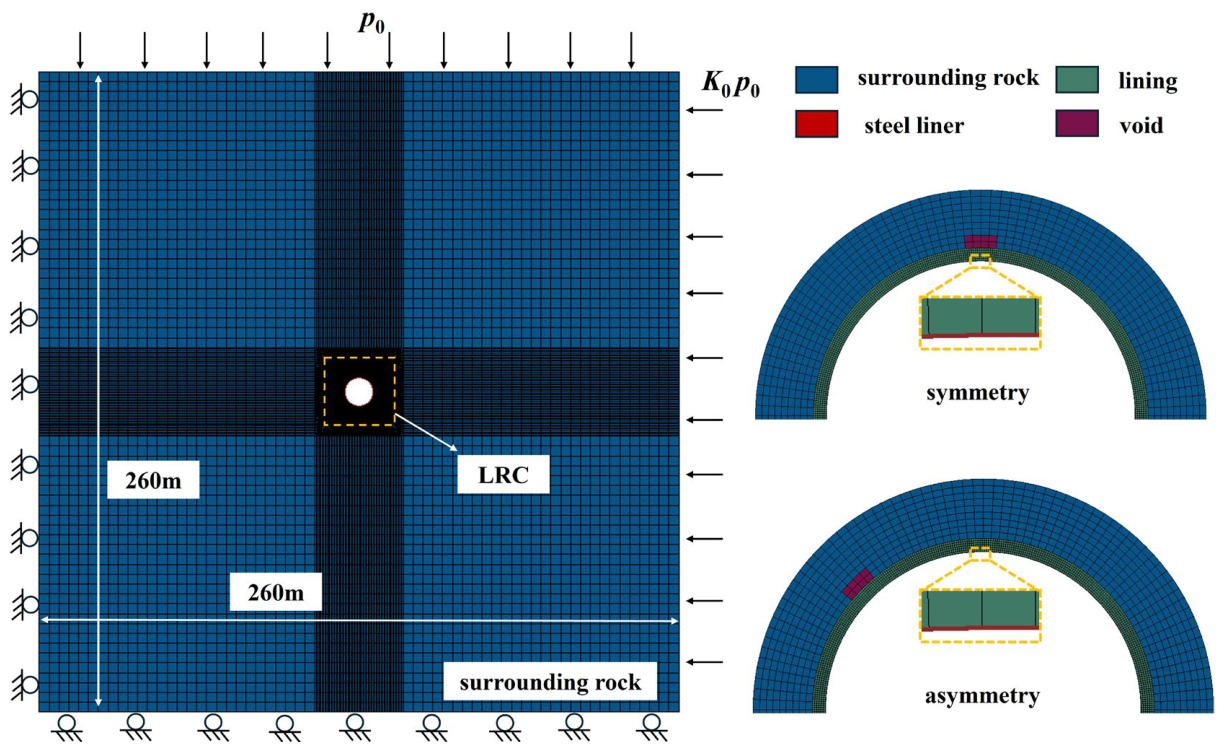
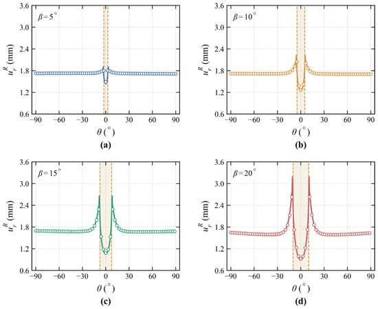
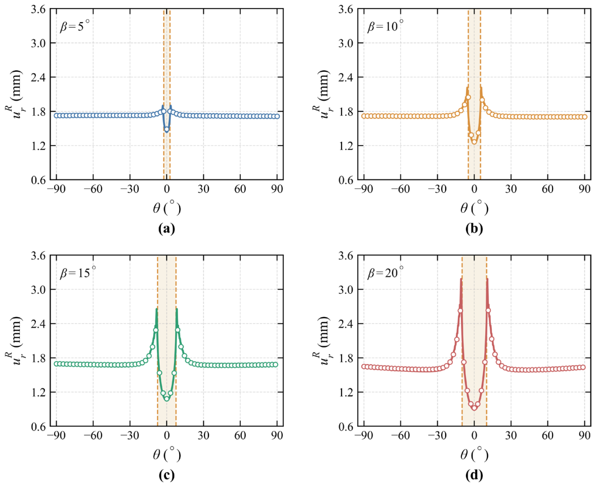
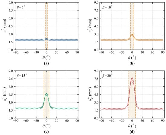
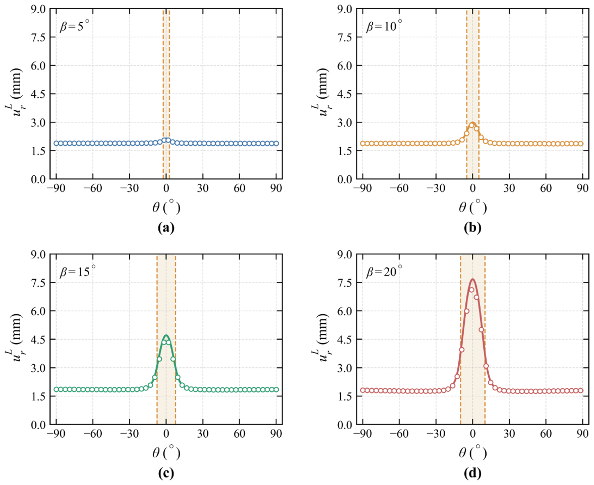
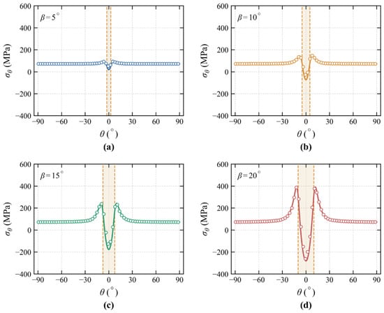
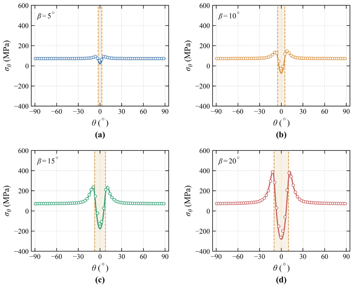
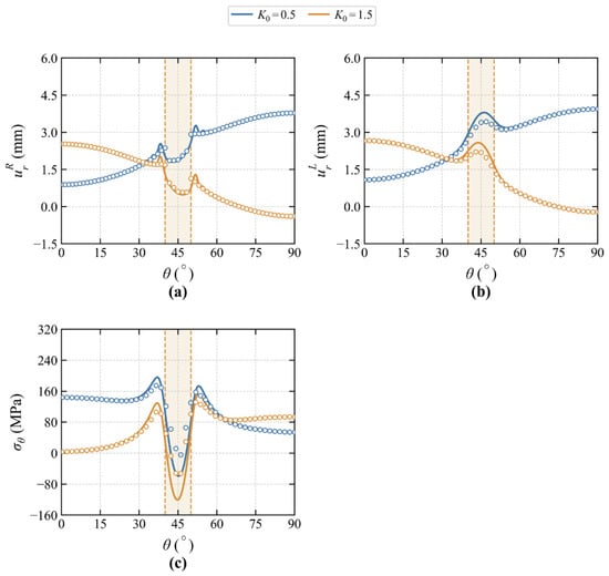
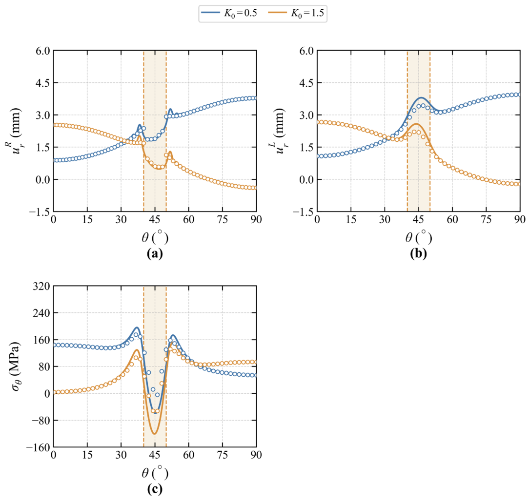
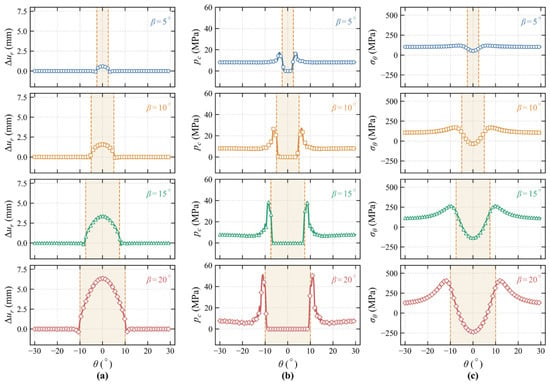
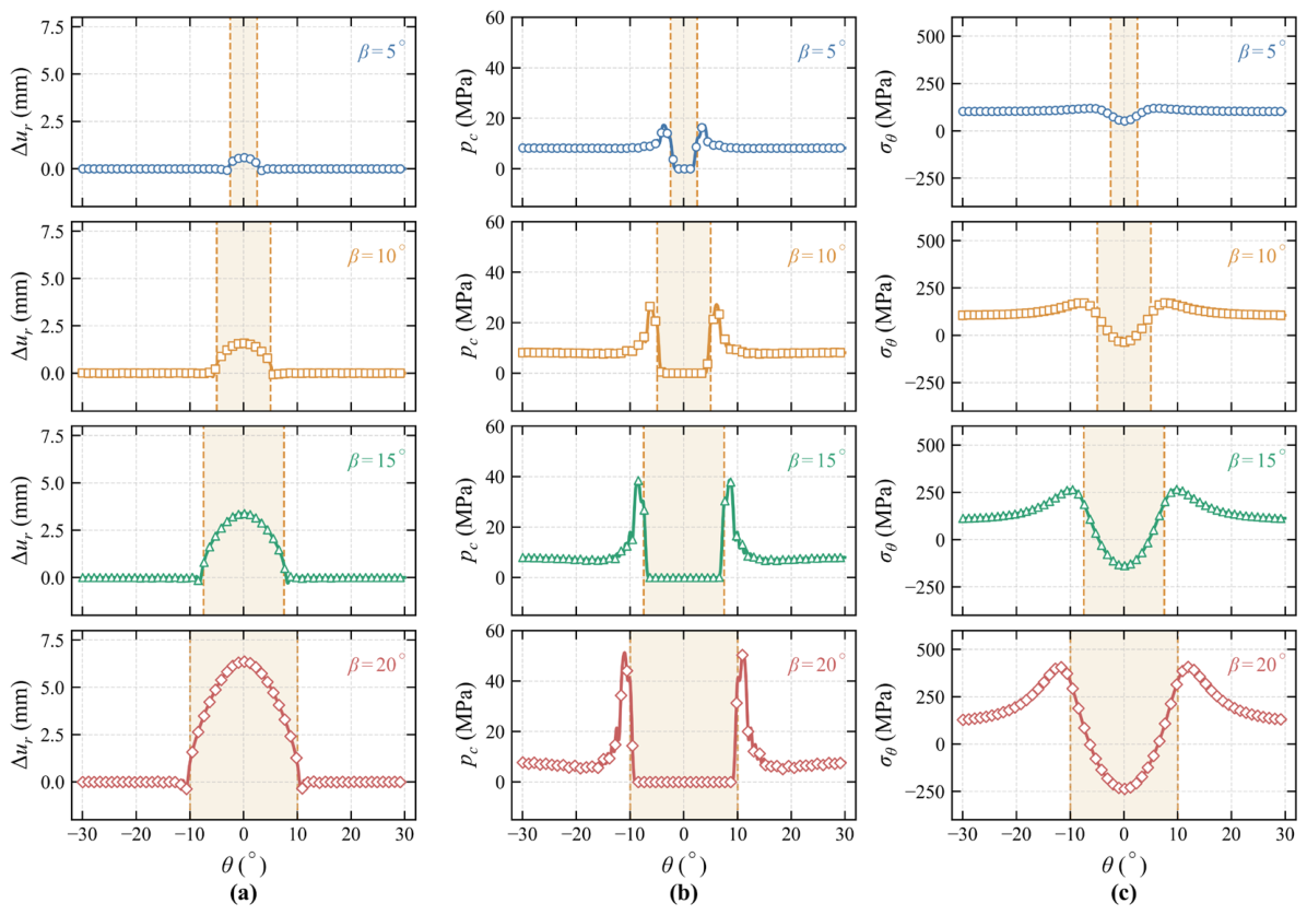
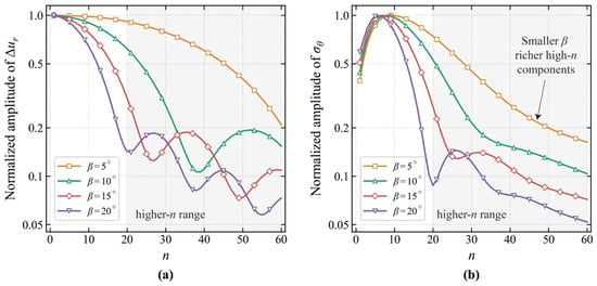
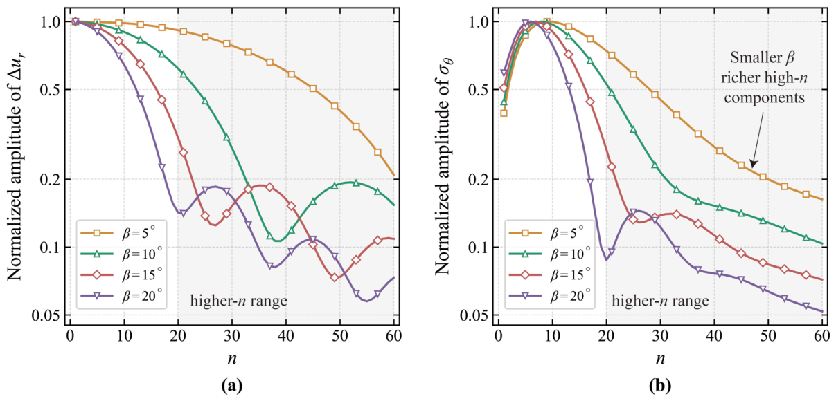
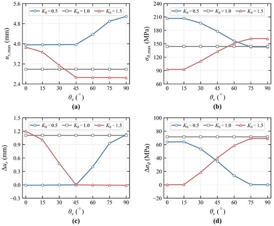
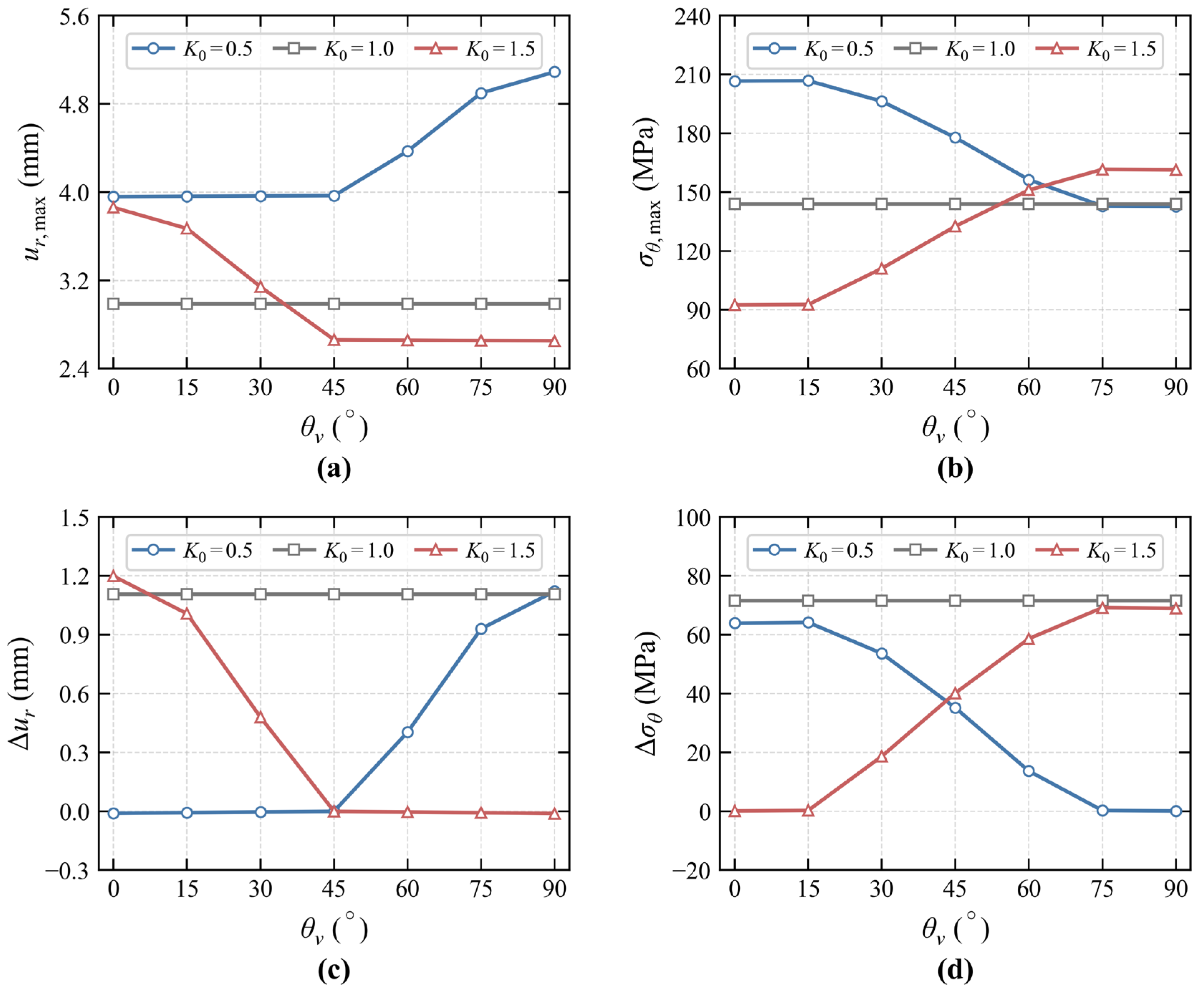
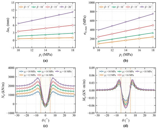
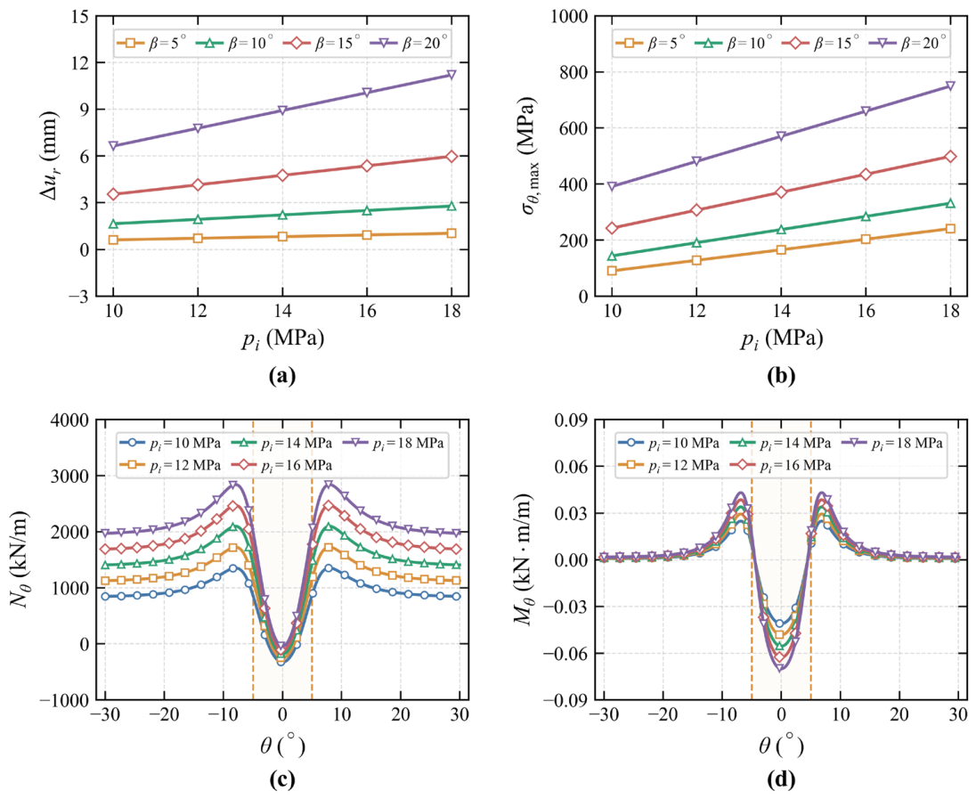
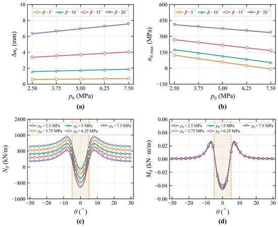
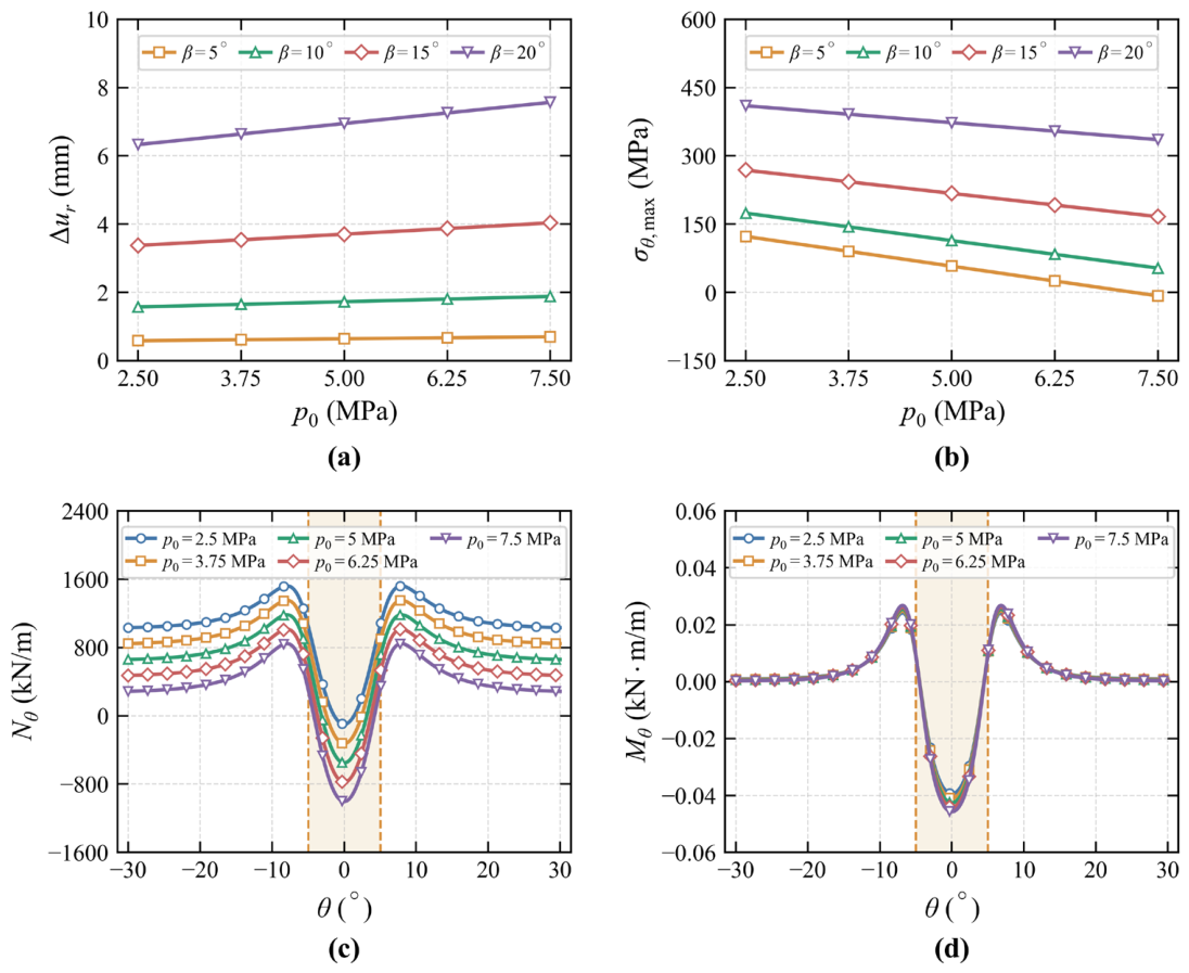
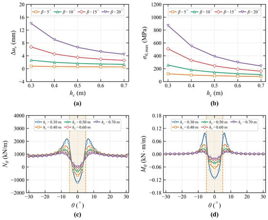
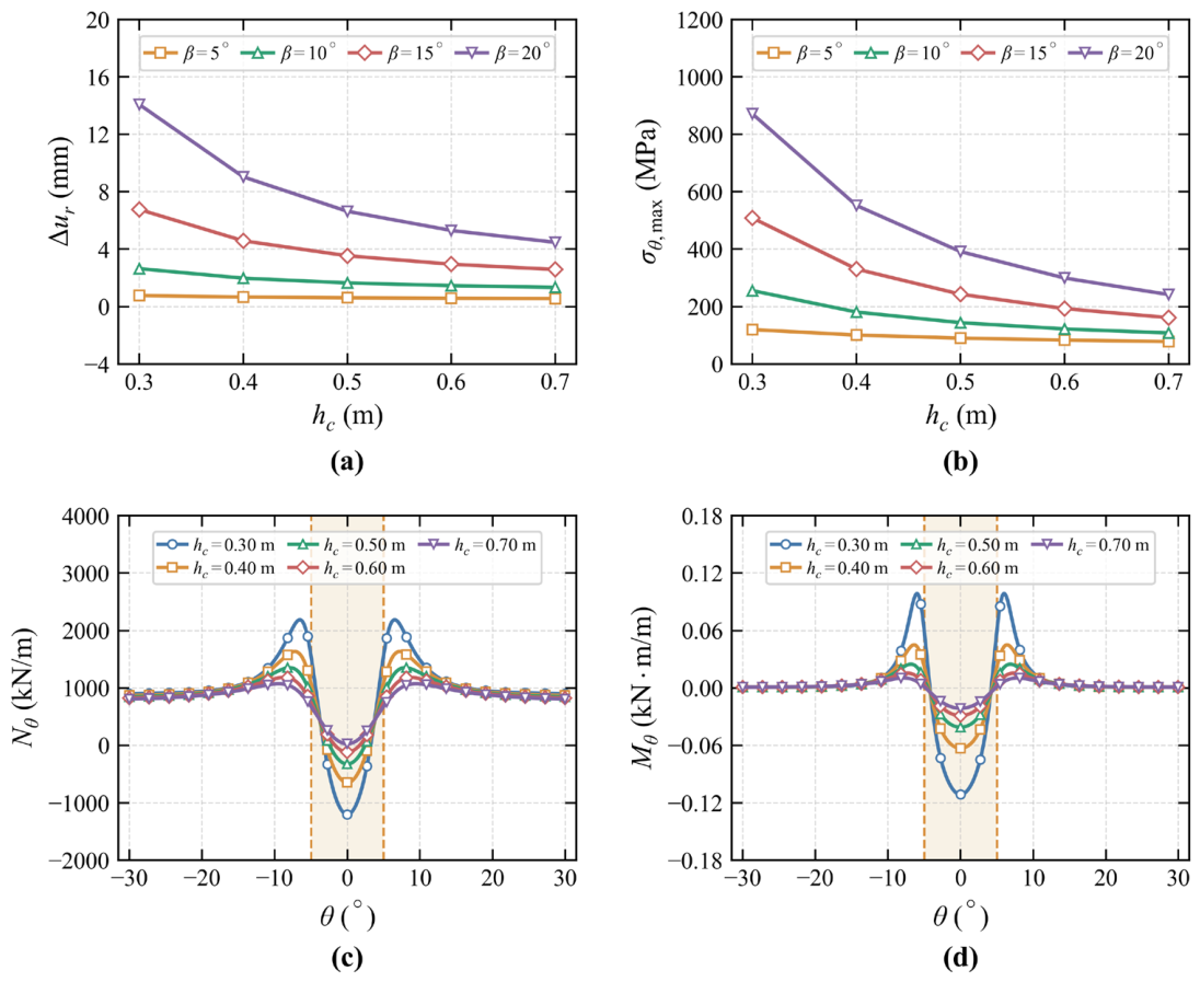
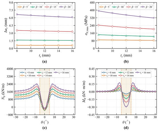
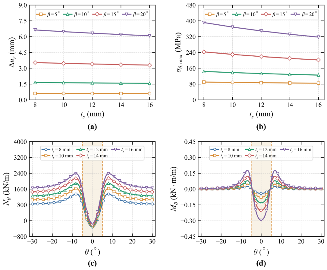
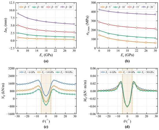
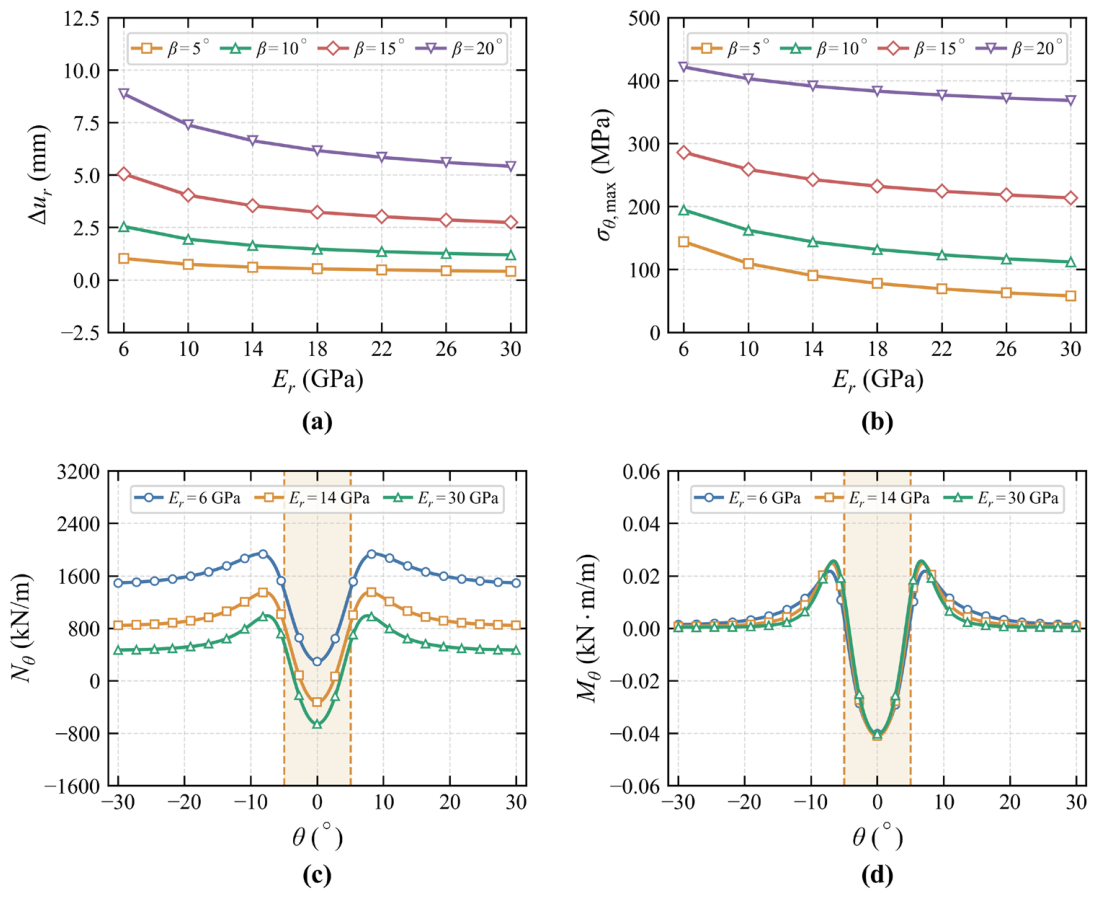

Disclaimer/Publisher’s Note: The statements, opinions and data contained in all publications are solely those of the individual author(s) and contributor(s) and not of MDPI and/or the editor(s). MDPI and/or the editor(s) disclaim responsibility for any injury to people or property resulting from any ideas, methods, instructions or products referred to in the content. |
© 2026 by the authors. Licensee MDPI, Basel, Switzerland. This article is an open access article distributed under the terms and conditions of the Creative Commons Attribution (CC BY) license.