


Abstract
High penetration of inverter-interfaced renewable generation reduces power system inertia and increases the demand for fast plant-level frequency support. This paper proposes a model predictive control (MPC)-based coordinated frequency support strategy for renewable power plants integrating wind power, photovoltaic (PV) generation, and hybrid energy storage systems (HESSs). An equivalent grid frequency response model is first established and combined with aggregated dynamic models of wind, PV, and heterogeneous HESS units to develop a unified control-oriented state-space formulation. In this framework, renewable reserve limits, storage power constraints, and state-of-charge (SoC) dynamics are explicitly incorporated to characterize the time-varying feasible support capability of the plant. On this basis, the coordinated frequency support problem is formulated as a constrained receding-horizon optimization problem, in which frequency deviation suppression, plant-level supplementary power coordination, and HESS energy-state management are considered simultaneously. Simulation studies under step-change and random load disturbances demonstrate the effectiveness of the proposed strategy. Under the representative step-change disturbance, the maximum frequency deviation is limited to approximately p.u., and the frequency rapidly recovers to a steady operating region. Under random load disturbances, the frequency deviation remains bounded within approximately p.u. Moreover, the SoC values of all heterogeneous storage units remain within the prescribed range of 0.3–0.7 p.u. throughout the support process. These results demonstrate that the proposed strategy achieves effective transient frequency support while maintaining coordinated active power allocation and feasible HESS energy-state operation.
1. Introduction
With the rapid integration of wind power, photovoltaic (PV) generation, and hybrid energy storage systems (HESSs), modern power systems are undergoing profound structural changes. The increasing penetration of inverter-interfaced renewable resources reduces system inertia and weakens frequency support capability, making frequency stability more sensitive to active power imbalance disturbances. Meanwhile, the variability and uncertainty of renewable generation further aggravate the difficulty of maintaining stable system frequency under changing operating conditions [1]. In this context, traditional synchronous generators alone can hardly provide sufficient fast frequency support, especially in systems with high renewable penetration [2]. As a result, renewable power plants are no longer expected to operate merely as passive power injection units, but are increasingly required to provide active and coordinated frequency support at the plant level. Therefore, developing an effective coordinated control strategy for renewable power plants with wind, PV, and HESS has become an important issue for enhancing frequency stability in modern power systems [3].
Existing studies have shown that renewable energy plants can actively contribute to frequency regulation in high-renewable power systems, and that coordinated support from wind power, PV generation, and energy storage can effectively improve frequency dynamic performance under low-inertia conditions. In particular, the introduction of hybrid energy storage systems (HESSs) provides additional flexibility for frequency support because different storage technologies exhibit complementary characteristics in response speed, power capability, and energy capacity [4]. Nevertheless, most existing studies mainly focus on system-level frequency support strategies, specific inertia-support schemes, or primary frequency regulation with simplified storage representations [5]. Comparatively less attention has been paid to plant-level coordinated control frameworks that simultaneously consider renewable reserve limits, heterogeneous HESS dynamic characteristics, and SoC-aware active power allocation within a unified control-oriented model [6,7].
Despite these advances, the existing studies can be broadly classified into three categories, each leaving a different limitation for plant-level coordinated frequency support. First, system-level frequency regulation studies mainly focus on inertia enhancement, primary frequency response, or storage-assisted ancillary services [8,9]. These approaches are effective for characterizing the overall frequency response of the grid, but they generally do not resolve the internal allocation of supplementary active power among multiple resources within a renewable power plant. Second, HESS-based studies often emphasize capacity configuration, economic operation, or equivalent storage response [10,11,12,13,14,15]. Although such formulations simplify system-level analysis and planning, representing the HESS as an aggregated resource may obscure differences in response speed, power capability, energy capacity, and SoC evolution among heterogeneous storage units. Third, coordinated renewable-storage control methods have increasingly considered multiple resources [16,17,18,19,20]; however, renewable reserve availability, heterogeneous storage dynamics, SoC-dependent operating constraints, and plant-level active-power allocation are rarely treated simultaneously within a unified control-oriented formulation. Consequently, a gap remains between system-level frequency support studies and a constraint-aware plant-level coordination framework that is sufficiently compact for receding-horizon optimization.
To address the above limitations, this paper develops a constraint-aware plant-level coordinated frequency support framework integrating wind, PV, and heterogeneous HESS [21,22,23]. The framework combines a unified control-oriented model with receding-horizon optimization to coordinate supplementary active power while explicitly accounting for renewable reserve availability, heterogeneous storage dynamics, and SoC-dependent operating constraints.
The main contributions of this paper are summarized as follows: (1) A unified plant-level control-oriented model is established by coupling the equivalent grid-frequency dynamics with the active-power dynamics of wind and PV generation and the unit-level power and SoC dynamics of heterogeneous HESS. Unlike equivalent-storage formulations, this model preserves the dynamic and energy-state heterogeneity of individual storage units while explicitly representing the contribution of each resource to PCC frequency support. (2) A time-varying feasible support region is incorporated directly into the coordinated control formulation by simultaneously considering renewable reserve margins, resource power and ramp-rate limits, HESS charging/discharging constraints, and SoC safety and balancing requirements. This enables supplementary power allocation to adapt to the instantaneous operating capability of individual resources rather than relying on fixed allocation ratios. (3) An incremental receding-horizon MPC formulation is developed and condensed into a constrained quadratic programming problem in which the control-increment sequence constitutes the online decision variable. By eliminating the predicted state trajectory from the independent optimization variables, the resulting formulation provides a compact structure suitable for repeated online solution while retaining the plant-level operating constraints. Compared with fixed-ratio allocation, the proposed MPC framework dynamically updates the contribution of each resource according to its instantaneous feasible operating region. In contrast to conventional local droop-based coordination, the proposed formulation explicitly incorporates renewable reserve availability, heterogeneous HESS dynamics, ramp-rate limits, and SoC constraints into a unified finite-horizon optimization problem.
2. System Modeling of Renewable Power Plants with HESS for Frequency Support
2.1. Overall Structure and Frequency Support Mechanism of the Renewable Power Plant
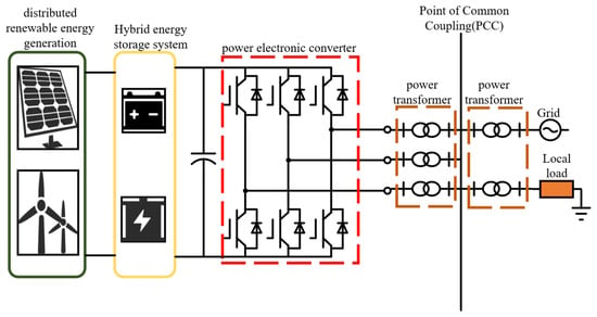
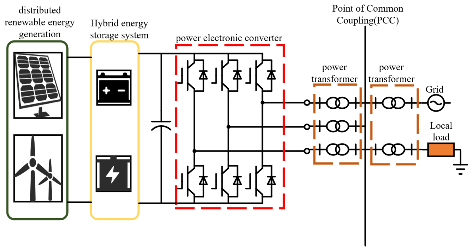
Figure 1 shows the configuration of the grid-connected renewable power plant considered in this work. The plant consists of three main subsystems: a wind turbine cluster, a photovoltaic (PV) array, and a hybrid energy storage system (HESS). The HESS is composed of multiple heterogeneous energy storage units with complementary dynamic and energy-state characteristics. Each subsystem is interfaced to the internal medium-voltage collection bus through dedicated power electronic converters and step-up transformers.
Figure 1.
System topology diagram of a renewable power plant with wind, PV, and heterogeneous HESS.
The wind turbine cluster is connected through a back-to-back converter that regulates active power injection to the collection bus. The PV array is interfaced via a grid-connected inverter, which controls the DC/AC power conversion process. The HESS is connected through bidirectional power electronic converters, enabling coordinated charging and discharging operation for fast grid support. All renewable and storage units are electrically aggregated at the plant-level collection bus and jointly participate in plant-level frequency support through coordinated active power regulation.
The collection bus is connected to the external transmission grid through the point of common coupling (PCC). A local load is also connected at the PCC, representing the internal consumption or nearby demand. The PCC serves as the measurement point for system frequency and power exchange between the renewable plant and the utility grid.
In the renewable power plant considered in this paper, the control objective is to realize coordinated frequency support at the plant level through the joint regulation of wind power, photovoltaic generation, and the hybrid energy storage system (HESS). Specifically, when frequency deviation occurs or an upper-level active power support command is issued, the plant-level controller should rapidly allocate supplementary active power references to different resources, so that the total active power at the point of common coupling (PCC) can effectively respond to system support demand. Meanwhile, since wind and PV units are constrained by available reserve margins and HESS units are subject to heterogeneous dynamic response characteristics, charging/discharging power limits, and energy capacity constraints, the control strategy should not only improve frequency support performance, but also achieve proper power coordination among multiple resources and maintain the state of charge (SoC) of HESS within admissible limits. Therefore, the overall control objective of this study can be summarized into three aspects: frequency support enhancement, coordinated active power allocation, and HESS energy management.
2.2. Equivalent Grid Frequency Response Model
To evaluate the frequency support capability of the renewable power plant at the system level, the external power grid is represented by an equivalent low-order frequency response model that captures the dominant electromechanical dynamics during short-term active power imbalance. Since the objective of this study is plant-level coordinated control rather than detailed network transient simulation, the external grid is approximated as a synchronous-equivalent system with primary frequency regulation capability. This abstraction preserves the essential relationship between active power imbalance and system frequency deviation while maintaining a tractable structure for subsequent controller design.
Let denote the frequency deviation of the external grid from its nominal value. The equivalent frequency dynamics are described by the swing equation defined below:
where represents the equivalent inertia constant of the external grid, represents the equivalent damping coefficient, represents the incremental mechanical power provided by the conventional primary frequency regulation of the external grid, represents the supplementary active power injected by the renewable power plant at the point of common coupling (PCC), represents the active load disturbance and represents the system frequency deviation.
Equation (1) indicates that the system frequency variation is jointly determined by equivalent inertia, load damping, conventional primary regulation, load disturbance, and the active power support delivered by the renewable power plant.
For the external grid, the aggregated primary frequency response is modeled by an equivalent droop characteristic. Thus, the mechanical power increment can be expressed as
where represents the equivalent droop coefficient of the external grid. This term reflects the conventional governor-based primary regulation effect at the system level and provides a simple yet effective representation of the inherent frequency stabilization capability of the synchronous-equivalent grid.
Substituting (2) into (1), the grid frequency dynamics can be written in the standard state form as
Equation (3) explicitly shows that the frequency deviation dynamics are directly influenced by the supplementary active power delivered by the renewable power plant at the PCC. Therefore, once the plant-level support power is determined, its impact on the external grid frequency can be evaluated through the equivalent frequency response model. It should be emphasized that the role of the renewable power plant in this paper is not to replace the conventional primary regulation of the grid, but to provide fast supplementary active power support through coordinated regulation of wind power, photovoltaic generation, and the hybrid energy storage system. Accordingly, the plant-level support power is defined as the net active power increment injected at the PCC, which will be decomposed in the next section into wind, PV, and HESS contributions. In other words,
where , and represent the supplementary active power outputs of the aggregated wind subsystem, the aggregated PV subsystem, and the i-th storage unit in the HESS, respectively.
For later controller design, the external grid frequency response model can be interpreted as a single-state subsystem driven by two external inputs: the plant-level support power and the load disturbance. Defining and Equation (3) can be compactly expressed as
with
This representation facilitates the subsequent formulation of the overall plant-level state-space model by allowing the grid frequency dynamics to be directly coupled with the aggregated dynamic models of wind, PV, and HESS resources.
In summary, the equivalent grid frequency response model established in this section provides a low-order but physically meaningful description of the external system dynamics relevant to plant-level frequency support. By introducing the plant-level active power support explicitly into the frequency state equation, the model forms the external dynamic interface for the coordinated control problem studied in this paper. On this basis, the next section develops the aggregated dynamic models of wind power, photovoltaic generation, and the hybrid energy storage system and further derives the plant-level active power coupling relationship.
2.3. Aggregated Dynamic Models of Wind, PV, and HESS
To develop a control-oriented plant-level dynamic model, the wind, photovoltaic, and hybrid energy storage subsystems are represented in aggregated form. Since this study focuses on coordinated frequency support at the plant level, detailed converter switching behavior and device-level electromagnetic transients are neglected. Instead, wind and PV units are modeled by low-order active power dynamics, while the HESS is described by heterogeneous storage units with distinct dynamic and energy-state characteristics. This formulation retains the essential dynamics for frequency support analysis while ensuring tractability for controller design. Accordingly, the proposed model does not resolve semiconductor-level switching processes or soft-switching conditions such as ZVS/ZCS; these converter-level phenomena are outside the scope of the present plant-level frequency-support analysis.
2.3.1. Wind and PV Aggregated Models
In the renewable power plant, both wind turbines and photovoltaic units are interfaced through power electronic converters and coordinated by the plant-level supervisory controller. During frequency support operation, the plant controller generates supplementary active power commands that are superimposed on the scheduled power references of wind and PV subsystems. Accordingly, the wind and PV active-power responses are represented by first-order models.
Let the total active power output of the aggregated wind subsystem be expressed as
where represents the scheduled wind power and represents the supplementary active power contribution for frequency support. Similarly, the total active power output of the aggregated PV subsystem is defined as
where represents the scheduled PV power and represents the corresponding supplementary active power contribution.
The dynamic response of the aggregated wind subsystem is modeled as
where represents the effective response time constant of the wind subsystem and represents the supplementary active power command assigned by the plant-level controller.
The corresponding state equation is
Combining the physical power limits and reserve limits, the effective feasible regions of the supplementary active power outputs are obtained as
In this study, the upward reserves of wind and PV are obtained through de-rated or curtailed operation. Let and denote the instantaneous available powers of the wind and PV subsystems, respectively. The corresponding upward reserve margins are defined as
Here, the available wind and PV powers can be estimated from the current wind and irradiance conditions, respectively, whereas and are the scheduled de-rated operating powers. Therefore, and are time-varying quantities that are updated according to the current renewable operating conditions and supplied to the plant-level MPC as available support constraints.
The above equations show that the wind and PV subsystems can be represented as time-varying constrained active power sources, with frequency support capability determined by response dynamics, operating point, and reserve availability. Hence, fixed-ratio allocation is generally inadequate for plant-level coordination under variable renewable conditions. The first-order, reserve-constrained modeling framework is extended to a broader coordinated control setting.
2.3.2. HESS Dynamic Model and SoC Evolution
Compared with wind and PV subsystems, the energy storage system provides faster and more accurate active power regulation capability. However, practical plant-level storage systems are often made up of multiple heterogeneous storage units rather than a single uniform battery block. Different storage units may exhibit significantly different response speeds, charging/discharging power limits, and energy capacities. This paper models the HESS as a set of M heterogeneous storage units with explicit dynamic and energy-state descriptions.
Let the total power output of the i-th storage unit be written as
where represents the scheduled or baseline power of the i-th storage unit and represents the supplementary active power used for frequency support.
The dynamic response of the i-th storage unit is described by the first-order model
where represents the effective response time constant of the i-th storage unit, and represents the active power command generated by the plant-level controller. It should be noted that the common first-order structure in (14) does not imply identical physical characteristics among different storage technologies. It is adopted as a control-oriented reduced-order representation of their dominant active-power dynamics. Their heterogeneity is explicitly characterized through different response time constants, power limits, energy capacities, and SoC constraints. Considering the charging/discharging power limits and reserve constraints of the i-th storage unit, the admissible supplementary power region can be written as
The reserve variables represent the currently available upward and downward active-power regulation margins of the corresponding resources. For the wind and PV subsystems, the upward reserves and are determined by the difference between the instantaneous available renewable power and the scheduled de-rated operating power, whereas and denote the maximum permissible active-power reductions from the scheduled operating points. For the i-th storage unit, and represent the available discharge and charge regulation margins, respectively. These storage reserve margins are determined by the current operating power, the charging/discharging power limits, and the SoC-dependent feasible operating range. All reserve variables are updated according to the current operating conditions and are supplied to the plant-level MPC as time-varying constraints. To characterize the energy state of each storage unit, the state of charge of the i-th unit is denoted by . The SoC evolution is directly related to the storage power and the rated energy capacity. Thus,
where is the rated energy capacity of the i-th storage unit. For the control-oriented model considered in this study, the charge/discharge efficiency is assumed to be unity and conversion losses are neglected. This simplification preserves the linearity of the SoC dynamics and facilitates their direct incorporation into the MPC state-space formulation.
The SoC of each storage unit must remain within its admissible operating interval,
In addition to individual SoC safety bounds, coordinated HESS operation requires the energy states of different storage units to remain reasonably balanced. To quantify this requirement, the average SoC of the HESS is defined as
Then, the SoC imbalance index is defined as
Equations (14)–(19) indicate that the HESS cannot be treated as a single homogeneous actuator when plant-level frequency support is considered. Its overall dynamic and energy-state behavior depends on the heterogeneous properties of individual storage units.
2.3.3. Plant-Level Active Power Coupling Relationship
Although wind, PV, and HESS subsystems are modeled individually, they are physically aggregated at the plant level and jointly determine the active power exchanged with the external grid at the PCC. Therefore, a plant-level active power coupling relationship is required to link the subsystem-level models developed above with the external frequency response model.
The total active power output of the renewable power plant at the PCC is given by
PCC power can be decomposed into a baseline component and a supplementary support component as
where
is the baseline plant output, and
is the total supplementary active power provided by the plant for frequency support.
At the plant level, the supervisory controller generates a total additional support demand , which is dynamically allocated to wind, photovoltaic, and HESS. Therefore, the plant-level command decomposition can be expressed as
Since each subsystem is subject to its own dynamic response and operational constraints, the actual supplementary support power is not instantaneously equal to , but evolves according to the subsystem dynamics given in Section 2.3.1 and Section 2.3.2. In ideal steady tracking, one has approximately
It should be noted that the approximation in (25) is valid only under steady-state or sufficiently slow-varying tracking conditions. During transient operation, the actual supplementary power response is governed by the subsystem dynamics and is limited by the response time constants , , and . By combining (23) with the equivalent grid frequency response model in Section 2.2, the system frequency dynamics can be rewritten as
Equation (26) reveals that plant-level frequency support is fundamentally a multi-resource active power coordination problem. Wind and PV support contributions are limited by available reserves and output margins, while HESS contributions are additionally constrained by dynamic response differences and SoC states. As a result, the plant-level support capability is a time-varying feasible region jointly determined by the operating conditions of all constituent resources. This coupling relationship provides the direct bridge between the subsystem-level dynamic models and the unified state-space formulation that will be developed in the following sections.
2.4. Power, Reserve, and SoC Constraints
To ensure the practical implementability of plant-level frequency support, the supplementary active power commands assigned to wind, PV, and HESS units must satisfy multiple operational constraints. These constraints arise from physical power limits, available reserve margins, charging/discharging capability, energy-state boundaries, and plant-level coordination requirements. Although the subsystem models established in Section 2.3 already imply some of these boundaries, they are collected and reformulated here in a unified manner so that they can be directly incorporated into the subsequent controller design.
Based on the feasible regions derived for the wind, PV, and HESS subsystems in Section 2.3, the plant-level coordinated controller is further subject to SoC, ramp-rate, and aggregated support constraints. In addition to power constraints, the energy state of each storage unit must remain within its allowable SoC range,
This constraint is particularly important in plant-level frequency support, because the instantaneous power flexibility of a storage unit does not necessarily imply sustained support capability unless sufficient available energy remains, where SoC safety and energy-state management are treated as essential components of coordinated control.
The SoC imbalance among heterogeneous storage units can be characterized by the inequality
where denotes the allowable SoC dispersion. In the present MPC formulation, the SoC imbalance is primarily treated through the penalty term in the objective function rather than enforced as strict equalization. This formulation is intended to avoid excessive divergence among heterogeneous storage units while preserving their differentiated dynamic roles.
Besides the static power and energy-state limits, the dynamic adjustment rates of plant resources must also remain within feasible bounds. For the wind, PV, and HESS subsystems, the ramp-rate constraints can be written as
These ramp-rate constraints prevent unrealistically abrupt active power changes and improve the physical consistency of the control commands issued by the plant-level coordinator. They are especially relevant when multiple fast and slow resources coexist in a coordinated frequency support framework.
At the plant level, the total supplementary support power is defined as
and must satisfy the aggregated feasible interval
where the upper and lower support limits are obtained from the summation of the subsystem support margins, as already derived in Section 2.3.3. Equation (31) indicates that the plant-level support capability is not fixed, but varies with renewable operating conditions, reserve availability, HESS power margins, and SoC states. Therefore, plant-level control should be viewed as a constrained multi-resource coordination problem over a time-varying feasible set rather than a simple command-tracking task.
For later controller formulation, it is convenient to collect the subsystem control inputs into a plant-level control vector
Then, the admissible input set can be compactly written as
where is determined by the subsystem feasible regions in Section 2.3 together with the SoC, ramp-rate, and aggregated support constraints in (27)–(33). In other words, represents the set of all plant-level control commands that are physically feasible for the coordinated wind–PV–HESS system.
If the model is later discretized with sampling interval , the ramp-rate constraints can be written in discrete-time form as
These expressions are particularly useful for the construction of finite-horizon constrained optimization problems in subsequent controller design.
In summary, the operational constraints of the renewable power plant include four closely coupled categories: renewable generation output and reserve limits, HESS charging/discharging power limits, HESS SoC safety and imbalance-mitigation requirements, and plant-level support capability bounds. Collectively, these constraints define the feasible region of coordinated frequency support actions. By explicitly incorporating them into the plant-level model, the control strategy can ensure that the generated active power support commands remain physically meaningful, dynamically achievable, and compatible with the long-term energy management needs of the HESS.
2.5. Unified State-Space Formulation for Controller Design
Based on the subsystem models and operational constraints established above, this section integrates the grid frequency, renewable generation, and HESS dynamics into a unified state-space representation for MPC design.
According to Section 2.2, the external grid frequency dynamics are determined by the plant-level supplementary active power injected at the PCC. Combining the subsystem support contributions derived in Section 2.3, the plant-level supplementary power can be written as
Therefore, the system frequency deviation, the aggregated wind and PV power responses, the supplementary power outputs of heterogeneous storage units, and their corresponding SoC states are selected as the overall system states. The continuous-time state vector is defined as
and the control input vector is defined as
Let the load disturbance be denoted by . Then, the overall plant-level dynamics can be compactly expressed as
where and G are the system, input, and disturbance matrices, respectively, and denotes the offset term associated with the baseline operating point of the storage units. If the baseline power schedule is treated as known or slowly varying, can be regarded as a known exogenous term. This compact form directly reflects the coupling among external grid frequency deviation, renewable power support, and HESS energy-state evolution.
For controller design, the output vector may be selected as
where a representative output set includes the system frequency deviation, the plant-level supplementary support power, and the SoC states of all heterogeneous storage units. This output definition is sufficient for evaluating both dynamic frequency support performance and HESS energy management behavior.
If a digital controller is implemented, the continuous-time model in (38) can be discretized with sampling interval as
with the corresponding output equation
The admissible operating conditions summarized in Section 2.4 can then be imposed in the compact form
where and denote the state and input constraint sets determined by renewable output limits, reserve margins, HESS charging/discharging bounds, SoC safety intervals, and plant-level support capability constraints.
In summary, the unified state-space model established in this section provides a compact mathematical foundation for subsequent controller design. By integrating the external frequency response dynamics, renewable subsystem power dynamics, and heterogeneous HESS SoC evolution into a single representation, the coordinated frequency support problem of the renewable power plant is transformed into a tractable constrained control problem suitable for optimization-based or learning-based plant-level coordination strategies.
3. Plant-Level Coordinated Frequency Support Control Design
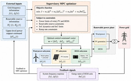
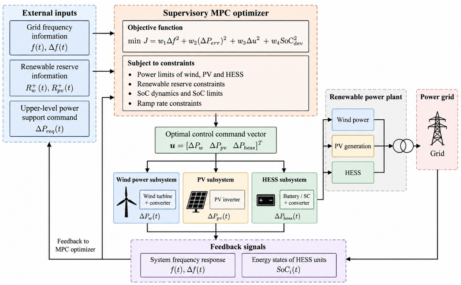
As shown in Figure 2, the supervisory MPC coordinates wind, PV, and HESS according to the frequency response, renewable reserve availability, and HESS energy states. The optimal control commands are obtained under the defined power, reserve, ramp-rate, and SoC constraints, while frequency and SoC measurements are fed back for receding-horizon optimization.
Figure 2.
Overall architecture of the proposed MPC-based coordinated frequency support strategy.
Based on the unified state-space model established in Section 2, the coordinated frequency support problem of the renewable power plant can be formulated as a constrained multivariable control problem. The essential task of the plant-level controller is to determine the supplementary active power commands for wind power, photovoltaic generation, and the heterogeneous hybrid energy storage system (HESS) in real time, such that the plant-level support power can effectively mitigate system frequency deviations while satisfying renewable reserve limits, storage power bounds, and SoC-related operational constraints. This section first formulates the control objective and the associated constrained optimization problem. Then, a model predictive control (MPC)-based coordinated control strategy is developed, followed by the receding-horizon implementation procedure.
3.1. Problem Formulation and Control Objective
The plant-level supplementary support power injected at the PCC is given by
and average state of charge of the HESS is defined as
To quantify the plant-level control performance, the supplementary power tracking error and the SoC imbalance index are defined as follows: Here, denotes the plant-level supplementary active-power support reference over the prediction horizon, provided by the upper-level grid operator or plant supervisory controller according to the system-level frequency-support requirement. It is treated as an exogenous time-varying reference rather than an additional system state or optimization variable.
where denotes the plant-level supplementary power tracking error and denotes the HESS SoC imbalance index. The tracking error represents the mismatch between the plant-level supplementary power requested by the upper-level controller and the supplementary power predicted to be delivered at the PCC. Accordingly, the coordinated control objective is formulated as
where and are the prediction and control horizons; , , and are weighting coefficients; and R is the control increment weighting matrix. The first term penalizes frequency deviation, the second term enforces plant-level supplementary power tracking, the third term suppresses excessive SoC imbalance among heterogeneous storage units, and the last term limits overly aggressive control variations. Through the supplementary power tracking term, the requested plant-level support reference directly influences the optimal control allocation among wind, PV, and HESS, while the resulting control actions remain subject to the corresponding operational constraints. The MPC weights are selected according to the relative importance of frequency regulation, power tracking, SoC coordination, and control smoothness; weight-sensitivity analysis is not considered in this study.
Therefore, the plant-level coordinated frequency support problem can be posed as the following constrained finite-horizon optimization problem:
subject to
where and denote the admissible state and input sets determined by the renewable output limits, reserve margins, HESS charging/discharging bounds, SoC safety intervals, and plant-level support capability constraints defined in Section 2.4.
When renewable reserve limits and HESS SoC constraints become simultaneously active, the admissible control actions are restricted to the intersection of the corresponding feasible sets. The operational constraints are treated as hard constraints, whereas the required plant-level support power is incorporated through the tracking term in the objective function. Therefore, when the requested support exceeds the currently available capability, the controller minimizes the tracking error within the feasible region rather than violating the reserve or SoC limits. When a storage unit approaches an SoC boundary, the control action that would further violate the corresponding SoC limit is excluded from its admissible input set, and the support demand is redistributed among the remaining feasible resources. Because the support demand is included as a tracking objective rather than a hard equality constraint, constraint satisfaction is prioritized over exact tracking. Therefore, feasibility is maintained as long as the updated admissible control set remains non-empty. A formal global proof of recursive feasibility is beyond the scope of the present formulation.
In this way, the coordinated frequency support task of the renewable power plant is formulated as a constrained multivariable optimal control problem, in which frequency support performance, plant-level active power coordination, and HESS energy management are considered simultaneously.
3.2. Plant-Level Coordinated Control Strategy Design
Building upon the plant-level model and constrained optimal formulation established in the previous sections, this section develops a coordinated control strategy based on model predictive control (MPC). By optimizing the supplementary active power allocation among wind, PV, and heterogeneous HESS units over a finite prediction horizon, the proposed strategy implements a receding-horizon mechanism. This enables the plant-level controller to dynamically adjust support commands according to evolving system states, renewable reserve availability, and HESS energy conditions.
3.2.1. Prediction Model for Receding-Horizon Control
Starting from the discrete-time state-space model
the control increment is introduced as
Then, the future control sequence over the control horizon can be written as
Using the standard incremental formulation, the predicted state trajectory over the prediction horizon can be compactly expressed as
where
Similarly, the predicted output sequence is written as
Equations (52)–(54) provide the finite-horizon prediction model required for coordinated optimization. They explicitly characterize how future frequency deviation, plant-level support power, and HESS SoC states evolve as functions of the current operating condition and future control increments.
3.2.2. Condensed Optimization Formulation
Based on the objective function defined in Section 3.1, the finite-horizon control problem can be transformed into the following condensed quadratic form:
where is the Hessian matrix associated with the weighting terms in the objective function, and is the gradient vector determined by the current state, the required support power, and the predicted disturbance.
The optimization is subject to the plant-level operational constraints, which can be compactly written as
where and collect the renewable output limits, reserve margins, HESS charging/discharging bounds, SoC safety constraints, and plant-level support capability constraints, while SoC imbalance is penalized through the objective function. The condensed quadratic program is strictly convex under non-negative performance weights and a positive-definite control-increment weighting matrix, ensuring a unique optimum whenever the feasible set is non-empty. Physical operating limits are imposed as hard constraints, whereas support-power tracking is optimized within the feasible region. Since no terminal stability condition is introduced, asymptotic closed-loop stability is not formally claimed and is instead assessed through the disturbance studies in Section 4. In the present formulation, a terminal constraint is not introduced in order to retain a compact online optimization structure and to avoid constructing a terminal invariant set for the time-varying operating conditions and resource constraints considered here. A formal stability guarantee would generally require additional assumptions and terminal ingredients, such as stabilizability of the prediction model, recursive feasibility, a suitable Lyapunov-type cost condition, and/or an invariant terminal region with an associated local stabilizing controller. It should also be noted that MPC formulations without explicit terminal constraints can still admit stability guarantees under appropriate controllability conditions, sufficiently long prediction horizons, or relaxed Lyapunov conditions, as demonstrated in previous studies [24]. A rigorous stability analysis under such conditions is beyond the scope of the present work and will be considered in future research.
In this way, the coordinated frequency support problem is converted into a constrained quadratic programming problem over the prediction horizon. By substituting the predicted state and output trajectories into the objective function and constraints, these trajectories do not need to be treated as independent online decision variables. The resulting optimization is therefore expressed only with respect to the control-increment sequence over the control horizon. This condensed formulation reduces the number of explicit online optimization variables compared with a full-space state-input formulation and yields a standard constrained quadratic programming structure, which is advantageous for repeated receding-horizon implementation. The underlying constraint sets remain those defined from the plant-level feasible region in Section 2.4.
3.2.3. Receding-Horizon Implementation
At each sampling instant k, the plant-level controller performs the following operations: First, the current state is measured or estimated, including the grid frequency deviation, the supplementary power states of renewable subsystems and the SoC states of all heterogeneous storage units. Second, the prediction model and the corresponding constraint sets are updated according to the current operating point and reserve availability. Third, the condensed quadratic programming problem in (56)–(57) is solved to obtain the optimal control increment sequence:
Only the first control increment is applied to the plant,
while the remaining predicted control moves are discarded. At the next sampling instant, the optimization is repeated using updated measurements. This receding-horizon mechanism enables continuous and constraint-aware coordination of wind, PV, and HESS support actions under changing frequency conditions and time-varying resource availability. Compared with fixed-ratio allocation, the proposed strategy provides more flexible and physically consistent plant-level coordination.
3.3. Solution Procedure and Implementation Flow
The overall online implementation procedure of the proposed MPC-based coordinated frequency support strategy is summarized in Algorithm 1.
| Algorithm 1 Online Receding-Horizon Coordinated Frequency Support. |
Require: Plant-level model, constraint sets, prediction horizon , control horizon
|
In summary, the proposed implementation framework combines unified state-space modeling, finite-horizon prediction, and rolling constrained optimization into a single online coordinated control architecture. This structure enables dynamic supplementary power allocation among wind, PV, and heterogeneous HESS units while maintaining feasible operation and acceptable HESS energy-state distribution.
4. Simulation Studies
4.1. System Configuration
Practical application scenario: The studied system represents a grid-connected renewable power plant with wind power, PV generation, and a heterogeneous HESS, which can be viewed as a typical large-scale renewable energy station connected to a weak or low-inertia regional grid. In practical operation, such a plant is usually required to follow scheduled power dispatch under normal conditions, while also responding to fast frequency support requests issued by the grid operator during active power imbalance events. The local load connected at the PCC can be regarded as nearby industrial demand or station-service load, and the considered disturbances correspond to sudden load pickup, load shedding, or stochastic net-load fluctuations in the interconnected grid. Under these circumstances, the coordinated utilization of wind, PV, and heterogeneous storage resources becomes essential for improving transient frequency response and maintaining acceptable HESS energy-state behavior. The simulation cases in this section are therefore designed to reflect typical practical operating conditions of renewable power plants participating in grid frequency support. Communication delays, measurement noise, and forecasting errors are neglected in the present simulations to focus on the plant-level coordination mechanism.
In this section, we conduct simulations to verify the effectiveness of the proposed plant-level coordinated frequency support strategy. The simulations are performed with MATLAB/Simulink (R2023a) software on a PC with 8 CPUs (Intel Core i5-13600KF 3.5 GHz) and 32 Gb RAM. The studied system consists of an aggregated wind power subsystem, an aggregated photovoltaic subsystem, and a heterogeneous hybrid energy storage system (HESS), all connected to the external power grid through the point of common coupling (PCC). The external grid is represented by the equivalent low-order frequency response model developed in Section 2.2, while the renewable plant is modeled by the aggregated dynamic equations derived in Section 2.3, Section 2.4 and Section 2.5.
The total system base capacity is set to 1000 MW. The renewable power plant comprises 150 MW of wind power, 150 MW of photovoltaic generation, and 50 MW of energy storage. For the equivalent grid model, the inertia constant, damping coefficient, and droop coefficient are selected as , , and , respectively. The effective active power response time constants of the wind and PV subsystems are set to 2 s and 1 s, respectively.
To reflect the heterogeneous energy-state characteristics of HESS in coordinated frequency support, the storage subsystem is not modeled as a single BESS block. Instead, a representative heterogeneous configuration composed of four storage unit types is adopted, namely super-capacitor energy storage (SCES), vanadium redox flow battery energy storage (VRFBES), lead-acid battery energy storage (LABES), and lithium-iron-phosphate battery energy storage (LIPBES). During simulation, both renewable generation subsystems provide supplementary active power support within their available reserve ranges, while the HESS supplies fast bidirectional power compensation subject to unit-wise power and SoC constraints. The main parameters of the equivalent grid and renewable plant are summarized in Table 1, and the adopted heterogeneous HESS parameters are listed in Table 2. The power limits in Table 2 represent the available supplementary active-power ranges of the individual HESS units for frequency-support operation. Unless otherwise specified, the per-unit quantities of the HESS units in Table 2 are defined on the system base power of 1000 MW. The energy capacity values are expressed in on the same system base. The aggregate limits in Table 2 correspond to approximately MW and MW on the 1000 MW system base and represent the available frequency-support margins rather than the 50 MW installed HESS rating.
Table 1.
Main parameters of the equivalent grid and renewable plant.
Table 2.
Representative parameters adopted for the heterogeneous energy storage units in the present simulations.
Accordingly, the actual power and energy ratings of individual storage units can be obtained by converting the corresponding per-unit values with respect to the system base. The HESS has a total installed power capacity of 50 MW, while the power limits listed in Table 2 denote the available supplementary active-power ranges of the individual storage units for frequency-support operation rather than their installed ratings.
4.2. Simulation Results
4.2.1. Results Under Step-Change Load Disturbances
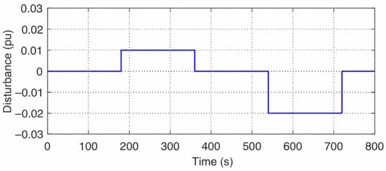
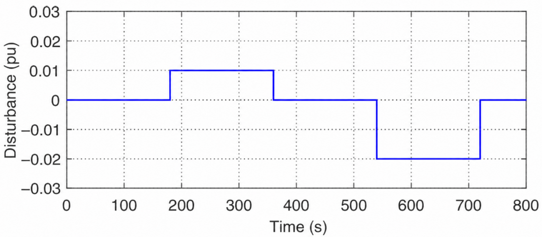
The step-change disturbance case can be regarded as a simplified representation of sudden load increase or load shedding events in the interconnected grid, which are commonly used to evaluate the transient frequency support capability of renewable power plants. In this subsection, simulations are carried out to evaluate the performance of the proposed plant-level coordinated frequency support strategy under a step-change load disturbance. The disturbance profile is shown in Figure 3, and the corresponding dynamic responses are presented in Figure 4, Figure 5, Figure 6 and Figure 7. This test is intended to assess the transient frequency support capability, plant-level active power coordination performance, and HESS energy-state behavior of the proposed strategy under an abrupt active power imbalance.
Figure 3.
Applied step-change load disturbance profile.
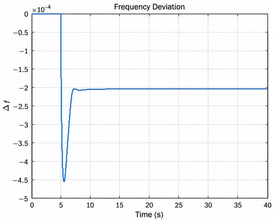
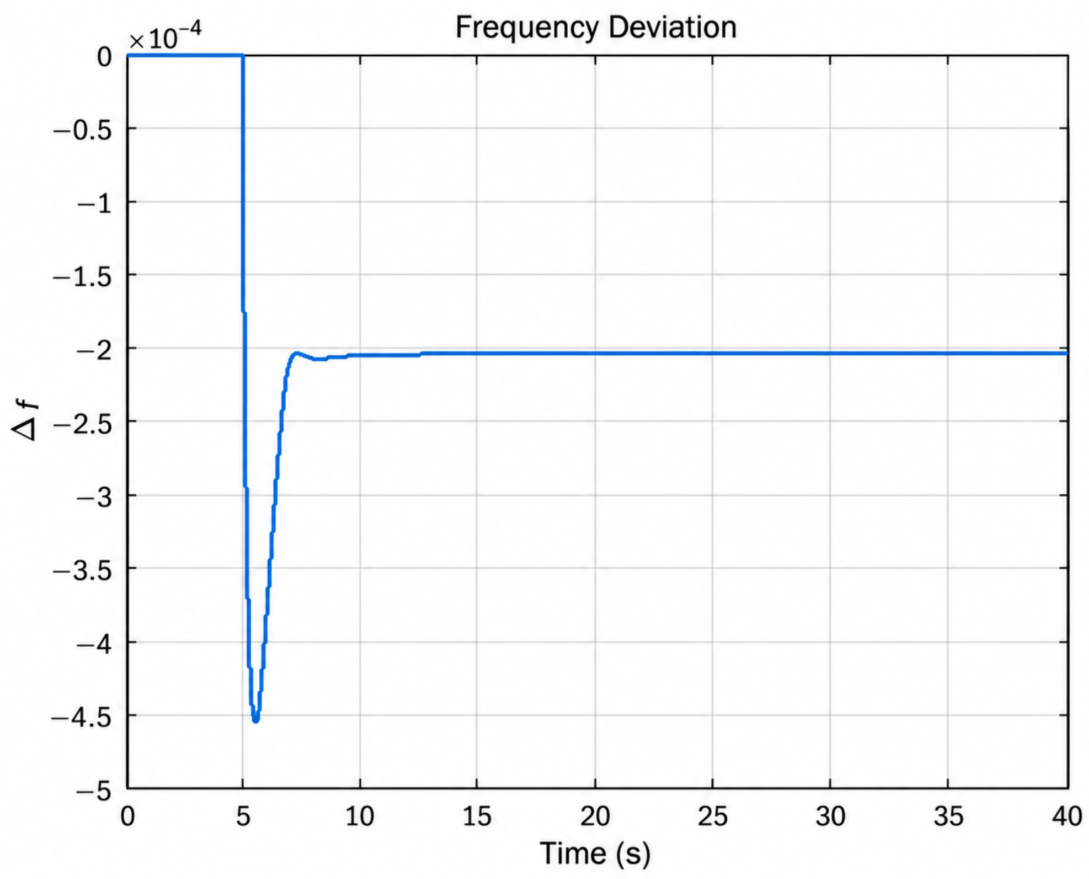
Figure 4.
Frequency deviation under proposed strategy.
Figure 5.
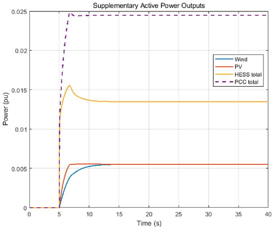
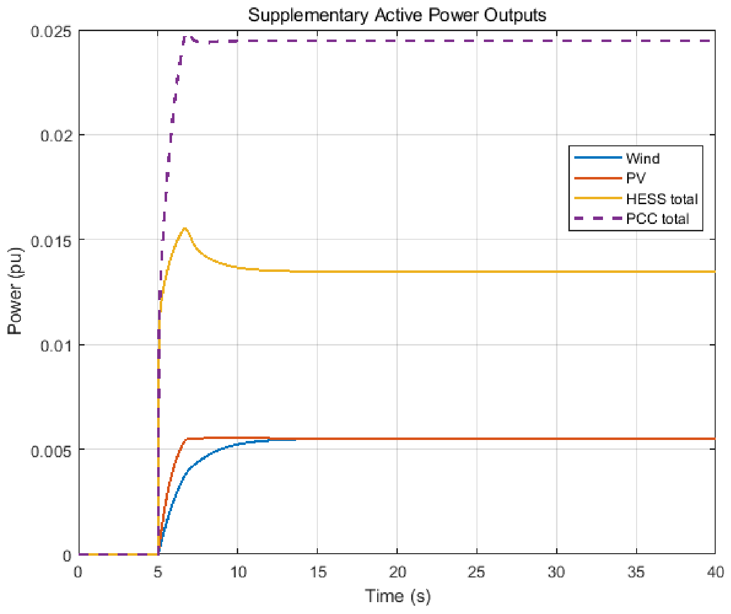
Supplementary active power outputs of wind, PV, and HESS.
Figure 6.
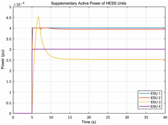
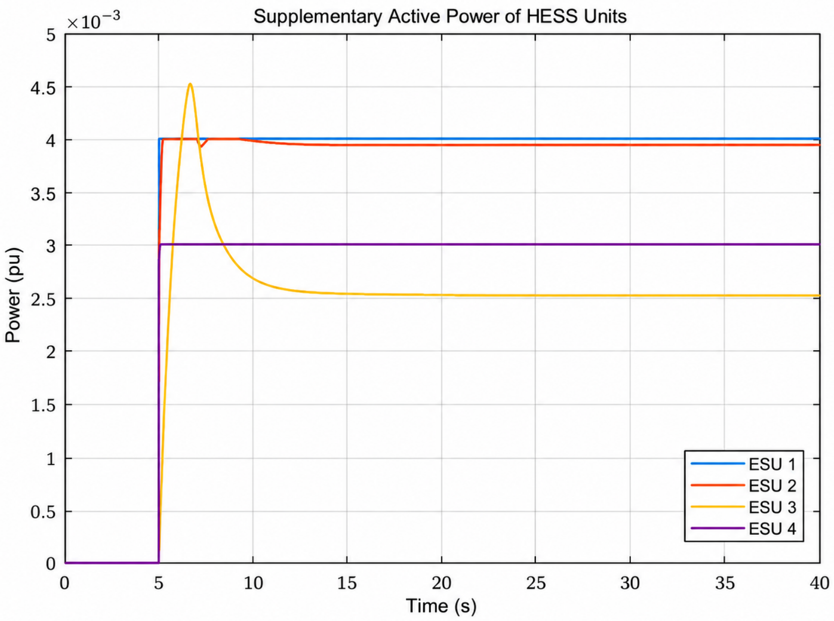
Power responses of heterogeneous HESS units.
Figure 7.
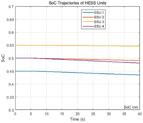
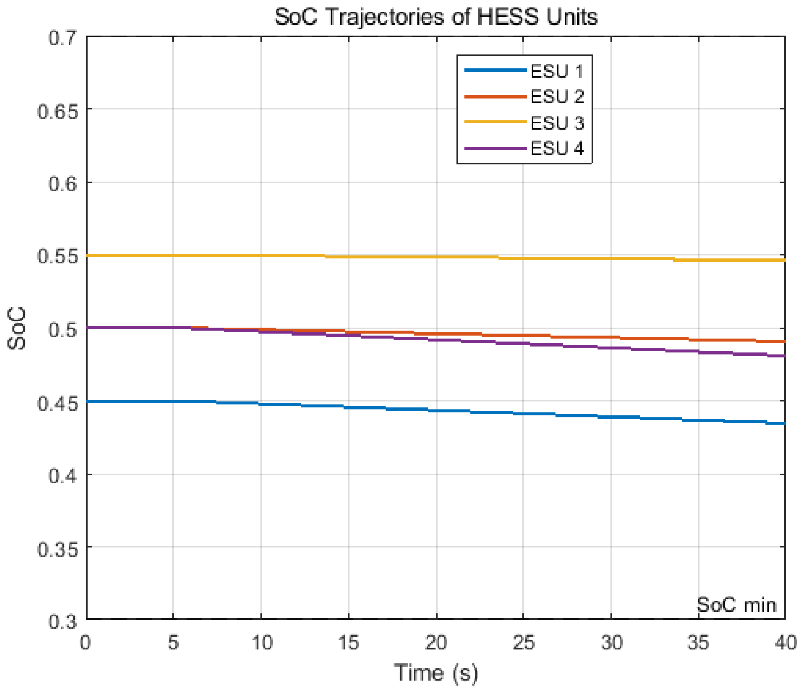
SoC trajectories of HESS units.
Figure 3 shows the complete disturbance sequence over the full simulation horizon, while Figure 4, Figure 5, Figure 6 and Figure 7 present a time-shifted local transient window around a representative disturbance event for clearer visualization of the short-term dynamic responses.
As shown in Figure 4, the system frequency deviation is effectively suppressed after the disturbance and converges rapidly to a new operating region with a relatively small transient excursion. As shown in Figure 4, the proposed coordinated strategy effectively suppresses the transient frequency deviation and rapidly restores the system to the post-disturbance operating region. The frequency nadir is approximately p.u. and the response enters the post-disturbance quasi-steady region at approximately s, corresponding to a settling process of about 3 s measured from the disturbance onset at s. These results demonstrate that the coordinated contribution of renewable generation and HESS can improve the dynamic frequency response of the renewable power plant under sudden load variations.
The supplementary active power responses in Figure 5 further show that the wind subsystem, the PV subsystem, and the HESS are coordinately mobilized following the disturbance. In the initial stage, the HESS provides the dominant fast support because of its superior response speed, whereas the wind and PV subsystems gradually increase their supplementary outputs and provide sustained support during the subsequent recovery stage. As a result, the total support power at the PCC rises rapidly after the disturbance and then converges to a stable level. This coordinated response indicates that the proposed strategy can effectively exploit the complementary dynamic characteristics of renewable generation and storage resources at the plant level.
Figure 6 shows the detailed power responses of individual HESS units. It can be observed that the storage units exhibit differentiated dynamic behaviors consistent with their heterogeneous characteristics. Fast-response units participate more promptly in the initial transient support process, whereas units with relatively larger energy capacities contribute more sustained support during the later stage. This result confirms that the proposed strategy does not rely on rigid uniform allocation, but instead distributes the support effort according to unit-level response capability and operational characteristics. Such a coordination pattern is beneficial for both short-term support effectiveness and the long-term dispatchability of heterogeneous storage resources.
In addition, Figure 7 shows that the SoC trajectories of all heterogeneous storage units remain within the prescribed operating limits throughout the entire support process. Although different units exhibit different rates of energy depletion due to their distinct dynamic properties, power limits, and allocation weights, no unit reaches or violates the predefined SoC safety bounds. This indicates that the proposed strategy can deliver effective transient frequency support without causing excessive local overuse of any individual storage unit. Therefore, the step-disturbance results verify that the proposed method can simultaneously achieve satisfactory transient frequency support, effective plant-level active power coordination, and acceptable HESS energy management. Although the SoC trajectories are not forced to converge to an identical value, their evolution remains bounded without excessive divergence, which is consistent with the intended SoC imbalance-mitigation objective.
4.2.2. Results Under Random Load Disturbances
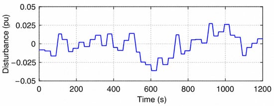
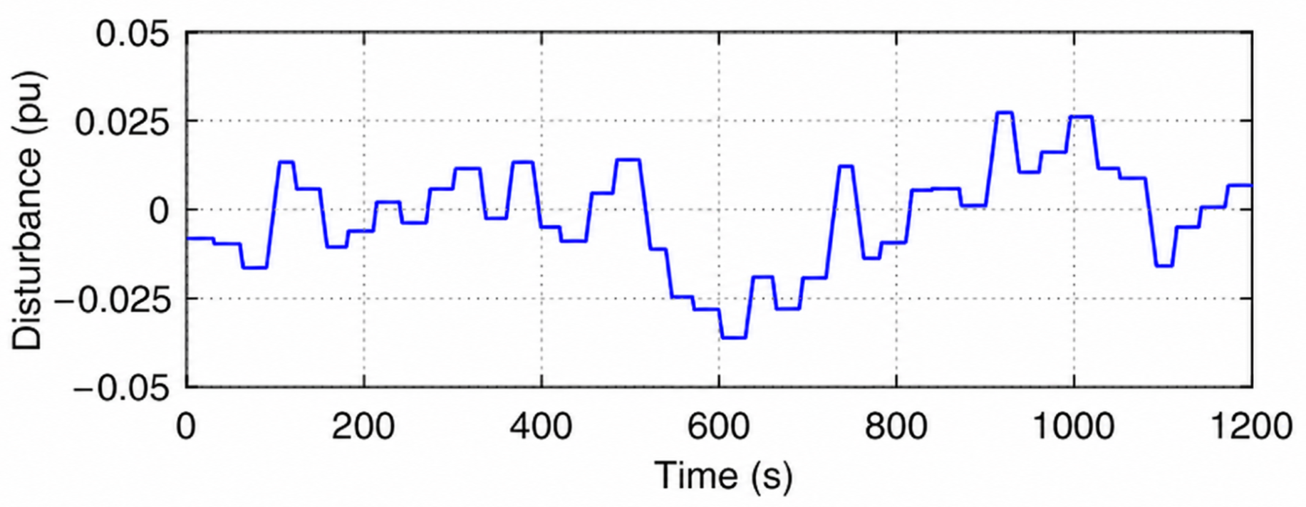
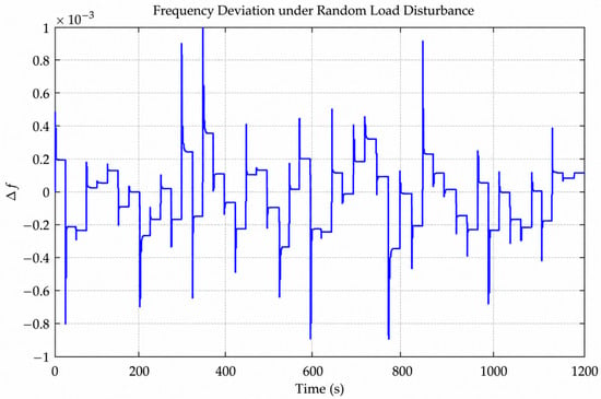
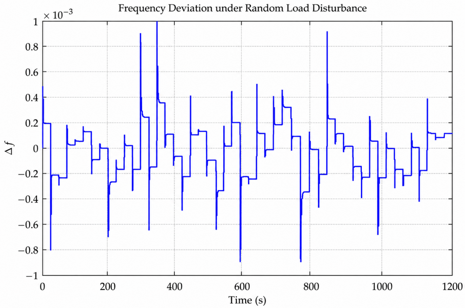
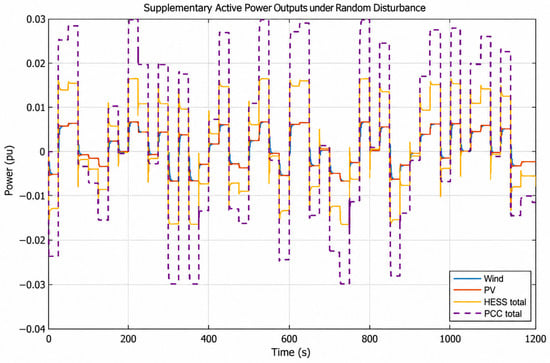
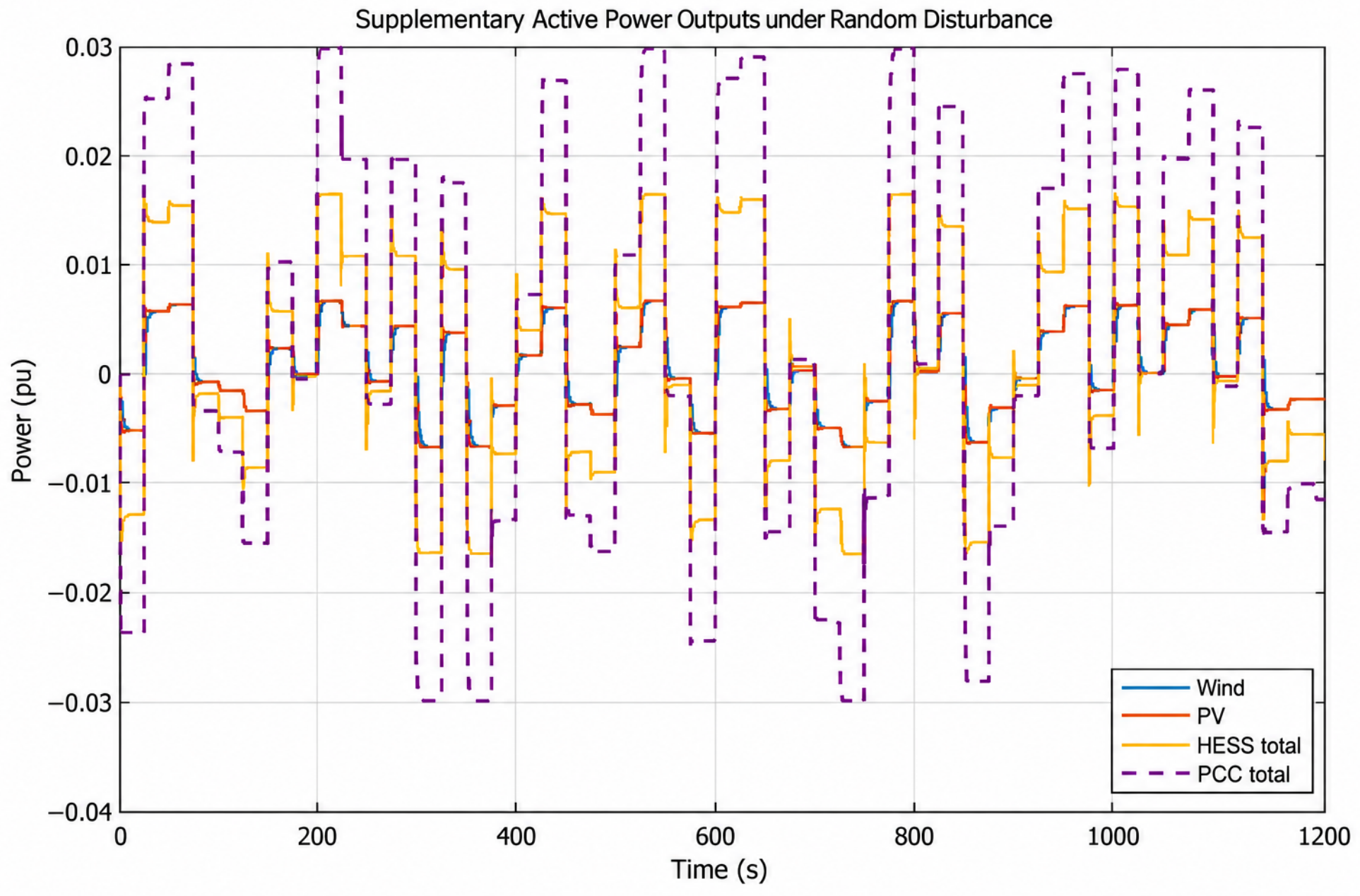
The random disturbance case is introduced to emulate continuous net-load fluctuation in practical power system operation and to assess the robustness of the proposed coordinated control strategy under stochastic operating conditions. In this subsection, simulations are conducted to further evaluate the performance of the proposed coordinated frequency support strategy under random load disturbances. The disturbance profile is shown in Figure 8, and the corresponding results are presented in Figure 9, Figure 10, Figure 11 and Figure 12. Compared with the step-disturbance case, this scenario is more suitable for assessing the continuous regulation capability, disturbance rejection performance, and energy management behavior of the proposed method under stochastic operating conditions.
Figure 8.
Applied random load disturbance profile.
Figure 9.
Frequency deviation under random load disturbance.
Figure 10.
Supplementary active power outputs under random disturbance.
Figure 11.
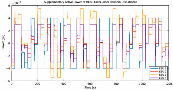
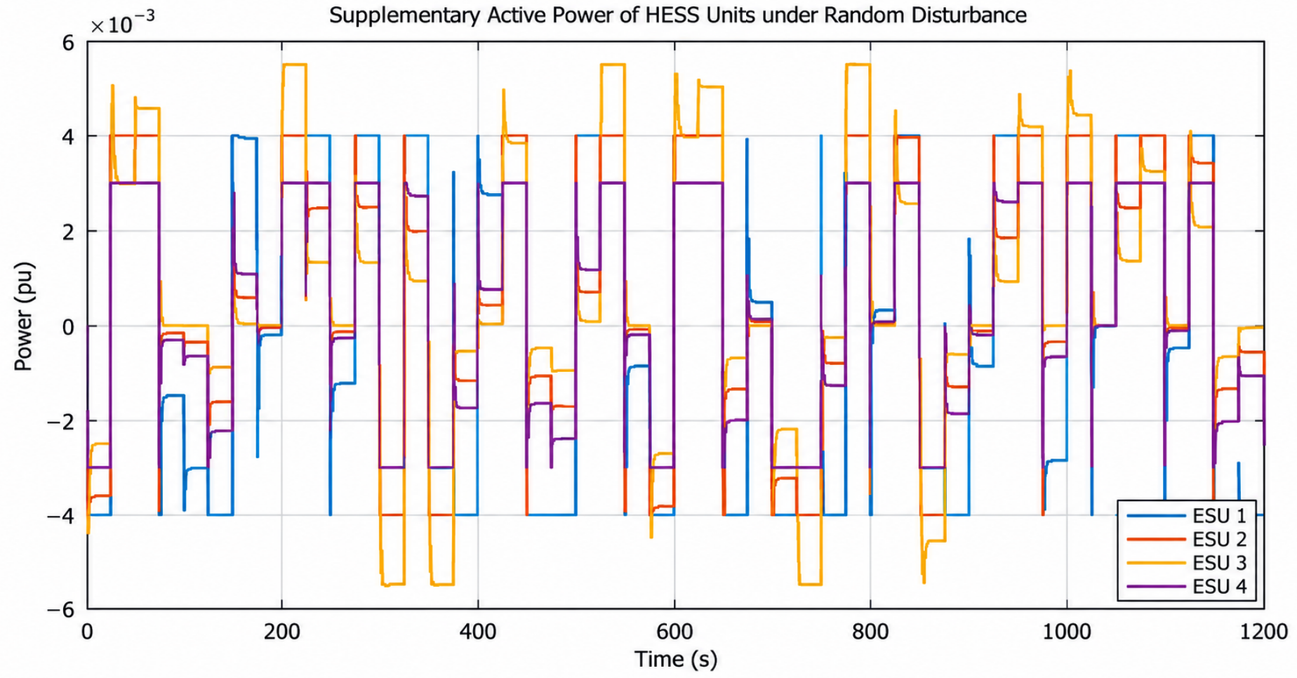
Supplementary active power of HESS units under random disturbance.
Figure 12.
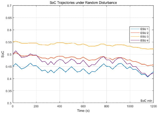
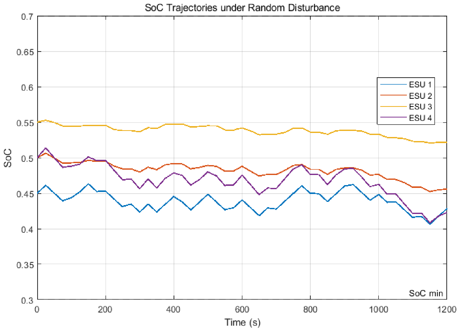
SoC trajectories under random disturbance.
Figure 9 shows that the system frequency deviation remains within a relatively narrow range throughout the simulation horizon, despite the continuous variation in the load disturbance. Although persistent fluctuations are present because of the stochastic nature of the disturbance, no obvious divergence or excessive amplification can be observed. This result indicates that the proposed strategy can provide effective plant-level frequency support and maintain satisfactory robustness under time-varying operating conditions. It also demonstrates that the coordinated contribution of renewable generation and heterogeneous HESS can mitigate the influence of random active power imbalance on system frequency.
The supplementary active power responses shown in Figure 10 further illustrate the coordinated support mechanism of the proposed strategy. Following the variation in the disturbance demand, the wind subsystem, PV subsystem, and HESS jointly participate in plant-level frequency support at the PCC. Among them, the HESS provides the major fast-varying support component owing to its superior dynamic response capability, whereas the wind and PV subsystems contribute smoother and more sustained supplementary power within their available reserve margins. Consequently, the total support power at the PCC can track the disturbance variation in a coordinated manner, which reflects the complementary roles of renewable generation and storage resources in the proposed framework.
The detailed responses of individual HESS units, as shown in Figure 11, clearly reveal the heterogeneous characteristics of the storage subsystem. Different units exhibit different response magnitudes and dynamic patterns during the support process, indicating that the proposed controller allocates support effort according to unit-level dynamic properties and energy-state conditions rather than through rigid uniform dispatch. Fast-response storage units undertake more frequent and rapid power regulation, whereas other units provide relatively smoother support over longer time intervals. This result confirms that the proposed strategy can effectively exploit HESS heterogeneity and improve the flexibility of plant-level support allocation.
Figure 12 presents the SoC trajectories of the heterogeneous storage units under random load disturbances. It can be seen that all SoC trajectories remain within the prescribed operating limits during the entire simulation period, which verifies the effectiveness of the proposed strategy in maintaining storage operational safety. Meanwhile, the SoC evolution of different units exhibits differentiated but well-regulated behavior, reflecting the fact that the power allocation process is jointly influenced by response capability and available energy margin. Although the storage units experience different levels of energy depletion due to their distinct dynamic roles, no unit approaches the safety boundary excessively or exhibits abnormal SoC drift. This demonstrates that the proposed strategy can provide continuous frequency support without sacrificing acceptable HESS energy management performance. The results therefore indicate effective SoC-aware coordination rather than strict SoC equalization among the heterogeneous storage units.
Overall, the results under random load disturbances verify that the proposed coordinated strategy possesses satisfactory continuous regulation capability, robust disturbance rejection performance, and effective plant-level resource coordination. By jointly coordinating wind power, PV generation, and heterogeneous HESS units, the proposed method can suppress frequency fluctuations, allocate support power according to resource characteristics, and maintain acceptable SoC behavior under stochastic operating conditions.
5. Conclusions
This paper proposed a plant-level coordinated frequency support strategy for renewable power plants integrating wind power, photovoltaic generation, and heterogeneous hybrid energy storage systems. An equivalent grid frequency response model and aggregated dynamic models of wind, PV, and HESS were incorporated into a unified control-oriented framework, in which renewable reserve limits, power constraints, response dynamics, and SoC evolution were explicitly considered. On this basis, the coordinated frequency support problem was formulated as a constrained multi-resource active power allocation problem.
Based on the unified model, the proposed MPC strategy dynamically allocates supplementary active power among wind, PV, and heterogeneous HESS units according to their response characteristics, reserve availability, and energy states. The HESS mainly provides rapid support during the initial transient stage, whereas wind and PV contribute relatively sustained supplementary power within their available reserve margins. This coordination enables different resources to complement each other in both response speed and sustained support capability.
Simulation studies under step-change and random load disturbances verified the dynamic performance of the proposed strategy. Under the representative step disturbance occurring at approximately s, the frequency deviation reaches a minimum of approximately p.u. and enters the post-disturbance quasi-steady region at approximately s, corresponding to a settling process of about 3 s from the disturbance onset. Under random load disturbances, the frequency deviation remains approximately within p.u., demonstrating stable continuous regulation under time-varying operating conditions. The corresponding power responses further show that wind, PV, and HESS can be coordinately mobilized according to their respective dynamic characteristics.
The HESS results further show that all heterogeneous storage units remain within the prescribed SoC range of – p.u. throughout the support process. Although the storage units exhibit different energy depletion characteristics due to their distinct response speeds, power limits, and allocation patterns, no unit violates its SoC safety boundary. These results indicate that the proposed strategy can improve plant-level frequency support while maintaining coordinated active power allocation and acceptable energy-state management of heterogeneous HESS units.
Future work will focus on incorporating more detailed converter-level dynamics and communication delay effects, extending the proposed strategy to multi-plant or multi-area renewable power systems, and conducting hardware-in-the-loop or real-time simulation experiments to further evaluate its practical implementation feasibility.
Author Contributions
Conceptualization, T.J.; methodology, Z.G.; software, T.J.; validation, T.J., H.T. and C.S.; formal analysis, W.C.; investigation, W.C.; resources, Z.G.; data curation, Z.G.; writing—original draft preparation, T.J.; writing—review and editing, Z.G.; visualization, W.C.; supervision, C.S.; project administration, H.T.; funding acquisition, W.C. All authors have read and agreed to the published version of the manuscript.
Funding
This research was funded by the National Key Research and Development Program of China under the project “Remote Monitoring and Fault Diagnosis Technology for Offshore Wind Power Grid-Connected Systems” (Grant No. 2023YFB2406900).
Data Availability Statement
The original contributions presented in this study are included in the article. Due to project confidentiality restrictions, specific MPC tuning parameters and implementation files are not publicly available.
Conflicts of Interest
Tianbin Jiang, Zhongming Gong, and Wenbo Cao were employed by Xinjiang Lvfa Electric Power Energy Co., Ltd. Haining Tang was employed by the State Grid Electric Power Research Institute, NARI Nanjing Control System Co., Ltd. The remaining author declares that the research was conducted in the absence of any commercial or financial relationships that could be construed as potential conflicts of interest.
References
- Yan, K.; Li, G.; Zhang, R.; Xu, Y.; Jiang, T.; Li, X. Frequency Control and Optimal Operation of Low-Inertia Power Systems with HVDC and Renewable Energy: A Review. IEEE Trans. Power Syst. 2024, 39, 4279–4295. [Google Scholar] [CrossRef] [Scilit]
- Yang, X.-Y.; Liu, Y.-X.; Xing, G.-T. Analysis of wind farm participation in the frequency regulation market considering wind power uncertainty. Int. J. Electr. Power Energy Syst. 2021, 130, 106946. [Google Scholar] [CrossRef] [Scilit]
- Gao, R.; Hui, S.; Gao, B.; Liu, X. Bi-Level Game-Theoretic Bidding Strategy for Large-Scale Renewable Energy Generators Participating in the Energy–Frequency Regulation Market. Energies 2025, 18, 2604. [Google Scholar] [CrossRef] [Scilit]
- Atawi, I.E.; Al-Shetwi, A.Q.; Magableh, A.M.; Albalawi, O.H. Recent advances in hybrid energy storage system integrated renewable power generation: Configuration, control, applications, and future directions. Batteries 2023, 9, 29. [Google Scholar] [CrossRef] [Scilit]
- Chen, T.; Ren, J.; Liu, Y.; Xu, Y.; Zhao, M.; Yuan, J. A Coordinated Inertia Support Strategy for Wind–PV–Thermal Storage Systems Considering System Inertia Demand. Energies 2025, 18, 6468. [Google Scholar] [CrossRef] [Scilit]
- Zhou, D.; Zou, Z.; Dan, Y.; Wang, C.; Teng, C.; Zhu, Y. An integrated strategy for hybrid energy storage systems to stabilize the frequency of the power grid through primary frequency regulation. Energies 2025, 18, 246. [Google Scholar] [CrossRef] [Scilit]
- Tian, X.; Chi, Y.; Cheng, P.; Zhao, Y.; Liu, H. Optimal frequency response coordinated control strategy for hybrid wind-storage power plant based on state reconstruction. IET Renew. Power Gener. 2024, 18, 2892–2906. [Google Scholar] [CrossRef] [Scilit]
- González-Inostroza, P.; Rahmann, C.; Álvarez, R.; Haas, J.; Nowak, W.; Rehtanz, C. The role of fast frequency response of energy storage systems and renewables for ensuring frequency stability in future low-inertia power systems. Sustainability 2021, 13, 5656. [Google Scholar] [CrossRef] [Scilit]
- Lu, W.; Tan, E.; Cheng, L.; Zhang, K.; Liu, W. Optimizing Energy Storage Participation in Primary Frequency Regulation: A Novel Analytical Approach for Virtual Inertia and Damping Control in Low-Carbon Power Systems. Processes 2025, 13, 1146. [Google Scholar] [CrossRef] [Scilit]
- Zhang, H.; Zhang, X.; Wang, Z.; He, G.; Cui, K.; Wang, X. Capacity configuration of hybrid energy storage power stations participating in power grid frequency modulation. Processes 2023, 11, 2843. [Google Scholar] [CrossRef] [Scilit]
- Zhu, F.; Zhou, X.; Zhang, Y.; Xu, D.; Fu, J. A load frequency control strategy based on disturbance reconstruction for multi-area interconnected power system with hybrid energy storage system. Energy Rep. 2021, 7, 8849–8857. [Google Scholar] [CrossRef] [Scilit]
- Akram, U.; Shah, R.; Mithulananthan, N. Hybrid energy storage system for frequency regulation in microgrids with source and load uncertainties. IET Gener. Transm. Distrib. 2019, 13, 5048–5057. [Google Scholar] [CrossRef] [Scilit]
- Meng, G.; Lu, Y.; Liu, H.; Ye, Y.; Sun, Y.; Tan, W. Adaptive droop coefficient and SOC equalization-based primary frequency modulation control strategy of energy storage. Electronics 2021, 10, 2645. [Google Scholar] [CrossRef] [Scilit]
- Zhao, T.; Parisio, A.; Milanović, J.V. Distributed control of battery energy storage systems for improved frequency regulation. IEEE Trans. Power Syst. 2020, 35, 3729–3738. [Google Scholar] [CrossRef] [Scilit]
- Tobar-Rosero, O.A.; Candelo-Becerra, J.E.; Montano, J.; Quintero-Henao, L.F.; Hoyos, F.E. Battery Energy Storage Systems for Primary Frequency Regulation Applied to a Thermal Generation Plant. Electricity 2026, 7, 22. [Google Scholar] [CrossRef] [Scilit]
- Wang, L.; Wang, J.; Wang, Y.; Lin, F.; Zhu, X.; Jiang, C.; Shi, R. Capacity Optimization Configuration of a Highway Ring Multi-Microgrid System Considering the Coordination of Fixed and Mobile Energy. Sustainability 2026, 18, 629. [Google Scholar] [CrossRef] [Scilit]
- Elkhidir, L.; Khan, K.; Al-Muhaini, M.; Khalid, M. Enhancing transient response and voltage stability of renewable integrated microgrids. Sustainability 2022, 14, 3710. [Google Scholar] [CrossRef] [Scilit]
- Ma, C.T.; Hsieh, C.L. Investigation on hybrid energy storage systems and their application in green energy systems. Electronics 2020, 9, 1907. [Google Scholar] [CrossRef] [Scilit]
- Zhang, T.; Zhang, Y.; Wang, Z.; Yao, Z.; Zhang, Z. Voltage Fluctuation Enhancement of Grid-Connected Power System Using PV and Battery-Based Dynamic Voltage Restorer. Electronics 2025, 14, 3413. [Google Scholar] [CrossRef] [Scilit]
- Sun, F.; Li, Q.; Wang, W. Frequency regulation reserve allocation for integrated hydropower plant and energy storage systems via the marginal substitution. Electronics 2025, 14, 1582. [Google Scholar] [CrossRef] [Scilit]
- Wang, L.; Zhang, R.; Zang, Q.; Cheng, Z.; Su, C.; Li, Z.; Zhang, H. Study on photovoltaic primary frequency control strategy at different time scales. IET Renew. Power Gener. 2024, 18, 3994–4003. [Google Scholar] [CrossRef] [Scilit]
- Al Kez, D.; Foley, A.M.; Ahmed, F.; Morrow, D.J. Overview of frequency control techniques in power systems with high inverter-based resources: Challenges and mitigation measures. IET Smart Grid 2023, 6, 447–469. [Google Scholar] [CrossRef] [Scilit]
- Meng, J.; Sun, Y.; Wang, Y.; Zhao, P.; Liu, B.; Wang, K. Cooperative adaptive inertial control for PV and energy storage units with multiple constraints. IET Renew. Power Gener. 2022, 16, 2076–2087. [Google Scholar] [CrossRef] [Scilit]
- Soloperto, R.; Köhler, J.; Allgöwer, F. A nonlinear MPC scheme for output tracking without terminal ingredients. IEEE Trans. Autom. Control 2022, 68, 2368–2375. [Google Scholar] [CrossRef] [Scilit]

Disclaimer/Publisher’s Note: The statements, opinions and data contained in all publications are solely those of the individual author(s) and contributor(s) and not of MDPI and/or the editor(s). MDPI and/or the editor(s) disclaim responsibility for any injury to people or property resulting from any ideas, methods, instructions or products referred to in the content. |
© 2026 by the authors. Licensee MDPI, Basel, Switzerland. This article is an open access article distributed under the terms and conditions of the Creative Commons Attribution (CC BY) license.