


Abstract
The free-piston Stirling generator (FPSG) is a thermo-mechanical–electrical energy conversion system in which the linear alternator converts reciprocating mechanical power into electrical power. Reliable system-level power calculations require an electromechanical conversion coefficient that represents the alternator under the relevant operating condition. This study evaluates a circuit-resonance-based procedure for identifying the operating inductance and electromotive force (EMF) constant from measured voltage and current amplitudes and phases. Static and dynamic tests were conducted on one laboratory-scale alternator driven by opposed compressors. The dynamically identified EMF constant was compared with the equilibrium-position and stroke-equivalent static force constants in the same Sage model. At 60 Hz with a 4 Ω load and a 272 μF series capacitor, the run using the dynamic parameter gave a mean absolute error of 159.07 W, a root mean square error of 231.72 W, and a mean absolute percentage error of 2.60% over 1876 experimental points; the corresponding mean absolute percentage errors for the two static inputs were 45.94% and 43.67%. These results quantify agreement for the tested alternator and operating condition. Further measurements at other frequencies, loads, and machines are needed to establish broader applicability.
1. Introduction
With the continuous growth of the global population and the steady improvement in living standards, energy demand has continued to increase. However, the excessive use of traditional fossil fuels has led to severe environmental pollution, thereby accelerating the transition toward sustainable clean energy technologies. Among various energy conversion technologies, free-piston Stirling generators, characterized by wide adaptability to diverse heat sources, high reliability, long service life, and low noise operation, have become a highly promising solution for future clean energy systems. In Stirling generators, the linear alternator serves as the core component for electromechanical energy conversion, and its performance directly affects the overall efficiency of the generator. With the growing demand for high-efficiency and high-power generation, performance optimization of linear alternators has become an increasingly important research topic.
Linear-alternator design and performance evaluation in free-piston Stirling generators generally require coupled consideration of the thermodynamic, mechanical, and electromagnetic subsystems. System-level simulation tools such as Sage are commonly used to describe the thermodynamic and dynamic behavior of the Stirling system, while electromagnetic analysis tools are used to evaluate the characteristics of the linear alternator. However, the accuracy of system-level performance prediction depends strongly on the electromechanical parameters introduced into the model. Parameters obtained under static or quasi-static conditions may not fully represent the electromagnetic behavior of the alternator during high-frequency reciprocating operation.
Early studies by the National Aeronautics and Space Administration (NASA) investigated the operating characteristics and electromechanical behavior of free-piston Stirling engines and their linear alternators [1,2], while a later review summarized the broader development of free-piston Stirling engines [3]. Subsequent studies developed experimental platforms for investigating interactions among the engine, linear alternator, control system, and electrical load [4,5,6,7], and various methods have been used to measure or identify displacement, force, induced EMF, current, and output power for linear machines and free-piston Stirling systems [8,9,10,11,12,13,14,15,16].
More recent studies have increasingly focused on coupled system modeling, dynamic response, and performance optimization. Jia et al. established a coupled simulation model of a free-piston Stirling generator and investigated the interaction between the Stirling engine and linear alternator [17]. Xiao et al. investigated the dynamic response of a dual-opposed free-piston Stirling generator [18], while Jia et al. combined theoretical and experimental analyses to evaluate generator performance under high cold-end-temperature conditions [19]. Kim and Sim examined the dynamic behavior and operable range of free-piston Stirling engines with respect to charge pressure and operating frequency [20]. In parallel with these modeling and experimental efforts, optimization methods have also been introduced to improve system performance. Chen et al. applied a self-directed online machine-learning approach to performance optimization [21], Cheng and Lin employed a variable-step simplified conjugate-gradient method for computational optimization [22], and Chen et al. used response-surface methodology to optimize a free-piston Stirling engine with multi-section regenerators [23].
These studies have substantially advanced system-level dynamic modeling, experimental characterization, and performance optimization. However, they primarily address the behavior or optimization of the overall free-piston Stirling system and do not resolve the specific question considered here: how an electromechanical parameter identified during actual oscillatory operation should be determined and whether it provides a more representative input for system-level power prediction than a conventionally measured static force constant. Dynamic testing itself is therefore not the novelty of the present study. Instead, this work develops a circuit-resonance-based procedure in which the dynamic inductance and EMF constant of the linear alternator are identified from the measured voltage and current amplitudes and their phase relationship during oscillatory operation.
Accordingly, this study first measures the position dependence of the static force constant, then identifies the dynamic inductance and EMF constant using the proposed circuit-resonance procedure, and finally introduces the identified parameters into the same Sage model for comparison with experimental electrical-power data. Predictions based on the dynamically identified EMF constant are compared with those obtained using both the equilibrium-position static force constant and a stroke-equivalent static force constant. This approach enables the influence of the parameter-identification method to be evaluated under the investigated operating condition while avoiding the assumption that the identified dynamic parameter is universally applicable to other frequencies, loads, or alternators.
2. Testing Methods
In order to accurately characterize the electromagnetic properties of a linear alternator and to evaluate the suitability of electromagnetic parameters obtained using different test methods for predicting the alternator’s performance, static and dynamic tests were conducted. The static test measured the force constant as a function of piston displacement. The dynamic test used terminal-voltage and current measurements during oscillatory operation to identify the dynamic inductance and EMF constant.
2.1. Static Testing
The principle of the static test is illustrated by Equations (1) and (2), and the piston force analysis is shown in Figure 1. At each prescribed displacement from the equilibrium position, the piston was held stationary. The electromagnetic force was determined from the force difference before and after direct current (DC) was applied. Force, current, and displacement were recorded at a sampling frequency of 2000 Hz, with each condition measured twice. The measured force and current were then used to calculate the static force constant as a function of piston position.
Figure 1.
Force analysis diagram of the piston.
The static test platform consisted of a custom-built push–pull device, a force gauge, a laser displacement sensor, a portable power supply, a pneumatic system, and a data acquisition system. The push–pull device positioned and held the piston during measurements. The pneumatic system provided air cushioning to reduce the influence of mechanical friction, and the power supply provided the excitation current. The data acquisition system recorded force, current, and piston displacement.
The electromagnetic force was measured using an FSRT-500kg push–pull force gauge (Forsentek Co., Limited, Shenzhen, China) (Forsentek: accuracy class: 0.02%). Current was measured using a Tektronix A621 current probe (Tektronix, Inc., Beaverton, OR, USA) (sensitivity: 10 mV/A; peak-current capacity: 200 A; reading accuracy: ±2%; frequency response: 0–50 kHz). Piston displacement relative to the equilibrium position was measured using a KEYENCE LK-G80 laser displacement sensor (KEYENCE Corporation, Osaka, Japan). In diffuse-reflection mode, the sensor has a reference distance of 80 mm, a measurement range of ±15 mm, a linearity of ±0.05% of full scale, and a repeatability of 0.2 μm.
The measurement uncertainty was evaluated according to the propagation of uncertainty. The uncertainty reported for the static force constant is an expanded uncertainty calculated with a coverage factor of k = 2, corresponding to an approximate 95% level of coverage under the stated assumptions. The accuracy specifications provided by the instrument manufacturers were treated as uncertainty limits with a rectangular probability distribution. The force gauge has an accuracy class of 0.02% of full scale. Accordingly, its manufacturer-specified force error limit was taken as , where is the full-scale force. The corresponding standard uncertainty was obtained by dividing this limit by , assuming a rectangular distribution. The current probe has a reading accuracy of ±2%; its standard uncertainty was therefore estimated as times the measured current. The combined standard uncertainty of the static force constant, calculated as the force-to-current ratio, was obtained by propagating the force and current uncertainties, assuming independent measurements. Expanded uncertainties were calculated using a coverage factor of k = 2. Each static measurement condition was repeated twice, and the two measurements were used to assess measurement repeatability.
2.2. Dynamic Testing
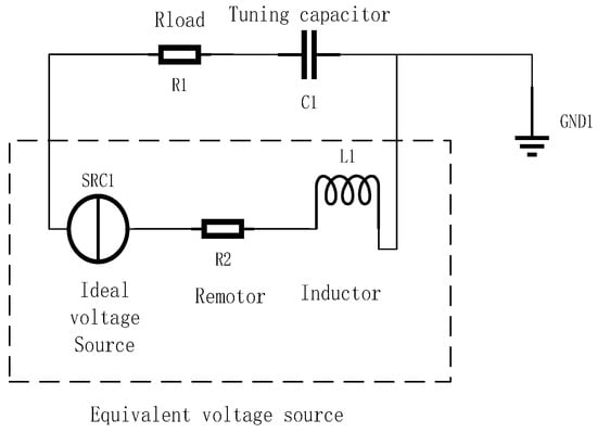
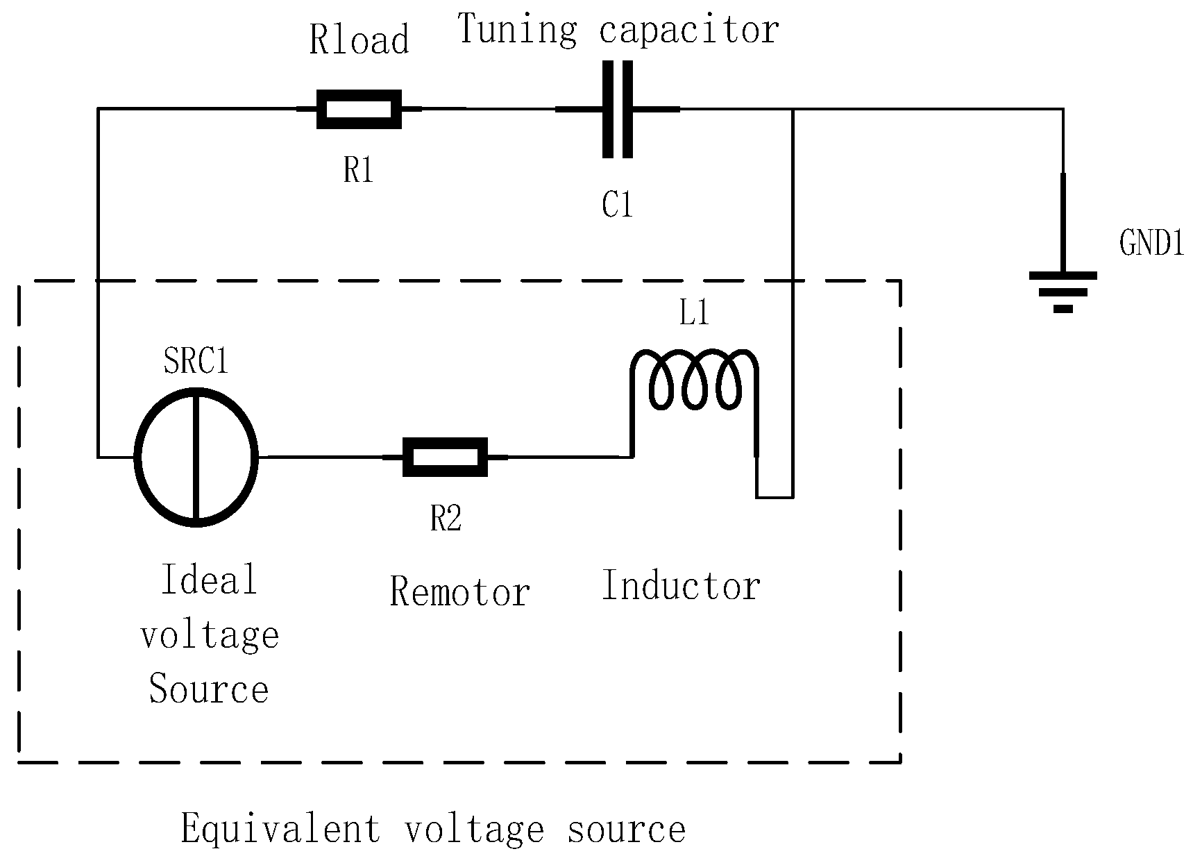
The dynamic test is based on Kirchhoff’s voltage law and is used to identify two operating-condition-dependent electromagnetic parameters of the linear alternator: the dynamic inductance and the EMF constant. The corresponding equivalent circuit is illustrated in Figure 2. In this model, the alternator is represented as an equivalent voltage source composed of an ideal voltage source, coil inductance, and internal resistance. An external resistor is employed to simulate load power consumption, while a tuning capacitor is introduced to compensate for the coil inductance, enabling the circuit to operate under resonant conditions.
Figure 2.
Equivalent circuit diagram.
The testing principle is described by Equations (3)–(6).
Within the internal circuit, part of the induced electromotive force generated in the coil is dropped across the coil inductance and internal resistance.
For the parameter-identification procedure, the internal-resistance term is neglected when deriving the simplified circuit equation below.
All oscillatory variables are expressed as cosine functions with piston displacement as the phase reference; piston velocity leads displacement by 90°.
When and , the piston reaches its maximum displacement while the velocity of the piston mover becomes zero. By substituting the experimentally measured amplitudes and phase angles of voltage and current into Equation (5), the dynamic inductance is determined. This inductance is then used in Equation (6) to determine the dynamic EMF constant.
When and , the piston is located at the equilibrium position, and the velocity of the piston reaches its maximum value. Substituting the measured voltage and current amplitudes and phase angles, together with the calculated dynamic inductance, into Equation (6), the electromotive force constant is determined. Multiplication by j represents a 90° phase advance under the adopted phasor convention. Taking the real component of the inductive-voltage phasor therefore changes the cosine argument from φI − π/2 to φI. This phase shift is incorporated into Equation (6), yielding an explicitly real-valued expression for BL.
During the dynamic tests, the alternator terminal voltage and current were measured simultaneously using a Tektronix P5200A high-voltage differential probe (Tektronix, Inc., Beaverton, OR, USA) and a Tektronix A621 current probe (Tektronix, Inc., Beaverton, OR, USA), respectively. The P5200A was operated at an attenuation ratio of 500×, with a differential measurement range of ±1300 V (peak) and a reading accuracy of ±2%. The A621 current probe has an output sensitivity of 10 mV/A, a peak-current capacity of 200 A, a reading accuracy of ±2%, and a frequency-response range of 0–50 kHz. Both signals were acquired simultaneously at a sampling frequency of 2000 Hz using the same acquisition time base.
The fundamental voltage and current amplitudes and their corresponding phase angles were determined by fast Fourier transform (FFT) analysis implemented in NI LabVIEW (version 2024 Q1). Because the voltage and current signals were acquired synchronously, their phase difference was calculated directly from the fundamental components referenced to the same time base. These measured amplitudes and phase angles were subsequently used in Equations (5) and (6) to identify the dynamic inductance and EMF constant. Dynamic piston motion was measured using a PCB Piezotronics 353B16 accelerometer, with the acceleration calculated from the sensor output using the nominal sensitivity of 10 mV/g. The fundamental velocity amplitude was obtained as V = a/(2πf), where a is the fundamental acceleration amplitude and f is the operating frequency. The laser displacement sensor was used only for static characterization.
The uncertainty contributions associated with voltage and current amplitudes were estimated from the manufacturer-specified ±2% reading accuracies of the two probes. These accuracy limits were treated as rectangular distributions, giving a standard relative uncertainty of 0.02/√3 for each amplitude measurement. Because Equations (5) and (6) also depend explicitly on measured phase angles, phase repeatability was evaluated separately using 14 repeated records at the same representative operating condition. After unwrapping the phase angles onto common 360° branches, the sample standard deviations were 0.01499° for voltage phase, 0.01490° for current phase, and 0.01206° for their phase difference. These standard deviations were calculated using n − 1 in the denominator, where n = 14. They characterize the Type-A phase-repeatability contribution and were not included in the simplified amplitude-based propagated uncertainty budget.
A simplified amplitude-based uncertainty budget was evaluated by neglecting frequency and phase uncertainties. The reported ±2% voltage and current reading limits were treated as rectangular distributions, giving relative standard uncertainties of 1.1547% for both electrical amplitudes. Because the nominal accelerometer sensitivity of 10 mV/g was used, its ±10% sensitivity tolerance was also treated as a rectangular distribution, giving a relative standard uncertainty contribution of 5.7735% to the acceleration amplitude. With frequency uncertainty neglected, the same relative contribution applies to the velocity amplitude.
For the resistance-neglecting identification equations, propagation of these independent amplitude contributions gave relative standard uncertainties of 1.6330% for the dynamic inductance and 5.8878% for the EMF constant. With a coverage factor of k = 2, the corresponding relative expanded uncertainties were 3.2660% and 11.7757%, respectively. The inductance contribution corresponds to 0.800 mH at 24.49 mH, while the EMF-constant contribution is 0.117757|Ke|. These estimates include only the stated electrical-amplitude limits and accelerometer sensitivity tolerance. Phase repeatability was evaluated separately and was not propagated in this simplified budget. Accelerometer nonlinearity, amplitude–frequency response, and other measurement-chain contributions were also excluded; therefore, these estimates do not represent a complete measurement uncertainty budget.
The combined uncertainty of the dynamically identified parameters should therefore include contributions from the voltage amplitude, current amplitude, and phase terms through the corresponding sensitivity coefficients in Equations (5) and (6). Expanded uncertainty is obtained using a coverage factor of k = 2, corresponding to an approximate 95% level of coverage. Because the present repeatability analysis characterizes the investigated operating condition rather than the complete frequency and load range, the resulting uncertainty should likewise be interpreted as condition-specific.
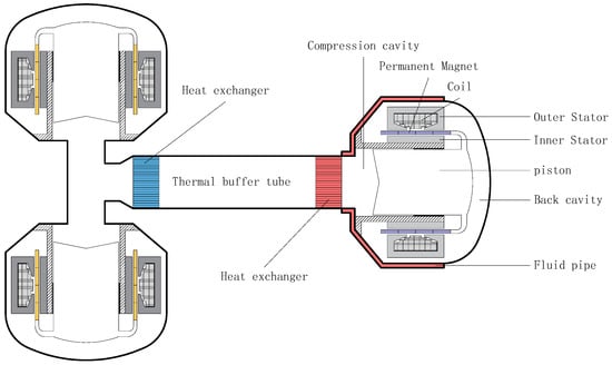
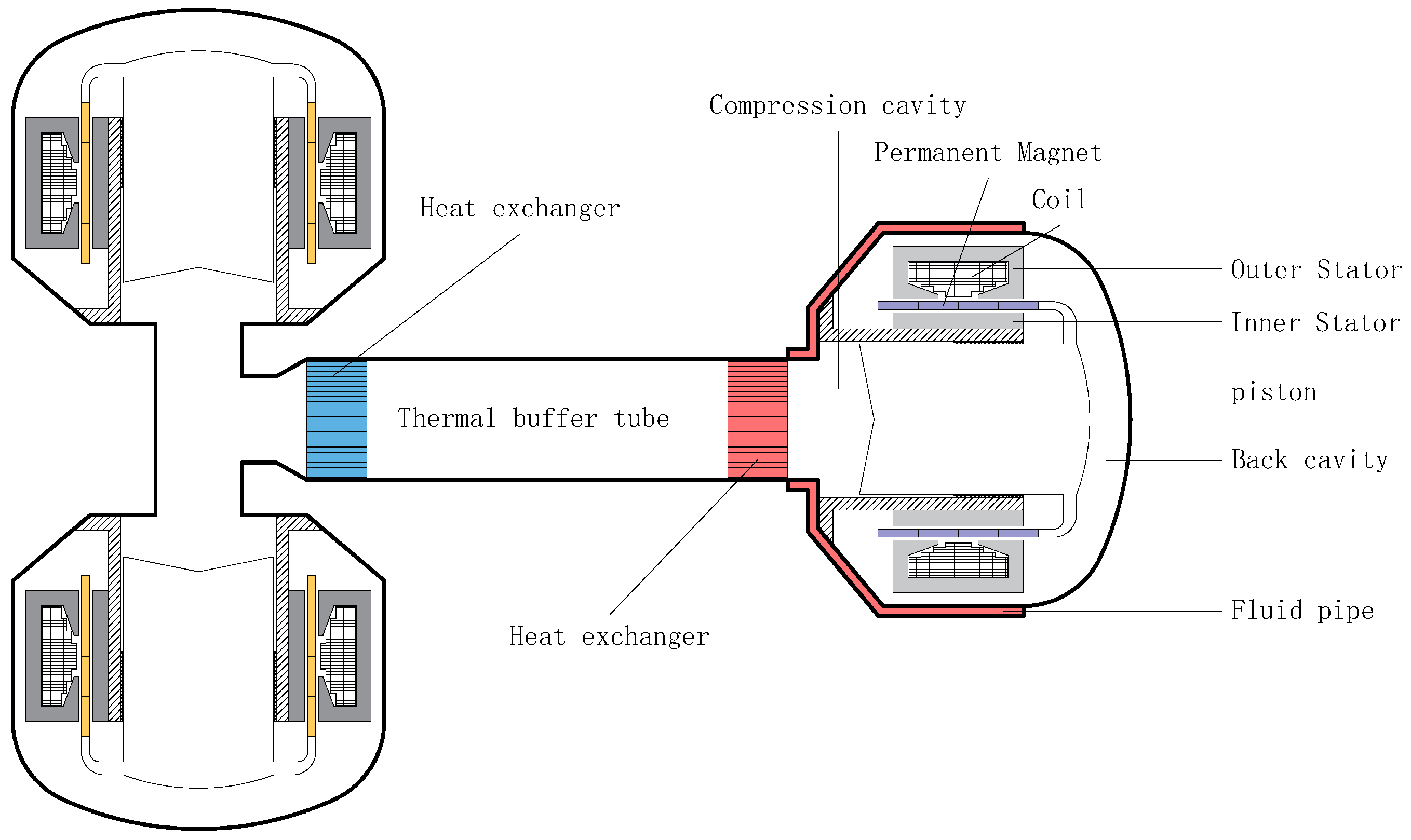
A schematic diagram of the constructed linear alternator dynamic testing system is shown in Figure 3, which mainly consists of opposed compressors, a room-temperature heat exchanger, a thermal buffer tube, a high-temperature heat exchanger, and the linear alternator under test. The compressors act as the driving source and generate pressure oscillations through reciprocating motion under electrical excitation, thereby driving the linear alternator to produce electrical power. The heat exchangers at both ends, together with the thermal buffer tube, ensure appropriate acoustic field conditions for both the compressors and the linear alternator, enabling efficient operation within their respective environments. During the experiments, an opposed linear compressor configuration was adopted. By adjusting the piston displacement of the compressors, different power matching conditions can be achieved while effectively reducing system vibration.
Figure 3.
Schematic diagram of the linear alternator dynamic testing system.
3. Results and Discussion
3.1. Static Test Results
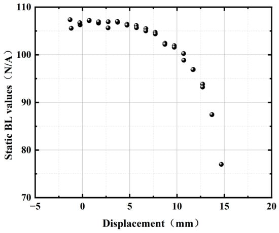
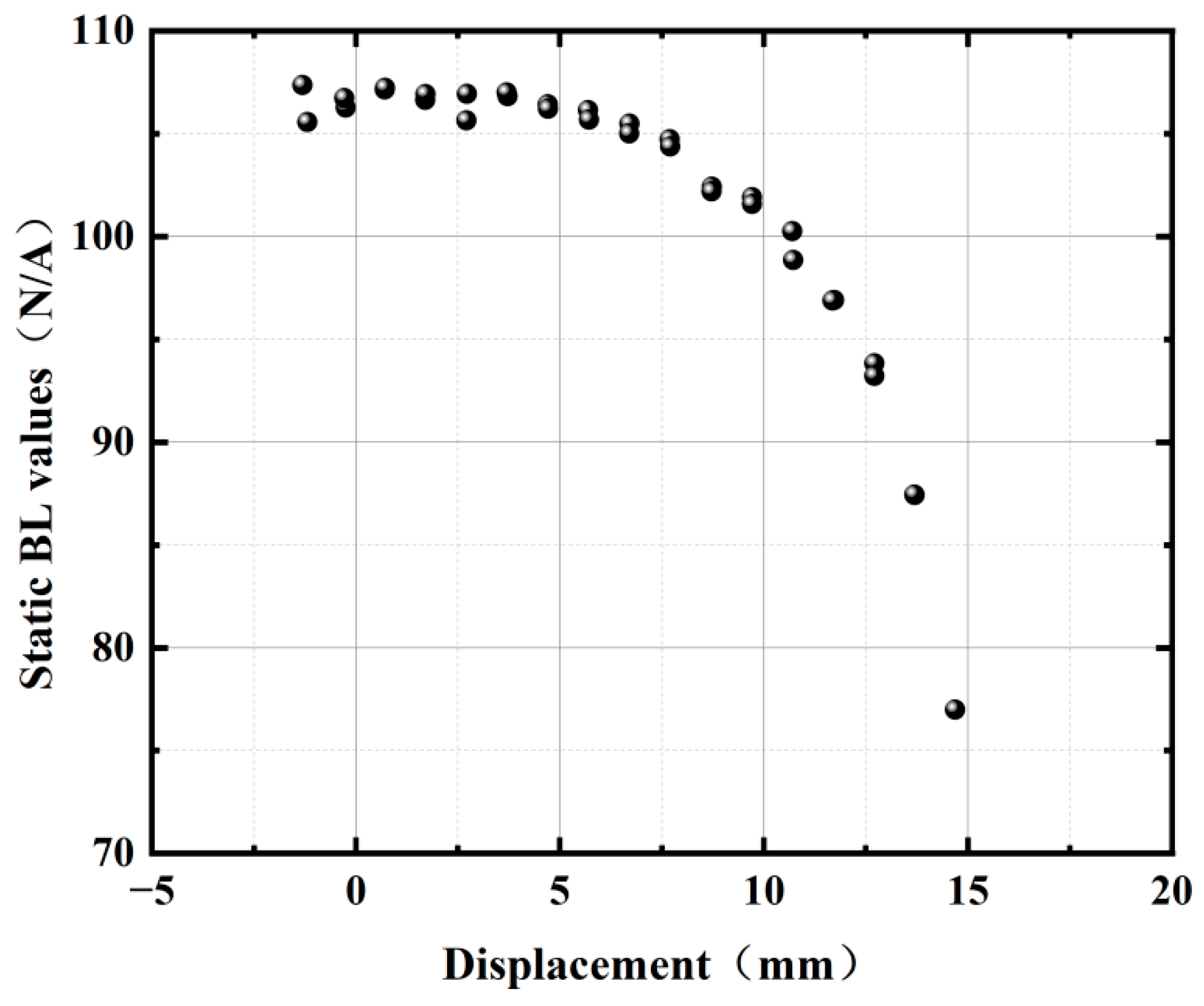
Using the static testing platform, the variation in the alternator force constant with piston displacement is obtained, as shown in Figure 4. It can be observed that when the piston is located at the equilibrium position, the alternator force constant is approximately 107 N/A. As the piston deviates from the equilibrium position, the alternator force constant gradually decreases due to the weakening of the magnetic field intensity. Moreover, the reduction becomes more pronounced with increasing displacement. When the piston reaches the maximum displacement of 15 mm, the alternator force constant decreases to approximately 77 N/A. In practice, the alternator force constant at the equilibrium position is typically selected as the reference for performance evaluation of the linear alternator.
Figure 4.
Variation in the alternator force constant with piston displacement.
The static test results indicate that the electromagnetic force constant is not strictly constant but varies with the piston displacement from the equilibrium position. To quantitatively characterize this position dependence, the measured data were fitted using a fourth-order polynomial, yielding
where x is the absolute displacement from the equilibrium position in mm and is expressed in N/A. The fitting coefficient of determination is R2 = 0.9904, indicating that the fitted curve provides a good representation of the measured position-dependent electromagnetic force constant.
However, the Sage model used in this study accepts the electromechanical conversion coefficient as a single parameter and cannot directly implement as a function of the instantaneous piston displacement. Therefore, to evaluate the influence of the position dependence of under the actual operating condition, an equivalent coefficient corresponding to the actual piston stroke was calculated.
Under sinusoidal oscillation, the piston displacement can be expressed as
where is the displacement amplitude and is the angular frequency.
Since the static test characterizes as a function of the absolute displacement from the equilibrium position, the corresponding position-dependent coefficient during dynamic operation is expressed as
For the operating condition considered in this study, the frequency and displacement amplitude were 60 Hz and 9 mm, respectively.
The instantaneous back electromotive force associated with the measured position-dependent characteristic can therefore be expressed as
Because the Sage model uses a constant electromechanical conversion coefficient, was replaced by a stroke-equivalent value for sinusoidal motion. This value was defined so that the fundamental component of the calculated back EMF matches that obtained from
where . The resulting coefficient is weighted by the square of piston velocity because positions traversed at higher velocity contribute more strongly to the fundamental back-EMF component.
Substituting the experimentally fitted relationship, together with the actual operating conditions of 60 Hz and 9 mm displacement amplitude, gives . Therefore, can be regarded as an equivalent parameter considering the static change in the position. It can then be further input into the Sage model for comparison.
3.2. Dynamic Test Results
After completing the measurement of the static electromagnetic parameters, dynamic performance tests of the linear alternator were conducted under the specified operating conditions. During the tests, helium with a mean pressure of 10.7 MPa was charged into the system, and the driving frequency of the opposed compressors was set to 60 Hz. To maintain appropriate operating conditions for both the compressors and the linear alternator, an industrial chiller and an oil temperature control unit were employed to establish external cooling loops. The outlet temperature of the cooling water was maintained at 20 °C, with a temperature difference between the inlet and outlet controlled within 5 °C. The oil temperature was set to 37 °C to reduce the temperature difference between the front and back chambers of the alternator. The opposed compressors were directly connected to a variable-frequency power supply. The two units were arranged in parallel with reverse connection, such that they operated with equal voltage amplitudes but a phase difference of 180°. The coil internal resistance was measured as 41.6 mΩ. The inductance was determined to be 24.49 mH through dynamic identification using Equation (5), based on the voltage and current amplitudes and phase angles measured at room temperature, rather than through an independent inductance measurement. For the external circuit of the linear alternator, a 4 Ω resistor was connected in series to simulate load power consumption, and a 272 μF capacitor was also connected in series to compensate for the coil inductance, ensuring near-resonant operation of the circuit.
Using this identified inductance and the series capacitance , the ideal inductor–capacitor (LC) resonance frequency is approximately 61.7 Hz. At the experimental frequency of 60 Hz, the residual reactance of the nominal series LC branch is estimated as
This indicates slight capacitive detuning from the nominal resonance condition. The tuning capacitor was selected based on the inductance calculated under the initial operating condition and remained fixed during operation. Temperature changes during operation may have altered the coil inductance, so the fixed capacitance may not have fully compensated for the operating inductance. The dynamic value was calculated using the voltage and current amplitudes and phase angles measured under the actual operating condition and therefore characterizes the alternator at 60 Hz under the observed detuning.
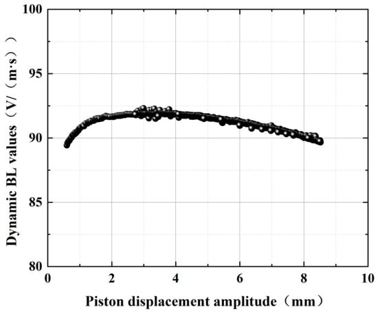
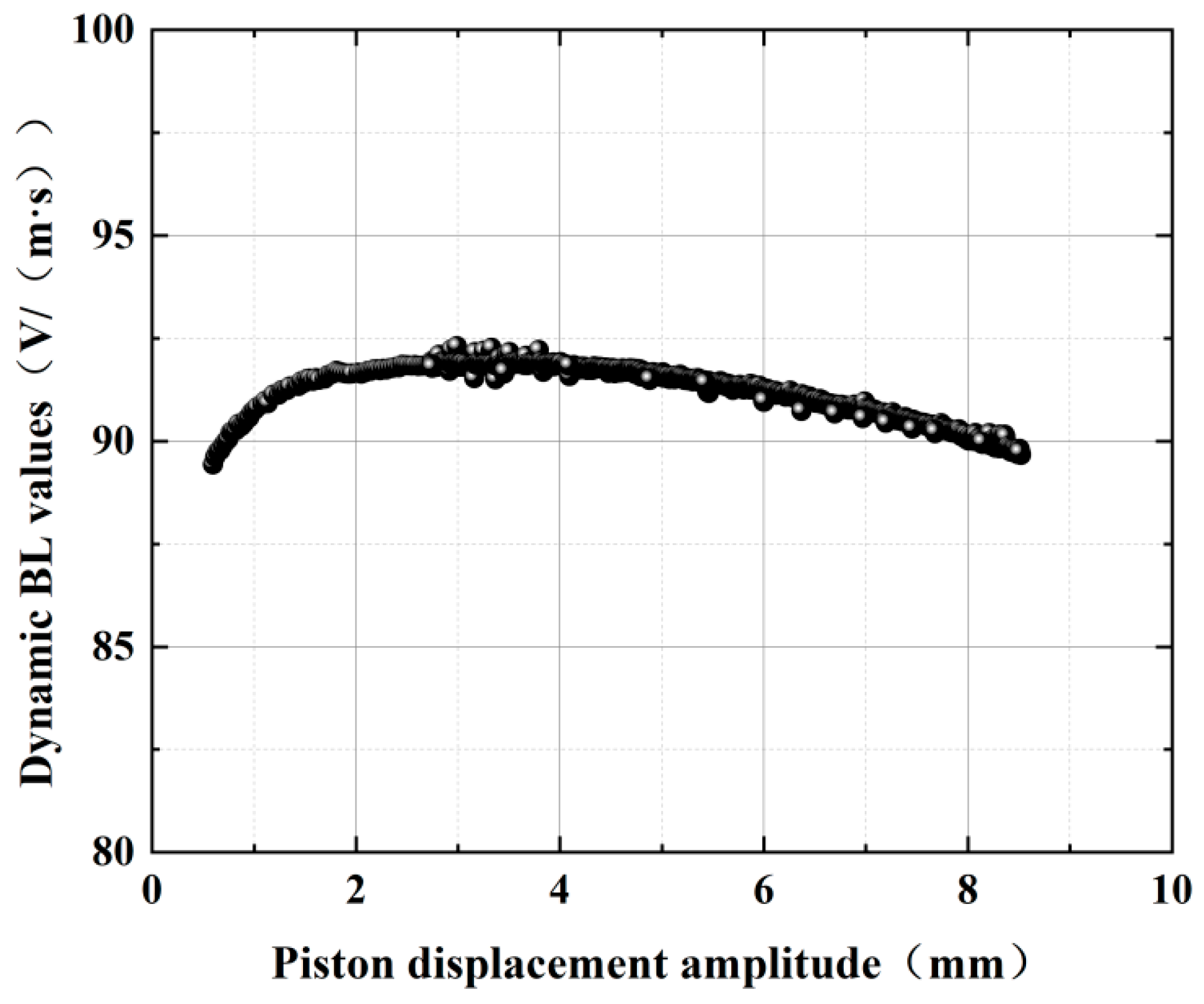
During the experiments, the response of the linear alternator and the overall test system under different displacement conditions was obtained by gradually increasing the driving voltage of the opposed compressors. The measured parameters were then substituted into Equations (3)–(6) to determine the variation in the electromotive force constant with displacement, as shown in Figure 5. The identified dynamic EMF constant varied from approximately 89 to 92 V·s/m across the measured displacement amplitudes. The subsequent Sage comparison used a value of 89.7 V·s/m.
Figure 5.
Variation in the electromotive force constant with piston displacement.
In Section 2.2, the expressions for the dynamic inductance and EMF constant were derived by neglecting the internal resistance. To assess the validity of this approximation, the parameters identified with and without the internal-resistance term were compared, as described below.
The internal resistance of the alternator coil was measured as , whereas the external load resistance was . Thus, , indicating that the coil resistance is small relative to the external load under the tested condition. To quantify the effect of neglecting , the dynamic inductance and EMF constant were calculated both with and without the internal-resistance term, using the measured voltage and current amplitudes and phase angles. When was neglected, Equations (5) and (6) yielded and V·s/m respectively. When was included in the circuit equation, the corresponding values were and V·s/m. The relative differences were 0.06% for inductance and 2.28% for the EMF constant. These results indicate that neglecting the coil resistance has a negligible effect on the identified inductance and a limited effect on the EMF constant under the tested condition. The approximation should be reassessed for operating conditions with a substantially lower load resistance.
Under ideal reciprocal electromechanical conversion, the force constant BL and the EMF constant are numerically equal when expressed in consistent units of the International System of Units (SI). In this study, the static force constant was determined from quasi-static force measurements under DC excitation, whereas the dynamic EMF constant was identified from the measured voltage and current amplitudes, their phase relationships, and the piston velocity during oscillatory operation. The equilibrium-position static force constant was approximately 107 N/A, while the representative dynamic EMF constant was 89.7 V·s/m, approximately 16.2% lower than the static value. This comparison indicates a difference between the parameters obtained using the two identification procedures; the possible contributing factors are discussed in Section 3.3.
3.3. Comparison of Simulation Results
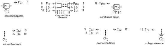
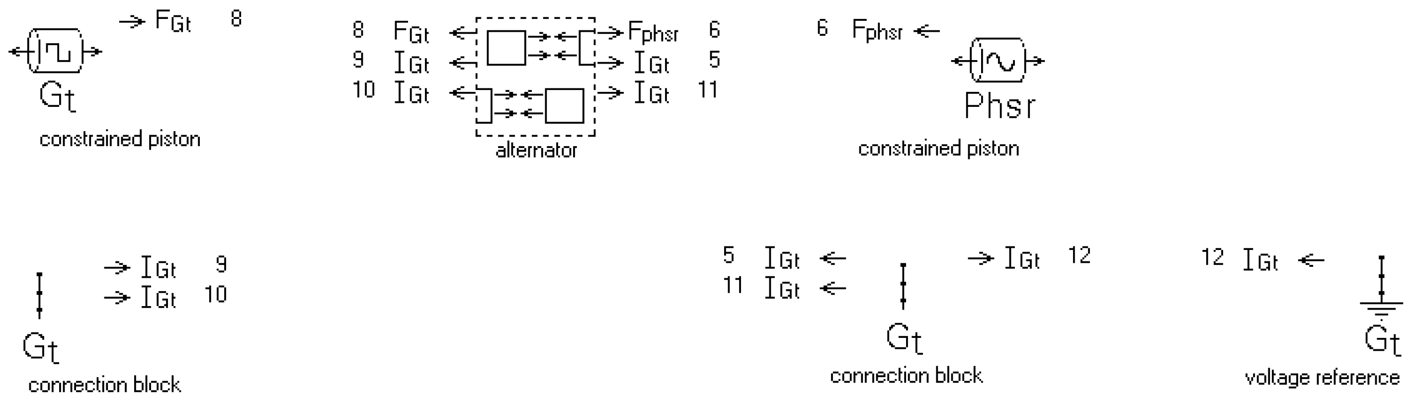
To compare the accuracy of the alternator force constant and the electromotive force constant in characterizing alternator performance, a computational model of the electrical circuit of the linear alternator is developed using the regenerative thermodynamic simulation software Sage 10, as shown in Figure 6. In this model, it includes power pistons, electromechanical conversion components, motor resistors and inductors, external load resistors, and tuning capacitors. Among them, the constrained piston is used to represent the alternator piston, and the transducer serves as the electromechanical conversion component to simulate the conversion between mechanical and electrical energy. The Remotor is employed to represent the internal resistance of the alternator, while the inductor models the coil inductance. The external load resistance is represented by Reo, and the tuning capacitor is modeled by a capacitor component. The parameters of each component, as well as the electromechanical conversion coefficients, are assigned according to the experimental operating conditions. The operating parameters of the linear alternator used in the Sage model are summarized in Table 1.
Figure 6.
Schematic diagram of the linear alternator circuit in Sage. The arrows indicate electrical connections and force connections between components.
Table 1.
Linear alternator operating parameters.
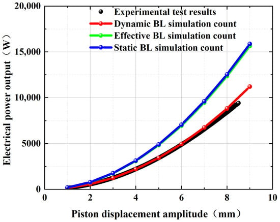
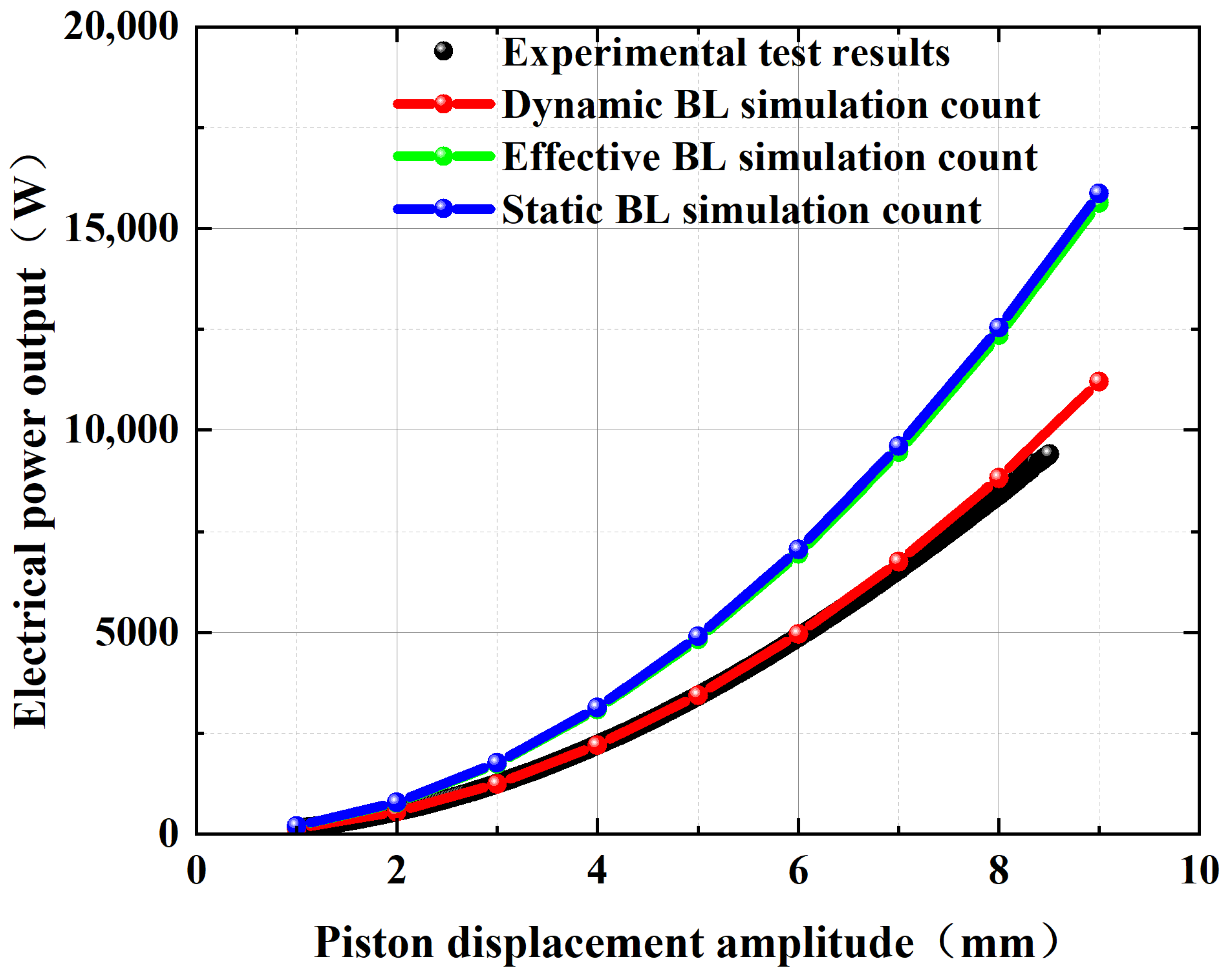
The equilibrium-position static force constant, the stroke-equivalent static force constant, and the dynamically identified EMF constant were separately used as the electromechanical coupling parameter in the Sage model. Figure 7 compares the resulting electrical-power estimates with the experimental measurements. The two static-parameter curves are close to each other, indicating that accounting for the measured displacement dependence of the static force constant has little effect on calculated power over the tested range. The dynamic-parameter curve agrees more closely with the measured power.
Figure 7.
Comparison of simulation and experimental data.
For quantitative comparison, the simulated power was linearly interpolated to the displacement values corresponding to 1876 experimental data points. The model using the dynamic EMF constant of 89.7 V·s/m yielded a mean absolute error (MAE) of 159.07 W, a root mean square error (RMSE) of 231.72 W, and a mean absolute percentage error (MAPE) of 2.60%. The corresponding MAPE values obtained using the equilibrium-position and stroke-equivalent static force constants were 45.94% and 43.67%, respectively. The dynamic-parameter model therefore showed substantially closer agreement with the measured electrical power under the investigated operating condition.
The limited improvement obtained with the stroke-equivalent static parameter is consistent with its value of 106.16 N/A, which is close to the equilibrium-position value of 107 N/A. Accordingly, the two static parameters produced nearly identical power predictions. Accounting for the measured position dependence of over the investigated stroke was therefore insufficient to resolve the discrepancy between the static-parameter predictions and the experimental measurements.
Before interpreting the static–dynamic parameter difference in terms of physical mechanisms, the effects of the identification procedure and the available measurement uncertainty estimates were considered. The influence of coil resistance was evaluated separately in Section 3.2. Voltage and current were consistently expressed as peak fundamental amplitudes, avoiding a mismatch between peak and root-mean-square (RMS) values. The velocity amplitude and phase reference were verified against the synchronized motion and electrical measurements. The corrected identification equations were then used to calculate the dynamic EMF constant and the corresponding simulation error metrics reported here.
Subject to this verification, the remaining difference may reflect the electromagnetic conditions represented by the two methods. Static testing characterizes the force–current relationship under quasi-static DC excitation, whereas dynamic identification determines an effective electromechanical coupling parameter during oscillatory operation. Eddy-current effects, magnetic nonlinearity, current loading, and parameter variations over the oscillation cycle may contribute to this difference. The present measurements cannot quantitatively separate these contributions, so no individual mechanism is identified as the dominant cause.
The methods also differ in their experimental requirements and the information they provide. Static characterization requires force measurement, piston positioning, and DC excitation and determines the position dependence of the force constant. Dynamic identification avoids direct force measurement during oscillatory operation but requires synchronized electrical and piston-motion measurements, together with fundamental amplitude and phase extraction. Its potential advantage is the determination of an effective parameter under the operating conditions relevant to power prediction. The present comparison is limited to one alternator and the investigated frequency and external circuit; further validation across frequencies, loads, and alternators is needed to establish broader applicability.
4. Conclusions
A circuit-resonance-based procedure was developed to identify the dynamic inductance and EMF constant of a laboratory-scale linear alternator from simultaneously measured voltage and current amplitudes and their phase relationship during oscillatory operation. Static measurements showed that the force constant varies with piston position; however, the stroke-equivalent static force constant calculated for the investigated 9 mm displacement amplitude was 106.16 N/A, close to the equilibrium-position value of 107 N/A. Under the investigated operating condition of 60 Hz, a 4 Ω external load, and a 272 μF series capacitor, the dynamically identified EMF constant was approximately 89.7 V·s/m. When this parameter was used in the Sage model, the predicted electrical power showed closer agreement with 1876 experimental data points than predictions based on either the equilibrium-position or stroke-equivalent static force constant. The dynamic-parameter model yielded an MAE of 159.07 W, an RMSE of 231.72 W, and a MAPE of 2.60%, whereas the corresponding MAPEs for the equilibrium-position and stroke-equivalent static parameters were 45.94% and 43.67%, respectively. These results indicate that, for the tested alternator and operating condition, an electromechanical parameter identified during oscillatory operation provides a more representative input for electrical-power prediction than the static parameters considered here. However, the present validation is limited to one alternator, one operating frequency, and one external load. Further measurements over broader frequency and load ranges, together with tests on additional alternators and a more comprehensive uncertainty assessment of phase-dependent parameter identification, are required to evaluate the robustness and general applicability of the method.
Author Contributions
Conceptualization, X.Z.; methodology, X.Z.; software, X.Z. and L.Z.; validation, L.Z., Y.C. and Y.S.; formal analysis, X.Z. and Y.C.; investigation, X.Z.; resources, Y.C. and Y.S.; data curation, X.Z.; writing—original draft preparation, X.Z.; writing—review and editing, Y.S. and Y.C.; visualization, X.Z.; funding acquisition, Y.C. and Y.S. All authors have read and agreed to the published version of the manuscript.
Funding
This work was financially supported by the Institute-Level Recruited Talent Fund of Technical Institute of Physics and Chemistry, Chinese Academy of Sciences (Grant No. E5ALD101) and the Key Research Program of the Key Laboratory of Cryogenic Science and Technology.
Data Availability Statement
The original contributions presented in this study are included in the article. Further inquiries can be directed to the corresponding author.
Acknowledgments
The authors acknowledge the technical support provided by the Key Laboratory of Cryogenic Science and Technology, Technical Institute of Physics and Chemistry, Chinese Academy of Sciences, and the use of Sage for system-level simulation and electrical-power prediction.
Conflicts of Interest
The authors declare no conflicts of interest.
Abbreviations
The following abbreviations are used in this manuscript:
| FPSG | Free-piston Stirling Generator |
| EMF | Electromotive Force |
| NASA | National Aeronautics and Space Administration |
| FFT | Fast Fourier Transform |
| DC | Direct Current |
| LC | Inductor–Capacitor |
| SI | International System of Units |
| MAE | Mean Absolute Error |
| RMSE | Root Mean Square Error |
| MAPE | Mean Absolute Percentage Error |
| RMS | Root Mean Square |
References
- Beale, W.T. Free-Piston Stirling Engines—A Progress Report; NASA Technical Report; NASA Lewis Research Center: Cleveland, OH, USA, 1969.
- Nasar, S.A.; Chen, C. Study of Free-Piston Stirling Engine Driven Linear Alternators; NASA Contractor Report NASA-CR-181425; NASA Lewis Research Center: Cleveland, OH, USA, 1987.
- Zare, S.; Tavakolpour-Saleh, A.R. Free piston Stirling engines: A review. Int. J. Energy Res. 2019, 43, 6343–6368. [Google Scholar] [CrossRef] [Scilit]
- Rauch, J.; Madi, F.; Kankam, M.; Santiago, W. A Free-Piston Stirling Engine/Linear Alternator Controls and Load Interaction Test Facility; SAE Technical Paper 929264; SAE International: Warrendale, PA, USA, 1992. [Google Scholar] [CrossRef] [Scilit]
- Zheng, J.; Huang, Y.; Wu, H.; Zheng, P. Design of a transverse-flux permanent-magnet linear generator and controller for use with a free-piston Stirling engine. Chin. J. Mech. Eng. 2016, 29, 832–842. [Google Scholar] [CrossRef] [Scilit]
- Oros (Pop), T.S.; Berinde, I. The study, design and simulation of a free piston Stirling engine linear alternator. Carpathian J. Electr. Eng. 2014, 8, 87–95. [Google Scholar]
- Rojo, J.F.G.; Lluesma-Rodríguez, F.; Sánchez, D.F.; Sabogal, A.P.; Pérez, G.R. Validation of a linear motor for hyperloop applications using a 3-axis static test bench. In Proceedings of the 13th International Symposium on Linear Drives for Industry Applications (LDIA); IEEE: New York, NY, USA, 2021; pp. 1–4. [Google Scholar]
- Jansen, J.W.; Van Lierop, C.M.M.; Lomonova, E.A.; Vandenput, A.J.A. Magnetically levitated planar actuator with moving magnets. IEEE Trans. Ind. Appl. 2008, 44, 1108–1115. [Google Scholar] [CrossRef] [Scilit]
- Luan, Z.Q.; Ji, H.Y.; Yang, Q.D. Research and development of a test platform for synthetic performance parameters of linear motors. Adv. Mater. Res. 2011, 383–390, 4486–4491. [Google Scholar] [CrossRef] [Scilit]
- Qiu, S.; Wang, H. Design of linear generator test platform and data acquisition system. Electr. Meas. Instrum. 2020, 57, 125–130. [Google Scholar] [CrossRef]
- Li, T. Research on Testing System of Permanent Magnet Synchronous Linear Motor. Master’s Thesis, Nanjing University of Aeronautics and Astronautics, Nanjing, China, 2020. [Google Scholar] [CrossRef]
- Liu, N. Research on Performance Parameters and Characteristic Test Method of Permanent Magnet Synchronous Linear Motor System. Master’s Thesis, Shenzhen University, Shenzhen, China, 2023. [Google Scholar] [CrossRef]
- Guo, R. Design and Analysis of Permanent Magnet Linear Oscillation Machine for Stirling Power Generation System. Master’s Thesis, Southeast University, Nanjing, China, 2020. [Google Scholar] [CrossRef]
- Wang, C. Optimized Design of Permanent Magnet Linear Generator for Wave Power Generation Based on Halbach Array. Master’s Thesis, Jiangsu University of Science and Technology, Zhenjiang, China, 2023. [Google Scholar] [CrossRef]
- Sun, M. Thrust Quality and Loss Optimization of Permanent Magnet Synchronous Linear Motor Based on Equivalent Magnetic Network Model Cluster. Master’s Thesis, Hefei University of Technology, Hefei, China, 2024. [Google Scholar] [CrossRef]
- Tang, T.; Xuan, L.; Liang, W.; Sun, Y.; Liu, J. Performance simulation and measurement of linear motors for free-piston Stirling coolers. Diesel Engine 2019, 41, 52–55. [Google Scholar]
- Jia, Z.; Wang, R.; Hu, J.; Zhang, L.; Wu, Z.; Chen, Y.; Luo, E. Study on the coupling between engine and alternator in a free-piston Stirling generator. Appl. Therm. Eng. 2022, 217, 119222. [Google Scholar] [CrossRef] [Scilit]
- Xiao, L.; Wu, Z.; Zhu, Q.; Jia, Z.; Zhao, D.; Hu, J.; Zhu, S.; Luo, E. Dynamic response of a dual-opposed free-piston Stirling generator. Energy 2023, 284, 129253. [Google Scholar] [CrossRef] [Scilit]
- Jia, Z.; Wang, R.; Hu, J.; Zhang, L.; Wu, Z.; Chen, Y.; Luo, E. Theoretical and experimental study of free piston Stirling generator for high cold end temperatures. Energy 2024, 289, 129841. [Google Scholar] [CrossRef] [Scilit]
- Kim, D.-J.; Sim, K. Linear Dynamic Analysis of Free-Piston Stirling Engines on Operable Charge Pressure and Working Frequency along with Experimental Verifications. Appl. Sci. 2021, 11, 5205. [Google Scholar] [CrossRef] [Scilit]
- Chen, P.; Deng, C.; Luo, X.; Ye, W.; Hu, L.; Wang, X.; Liu, Y. Performance optimization of a free piston Stirling engine using the self-directed online machine learning optimization approach. Appl. Therm. Eng. 2024, 236, 121482. [Google Scholar] [CrossRef] [Scilit]
- Cheng, C.-H.; Lin, Y.-T. Computational Optimization of Free-Piston Stirling Engine by Variable-Step Simplified Conjugate Gradient Method with Compatible Strategies. Energies 2022, 15, 3569. [Google Scholar] [CrossRef] [Scilit]
- Chen, P.; Zhong, G.; Niu, Y.; Liu, Y. Performance optimization of a free piston Stirling engine using multi-section regenerators based on the response surface methodology. Energy 2022, 261, 125221. [Google Scholar] [CrossRef] [Scilit]



Disclaimer/Publisher’s Note: The statements, opinions and data contained in all publications are solely those of the individual author(s) and contributor(s) and not of MDPI and/or the editor(s). MDPI and/or the editor(s) disclaim responsibility for any injury to people or property resulting from any ideas, methods, instructions or products referred to in the content. |
© 2026 by the authors. Licensee MDPI, Basel, Switzerland. This article is an open access article distributed under the terms and conditions of the Creative Commons Attribution (CC BY) license.