


Abstract
Temporal mismatches between geothermal output and user demand limit resource utilization, whereas thermal energy storage (TES) can decouple heat production from consumption. This review organizes geothermal–TES coupling by resource depth and answers four engineering questions. First, temperature, duration, geology, and end-use requirements determine compatibility: water tanks and low-temperature phase-change materials are preferred for short-term regulation; BTES and ATES provide seasonal capacity where geology permits; and pressurized-water, molten-salt, or thermochemical systems are reserved for higher-temperature resources. Second, short-term TES primarily suppresses cycling and peak demand, whereas seasonal TES restores annual subsurface balance and raises geothermal-well utilization. Third, selection must jointly consider recovery efficiency, usable discharge temperature, auxiliary electricity, land and drilling requirements, technology readiness level, and cost rather than storage density alone. Fourth, coupling introduces constraints that are absent from stand-alone components, including groundwater advection, thermal breakthrough, corrosion and scaling, well-flow limits, and temperature matching. Nordic experience demonstrates the value of integrating underground TES with district heating and cooling, but economic feasibility remains site specific. Indicative storage-capacity costs are approximately 0.1–1.3 EUR/kWhth for ATES, 0.6–3 EUR/kWhth for BTES, and 0.5–1.7 EUR/kWhth for PTES, with strong scale and boundary dependence. A compatibility matrix, maturity assessment, and staged development roadmap are provided to support system selection and research prioritization.
1. Introduction
Against the backdrop of an accelerating global transition toward low-carbon energy systems, the heating sector remains a major consumer of fossil fuels and a significant source of greenhouse-gas emissions [1]. Demand for space heating and domestic hot water exhibits pronounced hourly fluctuations and seasonal variations [2,3]. As renewable-energy substitution and the electrification of heating advance, seasonal and peak-load characteristics will exert an increasingly strong influence on energy-system balancing. The decarbonization of heating therefore requires greater flexibility and coordination between supply and demand through heat pumps, thermal energy storage (TES), and load shifting [4,5]. Compared with other renewable sources, geothermal energy provides stable and continuous output across a broad temperature range and can supply low-carbon energy for building heating and cooling, district heating, industrial process heat, and power generation [6,7]. However, the relatively stable output of geothermal resources does not inherently match dynamic and seasonal heating and cooling loads on the demand side [8]. Peak demand during the heating season, low demand during the non-heating season, and annual imbalances between heating and cooling may cause subsurface thermal imbalance and system-performance degradation while complicating equipment sizing and operational optimization [9,10]. Consequently, a key challenge for the large-scale and sustainable deployment of geothermal heating is to use seasonal TES to redistribute heat over time while preventing persistent subsurface temperature decline and maintaining the long-term stability of geothermal-resource exploitation [11].
Geothermal depth terminology is not universal and should be interpreted together with temperature, geology, and development mode. In this review, shallow geothermal energy denotes near-surface resources generally within about 200 m and commonly below 25 °C. Medium-deep resources are treated as approximately 200–3000 m for consistency with the reviewed literature, while acknowledging that European classifications often use 400–1000 m for the middle-deep interval and regard depths beyond about 400 m as deep geothermal [12,13,14,15,16]. Deep resources are treated here as resources developed at depths greater than approximately 3000 m in the present framework. These depth bands are organizational rather than prescriptive. Shallow resources are used through both closed-loop ground heat exchangers and open-loop groundwater systems. Medium-deep and deep resources likewise include open-loop hydrothermal production–reinjection doublets as well as closed-loop coaxial or U-tube borehole heat exchangers; at 500–1000 m, coaxial, single U-tube, and double U-tube configurations exhibit materially different heat extraction and pumping penalties [17]. Resource temperature, productivity, reinjection feasibility, and end-use temperature therefore take precedence over depth alone when selecting TES.
TES decouples heat production from consumption through charging, storage, and discharging processes [18], thereby providing a direct means of addressing these mismatches. Short-term TES can balance heat supply and demand from hourly to intra-day timescales, shift and shave peak loads, reduce frequent start–stop cycling of heating equipment, and improve supply stability. Seasonal TES can store surplus solar heat, industrial waste heat, and other heat available during the non-heating season for use during the heating season; subsurface heat injection can also alleviate long-term thermal imbalance in ground-source heat-pump systems [19,20]. According to the storage mechanism, TES comprises sensible, latent, and thermochemical heat storage [21]. According to the storage domain, it also includes borehole thermal energy storage (BTES), aquifer thermal energy storage (ATES), and other large-scale underground storage options [22]. These technologies differ in operating temperature, storage duration, energy density, and engineering requirements, and therefore exhibit different degrees of compatibility with shallow, medium-deep, and deep geothermal systems. Establishing these compatibility relationships is the central focus of research on geothermal–TES coupling. As shown in Figure 1, geothermal resources at different depths can be connected to surface and underground TES through charging, direct-supply, discharging, and reinjection pathways.
Figure 1.
Conceptual framework and heat-flow pathways for geothermal energy coupled with TES. The geothermal-resource column includes open-loop hydrothermal production–reinjection systems and closed-loop ground or downhole heat exchangers; both can connect to surface TES and underground TES through charging, direct-supply, discharging, and reinjection pathways.
Recent research on shallow geothermal energy has shifted from the performance of stand-alone heat pumps toward the coordinated operation of heat pumps and storage. Saleem et al. [23] systematically reviewed configurations coupling sensible, latent, and hybrid storage with ground-source heat pumps and showed that TES can retain energy available during low-load periods, meet peak heating and cooling demand, and mitigate subsurface thermal imbalance. Through studies of shallow-geothermal district heating and cooling networks and associated case studies, Figueira et al. [24] demonstrated that shared ground heat-exchange infrastructure and district energy networks can connect users with complementary load profiles, although long-term subsurface heat balance must still be considered in system design. These studies indicate that the principal integration routes for shallow geothermal energy and TES should include short-term heat-pump regulation, seasonal underground TES, and solar-assisted heat replenishment, rather than treating the ground heat exchanger as an unlimited heat source.
For medium-deep geothermal energy, research is progressively moving from continuous heat extraction toward the coordinated management of extraction, storage, and heat replenishment. Deng et al. [25] investigated the thermal-storage characteristics of a deep borehole heat exchanger under intermittent operation and found that transient heat storage in the wellbore can enhance short-term heat-extraction capacity and broaden the adjustable range of thermal output. Huang et al. [26] and Ma et al. [27] analyzed heat-supply and heat-storage processes in medium-deep U-shaped wells and medium-deep borehole heat exchangers, respectively, showing that heat replenishment during the non-heating season and appropriate operating parameters can improve subsequent heat-extraction performance. Wang et al. [10] further examined the long-term coupled operation of a solar-assisted deep-borehole ground-source heat pump and seasonal borehole TES, demonstrating that subsurface heat replenishment can mitigate temperature decline and improve long-term energy-saving potential. Thus, the essential role of TES in medium-deep geothermal systems is not simply to add a storage tank, but to establish an operating sequence comprising stable heat extraction, short-term peak-load regulation, heat replenishment during the non-heating season, and heat release during the heating season.
Large-scale underground TES provides an additional pathway for seasonal regulation of geothermal systems. Based on a full-scale project, Zhang et al. [22] investigated high-temperature aquifer TES and characterized heating-and-storage, isothermal-storage, and long-term cycling processes, showing that both operating-cycle duration and standby time affect thermal performance. Underground storage can receive heat from medium-deep geothermal resources, solar energy, and industrial waste heat, thereby enabling a sequence of medium-deep heat extraction, shallow subsurface storage, and heating-season utilization. Its feasibility, however, remains constrained by formation thermophysical properties, groundwater flow, inter-well interference, and environmental-safety requirements. In deep high-temperature geothermal applications, TES can also be integrated into the power cycle or waste-heat recovery train to coordinate electricity generation, industrial heat supply, and building heating, while supporting cascade utilization across multiple temperature levels.
Although extensive studies have investigated TES in ground-source heat-pump systems, geological heat storage, deep borehole heat exchangers, and geothermal-reservoir simulation, four questions remain unresolved. RQ1: Which TES technologies are compatible with shallow, medium-deep, and deep geothermal resources when temperature, geology, duration, and end use are considered together? RQ2: Where is the functional boundary between short-term peak regulation and seasonal subsurface storage? RQ3: Which technical, economic, and maturity indicators should govern technology selection? RQ4: Which new constraints emerge after geothermal and TES components are coupled, and how should they be managed? These questions define the analytical structure of the review.
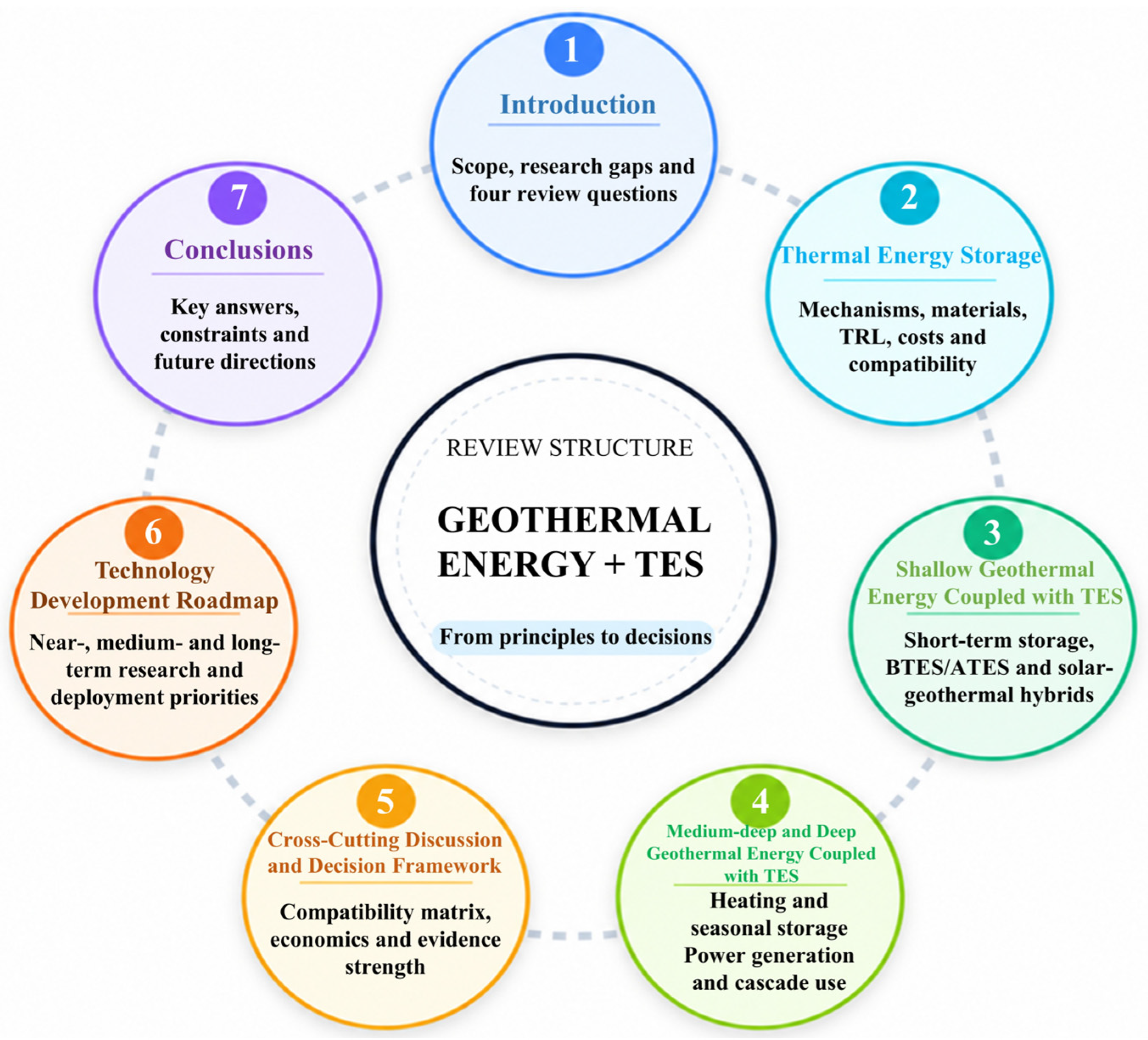
To answer these questions, Section 2 compares TES mechanisms, costs, maturity, and geothermal compatibility; Section 3 evaluates shallow systems across hourly and seasonal timescales; Section 4 examines medium-deep and deep heating, power, and cascade configurations; Section 5 integrates the evidence into a decision framework and economic discussion; Section 6 provides a prioritized technology roadmap; and Section 7 states the answers and engineering implications. The compact review map below links each question to its evidence base and decision output (Figure 2).
This structured narrative review was compiled from searches of Web of Science Core Collection, Scopus, and Google Scholar, supplemented by backward and forward citation checking, for English-language publications available through August 2026. Search concepts combined geothermal energy, ground-source heat pumps, hydrothermal doublets, and deep borehole heat exchangers with thermal energy storage, seasonal storage, buffer tanks, phase-change materials, thermochemical storage, BTES, ATES, and reservoir storage. Records were retained when a geothermal resource or heat-pump subsystem exchanged heat with a defined storage component or geological storage domain and reported transferable design, performance, economic, or maturity information. Duplicate DOI/title records were removed; titles and abstracts were screened before full-text assessment. For each retained source, the review recorded configuration, depth, temperature, duration, system boundary, scale, evidence type, principal metric, and stated limitation. Evidence was identified as numerical/analytical, laboratory, pilot/demonstration, or field/commercial. Because definitions and system boundaries remain heterogeneous, no pooled meta-analysis was performed.
The review distinguishes three coupling classes: (i) surface TES downstream of geothermal production; (ii) dedicated underground TES, such as BTES or ATES, charged by a geothermal or heat-pump system; and (iii) a geological reservoir that acts as both the geothermal resource and the storage domain. Adjacent solar, waste-heat, compressed-air, Carnot-battery, and multi-energy concepts are included only when they change the sizing, charging, or dispatch of a geothermal–TES system.
Figure 2.
Circular framework illustrating the structure and thematic organization of this review.
2. Thermal Energy Storage
2.1. Principles and Classification of TES
TES is an energy-management technology that temporarily stores heat or cold in a controlled manner and releases it when required [28]. A complete TES process comprises charging, storage, and discharging [29]. During charging, heat from geothermal energy, solar energy, industrial waste heat, or electricity conversion is transferred to the storage medium. During storage, the energy is retained through a change in medium temperature, a phase transition, or a reversible reaction. During discharging, heat is delivered to the user through heat exchange or a reverse reaction. The essential function of TES is not to generate heat but to redistribute it over time, thereby allowing the heat source to operate relatively steadily while meeting variable end-use demand.
According to the storage mechanism, TES is generally classified as sensible heat storage, latent heat storage, or thermochemical heat storage [30]. Sensible heat storage stores energy by increasing or decreasing the temperature of a medium; the stored energy can be expressed as the product of medium mass, specific heat capacity, and temperature difference. This approach is conceptually simple, technologically mature, and compatible with widely available media such as water, soil and rock, concrete, and molten salts. Its energy density is comparatively low, however, and the storage temperature varies with the stored energy [31]. Latent heat storage uses the heat absorbed or released during melting, solidification, or another phase transition. Total storage capacity comprises sensible heat before and after the transition together with the latent heat of the transition. Because phase change generally occurs over a narrow temperature interval, latent heat storage provides a higher energy density than sensible heat storage at a relatively stable temperature, making it suitable for applications requiring tight temperature control or compact equipment [32]. Thermochemical heat storage stores reaction heat through adsorption, absorption, or reversible chemical reactions. External heat drives desorption or an endothermic reaction and separates the reactants during charging; adsorption, absorption, or the reverse reaction subsequently releases the heat [33]. If the reactants remain effectively separated during storage, most energy is retained as chemical potential, reducing long-term sensible heat losses and yielding a high theoretical energy density. Thermochemical storage is therefore better suited than sensible and latent storage to long-duration, high-density applications, although system complexity, reaction kinetics, material degradation, and cost still constrain commercialization [34].
TES can also be classified by duration. In the practical screening used here, storage periods shorter than 7 d represent short-term regulation, while 7–365 d represents medium-to-long-duration and seasonal operation; project-specific definitions may differ. Additional classifications distinguish operation below and at or above 100 °C, aboveground and underground implementation, and active and passive systems according to whether fluid transport is employed [35,36]. Figure 3 replaces qualitative labels with these numerical screening ranges. The thresholds are intended for initial comparison rather than as universal boundaries.
Figure 3.
TES classification using numerical screening ranges for operating temperature (<100 °C and ≥100 °C), storage duration (<7 d and 7–365 d), and storage mode.
This review applies three linked filters: storage mechanism, duration, and implementation. For geothermal systems, selection must also match source and delivery temperatures, geological conditions, system scale, technology readiness, and economics. Table 1 therefore adds indicative TRL and cost ranges together with representative sources. Costs use the capacity basis reported by the cited sources and should not be compared without checking project scale, temperature lift, system boundaries, land, drilling, and auxiliary equipment.
Table 1.
Performance, maturity, indicative cost, and geothermal compatibility of major TES technologies.
The technology-level comparison in Table 1 is complemented by the resource-level decision matrix in Table 2. The matrix integrates geothermal configuration, source temperature, storage timescale, preferred TES, principal value, dominant constraint, maturity, and economic screening. Section 2.2, Section 2.3, Section 2.4 and Section 2.5 then explain the mechanisms underlying these choices.
Table 2.
Geothermal–TES compatibility and decision matrix.
2.2. Sensible Heat Storage
The engineering value of sensible heat storage lies primarily in the wide availability of storage media, stable cycling behavior, relatively simple device configurations, and straightforward scale-up [37]. For a given application, the central task is not to reclassify the storage mechanism, but to determine the volumetric heat capacity, thermal conductivity, hydraulic resistance, thermal stability, and cost of the medium within the target temperature range, and then to match these properties with an appropriate tank, packed-bed, or embedded heat-exchanger configuration. Liquid media commonly provide both heat-storage and transport functions, whereas solid media require air, water, thermal oil, or molten salt as the heat-transfer fluid.
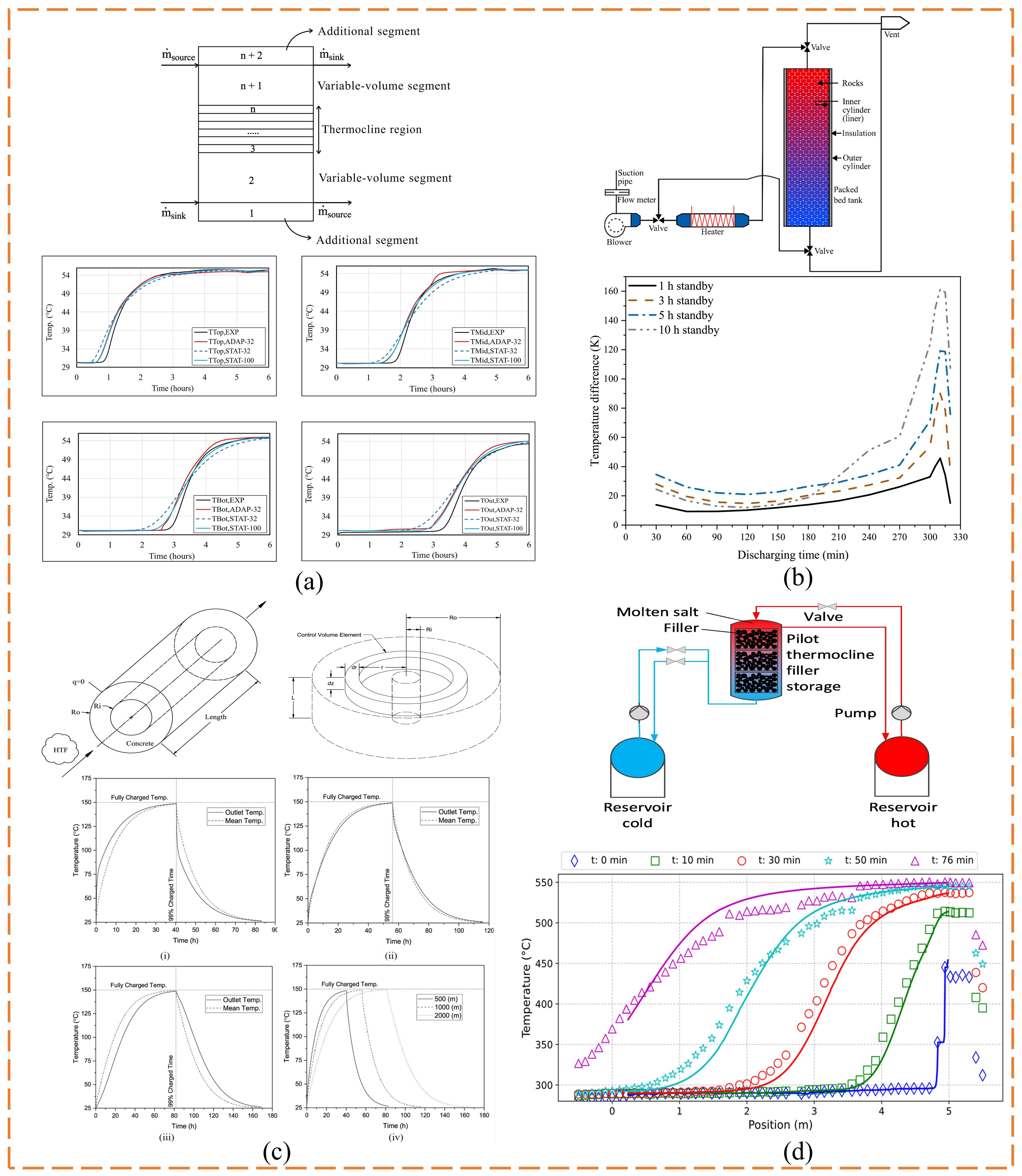
Water is the most mature sensible-heat-storage medium for building heating, domestic hot water, and low-temperature district heating networks. Water tanks may operate under fully mixed conditions or exploit density differences to establish a hot upper layer and a cold lower layer. The latter configuration maintains a high outlet temperature and heat quality by minimizing mixing within the thermocline [46]. During charging, hot water should enter the upper tank through a diffuser with minimal disturbance; during discharging, heat is withdrawn from the upper region while low-temperature return water is introduced at the bottom. Inlet-jet momentum, flow rate, diffuser design, tank aspect ratio, insulation level, and standby duration collectively determine thermocline thickness and stability [47]. Krüger et al. [48] investigated the effects of aspect ratio on thermocline evolution, energy efficiency, and exergy efficiency in large water-based storage tanks. A higher aspect ratio improved stratification stability but also increased the heat-transfer area and environmental heat loss, indicating that geometric design must balance stratification quality against thermal losses. Jodeiri et al. [49] combined experiments and numerical simulations to study the dynamic temperature field in a stratified water tank and proposed an adaptive-mesh model that tracks thermocline movement (Figure 4a). At a comparable prediction uncertainty, the method reduced computation time by approximately 55%, facilitating real-time simulation and control of tank–heat-pump systems. Overall, stratified water tanks are technologically mature and well suited to intra-day buffering and peak regulation in geothermal systems. For operation above 100 °C, however, pressurized vessels are required because of the boiling point of water.
Granular materials such as rock, gravel, and sand are commonly arranged as packed beds. During charging, a high-temperature heat-transfer fluid passes through the bed and transfers heat to the solid particles; during discharging, a cooler fluid absorbs the stored heat before leaving the bed [50]. These systems use inexpensive materials, tolerate a broad temperature range, and are suitable for large-capacity storage. Nevertheless, nonuniform particle shapes and size distributions can cause flow maldistribution, localized temperature differences, and additional pressure drop. Smaller particles increase the heat-transfer area but raise fan or pump energy consumption, whereas larger particles reduce pressure loss but may intensify intraparticle temperature gradients. Bed porosity, particle size, aspect ratio, flow direction, and insulation must therefore be designed concurrently. Kothari et al. [51] experimentally and numerically investigated a high-temperature magnetite rock–air packed bed, focusing on lateral temperature nonuniformity during standby and discharge (Figure 4b). Local heat losses amplified temperature-field instability through positive feedback between flow resistance and flow rate, and the instability intensified with standby duration. After a 10 h standby period, the maximum difference between rock temperature and outlet-air temperature during discharge reached 161 K. Accordingly, scale-up of packed beds must address sidewall heat loss and lateral thermo-fluid instability in addition to material heat capacity.
Concrete can serve simultaneously as the storage medium and structural body and is suitable for modular solid storage and fluid-in-tube/concrete heat-exchange units. Its advantages include abundant raw materials, relatively low cost, designable geometry, and solid-state stability over a broad temperature range. The principal limitations are modest thermal conductivity, dehydration at elevated temperature, thermal-cycling cracks, and degradation of the tube–matrix interface [52]. Aggregate type and volume fraction, water-to-binder ratio, fibers, and mineral admixtures jointly affect volumetric heat capacity, thermal conductivity, and cyclic durability; material formulation should therefore be optimized together with the actual temperature window and structural constraints. Shakeri et al. [53] investigated the integration of concrete sensible heat storage with an organic Rankine cycle driven by low-grade solar heat and optimized tube length, diameter, and flow distribution through parametric analysis (Figure 4c). With a storage-tube length of 2000 m and diameter of 0.4 m, concrete storage extended daily ORC operation from 3 h 10 min to 6 h 20 min, with only a slight reduction in total electricity generation. These results show that concrete storage can effectively extend the utilization period of low-grade heat while accommodating district-heating demand. For geothermal applications, concrete storage is best suited to medium- and low-temperature systems with moderate to large capacities; its durability under high-temperature geothermal conditions requires further experimental verification.
Molten salts are suitable for medium- and high-temperature sensible heat storage and can function as both the storage medium and heat-transfer fluid. Two-tank systems store hot and cold salt separately and provide distinct temperature boundaries but require more equipment and salt. Single-tank thermocline systems establish hot and cold zones within one vessel and may replace part of the molten salt with rock, ceramic, or refractory-brick filler to reduce cost [38]. Key operational concerns include salt solidification, material corrosion, thermocline degradation, filler thermal stress, and hydraulic pressure loss. Vera et al. [54] studied a pilot-scale molten-salt/clinker-brick structured thermocline storage system and validated a numerical model against dynamic cycling experiments (Figure 4d). The thermocline remained stable over repeated charge–discharge cycles, and the cut-off temperature affected thermocline thickness much more strongly than the mass flow rate, demonstrating that the operating temperature window is a major determinant of effective capacity and output quality. The operating range of molten-salt storage is compatible with the heat-source temperature of deep-geothermal power generation. However, corrosion and freezing increase operation and maintenance requirements, making this option uneconomic for shallow and medium-/low-temperature geothermal heating.
For geothermal utilization, sensible heat storage should provide a continuous match among the temperature levels of the storage medium, geothermal fluid, and end user. Shallow and medium-deep geothermal heating systems can preferentially use water tanks for intra-day buffering and peak-load regulation, thereby reducing heat-pump cycling and stabilizing geothermal-well flow. As storage duration, capacity, or temperature increases, rock packed beds, concrete modules, and other large-capacity solid-storage options may be considered. Comparative assessment should account for the effective temperature difference, outlet-temperature stability, heat loss, auxiliary energy consumption, land requirements, material lifetime, and levelized cost of useful discharged heat. Overall, sensible heat storage is most appropriate as the baseline, capacity-oriented option in coupled geothermal–TES systems, whereas latent and thermochemical storage can complement it where temperature stabilization or compactness is required.
Figure 4.
Sensible-storage progression from fast-response liquid storage to high-temperature solid storage: panel (a) links tank stratification to transient prediction [49]; panel (b) shows how standby losses create lateral instability in a rock bed [51]; panel (c) connects concrete geometry with extended ORC operation [53]; and panel (d) demonstrates thermocline preservation in a molten-salt/brick store [54]. The sequence highlights the trade-off between response, temperature capability, pressure loss, and construction complexity.
2.3. Latent Heat Storage
As shown in Figure 5, phase-change materials (PCMs) can be classified according to their physical state transition as solid–liquid, solid–solid, solid–gas, or liquid–gas materials. Composite PCMs can additionally be produced by combining a PCM with porous supports, thermally conductive fillers, or encapsulation materials [39]. Solid–gas and liquid–gas transitions generally involve large volume changes and stringent sealing requirements. Solid–solid PCMs avoid liquid leakage but usually offer relatively limited latent heat. By comparison, solid–liquid PCMs provide high energy density, a relatively stable transition temperature, and mature encapsulation methods and are therefore the most widely used class in TES systems [40]. Solid–liquid PCMs may be further divided by composition into organic, inorganic, and eutectic materials [55]. Organic PCMs include paraffins, fatty acids, fatty alcohols, and polyethylene glycols and typically exhibit good chemical stability, low corrosivity, and favorable cycling performance. Inorganic PCMs, principally salt hydrates and molten salts, generally have high volumetric energy density, comparatively high thermal conductivity, and nonflammability. Eutectic PCMs consist of two or more components at specified proportions and include organic–organic, inorganic–inorganic, and organic–inorganic systems; their major advantage is that the transition temperature can be adjusted through composition [56].
Figure 5.
Classification of phase-change materials by phase-transition mechanism and chemical composition [39].
A single PCM rarely satisfies the simultaneous requirements of storage capacity, heat-transfer rate, and long-term stability. Organic materials generally have low thermal conductivity and may leak or burn after melting. Inorganic materials such as salt hydrates are susceptible to supercooling, incongruent melting, phase separation, and corrosion. Although eutectics enable adjustment of the operating temperature, they may still exhibit low thermal conductivity, component segregation, and drift in phase-change behavior after repeated cycling [57]. Current enhancement methods fall into three principal categories. First, expanded graphite, graphene, metal foams, or highly conductive particles can establish heat-conduction networks and shorten charging and discharging times [58]. Second, porous frameworks, polymer supports, or encapsulation can restrict the flow of molten PCM and reduce leakage and component stratification [59]. Third, nucleating and thickening agents can be added to salt hydrates to reduce supercooling and inhibit solid-phase sedimentation, respectively [60]. Because thermal conductive fillers and supporting materials do not undergo phase change, excessive addition directly reduces latent-heat capacity. Material modification must therefore balance heat-transfer enhancement, shape stability, and storage density; no single formulation is universally optimal.
For organic paraffins, macroencapsulation can simultaneously confine the liquid phase and enlarge the heat-transfer area. Arslan and Ilbas [61] encapsulated two paraffins in cylindrical aluminum shells and compared encapsulated and non-encapsulated configurations in a tubular TES unit (Figure 6a,b). The aluminum shell confined molten paraffin to a fixed volume, reducing leakage risk, while its high thermal conductivity and enlarged surface accelerated charging. Over the same period, the stored energy of the two encapsulated paraffins increased by 60.5% and 50.7%, respectively. Thus, when leakage and external heat transfer are the dominant limitations, optimizing the encapsulation structure is more direct than simply adding conductive particles. Li et al. [62] investigated the combined effects of enclosure geometry and nickel-foam-enhanced conduction in a paraffin-based storage tank. They found that a conical tank with an upper-to-lower radius ratio of 2:1 reduced the complete melting time by 16.01% and increased the heat-storage rate by 11.68% relative to the reference configuration, indicating that storage-unit geometry should be designed together with porous conductive structures. For organic materials such as fatty acids, a porous conductive framework can improve both shape stabilization and internal heat transfer. Nguyen et al. [63] impregnated stearic acid into expanded-graphite pores and added Fe3O4 nanoparticles to produce a composite containing 80 wt.% stearic acid. Capillary forces in the expanded graphite retained the molten acid and established a continuous thermal conductive network, while Fe3O4 added photothermal and magnetothermal conversion functions. The composite had a latent heat of 152.4 J /g, favorable leakage resistance and cycling reliability, and a thermal conductivity of 2.546–7.912 W/(m·K), approximately 10.8–33.7 times that of pure stearic acid. A porous framework can therefore preserve a high PCM fraction while providing leakage control and enhanced conduction. Hu et al. [64] further combined the functions of fins and porous structures by embedding structured porous fins in PCM. Their pore-scale simulations showed that this configuration reduced the melting time by 62% compared with a finless unit and by 20% compared with conventional solid fins, while the fin thickness, number of porous layers, and material properties jointly affected the enhancement performance.
Figure 6.
Defect-specific enhancement of latent storage: (a) drawings of PCM capsules [61]; (b) effect of PCM encapsulation on the charging performance of the TESU [61]; (c) cooling curves used to evaluate nucleating-agent effects in the eutectic salt-hydrate PCM [65]; (d) DSC curves of the composite PCM before and after 200 thermal cycles [65]; (e) SEM pictures of fatty acid/EG CPCMs with different EG mass contents [66]; and (f) variations in thermal conductivity of CPCMs with different EG mass contents [66]. The panels should be read as three different failure modes rather than as directly comparable performance rankings.
For inorganic salt hydrates, nucleating and thickening agents must be used synergistically: the former provide heterogeneous nucleation sites that lower the nucleation barrier, whereas the latter increase melt viscosity and suppress solid settling. Ye et al. [65] prepared a Na2HPO4·12H2O–K2HPO4·3H2O eutectic composite supported by porous SiO2 and used Na2SiO3·9H2O as a nucleating agent (Figure 6c,d). Adding 6 wt.% K2HPO4·3H2O yielded a transition temperature of 25.1 °C and a melting enthalpy of 136.6 J/g, while 5 wt.% Na2SiO3·9H2O reduced the supercooling to 1.2 °C. Porous SiO2 provided shape stabilization, and DSC curves before and after 200 thermal cycles were compared to assess cycling stability. These results show that eutectic formulation, heterogeneous nucleation, and porous confinement can jointly address supercooling and leakage, although long-term thermal reliability remains an engineering concern.
For eutectics, the component ratio first establishes the operating range, after which supporting materials are required to address leakage and low thermal conductivity. Zhou et al. [66] prepared capric-acid/myristic-acid eutectic composites with different expanded-graphite contents and systematically evaluated support content in relation to adsorption, latent heat, and heat-transfer performance (Figure 6e,f). At least approximately 7.6 wt.% expanded graphite was required to prevent leakage. With 8 wt.% expanded graphite, the transition temperature was approximately 19 °C, and latent heat was 138.0 J/g. Increasing the expanded-graphite fraction from 5% to 20% raised thermal conductivity by 418.5% but reduced latent heat because of the increasing non-phase-change fraction. The central design challenge is therefore to identify an appropriate filler content that balances leakage resistance, rapid charging/discharging, and effective latent heat. From a manufacturing perspective, Hu et al. [67] designed and fabricated PCM-based heat sinks containing conventional fins and structured porous materials using additive manufacturing. Their experimental and numerical results showed that the structured porous materials provided stronger thermal enhancement than conventional fins at the same volume fraction, demonstrating the potential of additive manufacturing for producing compact and integrated PCM heat-transfer structures. Collectively, these studies show that organic, inorganic, and eutectic PCMs have distinct strengths and limitations and require defect-specific modification rather than a uniform treatment.
Organic, inorganic, and eutectic PCMs each offer specific advantages and limitations. Their modification can be considered at two levels: structural enhancement and material regulation. Macroencapsulation and porous frameworks primarily suppress leakage, enlarge the heat-transfer area, and enhance thermal conduction, whereas nucleating and thickening agents improve the supercooling, phase separation, and cycling stability of inorganic materials. Thermal conductive fillers, supports, and functional additives generally occupy part of the available mass or volume and thereby reduce latent-heat capacity. Material design must therefore balance energy density, heat-transfer rate, shape stability, and cycling reliability. In geothermal TES systems, PCM selection should additionally reflect geothermal-fluid temperature, the supply–return temperature difference, and the location of the storage unit, so that the phase-transition interval matches the actual charging and discharging processes. Future work should move beyond optimizing isolated material properties toward the coordinated design of materials, heat-exchanger structures, and operating conditions, supported by long-term cycling, system-efficiency, and economic assessments, to facilitate practical deployment in shallow and medium-deep geothermal systems.
2.4. Thermochemical Heat Storage
Thermochemical heat storage can be divided by mechanism into reversible chemical-reaction storage and adsorption storage. The former mainly includes carbonation reactions, redox reactions of metal oxides, and dehydration–hydration reactions of hydroxides, whereas the latter commonly uses working pairs such as zeolite–water, silica gel–water, and salt hydrates supported on porous matrices [68]. High-temperature reactive materials can lose activity because of volumetric expansion, sintering, and agglomeration; salt hydrates may undergo deliquescence, migration, and caking. Porous adsorbents such as zeolites have limited water uptake, relatively high regeneration temperatures, and low effective thermal conductivity in packed beds [41]. Enhancement studies therefore focus on controlling material microstructure, developing composite adsorbents, modifying surface chemistry, and optimizing reactor heat-exchange structures.
Agalit et al. [69] produced hollow CaO microspheres with porous shells that accommodated the volume change generated during hydration within internal pores (Figure 7a,b). The structure reduced the apparent volumetric expansion of CaO from approximately 250% to as little as 32%, more than doubled the reaction rate relative to conventional CaO, and retained the hollow morphology without marked agglomeration after 30 hydration–dehydration cycles. The average energy density was approximately 1755 kJ/kg and reached a maximum of 1835 kJ/kg. Providing internal expansion space can therefore mitigate agglomeration and cyclic degradation at the particle scale. However, the high regeneration temperature required by the Ca(OH)2/CaO pair prevents direct charging with conventional shallow or medium-/low-temperature geothermal heat. To address the deliquescence, migration, and caking of CaCl2 after water uptake, Shervani et al. [70] impregnated CaCl2 into porous silica gel and subsequently microencapsulated it with methyl cellulose to form an MC/SG/CaCl2 composite adsorbent (Figure 7c,d). Silica-gel pores provided pathways for vapor transport and salt dispersion, whereas methyl cellulose restricted solution movement and reduced particle agglomeration. After regeneration at 90 °C, the material maintained favorable shape stability over three hydration–dehydration cycles. At an inlet relative humidity of 90%, its volumetric and gravimetric storage densities reached 241 kWh/m3 and 630 Wh/kg, respectively. Porous-support dispersion combined with polymer encapsulation is therefore a feasible route for mitigating deliquescence and leakage while retaining a high salt content in medium- and low-temperature thermochemical storage. Schmit et al. [71] addressed the degradation of zeolite adsorption capacity under hot and humid regeneration conditions and the disconnect between material characterization and reactor operation by measuring characteristic curves, conducting fixed-bed breakthrough tests and simulations, and evaluating the cycling stability of binder-free 13XBFK and NaYBFK zeolites (Figure 7e,f). Under mobile adsorption-storage conditions, the volumetric water-cycling capacities of NaYBFK and 13XBFK were 0.270 and 0.240 cm3/g; under a second set of application conditions, the corresponding values were 0.266 and 0.235 cm3/g. NaYBFK therefore provided the greater effective adsorption capacity. After 140 adsorption–desorption cycles, its water uptake decreased by only 3.3%, compared with 36.5% for 13XBFK, demonstrating the strong influence of zeolite type and framework composition on hydrothermal stability. Adsorbents should consequently be selected using characteristic curves, dynamic fixed-bed responses, and long-term degradation under realistic temperature and humidity conditions rather than initial water uptake alone. Abohamzeh et al. [72] developed a two-dimensional model of a zeolite–water adsorption bed and compared reactors without fins, with straight fins, and with Y-shaped fins (Figure 7g,h). Optimized Y-shaped fins increased the mean temperature rise over 800 min by 4.6 and 8.7 K relative to the straight-fin and finless configurations, respectively, and increased average output power by 103% and 238.8%. During desorption, the optimized bed was 42 K hotter than the finless bed. Branched fins can thus extend conduction paths and improve intra-bed temperature uniformity, although the space occupied by fins requires a trade-off among output power, effective storage capacity, and reactor volume.
Figure 7.
Material-to-reactor progression in thermochemical storage: (a) synthesis process of the hollow CaO microspheres with highly porous multi-shells [69]; (b) gravimetric energy storage density [69]; (c) schematic representation of impregnation and encapsulation mechanism [70]; (d) energy storage density [70]; (e) simplified schematic of the setup to determine the breakthrough curves [71]; (f) trend of the absorbed water mass Xads for the reference adsorption of CWK 13XBFK (magenta squares) and CWK NaYBFK (cyan circles) in relation to the number of cycles [71]; (g) the adsorbent bed and the geometry of the Y-shaped fin [72]; and (h) output power for the case without fin, with straight fin, and with Y-shaped fin [72]. Together, the panels show that material stability, vapor transport, and reactor heat exchange must be optimized jointly.
Thermochemical storage offers high energy density and low long-term storage loss, but its principal limitations increasingly arise from interactions among the material, heat and mass transfer, and reactor design rather than from isolated material properties. For geothermal systems, materials must first be selected according to regeneration temperature. Salt-hydrate composites with relatively low regeneration temperatures can be coupled to medium-deep geothermal heat or the load side of a geothermal heat pump for daytime peak regulation or inter-period storage. Zeolite–water pairs generally require higher regeneration temperatures and may instead be coupled with high-temperature geothermal energy, auxiliary heat pumps, or multi-source systems. High-temperature reaction pairs such as Ca(OH)2/CaO are unsuitable for direct use in conventional geothermal heating. Future research should emphasize thermochemical materials with low regeneration temperatures, rapid reaction kinetics, and high cycling stability, together with efficient heat-exchange structures and humidity management that reduce auxiliary energy consumption and improve the practical feasibility of geothermal–thermochemical-storage coupling.
2.5. Underground Thermal Energy Storage
Unlike sensible, latent, and thermochemical storage, which are classified by mechanism, underground TES is categorized primarily by storage space and geological host. Because geothermal development is closely associated with aquifers, soils, rock masses, and underground engineering spaces, underground storage is both an important means of large-scale, long-duration thermal regulation and a critical link between TES and geothermal systems [43]. According to the storage medium and structural form, the principal technologies are ATES, BTES, pit thermal energy storage (PTES), cavern thermal energy storage (CTES), and mine thermal energy storage (MTES) [73].
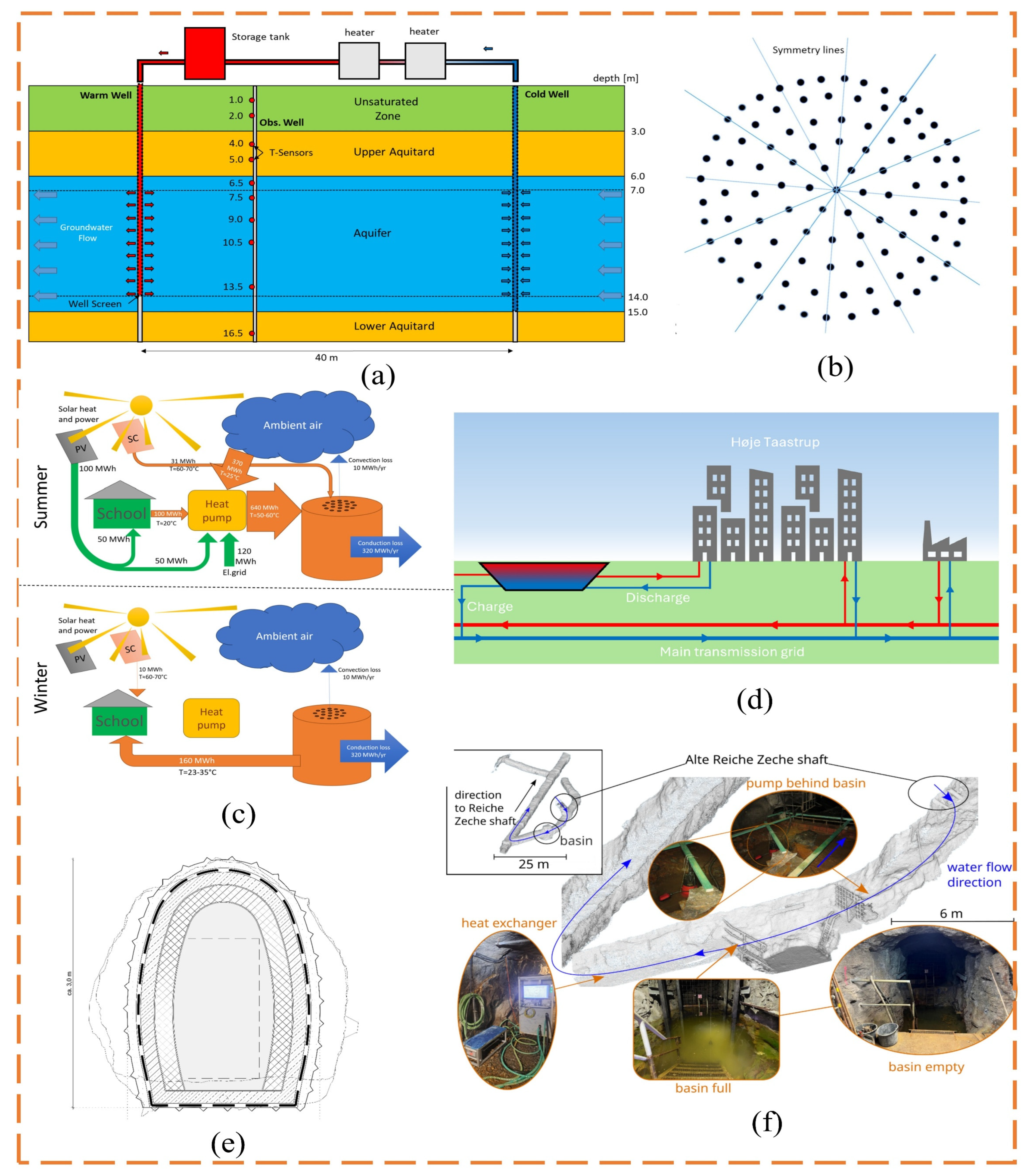
ATES and BTES both use natural subsurface media, but their heat-transfer mechanisms differ substantially. ATES generally employs paired cold and hot wells. During charging, groundwater extracted from the cold well is heated and injected into the hot well; the flow direction is reversed during discharging. Heat is transported principally by groundwater flow, making ATES suitable for permeable aquifers with low natural groundwater velocities and stable confining layers [74]. In high-temperature ATES cycling tests in a shallow sandy aquifer, Nordbeck et al. [44] found that thermal buoyancy displaced hot water toward the upper aquifer, increasing heat loss to the overlying aquitard (Figure 8a). Recovery efficiency decreased with storage duration, and unrecovered heat migrated downstream with the natural groundwater flow. BTES, by contrast, exchanges heat with the surrounding soil or rock through closed-loop pipes installed in boreholes without directly extracting groundwater. It is therefore less dependent on hydrogeological conditions, although heat-transfer rates are generally lower than those of ATES. BTES is particularly suitable where the ground has favorable thermal conductivity but aquifer conditions are inadequate. Kvalsvik et al. [75] examined a high-temperature BTES field comprising 100 boreholes and showed that a thermal barrier formed by 36 peripheral boreholes increased the stored heat after three years by approximately 20% and raised the mean reservoir temperature by approximately 2.5 °C (Figure 8b,c). The economic viability of the thermal barrier nevertheless depends on local construction costs and energy prices.
Clearly bounded storage facilities can also be created by excavating or constructing underground spaces. PTES uses a large excavated pit at or near the ground surface, equipped with an impermeable liner, insulated cover, and stratified inlet/outlet system, to store large quantities of sensible heat in water. During charging and discharging, water at different temperatures enters and exits through diffusers positioned at the top, middle, or bottom to maintain stratification. PTES is therefore suitable for sites with sufficient land, stable foundations, and proximity to district-heating networks [76]. Sifnaios and Jensen [45] analyzed a large PTES facility and reported annual energy and exergy efficiencies of 89% and 75%, respectively (Figure 8d). A single-plate diffuser installed at one side of the pit did not substantially disrupt stratification, although short-cycle high-temperature operation requires liners capable of long-term service at approximately 90 °C. Where surface space is constrained, CTES can be constructed in stable rock. Support, thermal-insulation, and sealing layers convert the cavern into a pressurized hot-water reservoir. Villeneuve et al. [77] proposed a crystalline-rock cavern with a maximum storage temperature of approximately 130 °C and pressure of approximately 8 bar (Figure 8e). Above 80–90 °C, conventional polymer sealing membranes became unsuitable, so a steel liner had to be considered. Increasing insulation thickness reduced rock heating and heat loss but raised construction cost.
Abandoned mines provide existing underground spaces that can be repurposed for thermal storage. MTES uses mine galleries, goafs, or shafts to store hot water; mine water transports heat, and the surrounding rock mass provides long-term storage capacity. It is applicable where the mine structure remains intact, water flow can be controlled, and heat users are nearby. Arab et al. [42] conducted three charge–discharge cycles at a depth of 147 m and found that approximately 90% of the heat was stored in the surrounding gneiss, while mine water primarily served as a rapid heat-transfer medium (Figure 8f). Through-flowing groundwater was the dominant source of heat loss, and iron-oxide deposition degraded heat-exchanger performance. Engineering applications of MTES must therefore control groundwater flow and address water quality, oxygen ingress, and heat-exchanger fouling.
Figure 8.
Five underground TES technologies: (a) ATES system [44]; (b) the boreholes in the built HT-BTES [75]; (c) heat flows to and from the HT-BTES (orange cylinder) during winter and summer [75]; (d) the PTES connection to the main transmission and local distribution grid [45]; (e) cavern liner, sealing layer, insulation, and surrounding rock [77]; and (f) Reiche Zeche MTES pilot layout [42].
ATES provides high heat-transfer capacity but is sensitive to aquifer architecture and groundwater flow. BTES offers stable operation and broad applicability but requires numerous boreholes and a long thermal response time. PTES provides large capacity at relatively low cost but is constrained by land availability and liner materials. CTES enables compact, high-temperature storage but imposes stringent requirements on rock stability, sealing, and insulation. MTES can reuse abandoned underground infrastructure, although performance depends on mine-water flow and hydrochemistry. These technologies provide alternative underground hosts for the geothermal–TES configurations discussed below. Selection should jointly consider geological conditions, storage temperature, duration, system scale, and the distances to both the heat source and thermal load.
3. Shallow Geothermal Energy Coupled with TES
3.1. Shallow Geothermal Systems and Their Storage Requirements
Shallow geothermal systems use relatively stable, low-grade heat in soil, rock, and groundwater and employ heat pumps to provide building heating and cooling [78]. According to the ground-side heat-exchange method, these systems are classified as closed-loop ground-coupled heat pumps or open-loop groundwater-source heat pumps. Energy piles extend the closed-loop concept by integrating heat-exchange functions into structural foundation piles to form energy geostructures [79].
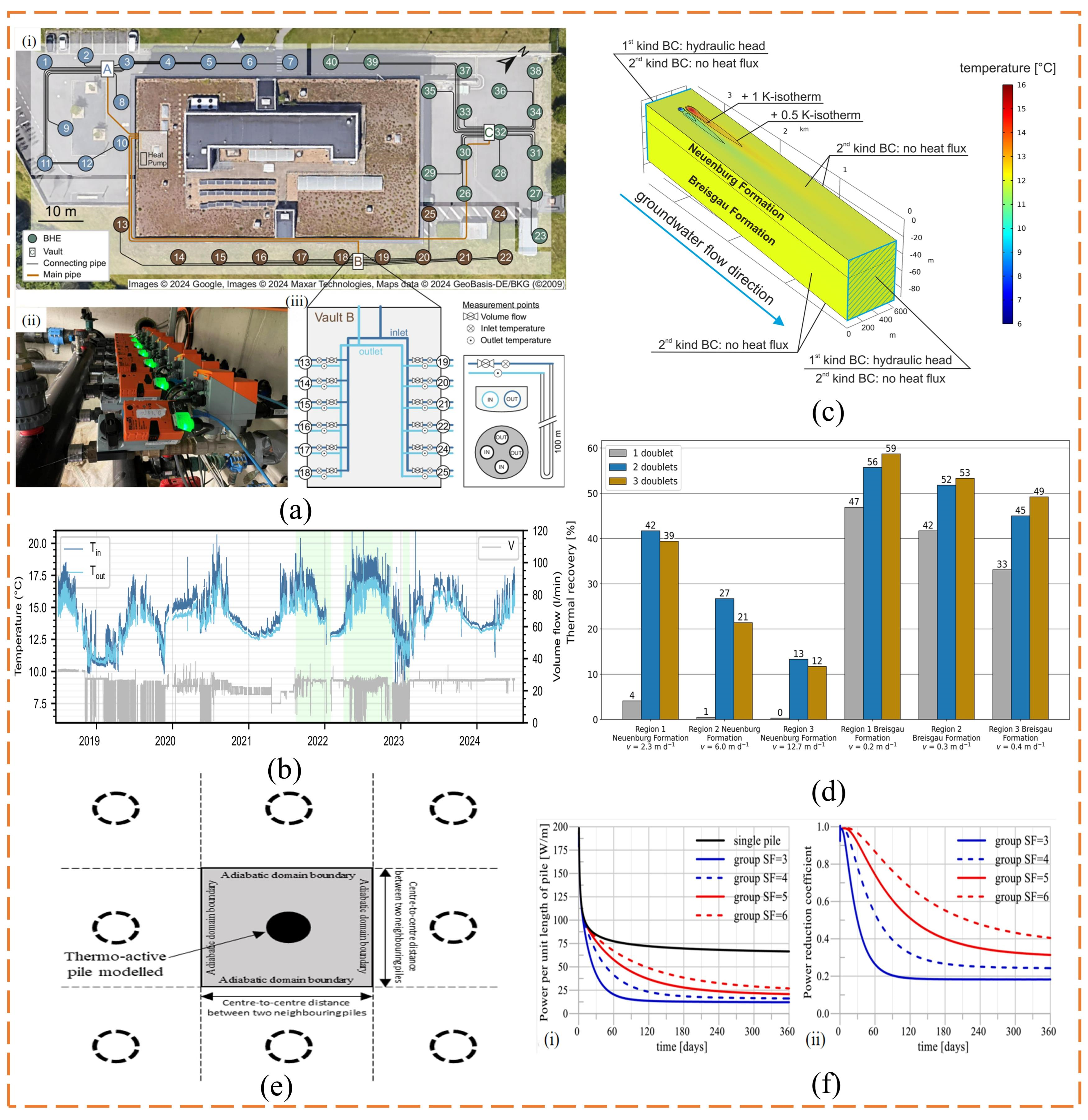
Ground-coupled heat pumps exchange heat between a circulating fluid in closed buried pipes and the surrounding ground. They do not extract groundwater, they adapt well to different sites, and they operate reliably; their main limitations are thermal interference among boreholes and long-term imbalance between heating and cooling loads [80]. Soltan Mohammadi et al. [81] developed a dynamic optimization method for borehole fields that accounts for transient groundwater flow. Monthly adjustment of the heat-exchange load assigned to each borehole reduced subsurface temperature variation by approximately 10%, indicating that zonal control can mitigate local heat accumulation. Piipponen et al. [82] simulated single boreholes and borehole fields of different depths in Estonia and found that groundwater velocities above 0.03 m·d−1 increased heat output by 3–20%, although formation temperature and thermal conductivity remained more influential. Heim et al. [83] published six years of operational data from a full-scale system comprising forty 100 m boreholes, including inlet and outlet temperatures and flow rates for each borehole, thereby providing a basis for long-term performance analysis and validation of storage-control models (Figure 9a,b). Collectively, these studies show that the ground surrounding a borehole functions as both a heat-exchange medium and a seasonal store. Injecting heat in summer, extracting it in winter, and adding short-term storage for peak-load reduction can limit ground-temperature drift and improve system stability.
Groundwater-source heat pumps extract water through production wells, exchange heat at the surface, and reinject the water into the aquifer. When heat is stored in groundwater during the cooling season and recovered during the heating season, the system becomes an ATES configuration. Stemmle et al. [84] developed an urban-scale ATES model and found that higher groundwater velocities removed part of the stored heat (Figure 9c,d). After optimization of doublet placement, however, recovery efficiency in the deeper aquifer reached 59%, and approximately 92% of the total cooling demand of residential buildings in the study area could be met. Sezer et al. [85] numerically simulated a groundwater-source heat pump and found that the thermal plume generated by reinjected cold water extended approximately 50 m. With sufficient well spacing and a low hydraulic gradient, the plume did not appreciably affect pumping temperature or system performance. The storage capability of groundwater-source systems therefore depends mainly on aquifer permeability, groundwater velocity, production–injection well spacing, and seasonal energy balance. Appropriate control of injection/extraction temperatures and flow rates is essential for limiting advective heat loss.
Energy piles contain heat-exchange pipes within building foundation piles, enabling the piles to provide both structural support and geothermal heat exchange. They are particularly attractive for urban buildings with limited underground space and usually operate in groups, making thermal interference and long-term heat accumulation more pronounced [86]. Liu and Taborda [87] investigated thermal interference in energy-pile groups with different spacings (Figure 9e,f). After 360 d of continuous operation, the heat-exchange capacity of an individual pile in a dense group was only 20–40% of that of an isolated pile, demonstrating that pile spacing and operating duration must be included in system design. Liu et al. [88] compared continuous and intermittent operation of deep-buried-pipe energy piles under groundwater seepage. Intermittent operation increased system energy efficiency by approximately 7.7%, and seepage further reduced heat accumulation within the piles. Ma et al. [89] examined a solar-assisted energy-pile system under future climate conditions and found that model-predictive control increased the annual coefficient of performance by 4.8–7.5% relative to rule-based control. Energy piles thus act not only as heat exchangers but also as pathways for storing rejected building heat or solar heat in the surrounding soil. Intermittent operation, active charging, and predictive control can mitigate group interference and improve long-term efficiency. Unlike dedicated borehole fields, however, energy piles are constrained by foundation layout and site area and cannot readily be expanded. Natural storage in the surrounding soil alone is therefore unlikely to offset annual heating–cooling imbalance, necessitating coordination with external TES devices.
Figure 9.
System configurations and storage-related operating characteristics of three representative shallow-geothermal technologies: (a) ground heat exchanger group and monitoring system [83]; (b) long-term operating temperature and flow rate of ground heat exchangers [83]; (c) ATES system model [84]; (d) heat recovery rate under different well group configurations [84]; (e) energy pile and pile group model [87]; and (f) heat transfer performance degradation caused by thermal interference of pile groups [87].
The fundamental constraint on shallow geothermal systems is not whether heat can be exchanged over a short period, but whether building loads and the subsurface thermal environment can remain balanced over the long term. Short-term storage devices are suited to absorbing hourly peak loads, whereas soil and rock, aquifers, and the ground surrounding piles can provide seasonal storage. Combining these timescales reduces the design capacity of geothermal heat exchangers, limits ground-temperature drift, and converts a shallow geothermal installation from a single heat source into an adjustable building-scale heating, cooling, and storage system.
3.2. Ground-Source Heat Pumps Coupled with Short-Term TES
The energy-supply capacity of shallow geothermal systems is relatively stable, whereas building heating and cooling loads fluctuate markedly by the hour. Short-term mismatch can cause frequent heat-pump cycling, inefficient part-load operation, and higher peak electricity demand. Short-term TES is typically installed between the ground-source heat pump and building terminals, where it temporarily stores heat or cold produced by the heat pump and hydraulically and thermally decouples the source and load sides. According to the storage medium and operating objective, the main devices are buffer water tanks, chilled-water storage tanks, and latent-heat storage units [23].
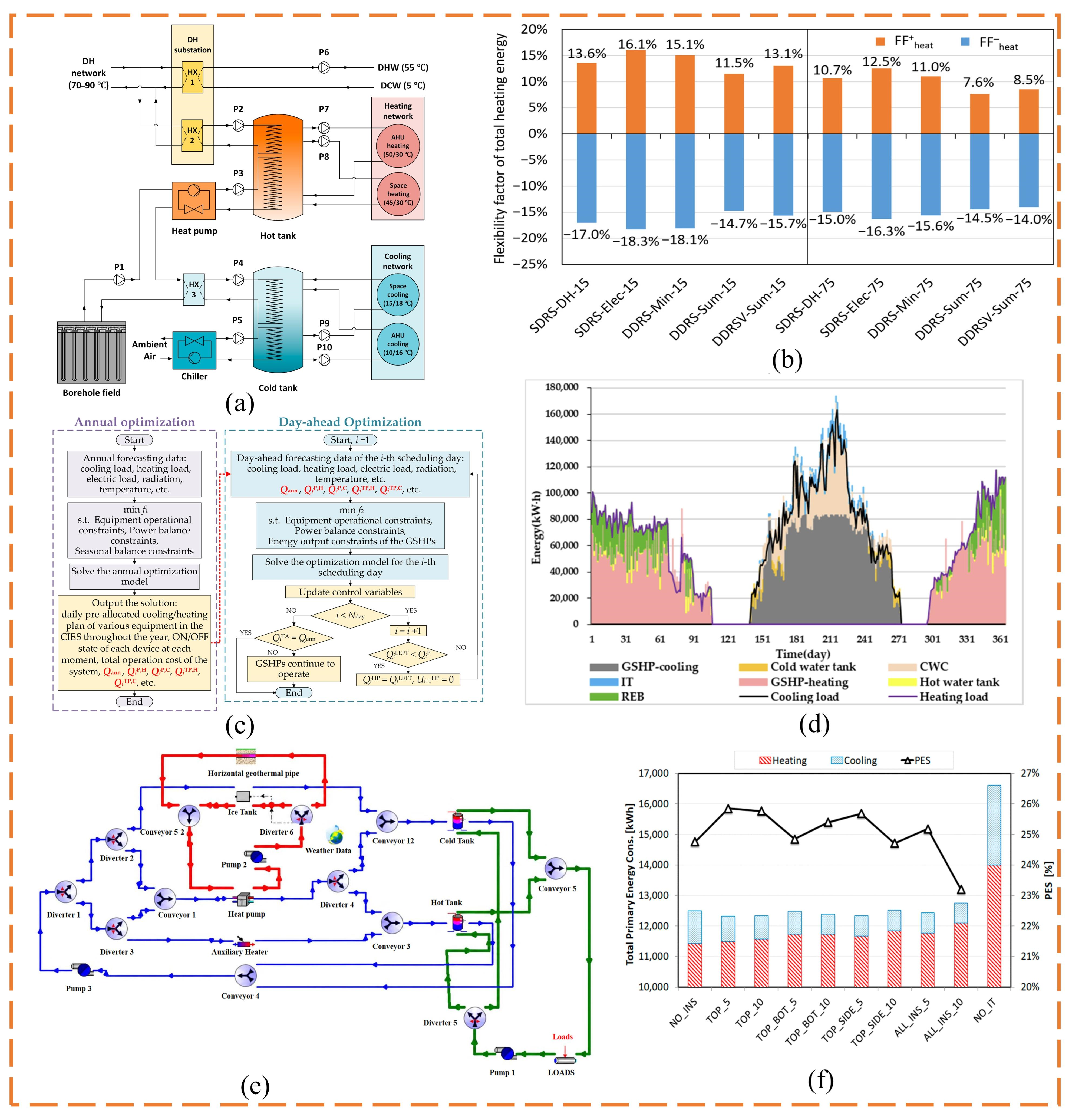
Buffer tanks use the sensible heat of water to absorb rapid load fluctuations. When building demand is lower than heat-pump output, surplus heat charges the tank; as demand rises, the tank and heat pump supply heat together, extending individual operating cycles and reducing start–stop frequency [90]. Tonellato et al. [91] developed a model-based continuous commissioning method for a groundwater-source heat-pump system with a buffer tank. Comparison of measurements with a baseline model identified control deviations among the tank, heat pump, and circulation pump. Although the tank improved stability, its effectiveness depended on coordinating temperature set points, flow regulation, and heat-pump cycling. Xue et al. [92] investigated demand response in a hybrid ground-source heat-pump system incorporating a 5 m3 hot-water tank and a 3 m3 cold-water tank (Figure 10a,b). Combining storage with price-responsive control reduced annual operating costs by up to 10.8% while maintaining indoor thermal comfort. In a survey of 605 ground-source heat-pump retrofit projects, Kallioharju et al. [93] found that buffer capacities of 500–1000 L were common, with a weighted average of approximately 774 L. Tank size should therefore be determined from heat-pump capacity, the water volume of the building system, and the permissible cycling interval.
Chilled-water tanks store cold water produced by a ground-source heat pump during low-load or low-price periods and discharge it during periods of high daytime demand. Compared with ordinary buffer tanks, they generally provide a longer storage period, larger temperature difference, and greater capacity; their main functions are to shift cooling demand and reduce heat-pump power during peak periods. Liu et al. [94] investigated a community integrated energy system in which ground-source heat pumps cooperate with a cold-water tank during the cooling period (Figure 10c,d). Under the proposed scheduling strategy, the cold-water tank participates in cooling-load allocation and supports the seasonally balanced operation of the GSHP system. Xue et al. [95] performed long-term simulations of a system with a 5 m3 hot-water tank and a 3 m3 cold-water tank. Raising the chilled-water temperature supplied to the air-conditioning terminals and optimizing operating parameters reduced the subsurface thermal-imbalance ratio by 12 percentage points and increased the minimum borehole outlet temperature by approximately 3 °C. Kim et al. [96] incorporated chilled-buffer-tank temperature into centralized ground-source heat-pump control. Field comparison tests showed that optimized control reduced electricity consumption by 11.75% and operating cost by 13.27%. Cold-storage performance therefore depends not only on tank capacity but also on charging/discharging schedules and control strategy.
Latent-heat storage units use the heat of phase transition to achieve a higher energy density than water tanks in a smaller volume while maintaining a relatively stable supply-water temperature near the transition point. Ryu et al. [97] installed PCM capsules in the heat-recovery tank of a hybrid ground-source heat pump and maintained the heat-pump inlet above 5 °C. Combined with intermittent circulation-pump operation, the maximum power consumption of the heat pump and circulation pump decreased by 48.1% and 78.8%, respectively. Mancin and Noro [98] analyzed a reversible heat pump coupled with a ground ice-storage tank and ground heat exchangers for annual residential air conditioning in Milan (Figure 10e,f). During cooling, stored ice can supply free cooling without operating the heat pump when sufficient cold is available; otherwise, the heat pump and ground heat exchangers meet the residual load. For a 58.8 m3 store, a 5 cm top-insulation layer gave the best balance between winter heat extraction and summer free-cooling recovery. The study demonstrates how latent ground storage can shift seasonal loads while limiting the required ground-heat-exchanger capacity. Rae et al. [99] connected a PCM module directly to the refrigerant circuit of a ground-source heat pump. The module delayed compressor start-up by approximately 40 min to more than 2 h while maintaining essentially the same heating supply, demonstrating its advantage for short-term load shifting.
Buffer tanks are structurally simple and suitable for suppressing load fluctuations from minutes to hours. Chilled-water tanks offer greater capacity and are better suited to intra-day load shifting and time-of-use electricity-price management. Latent-heat storage offers high energy density and stable discharge temperature, although its cost, heat-transfer performance, and long-term cycling stability require further improvement. These devices primarily improve short-term ground-source heat-pump operation and cannot independently resolve seasonal subsurface heat imbalance.
Figure 10.
Coupling configurations and operating performance of ground-source heat pumps and typical short-term TES devices: (a) buffer water tank coupled system [92]; (b) flexibility coefficient of the total heating energy in the heating season [92]; (c) structure and energy flows of the GSHP subsystem coupled with a cold-water tank [94]; (d) load-power allocation under the proposed seasonally balanced scheduling strategy [94]; (e) reversible heat pump coupled with ground ice storage and ground heat exchangers [98]; and (f) annual energy-performance or storage-state result for the ground ice-storage system [98].
Short-cycle underground storage is included in this review when a borehole field is deliberately charged and discharged over a defined hourly-to-weekly cycle, rather than merely experiencing transient heat exchange during normal GSHP operation. Recent modeling shows that cycle duration changes the recovery factor and thermal interference of BTES, while medium-depth ground heat exchangers require an inlet temperature above a configuration-specific threshold before intentional charging improves later heat extraction [100,101]. This boundary prevents routine shallow-GSHP buffering from being conflated with controlled UTES, while recognizing that short-cycle BTES can complement surface tanks when land, drilling, and load profiles justify it.
3.3. Shallow Geothermal Energy Coupled with Seasonal Underground Thermal Energy Storage
Shallow geothermal systems commonly experience an annual timing mismatch between supply and demand: heat rejected by buildings in summer cannot be used immediately, whereas heat must be extracted continuously from the ground in winter. Seasonal underground storage establishes a recoverable subsurface temperature field across seasons, converting shallow formations from passive heat sources or sinks into cyclically rechargeable storage media. BTES exchanges heat with soil and rock through closed-loop pipes, whereas ATES directly extracts and reinjects groundwater; the two therefore differ substantially in operation and applicable geological conditions [73]. Their principal differences in operating characteristics and applicable geological conditions are summarized in Table 3.
Table 3.
Comparison of shallow BTES and ATES for seasonal TES.
A BTES field comprises multiple vertical borehole heat exchangers through which a circulating fluid injects heat into or extracts heat from the surrounding ground. In heating-dominated regions, heat is commonly stored underground in summer and recovered by a ground-source heat pump in winter. Where summer cooling loads are substantial, winter cold can also be stored and used in summer for direct cooling or to lower heat-pump condensing temperature [35,107]. Because the fluid does not contact groundwater directly, BTES imposes limited requirements on aquifer permeability; however, storage relies primarily on conduction and charging and discharging are comparatively slow [102]. Borehole number, depth, spacing, and arrangement jointly determine the temperature field. Close spacing promotes a compact storage region, but excessive proximity increases thermal interference; wide spacing increases storage-surface area and heat loss [103]. A high volumetric heat capacity increases storage capacity, whereas high thermal conductivity accelerates charging and discharging but can also increase seasonal heat diffusion into surrounding formations [108]. Groundwater flow can displace the thermal plume and is generally detrimental when the objective is to preserve a temperature anomaly [109].
Miceli et al. [110] developed a g-function model incorporating borehole connections, initial ground temperature, thermophysical properties, and top-surface insulation (Figure 11a,b). The predicted seasonal efficiency of the Palermo demonstration system was approximately 70%, and improved top insulation increased storage temperature by approximately 3.5–4 °C. Zhao et al. [111] validated a rapid temperature-prediction method using data from a full-scale field of 2000 boreholes, each 150 m deep; the error in mean storage temperature was below 1.2%, indicating that reduced-order models can support long-term analysis of large BTES fields. Carlsson [112] developed a coarse-grained radial model of a cylindrical borehole array and used it to optimize extraction strategy and storage geometry (Figure 11c,d). A modified extraction strategy increased the capacity by 25% for a system with a 20% smaller radius, while doubling the borehole density increased capacity by 29%, illustrating the trade-off between compact layout and recoverable heat. Chicco and Mandrone [113] modeled BTES charging and the first 30 days of heat extraction (Figure 11e). The simulated store delivered approximately 476,000 kWh during the first month and could support base, peak, and backup heating loads, showing how numerical models can translate subsurface temperature evolution into an operating plan. Asan et al. [109] found that Darcy velocities below 0.3 m per month had little effect, whereas performance declined substantially above this value. Repositioning boreholes and adding downstream boreholes mitigated advective heat migration (Figure 11f,g).
Figure 11.
Studies of seasonal BTES: (a) contour plot of the BTES temperature [110]; (b) g-function response under different surface adiabatic boundary conditions [110]; (c) cylindrical borehole-array model used for coarse-grained BTES analysis [112]; (d) capacity response to extraction strategy or borehole density [112]; (e) Inner (Tin, °C) and outlet (Tout, °C) temperatures over 30 days of operation [113]; (f) boundary and initial conditions of the VHT-BTES field [109]; and (g) prediction of the 2D model for variation in SCOP with Darcy velocity [109].
ATES commonly uses one warm and one cold well to transfer heat and cold seasonally through groundwater extraction, heat exchange, and reinjection. In summer, cold groundwater is extracted for cooling and, after absorbing building heat, is reinjected into the warm well, thereby storing heat. In winter, water is extracted from the warm well, heat is recovered by a heat pump, and cooled water is reinjected into the cold well, simultaneously storing cold [114]. ATES can thus provide seasonal heat and cold storage within the same annual cycle. Performance is governed principally by aquifer thickness, porosity, permeability, groundwater velocity, thermal dispersion, and well spacing [115]. The aquifer must provide adequate transmissivity for stable flow, while warm and cold wells must be separated sufficiently to prevent plume interference [116]. Strong natural groundwater flow displaces stored water downstream and reduces recovery temperature and efficiency [117]. Thermal conductivity, mechanical dispersion, and aquifer heterogeneity jointly shape the plume, making site-specific hydrogeological investigation more important for ATES than for BTES.
Tang and Rijnaarts [118] developed a dimensionless framework applicable to different plume geometries and operating cycles, showing that ATES recovery efficiency is jointly controlled by aquifer conduction, mechanical dispersion, and plume geometry; the efficiency of a cylindrical plume does not simply increase with porosity or heat capacity [104]. Chen et al. [119] developed a machine-learning-assisted g-function model for bidirectional seasonal operation that accounts for heat exchange with confining layers while accelerating long-term temperature prediction. Todorov et al. [106] modeled an ATES system integrated with district heating and cooling in a Finnish urban district (Figure 12a,b). Adding a precooling heat exchanger increased the fractions of heating and cooling demand covered by ATES by 13% and 15%, respectively, and reduced energy-production cost by 5.2%. Balanced annual operation also limited the modeled long-term environmental impact, demonstrating the importance of matching seasonal injection and extraction. Tas et al. [105] performed global sensitivity analyses for a thick sandy aquifer and a shallow alluvial aquifer and identified natural hydraulic gradient, permeability, and their combined Darcy flux as the dominant controls on recovery efficiency (Figure 12c,d). Larger storage volumes and low-permeability layers reduced plume migration. Lepinay and Woods [104] studied long-term cycling in a low-temperature ATES doublet and found that whether operation begins in summer or winter influences outlet temperature over the first 5–10 cycles (Figure 12e,f). Beginning with summer cooling reduced the 20-year mean electricity consumption for heating by approximately 9.9%.
Figure 12.
Studies of seasonal ATES: (a) general integration of ATES with district heating and cooling [106]; (b) annual district-network temperature or energy-flow response for the integrated ATES case [106]; (c) shallow alluvial aquifer model and the layout of cold and hot wells [105]; (d) relationship between Darcy flux and heat recovery efficiency in shallow aquifers [105]; (e) schematic of an ATES providing space heating in the winter and a ground-source heat pump system or borehole [104]; and (f) average power-saving rate of heat pumps under different initial operating seasons (the shaded area denotes the root mean square error of the COP data) [104].
UTES design is governed mainly by ground conditions, peak-load characteristics, and the storage mechanism. Ground thermal conductivity and borehole thermal resistance determine the charging and discharging rates as well as the required number and spacing of borehole heat exchangers. In contrast, groundwater advection and large-scale thermosiphon circulation can transport heat beyond the storage boundary and substantially reduce seasonal recovery. Compact BTES arrays with a low surface-area-to-volume ratio and an insulated upper boundary are therefore preferable, particularly for high-temperature storage [120]. The load profile determines both the seasonal storage capacity and the required discharge power. BTES is generally more suitable for managing seasonal energy imbalance than for supplying short-duration peak loads because heat transfer through the ground is comparatively slow. Where sharp hourly peaks occur, BTES can be combined with a surface water tank or PCM unit so that the underground store supplies seasonal capacity while the surface store provides rapid response. The storage mechanism also determines the geological requirements and dominant loss processes. BTES is mainly conduction-controlled and can be applied where no productive aquifer is available, whereas ATES relies on groundwater extraction and reinjection and therefore requires adequate aquifer permeability, acceptable water quality, and control of thermal-plume migration. UTES design should consequently match geology, seasonal energy demand, peak power, and response time rather than being based on storage capacity alone.
Nordic experience broadens the evidence base beyond individual simulations. Swedish BTES development, including the Anneberg residential project, demonstrates both the feasibility of seasonal rock storage and the importance of array geometry, top insulation, and multi-year thermal conditioning [121]. A review led by Norwegian and UK researchers shows that groundwater advection, thermosiphon circulation, and a high surface-area-to-volume ratio can prevent high recovery even when borehole heat transfer is locally strong; it therefore recommends compact arrays and pairing seasonal BTES with faster surface stores [120]. ATES deployment is concentrated in northwestern Europe, with Sweden and Denmark among the principal markets outside the Netherlands, and typical reported payback periods of 2–10 years remain strongly dependent on scale and utilization [122]. These cases indicate that cold climates alone do not guarantee feasibility: district-network temperature, summer charging heat, annual balance, and local hydrogeology determine whether seasonal storage creates useful value.
For seasonal stores, first-cycle recovery should not be equated with stable long-term performance. Where data permit, this review interprets results using cycle-resolved recovery (Qout,n/Qin,n), delivered-temperature drift, retained energy after standby, and cumulative thermal imbalance. For ATES, Darcy flux and the thermal Peclet number, Pe = vL/α, indicate whether plume transport is conduction- or advection-dominated; because characteristic length and velocity definitions differ among studies, no universal Pe acceptance threshold is imposed here.
Overall, BTES is suitable where groundwater conditions are uncertain or aquifer permeability is low; its key design variables are borehole arrangement, ground thermophysical properties, and zonal operation. ATES charges and discharges more rapidly and can achieve high heat and cold recovery but imposes stricter requirements on aquifer permeability, groundwater-flow direction, and water quality. Both technologies should pursue annual energy balance by coordinating summer heat storage with winter heat extraction and winter cold storage with summer cold recovery, thereby avoiding persistent unidirectional subsurface temperature change.
3.4. Solar–Shallow Geothermal–TES Systems
Solar energy exhibits strong diurnal and seasonal variability, whereas shallow geothermal energy provides a comparatively stable low-grade heat source. Combining both with TES can increase solar utilization while mitigating subsurface thermal imbalance [123]. According to the form of solar conversion and the coupling pathway with the ground-source heat pump and storage unit, solar–GSHP–TES systems can be divided into solar-thermal, photovoltaic-driven, and photovoltaic/thermal (PVT) configurations. Solar-thermal systems supply heat, photovoltaic systems primarily power the heat pump and auxiliaries, and PVT systems simultaneously provide electricity and low-temperature heat [124].
Recent studies have focused on system configuration, subsurface heat balance, and storage-control strategies. At the building-system level, Huang et al. [125] reviewed active and passive applications combining solar thermal utilization with heat storage and identified storage-material optimization, heat-transfer enhancement, intelligent control, and system integration as the principal directions for improving energy efficiency and solar-energy utilization. Yu et al. [126] used dynamic simulation to compare three solar-assisted ground-source heat-pump arrangements (Figure 13a). In the configuration with a 300 L solar-side storage tank, the average heat-source temperature reached 14.81 °C, and the heat-pump and system COPs were 5.23 and 4.32, respectively; a Winnipeg case still achieved a COP of 4.51, indicating that solar storage can improve GSHP performance in cold climates with sufficient solar availability. Sazon et al. [127] compared three arrangements in which solar collectors and borehole heat exchangers were connected in different series orders or in parallel (Figure 13b). Considering overall energy efficiency, heating cost, and subsurface temperature change, the series configuration with the collector upstream of the borehole performed favorably; total borehole length was the dominant parameter. Cao et al. [128] developed a solar-assisted GSHP in which solar energy supplied part of winter heating and year-round domestic hot water, while residual heat in a water tank was injected underground during the non-heating season (Figure 13c,d). Long-term simulations showed that appropriate collector area and borehole-field size reduced energy use and ground-temperature decline. PVT systems can improve both electrical supply to the heat pump and subsurface source conditions. Focusing on storage-side enhancement in solar heating systems, Li et al. [129] combined rotational operation with radial-gradient metal foams to strengthen both heat conduction and natural convection. The optimized four-layer configuration reduced the heat-storage time by 18.35% and increased the heat-storage rate by 23.01% compared with a rotating tank filled with uniform metal foam. Liravi et al. [130] found that PVT heat replenishment reduced total borehole length by up to approximately 50% and initial investment by 9.32% and 22.92% in two configurations while maintaining comparable seasonal performance and stable ground temperature. Pourier et al. [131] investigated a system combining PVT, a GSHP, and free cooling (Figure 13e,f). A configuration with 96 PVT modules and four boreholes achieved seasonal performance comparable to that of a six-borehole system while reducing land use by approximately 50%; additional PVT capacity also reduced subsurface thermal imbalance. Coupling photovoltaics with TES centers on using surplus electricity to drive the heat pump during charging. Ocłoń et al. [132] investigated a heating system combining PVT panels, solar collectors, a heat pump, and two underground water-storage tanks (Figure 13g). Solar heat was stored in the tanks and surrounding ground for later heating use. Numerical optimization showed that underground storage could cover approximately 93% of the thermal energy demand in the studied case, with annual tank-temperature variations as shown in Figure 13h. Tong et al. [133] combined solar collectors, a water tank, a GSHP, and underground heat exchangers, using the tank for short-term regulation and the ground for seasonal storage. Annual heat extraction and rejection were nearly balanced, and mean soil temperature returned to approximately 17.8 °C after a complete cooling–heating cycle.
Figure 13.
Representative coupling configurations of solar–shallow-geothermal–TES systems: (a) solar-assisted GSHP configuration with a solar-side storage tank [126]; (b) parallel single-pipe/borehole heat exchanger [127]; (c) SAGSHP system schematic diagram [128]; (d) ground temperature attenuation trend [128]; (e) conceptual diagram of a PVT + GSHP [131]; (f) parametric study of MS system varying borehole count and spacing [131]; (g) schematic of the solar-assisted heat pump system with underground thermal storage [132]; and (h) annual temperature variations of the underground storage tanks and outdoor air [132].
In solar–shallow-geothermal systems, TES does more than add a storage device: it creates a temporal buffer among solar supply, building demand, and ground heat exchange. Design should prioritize direct use of solar heat to meet demand and store only the surplus in water tanks or underground. For photovoltaic systems, heat-pump charging should be controlled according to surplus electricity, storage temperature, and subsurface heat balance. Future optimization should match solar capacity, tank volume, and borehole-field size and use predictive control to coordinate direct heating, short-term storage, and seasonal ground regeneration.
4. Medium-Deep and Deep Geothermal Energy Coupled with TES
4.1. Utilization Pathways for Medium-Deep and Deep Geothermal Energy
Medium-deep and deep geothermal systems cannot be classified reliably by depth alone. The European literature often places middle-deep resources at approximately 400–1000 m, whereas other regional schemes use broader intervals; temperature, formation type, heat-transfer mechanism, and well productivity are more transferable descriptors [16]. The utilization pathways considered here include open-loop hydrothermal production–reinjection doublets, closed-loop downhole heat exchangers, and enhanced geothermal systems. Open-loop systems can deliver high thermal power where transmissivity and reinjection are favorable, but scaling, corrosion, pumping, and thermal breakthrough affect both operation and TES integration. Closed-loop systems isolate the circulating fluid from the formation and avoid direct groundwater production, but their output is constrained by conduction and internal hydraulic losses. At 800 m and 5 L/s, a comparative study reported specific heat extraction rates of 39.1, 32.8, and 36.0 W/m for coaxial, single U-tube, and double U-tube exchangers, respectively, with markedly different pressure losses [17].
Natural hydrothermal geothermal energy mainly utilizes hot water or steam in deep aquifers. Geothermal fluids are extracted from production wells, release heat to the heating system in surface heat exchangers, and are then reinjected into the reservoir through injection wells. The production well and the injection well together form a geothermal well pair. This method can maintain reservoir pressure and reduce the direct discharge of geothermal water, and it is a common form of medium-deep geothermal heating. Drews et al. [134] found substantial spatial variations in production temperature and flow rate in a basin-scale hydrothermal heating project; together, these variables controlled heating capacity and economics. Gascuel et al. [135] compared three geothermal doublets and a downhole heat exchanger at depths of 1–2 km (Figure 14a,b). Where the reservoir had favorable permeability and productivity, doublets delivered greater thermal power but were more sensitive to reinjection capacity, fluid chemistry, and thermal breakthrough.
Closed-loop downhole heat-exchange systems do not extract geothermal fluid. A circulating fluid flows through coaxial or U-shaped pipes installed in a medium-deep borehole and exchanges heat with the surrounding rock through pipe walls, grout, or casing. Keeping geothermal fluid out of surface equipment avoids reinjection difficulties and reduces scaling and corrosion caused by highly mineralized water, making this approach suitable for low-permeability formations with favorable geothermal gradients. Subsurface heat transfer is primarily conductive, however, and outlet temperature and thermal output depend jointly on well depth, geothermal gradient, rock conductivity, wellbore design, insulation, and circulation rate [136]. Three-dimensional simulations by Lund [137] showed that pipe diameter, insulation, and flow rate can produce an approximately twofold difference in thermal output for a 2 km coaxial exchanger (Figure 14c,d). Excessive flow increases extracted heat but lowers outlet temperature and raises pumping demand.
Where natural reservoirs contain little fluid or have low permeability, hydraulic stimulation can create a fracture network to form an EGS. Cool fluid injected into engineered fractures absorbs heat from hot rock and returns through a production well. Compared with a closed-loop exchanger, EGS accesses a larger heat-transfer area but faces fracture short-circuiting, fluid loss, thermal breakthrough, and induced seismicity. Aljubran and Horne [138] showed that regulating wellhead flow and the power cycle can shift an EGS plant from steady baseload operation toward flexible generation, although frequent changes in subsurface circulation increase control complexity. Bu et al. [139] injected non-heating-season solar heat into low-permeability rock and recovered it during the heating season (Figure 14e,f). Continuous seasonal charging maintained stable operation over 20 years and achieved thermal recovery above 90%, indicating that rock surrounding engineered fractures can provide medium- to long-term storage.
High-temperature, high-enthalpy geothermal fluids can generate electricity through dry-steam, flash-steam, or organic Rankine cycles (ORCs). High-temperature steam is generally suited to direct or flash generation, whereas medium-temperature water can drive an ORC. Geothermal brine leaving the power plant can then supply district heating and domestic hot water in a cascade. Geothermal generation provides stable baseload electricity, but continuous thermal output does not necessarily coincide with grid demand. Ayadi et al. [140] coupled a geothermal source at approximately 140.7 °C with four Carnot-battery configurations (Figure 14g,h). The configuration using a flash heat pump for charging and an ORC for discharging achieved favorable heat-to-power conversion, with efficiency approximately 30% higher than the weakest configuration. Agson-Gani et al. [141] proposed a “geothermal battery” integrating the concentration of solar power, ultra-high-temperature underground storage, and geothermal generation. Long-term subsurface retention of high-temperature heat increased the mean thermal-energy gain of the geothermal–ORC system by approximately 70%.
TES requirements differ among utilization pathways. Hydrothermal doublets provide relatively stable heat while demand fluctuates; a hot-water tank between the surface heat exchanger and users can shave hourly to daily peaks, and surplus summer heat may be stored seasonally in an aquifer or deep reservoir. Downhole heat exchangers have limited short-term output flexibility and are better combined with buffer tanks or PCM units to stabilize flow, reduce heat-pump cycling, and cover short peaks. EGS can use both surface high-temperature storage and subsurface rock storage, but injection/production pressure and heat migration through fractures must be controlled. Geothermal power plants can use pressurized water, thermal oil, molten salt, solid packed beds, or Carnot batteries selected according to operating temperature to convert continuous geothermal heat into dispatchable electricity. Coupling should therefore reflect resource temperature and operating mode: direct heating must accommodate intra-day and seasonal demand, downhole exchangers require stable extraction and heat-pump operation, EGS must balance reservoir heat and safety, and power generation emphasizes high-temperature storage and grid regulation. TES does not replace the geothermal source; it translates stable geothermal output into flexible heat and power supply.
Figure 14.
Utilization pathways for medium-deep and deep geothermal energy and their TES coupling characteristics: (a) schematic figure of the three types of doublets and coaxial DBHE modeled [135]; (b) maximum heating power that could be supplied to consumers using heat pump [135]; (c) principle of deep borehole heat exchanger heating system [137]; (d) effect of mass flow rate on the heat pump and system COP [137]; (e) system diagram of the hybrid heating system of SDEGS and solar energy [139]; (f) EGS injection/production temperatures, thermal power, and recovery efficiency [139]; (g) schematic diagram and structure of the Carnot battery under the Config-1 configuration [140]; and (h) comparison of the thermodynamic performances of the configurations with and without geothermal source integration [140].
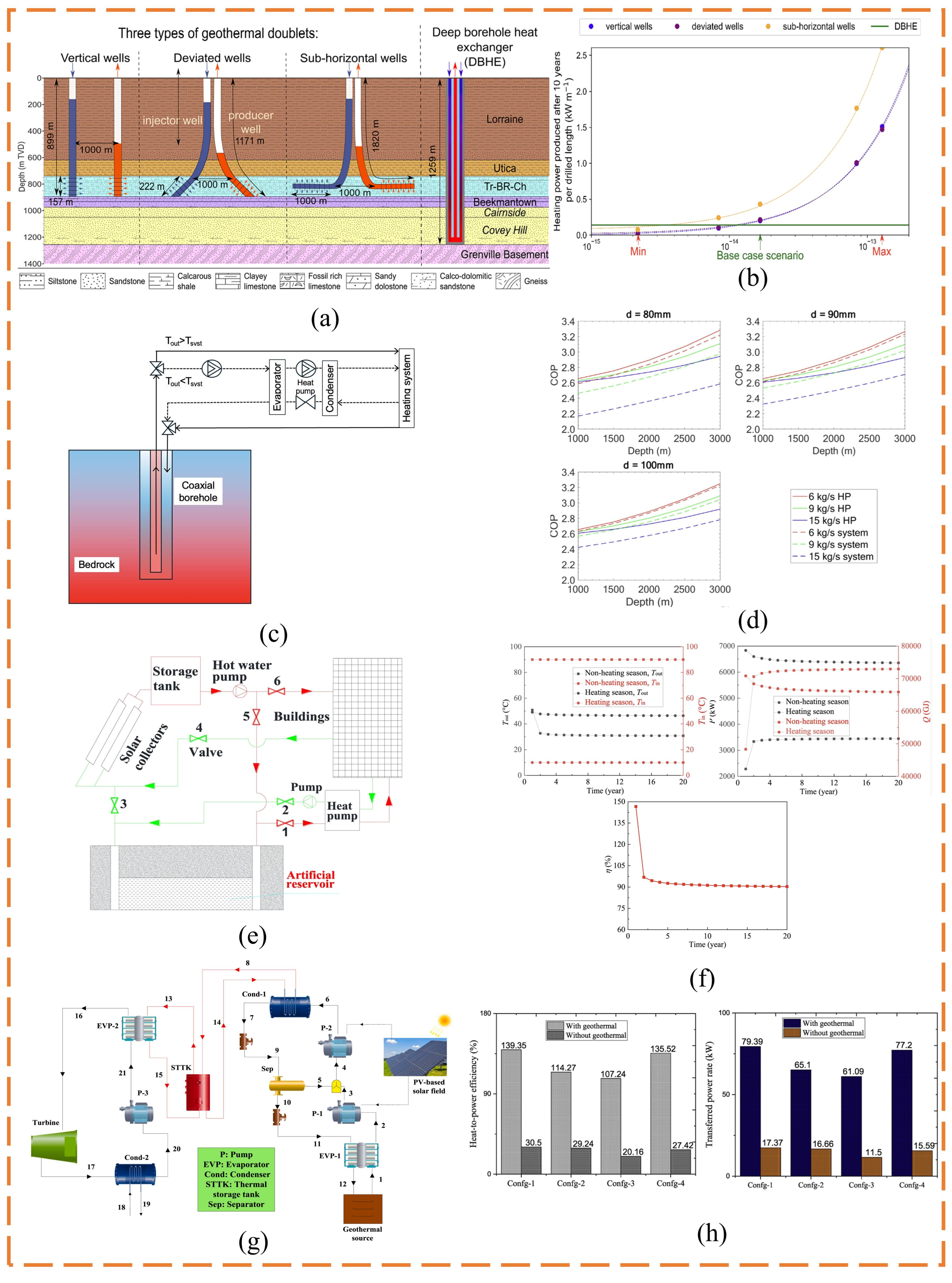
4.2. Medium-Deep Geothermal Heating Coupled with Short-Term TES
Medium-deep geothermal systems provide a comparatively stable heat source, whereas building demand varies hourly with outdoor temperature and user behavior. Short-term water storage can be installed in the clean-water loop of a geothermal heat-pump heating system to mitigate this mismatch. During low-load periods, the geothermal heat pump operates steadily and charges the tank; during high-load periods, the tank discharges in parallel with the heat pump, limiting large equipment adjustments between peak and off-peak conditions [142]. Water tanks, typically installed downstream of the heat pump or within the secondary network, are a mature option and use water temperature and stratification for hourly storage [143]. Zhu et al. [144] optimized a medium-deep GSHP–tank system, reducing heating cost by 12.82% and increasing system COP and the medium-deep geothermal utilization factor by 10.35% and 1.96%, respectively (Figure 15a,b). Zhang et al. [145] optimized a hybrid solar–wind–water-tank–medium-deep-GSHP system and obtained a tank volume of 152 m3; storage and heat replenishment prevented the 13.1% soil-temperature decline predicted for the conventional system after 20 years (Figure 15c,d). Moustakidis et al. [146] evaluated a district-heating plant incorporating a 100 m3 stratified water tank. Optimized TES operation reduced the use of the gas boiler when stored heat was available and lowered the 14-day net operating cost from EUR 5997.93 to EUR 4908.50, corresponding to a reduction of approximately 18% (Figure 15e). Jodeiri et al. [49] reduced simulation time for a stratified tank by 55% using an adaptive mesh at comparable uncertainty, supporting real-time control (Figure 15f). Xing et al. [147] experimentally and numerically investigated thermal stratification in a hot-water storage tank (Figure 15g,h). The hot-water output rate was 84.90% for an elbow-type inlet, compared with 76.39% for a water-distributor-type inlet, highlighting the importance of inlet design in maintaining stratification during discharge.
Figure 15.
Short-term water-tank storage in medium-deep geothermal heating: (a) medium-deep GSHP–tank configuration [144]; (b) evolutions in heat storage after optimization [144]; (c) solar–wind–tank–medium-deep-GSHP system [145]; (d) comparison of annual average soil temperature and attenuation rate between the MDGSHP system and the SA-MDGSHP system over 20 years of operation [145]; (e) optimal heat production and load distribution in a district-heating system incorporating a 100 m3 stratified water-storage tank [146]; (f) enhanced adaptive-grid model featuring two additional nodes positioned below and above the ports [49]; (g) arrangement of six temperature measurement points in the hot-water storage tank [147]; and (h) comparison of measured and simulated tank temperatures at different heights during discharge [147].
When medium-deep geothermal fluid is relatively hot or a high-temperature heat pump is used to raise supply temperature, pressurized hot-water tanks can provide short-term storage [148]. Elevated pressure keeps water liquid above 100 °C, broadening the sensible-storage range and increasing volumetric energy density. During low demand, the geothermal well or high-temperature heat pump charges the tank; during a short demand peak, the tank discharges rapidly so that well flow and output remain stable. Pressurization nevertheless increases requirements for vessel strength, safety protection, insulation, and control of geothermal-fluid corrosion and scaling. Staub et al. [149] developed a storage system comprising a reversible heat pump, an ORC, and a high-temperature water tank, using approximately 90 °C as a representative geothermal-source temperature (Figure 16a,b). The heat pump upgraded low-grade geothermal heat for storage in hot water; round-trip efficiency depended mainly on storage temperature, heat-pump performance, and expander efficiency, with a theoretical maximum of 69.6% for a two-stage cycle. Boysen et al. [150] modeled a stable-temperature geothermal source, heat pump, and pressurized-water store in district-heating optimization (Figure 16c,d). Dispatch results for constant and dynamic supply temperatures generally differed by less than 1% unless the heat-pump temperature limit was approached, demonstrating the need to coordinate source temperature, heat-pump outlet temperature, and storage state. Scharrer et al. [151] further studied a deep-geothermal heat-pump/pressurized-water/ORC system. Geothermal fluid at 85 °C was upgraded and stored at approximately 121 °C; the calculated heat-pump COP, ORC efficiency, and round-trip efficiency were 4.88, 10.25%, and approximately 50%, respectively. A 30 °C storage temperature difference required about 28.5 m3 of water and 1 MWh of heat. Life-cycle assessment identified tank steel and insulation as the main manufacturing impacts, although with wind-powered charging, the system performed environmentally better than the compared lithium-ion and lead-acid batteries.
Figure 16.
Pressurized hot-water storage in medium-deep geothermal systems: (a) heat-pump charging and ORC discharging configuration [149]; (b) effect of storage temperature on round-trip efficiency [149]; (c) district-heating optimization model and input–output relationships [150]; and (d) equipment load-duration curves at different supply temperatures [150].
PCM storage can be installed between the geothermal well, geothermal heat pump, and user. It absorbs surplus heat at low load and releases latent heat at a nearly constant temperature during peaks, allowing the well to operate relatively steadily. Compared with water tanks, PCM storage offers higher volumetric energy density and smaller discharge-temperature variation, but performance depends on matching the transition temperature to geothermal supply and return temperatures and on material conductivity, heat-exchanger design, stratification, and cycling stability. Liu et al. [152] developed a cascade composite-PCM roadway heat-exchange system for high-temperature hazards in deep mines (Figure 17a,b). With an annular-tube radius ratio of 2:3, the solid fraction reached 89.03%, and the mean monitored temperature decreased by 9.54 °C; a transition temperature of 25 °C and cascade-tube spacing of 0.5 m provided favorable combined performance. Coelho et al. [153] coupled boreholes and a GSHP with multiple PCM tanks in a residential demonstration (Figure 17c,d). Measured capacities for heating, cooling, and domestic-hot-water units were 21.9, 14.5, and 6.2 kWh, enabling 44.8% of heating demand and 30.3% of cooling demand to be shifted. Although based on shallow geothermal energy, the stable-GSHP/variable-PCM-load concept informs medium-deep peak regulation. Nair et al. [154] developed a macroencapsulated PCM/expanded-graphite unit with multiple flow passes (Figure 17e,f). Capacity reached 12.6 MJ, maximum mean charging and discharging powers were 1440 and 1990 W, and 90% of the heat was released within 90 min. Raheem et al. [155] tested a hybrid water–PCM tank containing 54 kg of macroencapsulated paraffin (Figure 17g,h). Relative to a water-only tank, maximum stored and recovered heat increased by 30.5% and 68.8%. Higher flow accelerated charging and discharging but intensified fluid mixing and weakened stratification, requiring a trade-off between power and stratification. Using a different water–PCM configuration, Huang et al. [156] placed a water layer beneath paraffin to enhance contact heat transfer during solidification. Increasing the water-layer height to 5 and 10 mm shortened the solidification time by 46.57% and 66.67%, respectively, while the corresponding reductions in total released heat remained below 10%; a positive-gradient arrangement further increased the average heat-release rate. Iung et al. [157] studied PCM melting and solidification in an annulus outside a hot-water tank and identified optimal aspect ratios of 19.32 and 16.29 for melting and solidification; their heat-transfer correlation differed from numerical results by only 1–6%. Optimizing the annular geometry can therefore improve transfer without substantially increasing tank volume.
Figure 17.
PCM storage in medium-deep geothermal systems: (a) cascade composite-PCM roadway heat exchanger and numerical model [152]; (b) effects of annular-tube radius ratio on solid fraction and monitored temperature [152]; (c) hydraulic connection of a solar–GSHP–PCM-tank system [153]; (d) three consecutive summer days of system operation [153]; (e) physical model of a multi-pass macroencapsulated PCM/expanded-graphite unit [154]; (f) instantaneous charging power at different inlet temperatures and flow rates [154]; (g) PCM-cylinder arrangement and temperature-sensor locations in a water–PCM tank [155]; and (h) improvements in stored and recovered heat after adding PCM [155].
Atmospheric water tanks are mature and comparatively inexpensive for low-temperature geothermal peak regulation over periods from several hours to one day. Pressurized tanks extend the temperature range but add vessel, insulation, and safety costs. PCM units reduce volume and temperature swing where space is scarce, but their added material and heat-exchanger costs must be justified by avoided peak capacity or repeated price arbitrage. Across all three options, the well should carry a stable baseload while TES follows rapid fluctuations. The relevant economic comparison is not storage cost alone, but the annualized cost of the coupled system relative to avoided well capacity, auxiliary-boiler use, heat-pump cycling, and peak electricity charges.
4.3. Medium-Deep Geothermal Energy Coupled with Seasonal Thermal Energy Storage
Medium-deep geothermal resources can supply heat steadily over long periods, but their output is seasonally mismatched with building demand. Wells are underloaded or shut down during the non-heating season, whereas auxiliary sources must cover peaks during the heating season. Seasonal storage maintains well operation during the non-heating season; stores surplus geothermal heat in soil and rock, aquifers, or large water bodies; and recovers it in winter, thereby increasing annual well utilization and reducing fossil-fuel peaking.
In BTES, a medium-deep coaxial well can extract geothermal heat or, under reverse circulation, inject heat into the surrounding rock. Hot water is injected during the non-heating season to establish a high-temperature zone; during the heating season, a lower inlet temperature enables recovery of stored heat together with heat supplied by the geothermal gradient. Hirvijoki and Hirvonen [158] modeled seasonal charging and discharging in 2–4 km coaxial boreholes (Figure 18a,b). With well depth and mean power appropriately matched, a borehole could shift district-heating loads seasonally, and the calculated efficiency approached 100%, although this was an idealized numerical result. Brown et al. [159] converted an abandoned 920 m geothermal exploration well into a coaxial BTES (Figure 18c,d). Six months of charging increased end-of-season extraction power from approximately 54 to 69 kW, but the additional recovered heat was less than 20% of the injected heat, making economic viability dependent on inexpensive waste heat and existing well infrastructure. Krusemark et al. [160] reported a demonstration with three 750 m wells spaced 8.6 m apart. Expansion to 37 wells was projected to deliver 15 GWh·a−1 and 3.5 MW, with a recovery efficiency of 75% after five years. Medium-deep BTES has a small surface footprint and suits land-constrained sites, but deep drilling cost, internal thermal short-circuiting, and radial rock losses must be reduced. A more extensively studied cross-depth configuration transfers deep geothermal heat to shallow high-temperature ATES. A deep doublet, surface heat exchanger, and shallow aquifer wells operate together: in summer, continuously produced geothermal heat warms shallow groundwater before injection into the hot well; in winter, hot groundwater is produced for heating and reinjected at a lower temperature into a warm or cold well. Oerlemans et al. [161] used 92 °C heat from an approximately 2 km geothermal well to warm groundwater in an aquifer at 360–383 m to about 85 °C (Figure 18e). Maximum flow was 150 m3/h, and annual design storage was 27–28 GWh. At an average flow of approximately 86 m3/h, the temperature drop between the heat exchanger and reservoir was about 3.5 °C, corresponding to 4.8% heat loss; wellbore insulation and flow control therefore directly affect cross-depth storage. Using distributed-temperature-sensing data, Szklarz et al. [162] analyzed aquifer heat migration (Figure 18f,g). In the first summer, approximately 111,000 m3 of water at a mean temperature of 84.8 °C was injected, and approximately 83,000 m3 was recovered in winter, yielding 27% annual thermal recovery; recovery increased to 41% in the second year as the aquifer and surrounding rock were preheated. History matching with field temperatures reduced parameter uncertainty and improved predictions. Geerts et al. [163] found that adding high-temperature ATES to a geothermal-doublet district-heating system increased the renewable heat share by 9–18%, but the economics depended on matching well capacity, storage size, and winter demand (Figure 17h). High-temperature ATES must therefore be co-optimized with geothermal production, district load, and backup sources rather than designed independently.
Figure 18.
Seasonal storage coupled with medium-deep geothermal energy: (a) charging and extraction modes of a medium-deep coaxial borehole [158]; (b) effects of borehole depth and mean power on minimum supply temperature and storage efficiency [158]; (c) converted coaxial deep-well exchanger [159]; (d) wellbore-fluid temperatures during charging and extraction (the legend notes explain the time scales of the two plots) [159]; (e) relationship between flow rate and wellbore temperature loss [161]; (f) charging, standby, and recovery over two consecutive years in high-temperature ATES [162]; (g) processed distributed-temperature profiles over two cycles [162]; and (h) renewable-energy shares of different system configurations [163].
Medium-deep BTES is progressing from numerical studies to demonstration, while deep-geothermal/shallow-high-temperature-ATES systems already provide operational and long-term monitoring data. The latter most clearly embody cross-depth coupling: medium-deep extraction, shallow storage, and heating-season utilization. Future work should address compatibility between storage and network temperatures, subsurface plume migration, thermal breakthrough between wells, corrosion and scaling, and coordinated optimization of storage capacity and winter load.
4.4. Deep-Geothermal Power Generation and Cascade Thermal Storage
Deep geothermal resources provide relatively stable, high-temperature output suitable for flash, Kalina, and organic Rankine cycles. Their steady thermal production, however, does not fully match variable electricity, industrial-heat, and building-heat demand. TES placed between the well and power cycle, or on the waste-heat side of the cycle, can retain geothermal heat during low demand and release it during power or heat peaks, increasing flexibility while maintaining stable well operation.
In deep-geothermal power and cascade-heating systems, TES can be installed at the surface or implemented directly in the deep reservoir. Major et al. [164] modeled a sedimentary geothermal doublet at 2500–2550 m under Danish conditions and injected 90 °C water by reversing the doublet in summer (Figure 19a,b). Mean recovery was approximately 67%; extending storage from one to four months increased additional recovered heat from 2389 to 6667 MWh. After ten annual cycles, production temperature stabilized near 76.4 °C, approximately 1.5 °C above the initial value. Deep reservoirs can thus store surplus heat at low load and increase wellhead output during peaks, stabilizing the source for subsequent ORC generation, medium-temperature supply, and low-temperature building heating. Scapino et al. [165] allocated 125 °C geothermal heat from the Mol doublet in Belgium among an ORC, district heating, and adsorption storage (Figure 19c,d). Price- and load-responsive dispatch increased annual profit by approximately 41%, showing that TES can serve as an energy-scheduling unit in geothermal combined heat and power. For lower-temperature hydrothermal resources, a small ORC can be combined with hot-water buffering in a cascade. Operacz et al. [166] proposed a system for a 3572 m well in southern Poland in which geothermal water successively passed through an ORC, heating exchanger, and terminal users, with a buffer tank near 70 °C (Figure 19e). Storage retained surplus heat during low demand, supplemented peaks, reduced deep-well flow variation, and increased useful cooling of the geothermal water. Even where temperature is insufficient for large-scale generation, a “limited power–primary heating–low-temperature use” cascade can improve overall efficiency. TES should also be integrated with the multiple temperature levels of deep geothermal systems. Li et al. [167] compared two geothermal combined-heating-and-power cascades integrating an organic Rankine cycle with a vapor-compression cycle (Figure 19f). Both configurations achieved exergetic efficiencies above 60%, and the optimal ORC evaporation temperature was approximately 130–140 °C, revealing a trade-off between net power output and heat supply that temperature-matched storage can help manage. Stoikos et al. [168] evaluated a CO2-based electrothermal and geological energy storage (CEEGS) system that integrates above-ground hot and cold thermal stores with a deep porous reservoir and transcritical CO2 cycles (Figure 19g). During charging, surplus electricity from wind or photovoltaic generation drives a CO2 heat-pump cycle, while CO2 is injected into the geological formation. During discharge, the stored thermal energy is converted back into electricity through a CO2 power cycle, with the produced fluid potentially recovering additional geothermal heat before reinjection. The optimized above-ground configuration achieved a round-trip efficiency of 46.89%, whereas integration with geological storage increased the efficiency to 50.37% and, under favorable reservoir pressure and temperature conditions, to 67.39%. These results demonstrate that geological conditions—particularly small pressure and temperature losses between injection and production—are critical to the performance of deep subsurface electrothermal storage.
Figure 19.
Representative configurations and performance of deep geothermal systems coupled with TES for power generation, combined heat and power, and multi-temperature cascade utilization: (a) 2500–2550 m sedimentary reservoir and doublet model [164]; (b) recovery efficiency for different storage periods [164]; (c) deep-geothermal-doublet/ORC/district-heating/adsorption-storage system [165]; (d) energy dispatch among ORC, district heating, and storage [165]; (e) deep well, ORC, cascade heating, and buffer-tank configuration [166]; (f) the schematic diagram of ORC-VCC-CHP system [167]; and (g) EES system flowsheet with below-surface CO2 storage [168].
The reviewed systems support a multi-temperature cascade of high-temperature power generation, medium-temperature industrial heat, and low-temperature building heating. Hot geothermal fluid first enters a flash or ORC power system, with high-temperature TES regulating power output. Medium-temperature residual heat then enters pressurized-water, PCM, or thermochemical storage for industrial processes such as heating, drying, and low-pressure steam. After further cooling, heat is supplied through water tanks, low-temperature PCM storage, or district networks for building heating and domestic hot water. Well flow should remain as stable as possible, while charging and discharging at each temperature level respond to electricity and heat demand. Reinjection must satisfy temperature, scaling, and corrosion constraints. Although individual couplings with molten salt, adsorption storage, water tanks, and Carnot batteries have been demonstrated, complete systems covering all three temperature levels remain scarce. Future research should co-size storage across temperature grades and optimize geothermal allocation among electricity generation, storage, and heat supply while considering stable well capacity, cycle efficiency, industrial and building loads, reinjection temperature, and storage losses. Figure 19 provides a schematic overview of representative geothermal–TES coupling configurations across shallow, medium-deep, and deep geothermal resources, highlighting their storage technologies, application scales, and operational functions.
5. Cross-Cutting Discussion and Decision Framework
5.1. Answers to the Four Review Questions
RQ1 is answered by matching source temperature and utilization mode before storage density: shallow heat-pump systems favor water, low-temperature PCM, BTES, or ATES; medium-deep heating favors water or PCM for peaks and cross-depth BTES/ATES for seasons; deep power and cascade systems require pressurized water, molten salt, packed beds, sorption, or reservoir storage. RQ2 is answered by function: short-term TES protects equipment and shifts power over minutes to days, while seasonal TES manages annual energy balance and subsurface temperature over weeks to months. RQ3 is answered by the joint metrics in Table 1 and Table 2: useful discharge temperature, recovery, auxiliary electricity, land, drilling, TRL, cost, and operating value must be evaluated together. RQ4 is answered by the coupling constraints identified across Section 3 and Section 4: geological transport, reinjection, corrosion, scaling, stable well flow, and temperature-grade matching govern performance after integration.
Compared with prior reviews focused on storage-integrated ground-source heat pumps [27], geothermal energy storage [73], and BTES in district heating [104], the present review adds a single cross-depth screening sequence linking temperature grade, storage duration, hydrogeology, system boundary, evidence type, and economics. This is an integrative extension of existing reviews, not a claim that no geothermal-storage framework previously existed. The sequence is: verify useful discharge temperature and heat-pump lift; match storage duration and charge/discharge power; apply geological and hydrochemical constraints; and only then compare recovery, auxiliary energy, evidence strength, and cost.
5.2. Economics, Climate, and Electricity Pricing
Storage-capacity cost ranges should be treated as screening values rather than universal rankings. Large seasonal stores benefit strongly from scale: recent European guidance reports approximately 0.1–1.3 EUR/kWhth for ATES, 0.6–3 EUR/kWhth for BTES, and 0.5–1.7 EUR/kWhth for PTES, while an earlier international review placed water-based seasonal storage at about 0.5–3 EUR/kWhth and UTES more broadly at 0.1–10 EUR/kWhth. In heating-dominated cold climates, one seasonal cycle per year means that low capacity cost, high recovery, and displacement of expensive peak fuel are essential. In mixed climates, the same ATES or BTES asset can provide winter heating and summer cooling, increasing annual utilization and shortening payback. Hot climates with dominant cooling may value cold storage more than heat storage. Dynamic or time-of-use electricity tariffs strengthen the case for tanks and PCM because heat pumps can charge during low-price periods; flat tariffs reduce this arbitrage value, whereas demand charges, curtailment payments, or capacity markets can restore it. Fuel and carbon prices affect the avoided-cost benchmark, and a full assessment should report capital cost, pumping and maintenance, replacement, financing, useful discharged heat, and sensitivity to utilization and price spread. Published ATES projects show typical payback periods of roughly 2–10 years, but local geology and load density remain decisive. The cited economic values remain study-specific because currency year, scale, discount rate, lifetime, load profile, tariff, and included balance-of-plant items differ. Accordingly, they are used for screening rather than cross-technology ranking; where data permit, levelized cost per unit of useful heat delivered at the required temperature is the preferred comparison.
5.3. Evidence Strength and Technology Readiness
The evidence base is uneven. Water tanks, low-temperature ATES, BTES, and PTES have operational records and generally occupy TRL 8–9, although high-temperature underground variants remain at demonstration scale. Low- and medium-temperature latent storage commonly spans TRL 7–9, while high-temperature PCM, sorption, and chemical-reaction storage remain less mature because cycling stability, heat and mass transfer, reactor scale-up, and cost are unresolved [16]. Numerical results should therefore not be treated as equivalent to monitored multi-year projects. Engineering decisions should assign greater weight to field duration, boundary-condition transparency, validation, and reported auxiliary energy than to a single peak efficiency or percentage improvement. In this review, evidence is labeled as numerical/analytical, laboratory, pilot/demonstration, or field/commercial. Technology readiness and evidence strength are treated separately, because a mature component may still appear in an unvalidated system configuration.
5.4. Metric Boundaries and Uncertainty
Reported indicators are assigned to five nested boundaries: material, storage unit, geothermal subsystem, integrated plant, and energy-network level. Material melting time, storage recovery, heat-pump COP, plant profit, renewable share, and avoided emissions describe different objects and are not ranked against one another. Energy efficiency is based on energy quantities, whereas exergy efficiency requires a stated reference environment and useful-exergy boundary. Temperature cascading may reduce avoidable exergy destruction, but it is not automatically exergy-optimal because storage, mixing, pressure loss, heat leakage, and conversion introduce irreversibility. Uncertainty is interpreted as measurement, model-form, parameter, or scenario uncertainty. A single reported value is treated as conditional when the source provides no interval or sensitivity analysis; greater weight is given to calibrated models, repeated cycles, transparent assumptions, and monitored multi-year operation. Table 4 gives the minimum context needed to interpret the principal quantitative claims. It is a boundary check, not a quantitative ranking or meta-analysis.
Table 4.
Context of representative quantitative results cited in this review.
6. Technology Development Roadmap
The roadmap in Table 5 and Figure 20 prioritizes actions by maturity and system impact. Near-term work (0–5 years) should standardize performance and cost reporting, validate existing technologies under multi-year operation, and resolve material–fluid compatibility. Medium-term work (5–10 years) should scale high-temperature underground storage, integrate multi-source district systems, and demonstrate predictive control. Long-term work (>10 years) should target commercially bankable cross-depth storage and coordinated multi-temperature geothermal hubs. High priority is assigned to measures that remove deployment barriers for mature technologies; lower-maturity materials remain important but require staged validation before system-wide scale-up.
Table 5.
Prioritized development roadmap for geothermal–TES systems.
(1) Materials and equipment—high priority for medium- and high-temperature systems. In 0–5 years, standardized cycling, corrosion, scaling, leakage, and heat-transfer tests should establish comparable durability data for PCM, molten salt, and thermochemical media. In 5–10 years, graded composites, compact reactors, and replaceable heat-exchanger modules should be demonstrated at the relevant scale. Beyond 10 years, bankable lifetime and recycling data should support warranties and procurement. Material development should optimize useful power, retained capacity, and life-cycle cost together rather than maximize energy density alone.
(2) Large-scale underground storage—highest deployment priority. In 0–5 years, projects should improve site characterization, monitoring, well integrity, and validated thermo-hydro-mechanical models. In 5–10 years, multi-well HT-ATES, medium-deep BTES, mine storage, and repurposed-well storage should complete multi-year demonstrations with transparent recovery, pumping, water-quality, and cost data. Beyond 10 years, standardized risk allocation and permitting should enable repeatable district-scale deployment. The primary design objective is to control groundwater advection, buoyancy, inter-well interference, and geomechanical risk while minimizing levelized useful-heat cost.
(3) Integrated geothermal–TES systems—high priority for value creation. In 0–5 years, models should co-size geothermal wells, heat pumps, short-term tanks, seasonal stores, and district-network temperatures under realistic tariffs and weather. In 5–10 years, demonstrations should stack heating, cooling, waste-heat recovery, demand response, and backup-capacity value. Beyond 10 years, multi-temperature hubs should coordinate electricity generation, industrial heat, district heating, and low-temperature building demand. Energy, exergy, carbon, and economic outcomes should be reported together.
(4) Digital twins and intelligent control—medium-to-high priority and an enabling layer. In 0–5 years, operators should establish data quality, state-of-charge estimation, and physics-constrained forecasting for wells, stores, networks, and loads. In 5–10 years, predictive control should be validated against multi-year operation and uncertainty, with hard limits for pressure, temperature, equipment capacity, and reliability. Beyond 10 years, interoperable digital twins should coordinate short-term regulation and seasonal storage across multiple heat sources and markets. Algorithms should be evaluated by measured energy, cost, comfort, and reservoir outcomes rather than forecast accuracy alone.
Figure 20.
Future development pathways for geothermal–TES systems.
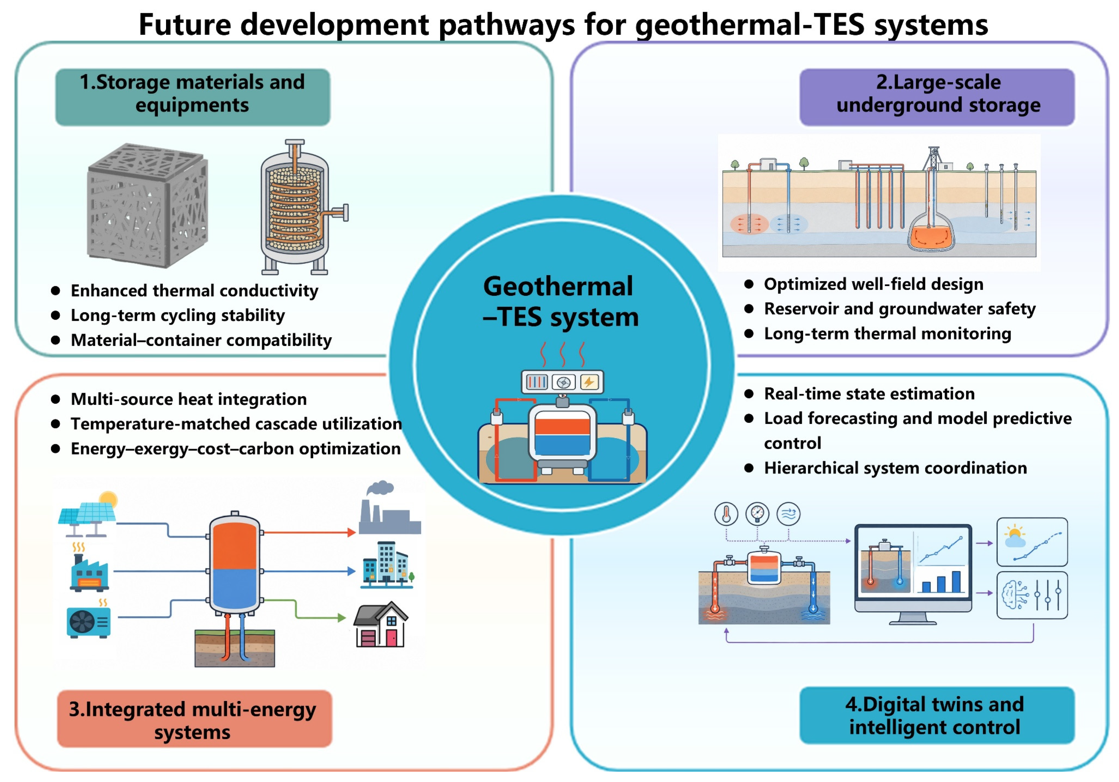
The immediate emphasis should be on making mature water-based and underground TES predictable, comparable, and financeable; medium-term effort should scale high-temperature and cross-depth demonstrations; and long-term effort should integrate storage across temperature grades and markets. This prioritization converts broad research themes into measurable gates for materials, field performance, economics, and control.
7. Conclusions
This review integrates a TES mechanism, geothermal-resource depth, timescale, technology readiness, and economics. The four questions posed in the introduction are answered as follows:
(1) Compatibility is conditional rather than universal. Shallow heat-pump systems are best matched with water tanks, low-temperature PCM, BTES, or ATES; medium-deep heating uses short-term water or PCM storage and, where geology permits, seasonal BTES or HT-ATES; deep power and cascade systems require higher-temperature sensible or thermochemical options. Temperature grade, geology, duration, and end use must be matched together.
(2) The timescale determines function. Short-term TES reduces cycling, shifts electricity demand, and supplies rapid peaks, whereas seasonal TES manages annual subsurface heat balance and raises geothermal-well utilization. Deliberately controlled short-cycle BTES lies between these categories and should be distinguished from ordinary transient ground exchange.
(3) Technology selection requires a multi-criteria assessment. Useful discharge temperature, recovery, auxiliary electricity, land and drilling, TRL, capital cost, operation and maintenance, and value under local tariffs are all material. Indicative ATES, BTES, and PTES capacity costs are low relative to many compact stores, but site conditions and utilization can reverse simple cost rankings.
(4) Coupling creates system-level constraints. Groundwater advection, thermal breakthrough, corrosion, scaling, reinjection, stable well flow, heat-pump temperature lift, and multi-temperature allocation must be managed jointly. The strongest evidence comes from monitored multi-year systems, including Nordic district-energy practice, rather than isolated numerical performance gains.
Near-term deployment should prioritize standardized reporting, monitored field validation, and integrated sizing of wells and storage. Medium-term work should demonstrate high-temperature and cross-depth underground storage with transparent economics. Long-term development should establish interoperable digital twins and multi-temperature geothermal hubs. These priorities provide a practical pathway from mature peak-shaving and seasonal-storage technologies toward flexible, large-scale geothermal energy systems.
Author Contributions
Conceptualization, Z.L., S.L., X.H. and X.Y.; investigation, Z.L., S.L., X.H. and X.Y.; writing—original draft preparation, Z.L., S.L., X.H. and X.Y.; writing—review and editing, Z.L., S.L., X.H. and X.Y. All authors have read and agreed to the published version of the manuscript.
Funding
This research was supported by the 2026 Annual Major Policy Consultation Project of Shanxi Provincial Government (Project No. ZB0601) and Horizontal Research Project of Taiyuan University (Project No. H2025054).
Data Availability Statement
No new data were created or analyzed in this study. Data sharing is not applicable to this article.
Conflicts of Interest
The authors declare no conflicts of interest.
References
- Billerbeck, A.; Kiefer, C.P.; Winkler, J.; Bernath, C.; Sensfuß, F.; Kranzl, L.; Müller, A.; Ragwitz, M. The race between hydrogen and heat pumps for space and water heating: A model-based scenario analysis. Energy Convers. Manag. 2024, 299, 117850. [Google Scholar] [CrossRef] [Scilit]
- Dang, L.M.; Shin, J.; Li, Y.; Tightiz, L.; Nguyen, T.N.; Song, H.-K.; Moon, H. Toward explainable heat load patterns prediction for district heating. Sci. Rep. 2023, 13, 7434. [Google Scholar] [CrossRef] [Scilit] [PubMed]
- Lee, J.Y.; Yim, T. Energy and flow demand analysis of domestic hot water in an apartment complex using a smart meter. Energy 2021, 229, 120678. [Google Scholar] [CrossRef] [Scilit]
- Ehsan, A.; Preece, R. Quantifying the impacts of heat decarbonisation pathways on the future electricity and gas demand. Energy 2022, 254, 124229. [Google Scholar] [CrossRef] [Scilit]
- Schöniger, F.; Mascherbauer, P.; Resch, G.; Kranzl, L.; Haas, R. The potential of decentral heat pumps as flexibility option for decarbonised energy systems. Energy Effic. 2024, 17, 26. [Google Scholar] [CrossRef] [Scilit]
- Vatanpour, A.; Nikooee, E.; Hataf, N. Geothermal energy as a sustainable energy resource: A review of mechanisms and systems of its extraction and storage. Geoenergy Sci. Eng. 2026, 265, 214563. [Google Scholar] [CrossRef] [Scilit]
- Kassem, M.A.; Moscariello, A. Geothermal energy: A sustainable and cost-effective alternative for clean energy production and climate change mitigation. Sustain. Futur. 2025, 10, 101247. [Google Scholar] [CrossRef] [Scilit]
- Yan, Y.; Shi, C.; Huang, G.; Wang, Y. Dynamically coupled modelling of ground source heat pump systems considering groundwater flow and unbalanced seasonal building thermal loads. Appl. Therm. Eng. 2025, 258, 124713. [Google Scholar] [CrossRef] [Scilit]
- Zhao, Y.; Gao, J.; Wu, F.; Sun, Y.; Liu, A.; Yu, Z.; Zhang, X. Study on the thermal imbalance characteristics and optimal operation strategy of ground source heat pump system in hot summer and cold winter areas. Energy Convers. Manag. 2025, 343, 120184. [Google Scholar] [CrossRef] [Scilit]
- Wang, Z.; Lu, M.; Wang, F.; Li, Y.; Bai, M.; Qin, H.; Ma, Z. Integrating seasonal borehole thermal energy storage into deep borehole ground source heat pump systems: Dynamic performance analysis under uncertainties. Energy Convers. Manag. 2025, 341, 120030. [Google Scholar] [CrossRef] [Scilit]
- Meng, B.; Zhou, Y.; Chen, W.; Luo, W.; Ding, R.; Cai, W.; Chen, C. Investigating the Impact of Seasonal Heat Storage on the Thermal and Economic Performance of a Deep Borehole Heat Exchanger: A Numerical Simulation Study. Buildings 2025, 15, 1575. [Google Scholar] [CrossRef] [Scilit]
- Zhang, J.; Chen, L.; Sun, Y.; Xu, L.; Zhao, X.; Li, Q.; Zhang, D. Geothermal resource distribution and prospects for development and utilization in China. Nat. Gas Ind. B 2024, 11, 6–18. [Google Scholar] [CrossRef] [Scilit]
- Xu, Y.-S.; Wang, X.-W.; Shen, S.-L.; Zhou, A. Distribution characteristics and utilization of shallow geothermal energy in China. Energy Build. 2020, 229, 110479. [Google Scholar] [CrossRef] [Scilit]
- Wang, S.; Zhou, Y.; Zhang, X.; Wang, Y.; Yang, Y.; Shang, Y.; Chen, Y.; Shi, X. Mapping and resource evaluation of deep high-temperature geothermal resources in the Jiyang Depression, China. Energy Geosci. 2024, 5, 100320. [Google Scholar] [CrossRef] [Scilit]
- He, Y.; Jia, M.; Li, X.; Yang, Z.; Song, R. Performance analysis of coaxial heat exchanger and heat-carrier fluid in medium-deep geothermal energy development. Renew. Energy 2021, 168, 938–959. [Google Scholar] [CrossRef] [Scilit]
- Breede, K.; Dzebisashvili, K.; Falcone, G. Overcoming challenges in the classification of deep geothermal potential. Geotherm. Energy Sci. 2015, 3, 19–39. [Google Scholar] [CrossRef] [Scilit]
- Brown, C.S.; Kolo, I.; Banks, D.; Falcone, G. Comparison of the thermal and hydraulic performance of single U-tube, double U-tube and coaxial medium-to-deep borehole heat exchangers. Geothermics 2024, 117, 102888. [Google Scholar] [CrossRef] [Scilit]
- Wang, S.; Hoes, P.-J.; Hensen, J.L.M.; Adan, O.C.G.; Donkers, P.A.J. A design optimization method for solar-driven thermochemical storage systems based on building performance simulation. J. Energy Storage 2023, 72, 108354. [Google Scholar] [CrossRef] [Scilit]
- Vilén, K.; Ahlgren, E.O. Seasonal large-scale thermal energy storage in an evolving district heating system—Long-term modeling of interconnected supply and demand. Smart Energy 2024, 15, 100156. [Google Scholar] [CrossRef] [Scilit]
- Nguyen, A.; Jacques, L.; Pasquier, P. Revisiting the potential of geothermal heat pump systems in cold climates with thermal energy storage. Energy Build. 2026, 363, 117545. [Google Scholar] [CrossRef] [Scilit]
- Vallese, L.; Javadi, H.; Badenes, B.; Urchueguia, J.F.; Lombardo, G.; Menegazzo, D.; Ure, Z.; Cesari, S.; Bottarelli, M.; Baccega, E.; et al. A comprehensive review of thermal energy storage technologies and their applications: Creation of a database. Renew. Sustain. Energy Rev. 2026, 225, 116133. [Google Scholar] [CrossRef] [Scilit]
- Zhang, Y.; Gao, X.; Sun, C.; Ye, C.; Gong, Y.; Kong, Y.; Pang, Z.; Li, H.; Lu, X.; Yao, Y. Thermal performance and analysis of high-temperature aquifer thermal energy storage based on a practical project. J. Energy Storage 2024, 82, 110399. [Google Scholar] [CrossRef] [Scilit]
- Saleem, A.; Ambreen, T.; Ugalde-Loo, C.E. Energy storage-integrated ground-source heat pumps for heating and cooling applications: A systematic review. J. Energy Storage 2024, 102, 114097. [Google Scholar] [CrossRef] [Scilit]
- Figueira, J.S.; García Gil, A.; Vieira, A.; Michopoulos, A.K.; Boon, D.P.; Loveridge, F.; Cecinato, F.; Götzl, G.; Epting, J.; Zosseder, K.; et al. Shallow geothermal energy systems for district heating and cooling networks: Review and technological progression through case studies. Renew. Energy 2024, 236, 121436. [Google Scholar] [CrossRef] [Scilit]
- Deng, J.; Peng, C.; Su, Y.; Qiang, W.; Cai, W.; Wei, Q. Research on the heat storage characteristic of deep borehole heat exchangers under intermittent operation mode: Simulation analysis and comparative study. Energy 2023, 282, 128938. [Google Scholar] [CrossRef] [Scilit]
- Huang, S.; Li, J.; Bai, Z.; Dong, J. Assessment of the effect of heat storage on the production of clean geothermal energy using the medium and deep U-type borehole heat exchanger system. J. Clean. Prod. 2024, 447, 141471. [Google Scholar] [CrossRef] [Scilit]
- Ma, J.; Wang, H.; Li, Y.; Ren, J.; Sun, H.; Du, S.; Wen, H. Heating and storage of medium-deep borehole heat exchangers: Analysis of operational characteristics via an optimized analytical solution model. J. Energy Storage 2024, 90, 111760. [Google Scholar] [CrossRef] [Scilit]
- Kökyay, Ş.; Aktaş, M.; Ünal, K.; Güven, Y.; Çakıroğlu, R.; Aktekeli, B. Development of hot and cold thermal energy storage system integrated with fuzzy logic control. Appl. Therm. Eng. 2025, 281, 128507. [Google Scholar] [CrossRef] [Scilit]
- Kumar, R.; Lee, D.; Ağbulut, Ü.; Kumar, S.; Thapa, S.; Thakur, A.; Jilte, R.D.; Saleel, C.A.; Shaik, S. Different energy storage techniques: Recent advancements, applications, limitations, and efficient utilization of sustainable energy. J. Therm. Anal. Calorim. 2024, 149, 1895–1933. [Google Scholar] [CrossRef] [Scilit]
- Zhao, C.; Yan, J.; Tian, X.; Xue, X.; Zhao, Y. Progress in thermal energy storage technologies for achieving carbon neutrality. Carbon Neutrality 2023, 2, 10. [Google Scholar] [CrossRef] [Scilit]
- Gaitero, J.J.; Prabhu, A.; Hochstein, D.; Mohammadi-Firouz, R.; Ouellet-Plamondon, C.; Bendouma, M.; Snoeck, D.; Ramón-Álvarez, I.; Sánchez-Delgado, S.; Torres-Carrasco, M.; et al. Reviewing experimental studies on sensible thermal energy storage in cementitious composites: Report of the RILEM TC 299-TES. Mater. Struct. 2024, 57, 100. [Google Scholar] [CrossRef] [Scilit]
- Xie, Y.; Liu, J.; Ma, W.; Sheng, J.; Zhang, P. Review of the heat transfer enhancement for phase change heat storage devices. J. Energy Storage 2024, 86, 111336. [Google Scholar] [CrossRef] [Scilit]
- Yan, T.; Xu, X.K.; Wang, Z.; Zhang, H.; Pan, W.G.; Wang, L.W. Review on solid-gas sorption heat storage: Materials, processes and system optimization. J. Energy Storage 2024, 100, 113589. [Google Scholar] [CrossRef] [Scilit]
- Liu, X.; Yang, F.; Liu, X.; Wu, Y. A systematic evaluation of sorption-based thermochemical energy storage for building applications: Material development, reactor design, and system integration. Renew. Energy 2025, 245, 122831. [Google Scholar] [CrossRef] [Scilit]
- Wang, X.; Zhang, H.; Cui, L.; Wang, J.; Lee, C.; Zhu, X.; Dong, Y. Borehole thermal energy storage for building heating application: A review. Renew. Sustain. Energy Rev. 2024, 203, 114772. [Google Scholar] [CrossRef] [Scilit]
- Kwasi-Effaha, C.C.; Okpako, O. Comprehensive review of emerging trends in thermal energy storage mechanisms, materials and applications. Front. Energy Res. 2025, 13, 1651471. [Google Scholar] [CrossRef] [Scilit]
- Mishra, L.; Sinha, A.; Majumder, P.; Gupta, R. Energy Storage Using Sensible Heat Storage Media: Thermal and Economic Considerations. In Recent Advances in Mechanical Engineering; Pandey, K.M., Misra, R.D., Patowari, P.K., Dixit, U.S., Eds.; Springer: Singapore, 2021; pp. 41–50. [Google Scholar]
- Wang, H.; Liu, J.; Wang, Y.; Zhao, Y.; Zhang, G. A review of the performance and application of molten salt-based phase change materials in sustainable thermal energy storage at medium and high temperatures. Appl. Energy 2025, 389, 125766. [Google Scholar] [CrossRef] [Scilit]
- Zemanek, J.; Vaclavik, A.; Hercik, R.; Byrtus, R.; Machacek, Z.; Schwär, F.; Walter, M.; Martinek, R.; Hameed, I.A.; Koziorek, J. Experimental evaluation of a modular phase-change material-based thermal energy storage system. Appl. Therm. Eng. 2026, 302, 131927. [Google Scholar] [CrossRef] [Scilit]
- Kumar, A.; Chopra, K.; Tyagi, V.V.; Popli, S.; Rajamony, R.K.; Islam, A.; Pandey, A.K. Shape stabilized phase change materials: Preparation techniques, emerging support matrices, artificial intelligence assisted optimization, and energy storage applications. J. Energy Storage 2026, 176, 123281. [Google Scholar] [CrossRef] [Scilit]
- Spietz, T.; Fryza, R.; Lasek, J.; Zuwała, J. Thermochemical Energy Storage Based on Salt Hydrates: A Comprehensive Review. Energies 2025, 18, 2643. [Google Scholar] [CrossRef] [Scilit]
- Arab, A.; Oppelt, L.; Chen, C.; Wiedener, R.; Späker, C.; Schenker, F.; Lotter, T.; Schneider, T.; Wunderlich, T.; Grab, T.; et al. Underground thermal energy storage in mines: Field scale heating-cooling cycles and performance at the Reiche Zeche underground mine. J. Energy Storage 2026, 163, 122087. [Google Scholar] [CrossRef] [Scilit]
- Shah, M.; Prajapati, M.; Yadav, K.; Sircar, A. A comprehensive review of geothermal energy storage: Methods and applications. J. Energy Storage 2024, 98, 113019. [Google Scholar] [CrossRef] [Scilit]
- Nordbeck, J.; Hornbruch, G.; Lüders, K.; Nordheim, J.N.; Werban, U.; Vogt, C.; Richnow, H.; Bauer, S. Experimental results of a High-Temperature-ATES field test: Induced convection, heat conduction and groundwater flow as efficiency-reducing processes. Geothermics 2026, 140, 103734. [Google Scholar] [CrossRef] [Scilit]
- Sifnaios, I.; Jensen, A.R. Performance analysis of the Høje Taastrup water pit thermal energy storage. J. Energy Storage 2025, 131, 117504. [Google Scholar] [CrossRef] [Scilit]
- Karim, A.; Burnett, A.; Fawzia, S. Investigation of Stratified Thermal Storage Tank Performance for Heating and Cooling Applications. Energies 2018, 11, 1049. [Google Scholar] [CrossRef] [Scilit]
- Kumar, K.; Singh, S. Investigating thermal stratification in a vertical hot water storage tank under multiple transient operations. Energy Rep. 2021, 7, 7186–7199. [Google Scholar] [CrossRef] [Scilit]
- Krüger, B.; Dammel, F.; Stephan, P. Investigating the aspect ratio’s influence on the exergetic performance and thermocline dynamics of a large water-based thermal energy storage system. J. Energy Storage 2024, 91, 112058. [Google Scholar] [CrossRef] [Scilit]
- Jodeiri, A.M.; Soppelsa, A.; Turrin, F.; Pipiciello, M.; Cozzini, M.; Fedrizzi, R. Numerical and experimental investigation of stratified water storage tanks: An enhanced adaptive-grid model. Appl. Therm. Eng. 2024, 248, 123113. [Google Scholar] [CrossRef] [Scilit]
- Lai, Z.; Hou, C.; Chen, J.; Guo, X.; Han, G.; Zhang, K.; Ding, L.; Lv, H. Experimental study on energy storage characteristics of packed bed using different solid materials. J. Energy Storage 2024, 100, 113701. [Google Scholar] [CrossRef] [Scilit]
- Kothari, R.; Hemmingsen, C.S.; Voigt, N.V.; La Seta, A.; Nielsen, K.K.; Desai, N.B.; Vijayan, A.; Haglind, F. Numerical and experimental analysis of instability in high temperature packed-bed rock thermal energy storage systems. Appl. Energy 2024, 358, 122535. [Google Scholar] [CrossRef] [Scilit]
- Wang, S.; Abdulridha, A.; Bravo, J.; Naito, C.; Quiel, S.; Suleiman, M.; Romero, C.; Neti, S. Thermal energy storage in concrete utilizing a thermosiphon heat exchanger. J. Energy Storage 2023, 64, 107201. [Google Scholar] [CrossRef] [Scilit]
- Shakeri, A.; Eshghi, H.; Salek, F.; Babaie, M. Energy assessment for integration of concrete thermal energy storage with low-grade solar power generation system. Renew. Energy 2023, 218, 119249. [Google Scholar] [CrossRef] [Scilit]
- Vera, J.; Odenthal, C.; Sanmartí, O.; Pérez-Segarra, C.D. Experimental characterisation and numerical modelling of a structured thermocline energy storage system under different operating conditions. J. Energy Storage 2026, 141, 119463. [Google Scholar] [CrossRef] [Scilit]
- Su, W.; Darkwa, J.; Kokogiannakis, G. Review of solid–liquid phase change materials and their encapsulation technologies. Renew. Sustain. Energy Rev. 2015, 48, 373–391. [Google Scholar] [CrossRef] [Scilit]
- Chalivendula, S.R.; Tarigonda, H. Recent Advances in Organic Phase Change Materials for Thermal Energy Storage: A Review on Sustainable Development Applications. Int. J. Thermophys. 2025, 46, 88. [Google Scholar] [CrossRef] [Scilit]
- Togun, H.; Basem, A.; Jweeg, M.J.; Biswas, N.; Abdulrazzaq, T.; Shelare, S.; Soudagar, M.E.M.; Chattopadhyay, A.; Paul, D.; Sadeq, A.M. Advances in inorganic and organic phase change materials for thermal energy storage: A comprehensive review of properties, challenges, and innovations. Appl. Therm. Eng. 2026, 302, 131668. [Google Scholar] [CrossRef] [Scilit]
- Fan, Y.; Wang, Z.; Guo, X.; Yang, S.; Jia, H.; Tao, Z.; Liu, J.; Yan, X.; Liu, Z.; Li, J. Expanded graphite/graphene composites for high through-plane thermal conductivity. Diam. Relat. Mater. 2024, 143, 110865. [Google Scholar] [CrossRef] [Scilit]
- Wang, S.-P.; Li, S.-Z.; Liu, W.-W.; Jiang, N.; Bai, L.; Bao, R.-Y.; Yang, J.; Yang, W. Enhanced leakage-proof performance of flexible phase change materials through the transformation of physicochemical crosslinked networks. Polymer 2025, 326, 128357. [Google Scholar] [CrossRef] [Scilit]
- Sun, J.; Qin, J.; Xu, L.; Song, Z.; Zhao, L. Improving Supercooling and Properties of Hydrated Salt Phase-Change Materials Using Binary Nucleating Agent. Energies 2026, 19, 2889. [Google Scholar] [CrossRef] [Scilit]
- Arslan, B.; Ilbas, M. Experimental and Numerical Investigation of Macroencapsulated Phase Change Materials for Thermal Energy Storage. Materials 2024, 17, 2804. [Google Scholar] [CrossRef] [Scilit] [PubMed]
- Li, Y.; Huang, X.; Li, Z.; Xie, Y.; Yang, X.; Li, M.-J. Structural optimization of latent heat storage tank filled with nickel foam. Appl. Therm. Eng. 2025, 267, 125780. [Google Scholar] [CrossRef] [Scilit]
- Tien Nguyen, G.; Tran Thi, N.; Thanh Nho, N.; Duy Hanh, L.T.; Anh Tuan, H.N. A novel stearic acid/expanded graphite/Fe3O4 composite phase change material with effective photo/electro/magneto-triggered thermal conversion and storage for thermotherapy applications. J. Sci. Adv. Mater. Dev. 2024, 9, 100792. [Google Scholar] [CrossRef] [Scilit]
- Hu, X.; Chen, P.; Guo, X.; Zhang, X. Numerical investigation on thermal behavior of PCM embedded in structured porous fins (SPFs) with various configurations and materials. Appl. Therm. Eng. 2025, 274, 126617. [Google Scholar] [CrossRef] [Scilit]
- Ye, R.; Wang, J.; Li, Y.; Sun, W.; Huang, Q.; Gong, S.; Shu, X. Preparation and Characteristics of Na2HPO4·12H2O-K2HPO4·3H2O/SiO2 Composite Phase Change Materials for Thermal Energy Storage. Materials 2022, 15, 7600. [Google Scholar] [CrossRef] [Scilit] [PubMed]
- Zhou, D.; Xiao, S.; Liu, Y. The Effect of Expanded Graphite Content on the Thermal Properties of Fatty Acid Composite Materials for Thermal Energy Storage. Molecules 2024, 29, 3146. [Google Scholar] [CrossRef] [Scilit] [PubMed]
- Hu, X.; Chen, P.; Zhang, X.; Gong, X.; Shuai, Y.; Wang, Y.; Xing, X.; Zheng, X.; Wang, G. Experimental and numerical study on thermal management performance of PCM-based heat sinks with various configurations fabricated by additive manufacturing. Renew. Energy 2024, 232, 121069. [Google Scholar] [CrossRef] [Scilit]
- Milone, C.; Kato, Y.; Mastronardo, E. Thermal Energy Storage with Chemical Reactions. In Recent Advancements in Materials and Systems for Thermal Energy Storage: An Introduction to Experimental Characterization Methods; Frazzica, A., Cabeza, L.F., Eds.; Springer International Publishing: Cham, Switzerland, 2019; pp. 15–32. [Google Scholar]
- Agalit, H.; Wang, Y.; Lu, T.; Qiao, G.; Chaomurilige; Ding, Y.; Li, Y. Towards an agglomeration free Ca(OH)2/CaO thermochemical energy storage loop via nanofabricated hollow CaO microspheres with highly porous shells. Chem. Eng. J. 2024, 493, 152632. [Google Scholar] [CrossRef] [Scilit]
- Shervani, S.; Strong, C.; Tezel, F.H. Simultaneous impregnation and microencapsulation of CaCl2 using silica gel and methyl cellulose for thermal energy storage applications. Sci. Rep. 2024, 14, 7183. [Google Scholar] [CrossRef] [Scilit] [PubMed]
- Schmit, H.; Pöllinger, S.; Schubert, T.; Lävemann, E.; Hiebler, S. Application oriented material characterisation and simulation for adsorption thermal energy storage. Front. Therm. Eng. 2025, 5, 1513507. [Google Scholar] [CrossRef] [Scilit]
- Abohamzeh, E.; Hosseinizadeh, S.E.; Frey, G. Numerical investigation and response surface optimization of a sorption heat storage systems performance using Y-shaped fins. J. Energy Storage 2024, 84, 110803. [Google Scholar] [CrossRef] [Scilit]
- Witter, E.; Dobson, P.; Akindipe, D.; McTigue, J.; Atkinson, T.; Kumar, R.; Sonnenthal, E.; Zhu, G. A review of Geological Thermal Energy Storage for seasonal, grid-scale dispatching. Renew. Sustain. Energy Rev. 2025, 218, 115761. [Google Scholar] [CrossRef] [Scilit]
- Brown, C.S.; Kolo, I.; Lyden, A.; Franken, L.; Kerr, N.; Marshall-Cross, D.; Watson, S.; Falcone, G.; Friedrich, D.; Diamond, J. Assessing the technical potential for underground thermal energy storage in the UK. Renew. Sustain. Energy Rev. 2024, 199, 114545. [Google Scholar] [CrossRef] [Scilit]
- Kvalsvik, K.H.; Ramstad, R.K.; Holmberg, H.; Kocbach, J. Measurements and simulations of high temperature borehole thermal energy storage in Drammen, Norway—Evaluation of thermal losses and thermal barrier. Geothermics 2025, 125, 103192. [Google Scholar] [CrossRef] [Scilit]
- Xiang, Y.; Xie, Z.; Furbo, S.; Wang, D.; Gao, M.; Fan, J. A comprehensive review on pit thermal energy storage: Technical elements, numerical approaches and recent applications. J. Energy Storage 2022, 55, 105716. [Google Scholar] [CrossRef] [Scilit]
- Villeneuve, M.; Loucky, G.; Galler, R.; Hörtler, M.; Dahash, A.; Neumayr, T.; Strubreiter, B.; Messerklinger, S.; Moser, S. HEATROCK—Cavern Thermal Energy Storage in Crystalline Rocks. BHM Berg-Hüttenmänn. Mon. 2025, 170, 759–765. [Google Scholar] [CrossRef] [Scilit]
- Wang, J.; Ding, Y.; Liang, G.; Li, X.; Luo, Y.; Hou, P.; Li, Y.; Zhao, J. A review on direct expansion ground heat exchanger: Experimental advancement, system instability, and heat transfer model. Renew. Sustain. Energy Rev. 2026, 226, 116227. [Google Scholar] [CrossRef] [Scilit]
- Cui, P.; Yang, W.; Zhang, W.; Zhu, K.; Spitler, J.D.; Yu, M. Advances in ground heat exchangers for space heating and cooling: Review and perspectives. Energy Built Environ. 2024, 5, 255–269. [Google Scholar] [CrossRef] [Scilit]
- Wang, X.; Zhou, Y.; Yao, W.; Xia, Y.; Xu, T.; Yang, H.; Xie, H.; Gao, W. The challenge of the ground heat Exchangers: A review of heat transfer efficiency. Energy Convers. Manag. 2024, 302, 118115. [Google Scholar] [CrossRef] [Scilit]
- Soltan Mohammadi, H.; Ringel, L.M.; Bott, C.; Bayer, P. Adaptive management of borehole heat exchanger fields under transient groundwater flow conditions. Renew. Energy 2024, 234, 121060. [Google Scholar] [CrossRef] [Scilit]
- Piipponen, K.; Soesoo, A.; Arola, T.; Bauert, H.; Tarros, S. Impacts of groundwater flow on borehole heat exchangers: Lessons learned from Estonia. Renew. Energy 2024, 237, 121448. [Google Scholar] [CrossRef] [Scilit]
- Heim, E.; Stoffel, P.; Müller, D.; Klitzsch, N. Six years of high-resolution monitoring data of 40 borehole heat exchangers. Sci. Data 2024, 11, 1334. [Google Scholar] [CrossRef] [Scilit] [PubMed]
- Stemmle, R.; Lee, H.; Blum, P.; Menberg, K. City-scale heating and cooling with aquifer thermal energy storage (ATES). Geotherm. Energy 2024, 12, 2. [Google Scholar] [CrossRef] [Scilit]
- Sezer, T.; Sani, A.K.; Singh, R.M.; Cui, L.; Boon, D.P.; Woods, M. Numerical investigation of a district scale groundwater heat pump system: A case study from Colchester, UK. Appl. Therm. Eng. 2024, 236, 121915. [Google Scholar] [CrossRef] [Scilit]
- Mohamad, Z.; Fardoun, F.; Meftah, F. A review on energy piles design, evaluation, and optimization. J. Clean. Prod. 2021, 292, 125802. [Google Scholar] [CrossRef] [Scilit]
- Liu, R.Y.W.; Taborda, D.M.G. The effects of thermal interference on the thermal performance of thermo-active pile groups. Renew. Energy 2024, 225, 120357. [Google Scholar] [CrossRef] [Scilit]
- Liu, X.; Tian, Y.; Liu, Y.; Liu, W.; Zheng, L.; Li, X. Efficient Development and Utilization of Geothermal Energy: An Analysis of the Operational Strategy for Deep-Buried Pipe-Type Energy Piles Considering Seepage Effects. Sustainability 2025, 17, 1634. [Google Scholar] [CrossRef] [Scilit]
- Ma, Q.; Lu, J.; Jia, J.; Fan, J. Model predictive control of energy pile-based space heating and cooling systems under future weather conditions. Renew. Energy 2026, 256, 123937. [Google Scholar] [CrossRef] [Scilit]
- Stegemerten, F.; Hestert, R.; Römer, F.; Rätz, M.; Müller, D. The impact of buffer tank size on explicit flexibility in residential buildings: A model predictive control analysis. J. Energy Storage 2026, 165, 122239. [Google Scholar] [CrossRef] [Scilit]
- Tonellato, G.; Kummert, M.; Candanedo, J.; Beaudry, G.; Pasquier, P. A model-based continuous commissioning method for an efficient integration of ground source heat pumps in the building ecosystem. Energy Build. 2025, 333, 115492. [Google Scholar] [CrossRef] [Scilit]
- Xue, T.; Jokisalo, J.; Kosonen, R. Demand Response Potential of an Educational Building Heated by a Hybrid Ground Source Heat Pump System. Energies 2024, 17, 5428. [Google Scholar] [CrossRef] [Scilit]
- Kallioharju, K.; Ylipaino, J.; Kortetmäki, A.; Virta, A.; Järventausta, P.; Sormunen, P. Design and sizing practices of ground source heat pump systems in Finnish multi-apartment building retrofits. Build. Serv. Eng. Res. Technol. 2026, 47, 447–468. [Google Scholar] [CrossRef] [Scilit]
- Liu, J.; Yu, H.; Ji, H.; Zhao, K.; Lv, C.; Li, P. Optimal Operation Strategy of a Community Integrated Energy System Constrained by the Seasonal Balance of Ground Source Heat Pumps. Sustainability 2020, 12, 4627. [Google Scholar] [CrossRef] [Scilit]
- Xue, T.; Jokisalo, J.; Kosonen, R.; Ju, Y. Design of High-Performing Hybrid Ground Source Heat Pump (GSHP) System in an Educational Building. Buildings 2023, 13, 1825. [Google Scholar] [CrossRef] [Scilit]
- Kim, D.; Kim, H.J.; Tak, H.; Lee, J.Y. Field evaluation of a soft actor–critic-based control strategy for a centralized geothermal heat pump system. Energy Convers. Manag. 2026, 354, 121248. [Google Scholar] [CrossRef] [Scilit]
- Ryu, S.-B.; Heo, S.; Yook, S.-J. Performance evaluation of a hybrid ground source heat pump system with thermal recovery and intermittent operation strategies. Case Stud. Therm. Eng. 2025, 75, 107102. [Google Scholar] [CrossRef] [Scilit]
- Mancin, S.; Noro, M. Reversible Heat Pump Coupled with Ground Ice Storage for Annual Air Conditioning: An Energy Analysis. Energies 2020, 13, 6182. [Google Scholar] [CrossRef] [Scilit]
- Rae, C.; Bhagavathy, S.; Thorpe, B. Assessing the demand flexibility of storage-integrated heat pumps: A heating Hardware-In-the-Loop approach. In Proceedings of the 2025 IEEE PES Innovative Smart Grid Technologies Conference Europe (ISGT Europe); IEEE: Piscataway, NJ, USA, 2025; pp. 1–5. [Google Scholar]
- Zhu, C.; Xin, Y.; Dong, L.; Zhao, J.; Chen, Z.; Zhang, T.; Qu, Y.; Wang, F. Research on the Short-Term Borehole Thermal Energy Storage Characteristics of Ground Heat Exchangers. In Proceedings of the 2025 4th International Conference on Renewable Energy and Electrical Technology (ICREET), Kunming, China, 26–28 September 2025; pp. 33–37. [Google Scholar]
- Desguers, T.; Brown, C.S.; Kolo, I.; Banks, D.; Falcone, G.; Friedrich, D. Short-cycle borehole thermal energy storage: Impact of thermal cycle duration on overall performance. Appl. Therm. Eng. 2025, 258, 124610. [Google Scholar] [CrossRef] [Scilit]
- Sadeghi, H.; Jalali, R.; Singh, R.M. A review of borehole thermal energy storage and its integration into district heating systems. Renew. Sustain. Energy Rev. 2024, 192, 114236. [Google Scholar] [CrossRef] [Scilit]
- Ahmadfard, M.; Baniasadi, E. Borehole thermal energy storage systems: A comprehensive review using bibliometric and qualitative tools. Appl. Energy 2025, 387, 125638. [Google Scholar] [CrossRef] [Scilit]
- Lepinay, E.; Woods, A.W. Controls on the temperature of the produced fluid in a double well ATES system. Renew. Energy 2025, 244, 122508. [Google Scholar] [CrossRef] [Scilit]
- Tas, L.; Hartog, N.; Bloemendal, M.; Simpson, D.; Robert, T.; Thibaut, R.; Zhang, L.; Hermans, T. Efficiency and heat transport processes of low-temperature aquifer thermal energy storage systems: New insights from global sensitivity analyses. Geotherm. Energy 2025, 13, 2. [Google Scholar] [CrossRef] [Scilit]
- Todorov, O.; Alanne, K.; Virtanen, M.; Kosonen, R. Aquifer Thermal Energy Storage (ATES) for District Heating and Cooling: A Novel Modeling Approach Applied in a Case Study of a Finnish Urban District. Energies 2020, 13, 2478. [Google Scholar] [CrossRef] [Scilit]
- Kolo, I.; Brown, C.S.; Nibbs, W.; Cai, W.; Falcone, G.; Nagel, T.; Chen, C. A comprehensive review of deep borehole heat exchangers (DBHEs): Subsurface modelling studies and applications. Geotherm. Energy 2024, 12, 19. [Google Scholar] [CrossRef] [Scilit]
- Borko, K.; Brenčič, M.; Savšek, Z.; Knez, J.; Vozelj, A.; Kisel, G.; Rman, N. Insights into Aquifer and Borehole Thermal Energy Storage Systems for Slovenia’s Energy Transition. Energies 2025, 18, 1019. [Google Scholar] [CrossRef] [Scilit]
- Asan, E.; Ozturk, Z.F.; Abali, B.E.; Sisman, A. Groundwater flow impacts on very high temperature borehole thermal energy storage performance. Energy Build. 2025, 349, 116568. [Google Scholar] [CrossRef] [Scilit]
- Miceli, A.V.; Buscemi, A.; Guarino, S.; Beccali, M.; Lo Brano, V. Modelling of borehole thermal energy storages: A g-function approach with a novel load aggregation scheme. Energy Convers. Manag. 2026, 348, 120666. [Google Scholar] [CrossRef] [Scilit]
- Zhao, D.; Cui, M.; Yang, S.; Li, X.; Huo, J.; Yin, Y. Rapid Temperature Prediction Model for Large-Scale Seasonal Borehole Thermal Energy Storage Unit. Energies 2025, 18, 5326. [Google Scholar] [CrossRef] [Scilit]
- Carlsson, A.E. Coarse-Grained Model of Underground Thermal Energy Storage Applied to Efficiency Optimization. Energies 2020, 13, 1918. [Google Scholar] [CrossRef] [Scilit]
- Chicco, J.M.; Mandrone, G. Modelling the Energy Production of a Borehole Thermal Energy Storage (BTES) System. Energies 2022, 15, 9587. [Google Scholar] [CrossRef] [Scilit]
- Gholizadeh Doonechaly, N.; Halter, T.; Shakas, A.; Hefny, M.; Brehme, M.; Hertrich, M.; Giardini, D. Thermal Energy Storage and Recovery in Fractured Granite Reservoirs: Numerical Modeling and Efficiency Analysis. Geosciences 2024, 14, 357. [Google Scholar] [CrossRef] [Scilit]
- Petrova, E.; Cacace, M.; Kranz, S.; Zang, A.; Blöcher, G. Thermal interference in aquifer thermal energy storage: Insights from stochastic surrogate modelling of well placement. Appl. Therm. Eng. 2025, 278, 127012. [Google Scholar] [CrossRef] [Scilit]
- Nordheim, J.N.; Beyer, C.; Bauer, S. Integrating hydraulic and thermal constraints for ATES well placements: An analytical approach. Hydrogeol. J. 2026, 34, 1475–1497. [Google Scholar] [CrossRef] [Scilit]
- Chen, Z.; Zhang, J.; Zhan, H. Analysis of the impact of ambient groundwater flow on the aquifer thermal energy storage systems. J. Hydrol. 2025, 658, 133140. [Google Scholar] [CrossRef] [Scilit]
- Tang, D.W.S.; Rijnaarts, H.H.M. Dimensionless Thermal Efficiency Analysis for Aquifer Thermal Energy Storage. Water Resour. Res. 2023, 59, e2023WR035797. [Google Scholar] [CrossRef] [Scilit]
- Chen, K.; Sun, X.; Soga, K.; Nico, P.S.; Dobson, P.F. Machine-learning-assisted long-term G functions for bidirectional aquifer thermal energy storage system operation. Energy 2024, 301, 131638. [Google Scholar] [CrossRef] [Scilit]
- Skarphagen, H.; Banks, D.; Frengstad, B.S.; Gether, H. Design Considerations for Borehole Thermal Energy Storage (BTES): A Review with Emphasis on Convective Heat Transfer. Geofluids 2019, 2019, 4961781. [Google Scholar] [CrossRef] [Scilit]
- Lundh, M.; Dalenbäck, J.O. Swedish solar heated residential area with seasonal storage in rock: Initial evaluation. Renew. Energy 2008, 33, 703–711. [Google Scholar] [CrossRef] [Scilit]
- Fleuchaus, P.; Godschalk, B.; Stober, I.; Blum, P. Worldwide application of aquifer thermal energy storage—A review. Renew. Sustain. Energy Rev. 2018, 94, 861–876. [Google Scholar] [CrossRef] [Scilit]
- Chen, H.; Li, X.; Gao, J.; Cao, J.; Dong, H.; Wang, W.; Chen, Y. Comparative study on a solar-assisted ground source heat pump with CPC solar collector and phase change heat storage. Renew. Energy 2025, 239, 122065. [Google Scholar] [CrossRef] [Scilit]
- Alhassan, S.; Haruna, B.; Garba, D.; Abdullahi Muhammad, A.; Muhammad, S.; Muhammad, J.Y. Hybrid solar–ground source heat pump systems for net-zero energy buildings: A review of thermal management, energy storage, and optimization approaches. Int. J. Energy Stud. 2026, 11, 1585–1611. [Google Scholar] [CrossRef] [Scilit]
- Huang, X.; Li, M.; Li, Y.; Yang, X.; He, Y.-L. Current progress in energy utilization of building systems combining solar thermal and heat storage technologies. Renew. Sustain. Energy Rev. 2026, 226, 116330. [Google Scholar] [CrossRef] [Scilit]
- Yu, M.G.; Nam, Y.; Yu, Y.; Seo, J. Study on the System Design of a Solar Assisted Ground Heat Pump System Using Dynamic Simulation. Energies 2016, 9, 291. [Google Scholar] [CrossRef] [Scilit]
- Sazon, T.A.; Zhang, Q.; Nikpey, H. Comparison of different configurations of a solar-assisted ground-source CO2 heat pump system for space and water heating using Taguchi-Grey Relational analysis. Energy Convers. Manag. 2024, 300, 117881. [Google Scholar] [CrossRef] [Scilit]
- Cao, Y.; Zhang, Z.; Jia, G.; Zhai, J.; Hao, J.; Zhang, M.; Jin, L. Performance Prediction and Analysis of Solar-Assisted Ground-Source Heat Pump Systems in Typical Rural Areas, China. Energies 2025, 18, 2208. [Google Scholar] [CrossRef] [Scilit]
- Li, Y.; Zhang, L.; Zhang, W.; Luo, H.; Yang, X.; Sundén, B. Multi-strategy collaborative optimization of a rotational thermal storage system with radial gradient metal foams. Appl. Therm. Eng. 2026, 303, 132310. [Google Scholar] [CrossRef] [Scilit]
- Liravi, M.; Karkon, E.; Jamot, J.; Wemhoener, C.; Dai, Y.; Georges, L. Energy efficiency and borehole sizing for photovoltaic-thermal collectors integrated to ground source heat pump system: A Nordic case study. Energy Convers. Manag. 2024, 313, 118590. [Google Scholar] [CrossRef] [Scilit]
- Pourier, C.; Beltrán, F.; Sommerfeldt, N. Solar photovoltaic/thermal (PVT) technology collectors and free cooling in ground source heat pump systems. Sol. Energy Adv. 2024, 4, 100050. [Google Scholar] [CrossRef] [Scilit]
- Ocłoń, P.; Ławryńczuk, M.; Czamara, M. A New Solar Assisted Heat Pump System with Underground Energy Storage: Modelling and Optimisation. Energies 2021, 14, 5137. [Google Scholar] [CrossRef] [Scilit]
- Tong, W.; Yu, Q.; Jia, C. Design and simulation of a ground-source heat pump system coupled with solar heating. Int. J. Low-Carbon Technol. 2025, 20, 1184–1193. [Google Scholar] [CrossRef] [Scilit]
- Drews, M.C.; Pfrang, D.; Schölderle, F.; Zosseder, K. Assessment criteria and risk mitigation of hydrogeothermal energy portfolios for district heating. Commun. Eng. 2025, 4, 138. [Google Scholar] [CrossRef] [Scilit] [PubMed]
- Gascuel, V.; Rivard, C.; Raymond, J. Deep geothermal doublets versus deep borehole heat exchangers: A comparative study for cold sedimentary basins. Appl. Energy 2024, 361, 122826. [Google Scholar] [CrossRef] [Scilit]
- White, M.; Vasyliv, Y.; Beckers, K.; Martinez, M.; Balestra, P.; Parisi, C.; Augustine, C.; Bran-Anleu, G.; Horne, R.; Pauley, L.; et al. Numerical investigation of closed-loop geothermal systems in deep geothermal reservoirs. Geothermics 2024, 116, 102852. [Google Scholar] [CrossRef] [Scilit]
- Lund, A.E.D. Effect of heat and mass transfer related parameters on the performance of deep borehole heat exchangers. Appl. Therm. Eng. 2024, 253, 123764. [Google Scholar] [CrossRef] [Scilit]
- Aljubran, M.J.; Horne, R.N. Power supply characterization of baseload and flexible enhanced geothermal systems. Sci. Rep. 2024, 14, 17619. [Google Scholar] [CrossRef] [Scilit] [PubMed]
- Bu, X.; Chen, W.; Du, J.; Wang, L. Performance analysis of high temperature thermal energy storage in shallow depth enhanced geothermal system. Front. Built Environ. 2024, 10, 1486884. [Google Scholar] [CrossRef] [Scilit]
- Ayadi, B.; Jasim, D.J.; Anqi, A.E.; Aich, W.; Rajhi, W.; Marefati, M. Multi-criteria/comparative analysis and multi-objective optimization of a hybrid solar/geothermal source system integrated with a carnot battery. Case Stud. Therm. Eng. 2024, 54, 104031. [Google Scholar] [CrossRef] [Scilit]
- Agson-Gani, P.H.; Regenauer-Lieb, K.; Taylor, R.A.; Roshan, H.; Rahman, S.S. An ultra-high-temperature geothermal battery for sustainable solar power. Energy Convers. Manag. 2025, 341, 119892. [Google Scholar] [CrossRef] [Scilit]
- Liu, D.; Gu, D.; Zhang, W.; Ren, Y.; Sun, T. Performance and economic analysis of a novel water storage tank coupled with geothermal heating System: A field test. Appl. Therm. Eng. 2024, 255, 124012. [Google Scholar] [CrossRef] [Scilit]
- Liu, D.; Zhang, W.; Gu, D.; Sun, T. Experimental study on a new type of water storage tank for geothermal heating. Geothermics 2024, 118, 102918. [Google Scholar] [CrossRef] [Scilit]
- Zhu, C.; Quan, C.; Shi, P.; Li, B.; Zhang, J.; Li, M. Analysis and optimization of a medium-depth ground source heat pump heating systems with heat storage and borehole heat exchangers. Energy Rep. 2024, 11, 1455–1471. [Google Scholar] [CrossRef] [Scilit]
- Zhang, L.; Chen, J.; Li, Y.; Yuan, T.; Li, K.; Li, M. Study on operational performance and multi-objective optimization of a solar-wind- heat storage coupled medium-depth ground source heat pump. Case Stud. Therm. Eng. 2026, 80, 107887. [Google Scholar] [CrossRef] [Scilit]
- Moustakidis, S.; Meintanis, I.; Halikias, G.; Karcanias, N. An Innovative Control Framework for District Heating Systems: Conceptualisation and Preliminary Results. Resources 2019, 8, 27. [Google Scholar] [CrossRef] [Scilit]
- Xing, Y.; Zhang, X.; Zhang, Z.; Liu, F. The Impact of Inlet Structure on Stratification Performance in Thermal Storage Tanks: A Study through Simulation and Experimental Analysis. Appl. Sci. 2024, 14, 5248. [Google Scholar] [CrossRef] [Scilit]
- Trojan, M.; Taler, D.; Dzierwa, P.; Taler, J.; Kaczmarski, K.; Wrona, J. The use of pressure hot water storage tanks to improve the energy flexibility of the steam power unit. Energy 2019, 173, 926–936. [Google Scholar] [CrossRef] [Scilit]
- Staub, S.; Bazan, P.; Braimakis, K.; Müller, D.; Regensburger, C.; Scharrer, D.; Schmitt, B.; Steger, D.; German, R.; Karellas, S.; et al. Reversible Heat Pump–Organic Rankine Cycle Systems for the Storage of Renewable Electricity. Energies 2018, 11, 1352. [Google Scholar] [CrossRef] [Scilit]
- Boysen, C.; Kaldemeyer, C.; Hilpert, S.; Tuschy, I. Integration of Flow Temperatures in Unit Commitment Models of Future District Heating Systems. Energies 2019, 12, 1061. [Google Scholar] [CrossRef] [Scilit]
- Scharrer, D.; Eppinger, B.; Schmitt, P.; Zenk, J.; Bazan, P.; Karl, J.; Will, S.; Pruckner, M.; German, R. Life Cycle Assessment of a Reversible Heat Pump–Organic Rankine Cycle–Heat Storage System with Geothermal Heat Supply. Energies 2020, 13, 3253. [Google Scholar] [CrossRef] [Scilit]
- Liu, H.; Guo, J.; Li, B.; Rodriguez-Dono, A.; Huang, P.; Li, X.; Topal, E.; Liu, S. Assessing the Performance of a Cascaded Composite Phase Change Material Roadway Cooling System Against Heat Hazard from Sustainable Mine Geothermal Energy. Appl. Sci. 2025, 15, 11850. [Google Scholar] [CrossRef] [Scilit]
- Coelho, L.; Koukou, M.K.; Dogkas, G.; Konstantaras, J.; Vrachopoulos, M.G.; Rebola, A.; Benou, A.; Choropanitis, J.; Karytsas, C.; Sourkounis, C.; et al. Latent Thermal Energy Storage Application in a Residential Building at a Mediterranean Climate. Energies 2022, 15, 1008. [Google Scholar] [CrossRef] [Scilit]
- Nair, A.M.; Wilson, C.; Kamkari, B.; Hodge, S.; Jun Huang, M.; Griffiths, P.; Hewitt, N.J. Energy and exergy analysis of a multipass macro-encapsulated phase change material/expanded graphite composite thermal energy storage for domestic hot water applications. Energy Convers. Manag. X 2024, 24, 100788. [Google Scholar] [CrossRef] [Scilit]
- Raheem, A.I.; Pesteei, S.M.; Yaqob, B.N. Experimental study on thermocline behavior and management in phase change material-enhanced thermal energy storage: Implications for charging and discharging cycles. Energy Convers. Manag. X 2024, 24, 100816. [Google Scholar] [CrossRef] [Scilit]
- Huang, X.; Li, Y.; Lu, L.; Gao, X.; Yang, X.; Li, M.-J. Numerical investigations on heat release performance of phase change mixture of paraffin and water. Sol. Energy Mater. Sol. Cells 2025, 280, 113266. [Google Scholar] [CrossRef] [Scilit]
- Iung, A.; Simo Tala, J.V.; Bahrani, S.A.; Lagardere Deleglise, M. Investigation of the melting and solidification processes of a phase change material in cylindrical annular enclosures: A parametric study for energy densification in hot water tanks. J. Energy Storage 2024, 103, 114375. [Google Scholar] [CrossRef] [Scilit]
- Hirvijoki, E.; Hirvonen, J. The potential of intermediate-to-deep geothermal boreholes for seasonal storage of district heat. Renew. Energy 2022, 198, 825–832. [Google Scholar] [CrossRef] [Scilit]
- Brown, C.S.; Kolo, I.; Falcone, G.; Banks, D. Repurposing a deep geothermal exploration well for borehole thermal energy storage: Implications from statistical modelling and sensitivity analysis. Appl. Therm. Eng. 2023, 220, 119701. [Google Scholar] [CrossRef] [Scilit]
- Krusemark, M.; Seib, L.; Pham, H.; Sass, I. Construction of a medium-deep geothermal storage system: Case study of the SKEWS MD-BTES demosite. Geothermics 2026, 136, 103579. [Google Scholar] [CrossRef] [Scilit]
- Oerlemans, P.; Drijver, B.; Koenen, M.; Koornneef, J.; Dinkelman, D.; Bos, W.; Godschalk, B. First field results on the technical risks and effectiveness of mitigation measures for the full scale HT-ATES demonstration project in Middenmeer. In Proceedings of the European Geothermal Congress 2022, Berlin, Germany, 17–21 October 2022. [Google Scholar]
- Szklarz, S.P.; Dinkelman, D.; Khoshnevis Gargar, N.; Boullenger, B.; Peters, E.; Barros, E.G.D.; Koenen, M. Ensemble-based assisted history matching of DTS monitoring data in HT-ATES systems: Application to a real-life case study. Geotherm. Energy 2024, 12, 46. [Google Scholar] [CrossRef] [Scilit]
- Geerts, D.; Liu, W.; Daniilidis, A.; Vardon, P.J.; Kramer, G.J. Techno-economic analysis of High-Temperature Aquifer Thermal Energy Storage in district heating systems. Energy Convers. Manag. X 2026, 30, 101667. [Google Scholar] [CrossRef] [Scilit]
- Major, M.; Poulsen, S.E.; Balling, N. A numerical investigation of combined heat storage and extraction in deep geothermal reservoirs. Geotherm. Energy 2018, 6, 1. [Google Scholar] [CrossRef] [Scilit]
- Scapino, L.; De Servi, C.; Zondag, H.A.; Diriken, J.; Rindt, C.C.M.; Sciacovelli, A. Techno-economic optimization of an energy system with sorption thermal energy storage in different energy markets. Appl. Energy 2020, 258, 114063. [Google Scholar] [CrossRef] [Scilit]
- Operacz, A.; Zachora-Buławska, A.; Strzelecka, I.; Buda, M.; Bielec, B.; Migdał, K.; Operacz, T. The Standard Geothermal Plant as an Innovative Combined Renewable Energy Resources System: The Case from South Poland. Energies 2022, 15, 6398. [Google Scholar] [CrossRef] [Scilit]
- Li, T.; Li, X.; Gao, H.; Gao, X.; Meng, N. Thermodynamic Performance of Geothermal Energy Cascade Utilization for Combined Heating and Power Based on Organic Rankine Cycle and Vapor Compression Cycle. Energies 2022, 15, 7294. [Google Scholar] [CrossRef] [Scilit]
- Stoikos, A.; Kyriakides, A.-S.; Carneiro, J.; Behnous, D.; Gravanis, G.; Tsimpanogiannis, I.N.; Seferlis, P.; Voutetakis, S. Analysis and Evaluation of a TCO2 Electrothermal Energy Storage System with Integration of CO2 Geological Storage. Energies 2025, 18, 601. [Google Scholar] [CrossRef] [Scilit]
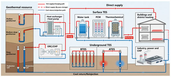
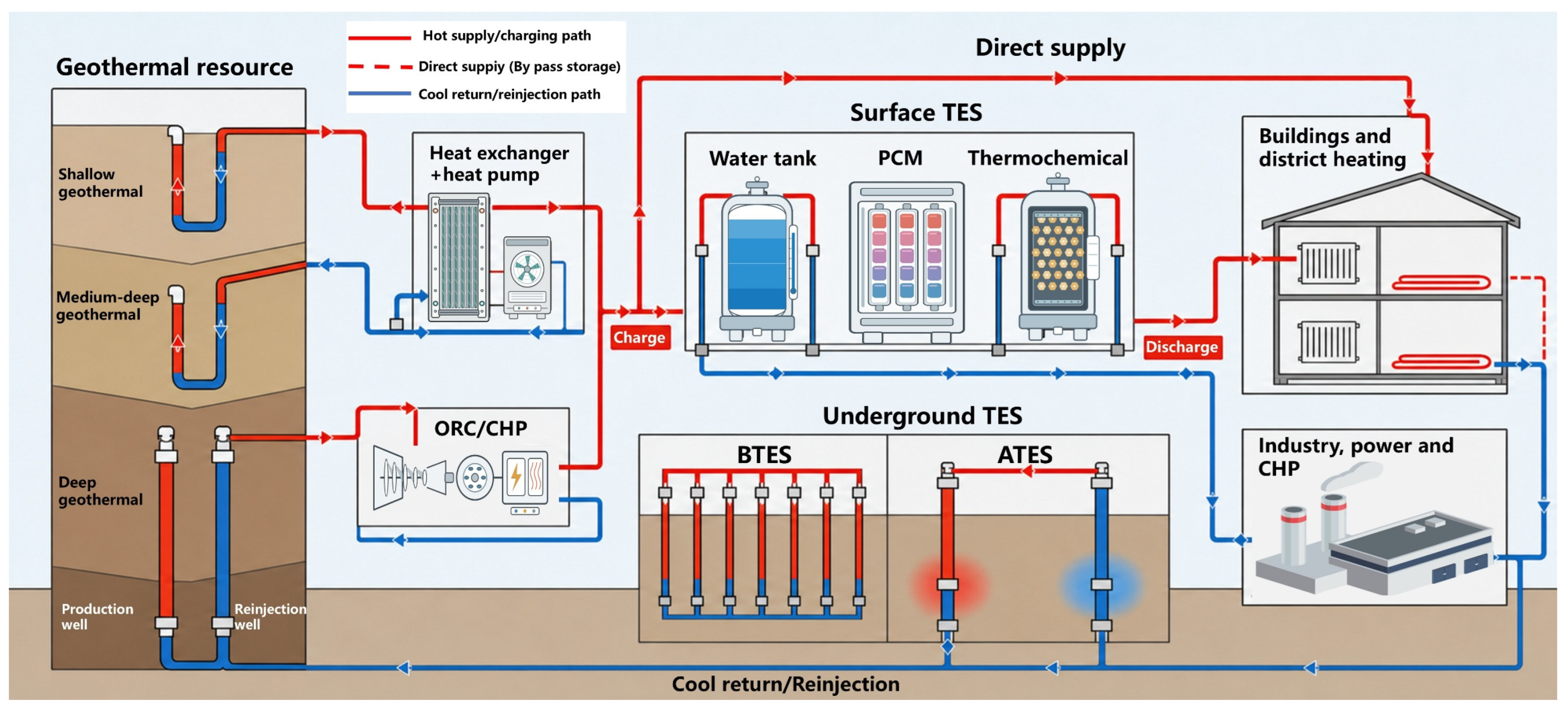
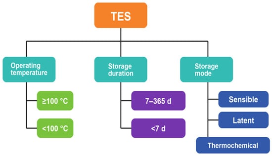
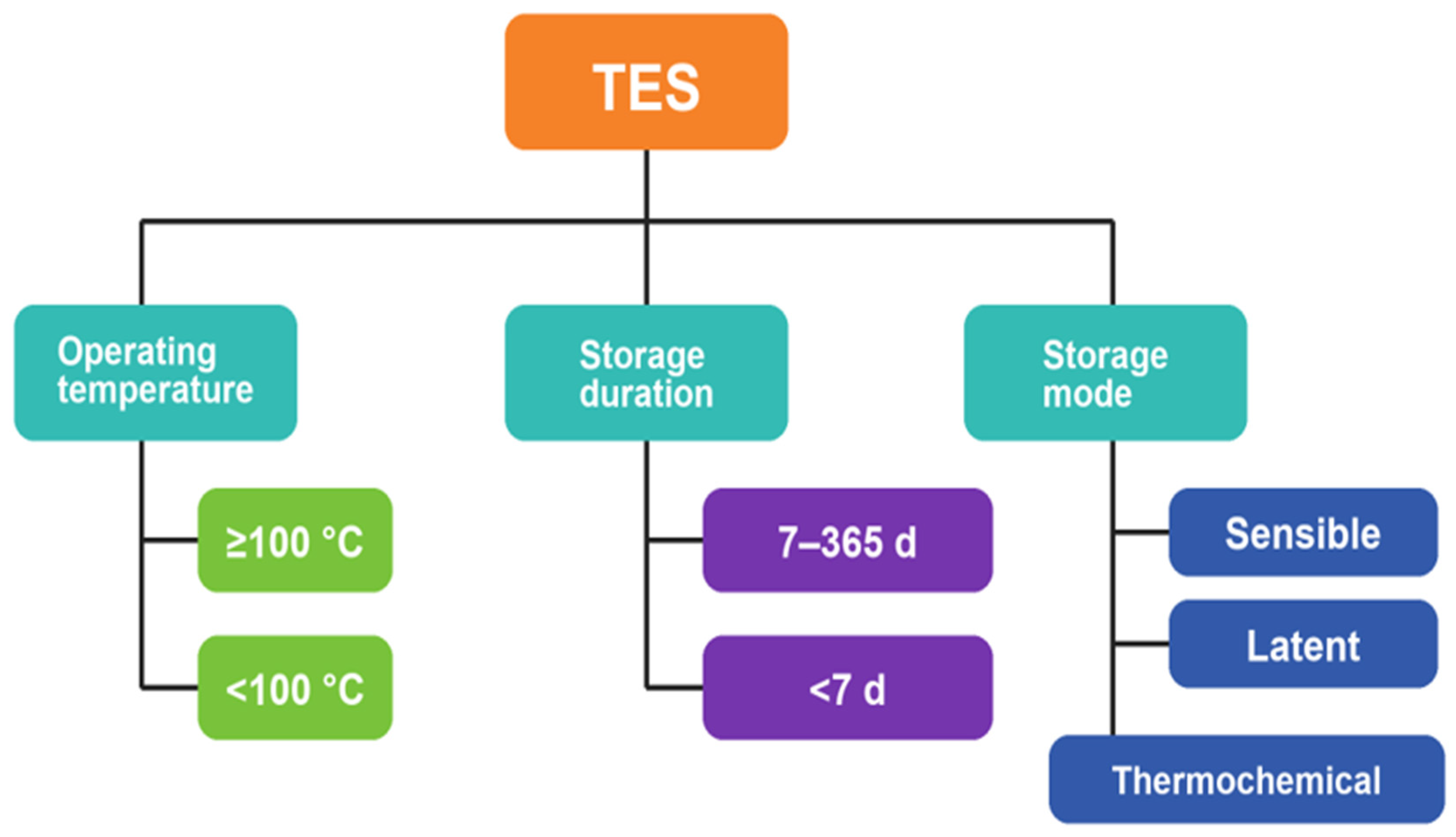
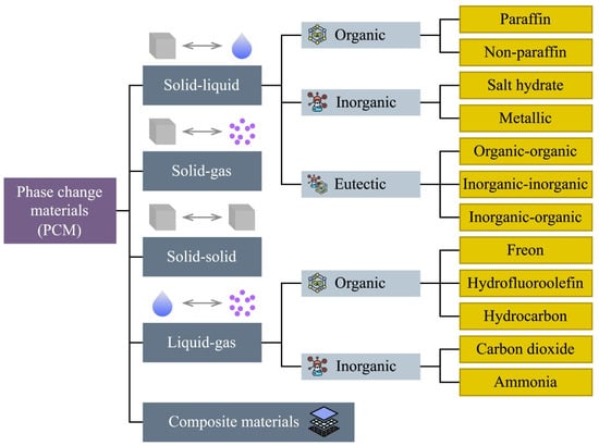
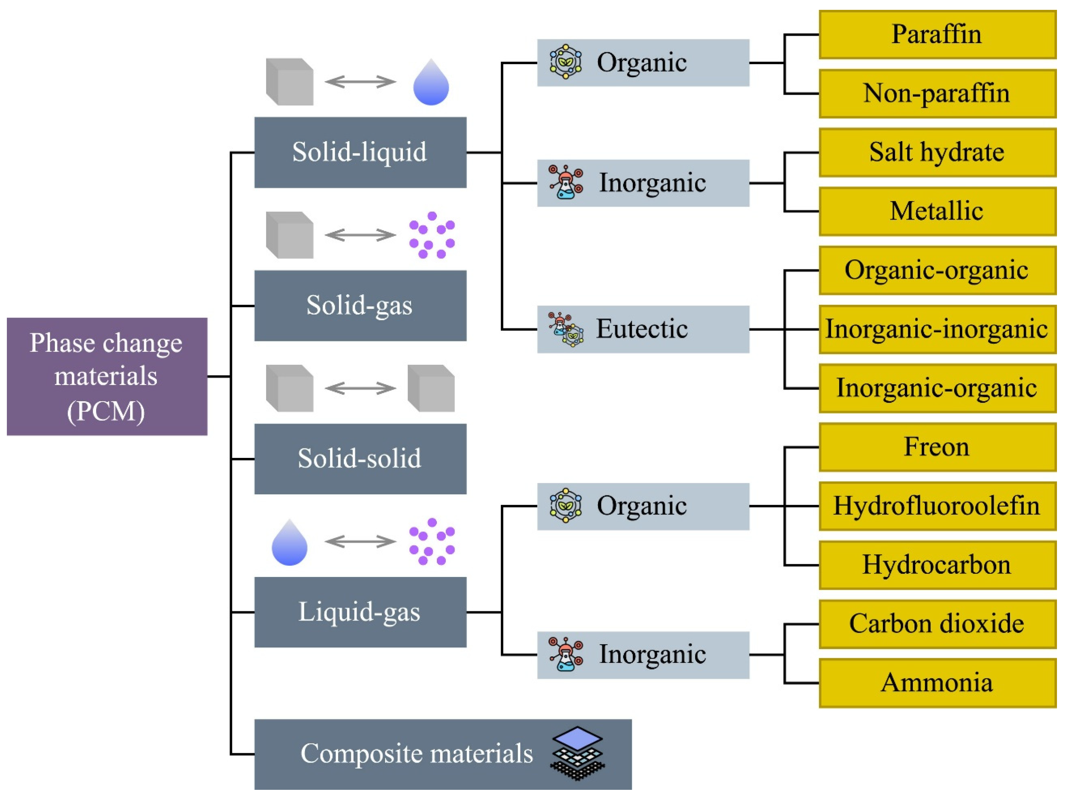
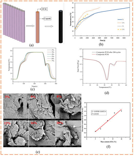
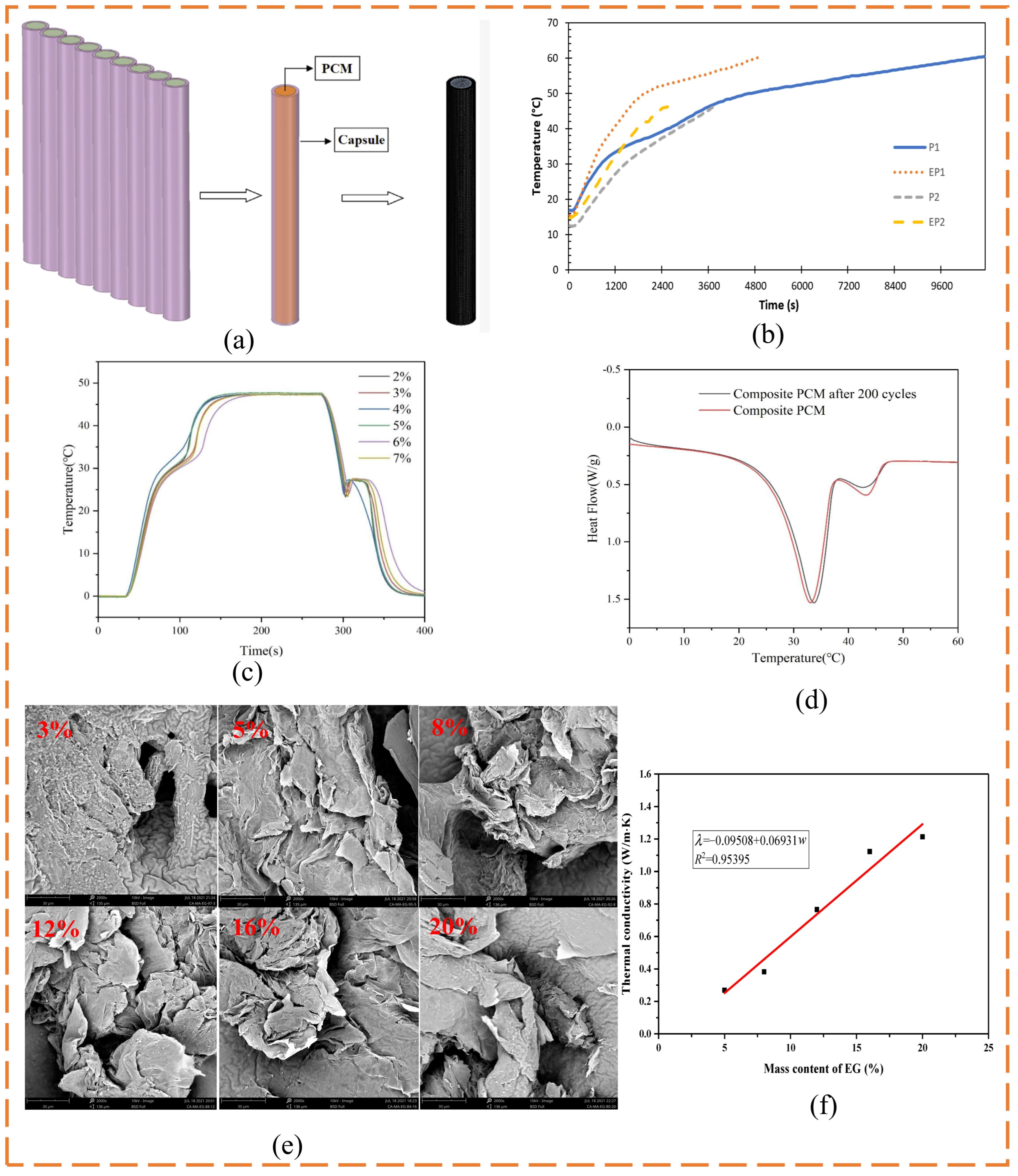
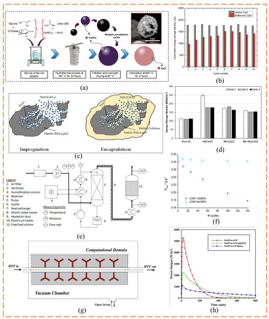
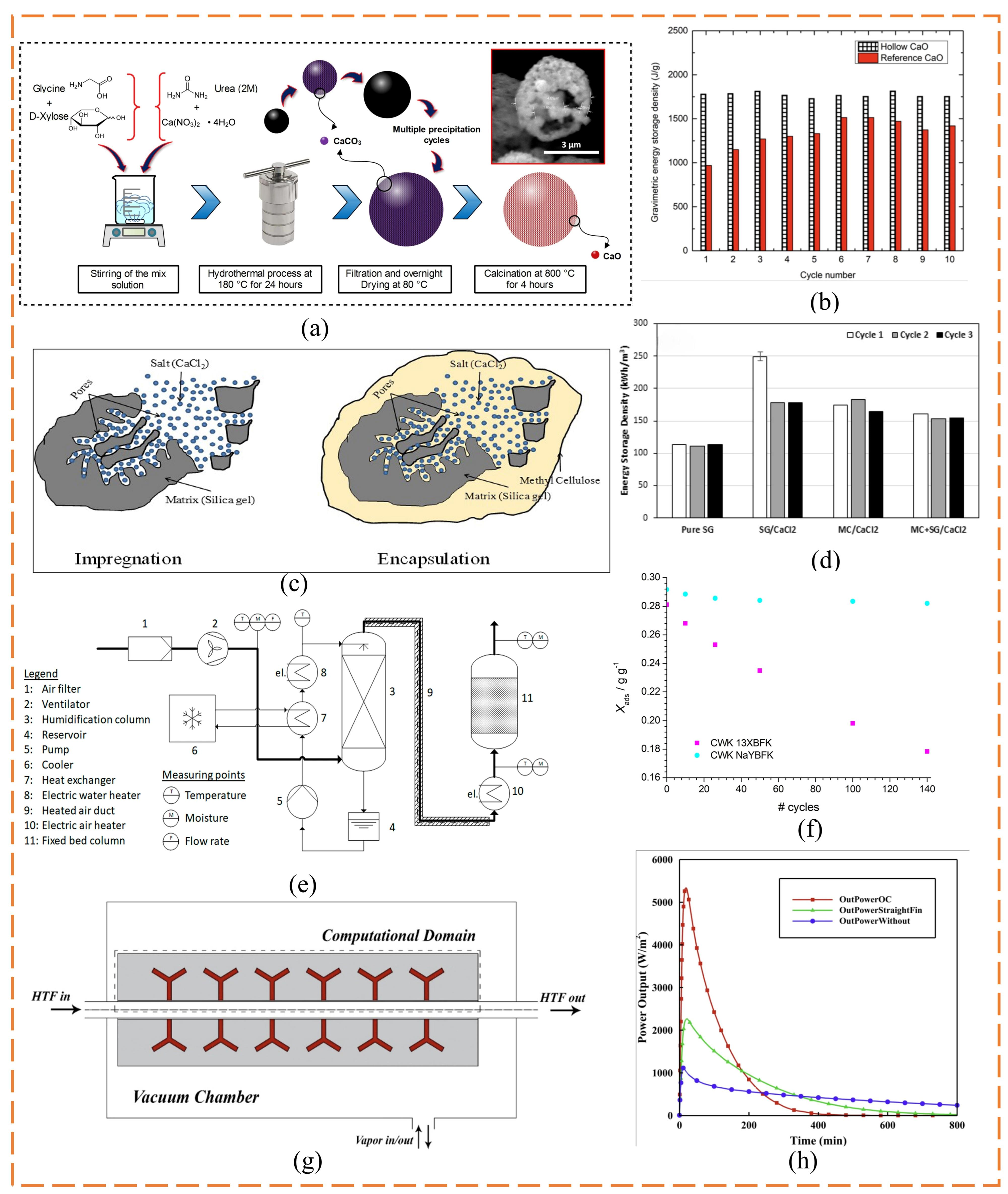
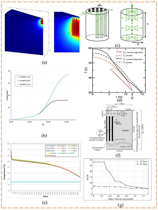
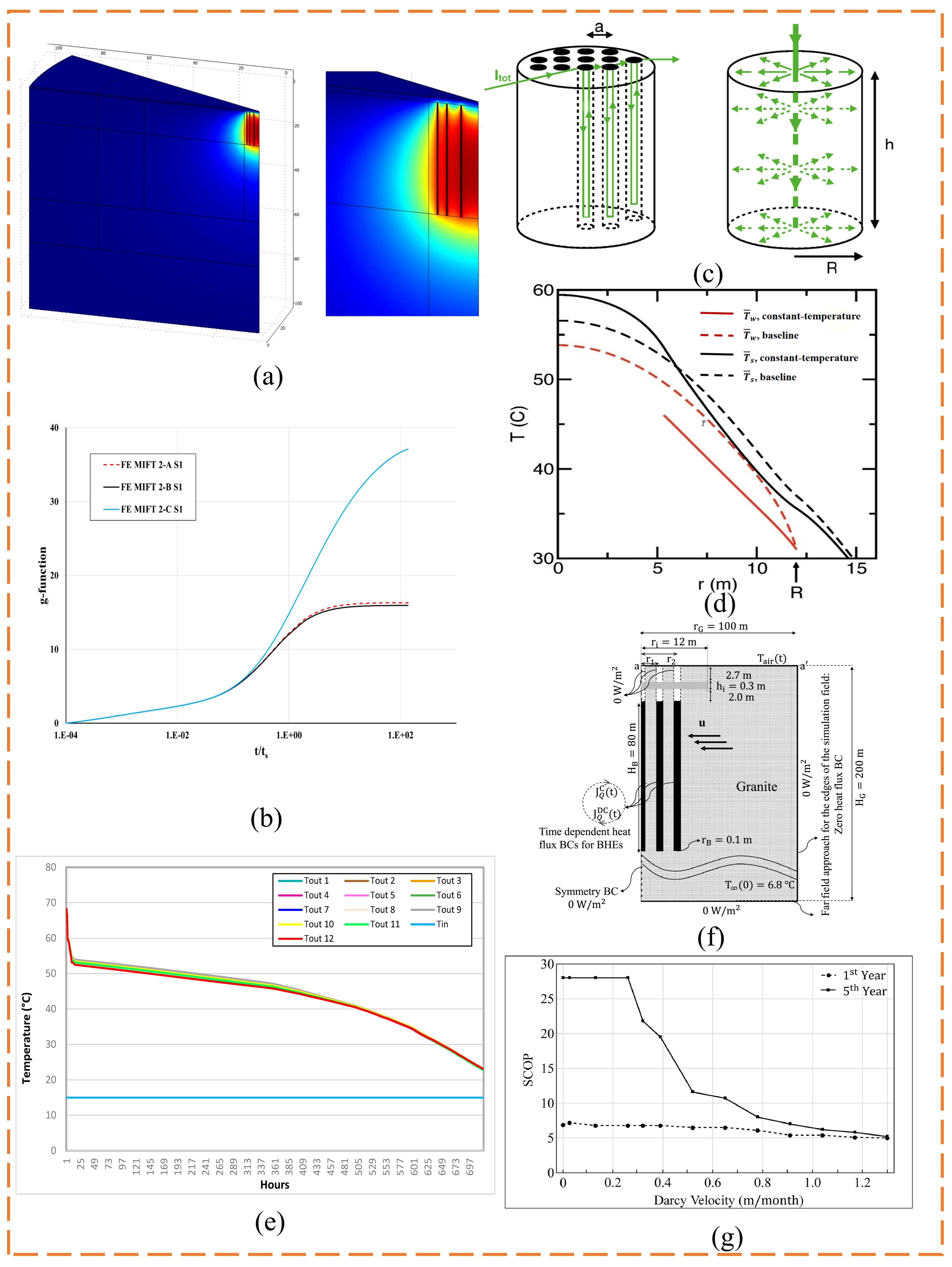
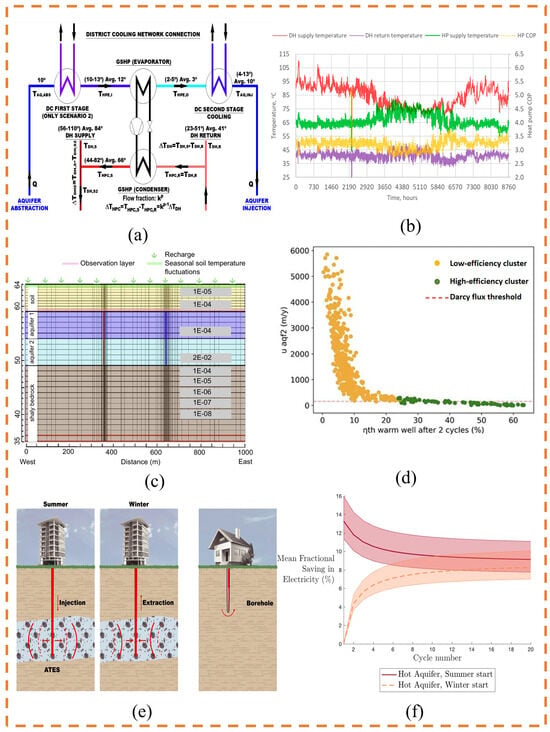
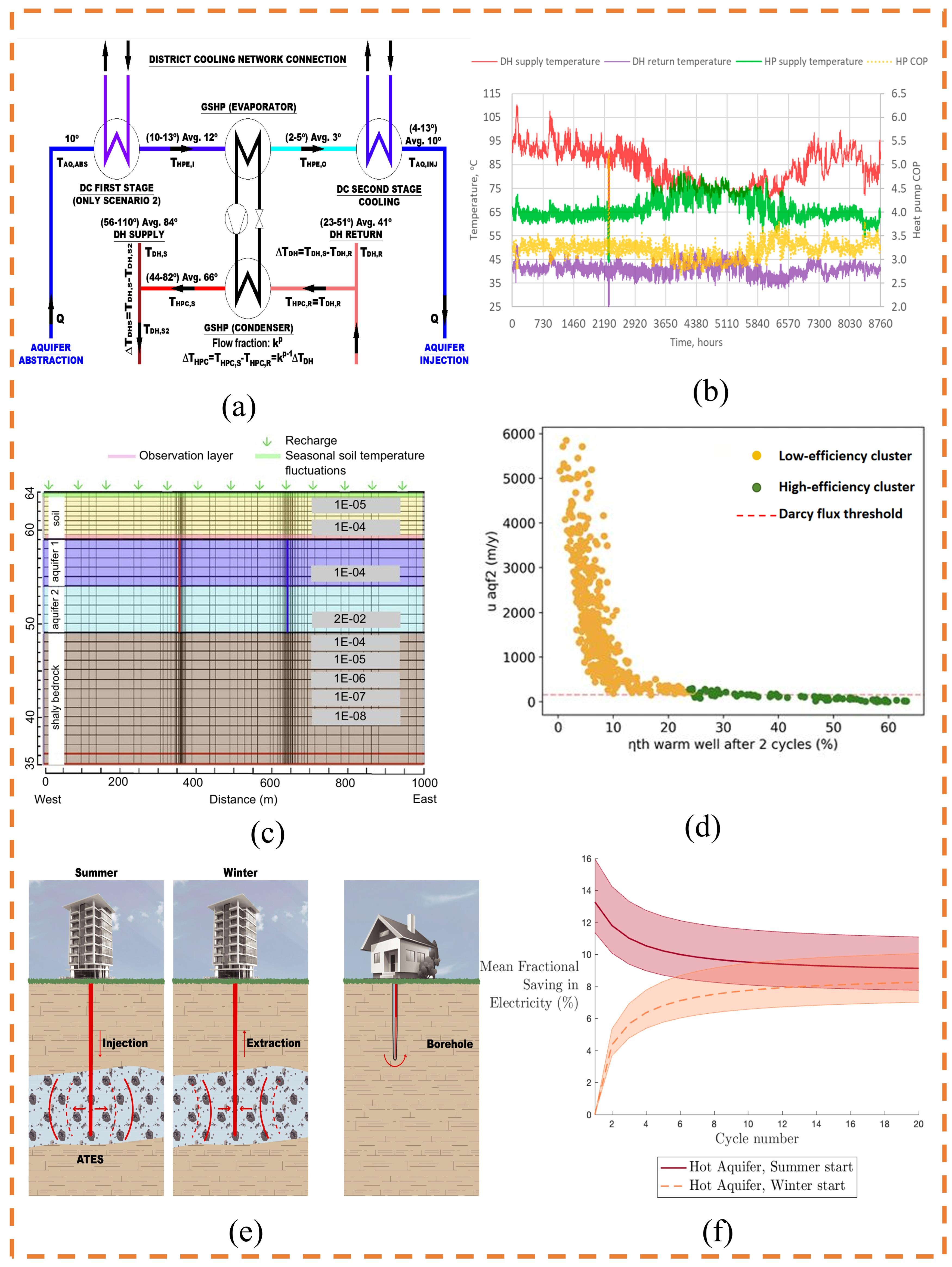
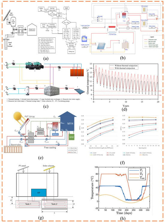
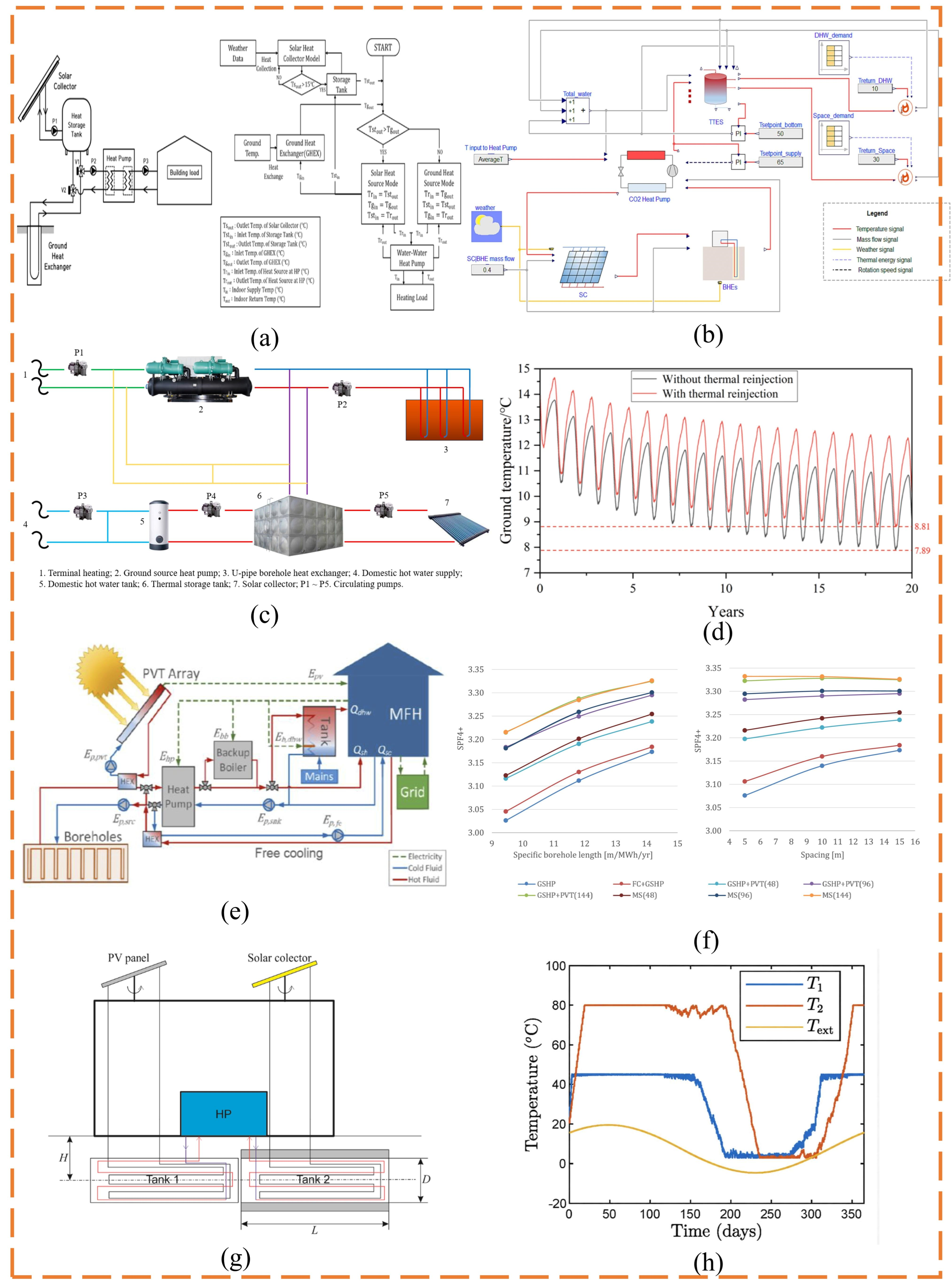

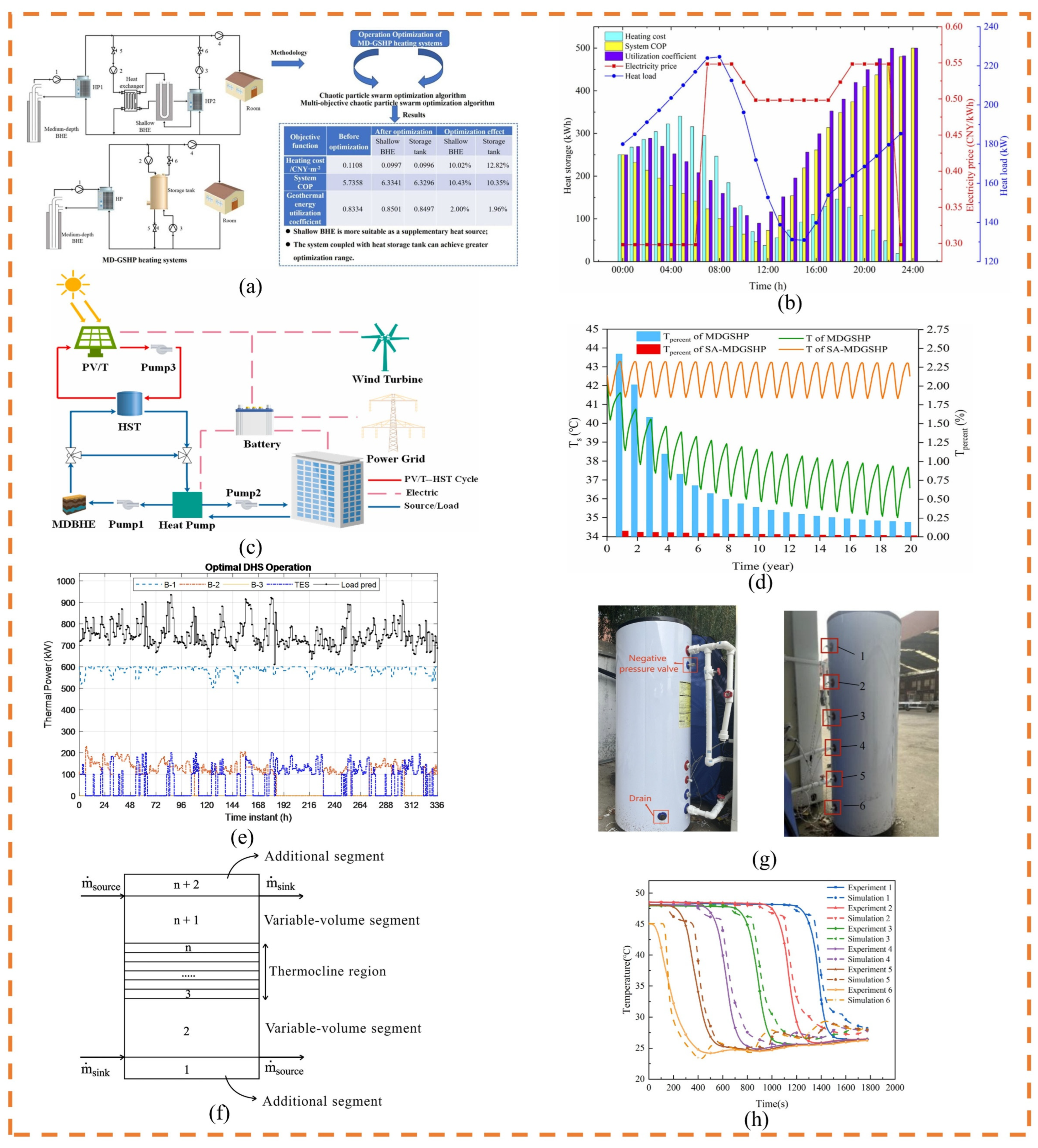
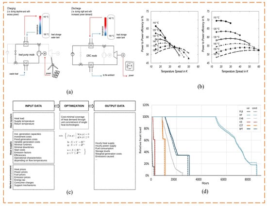
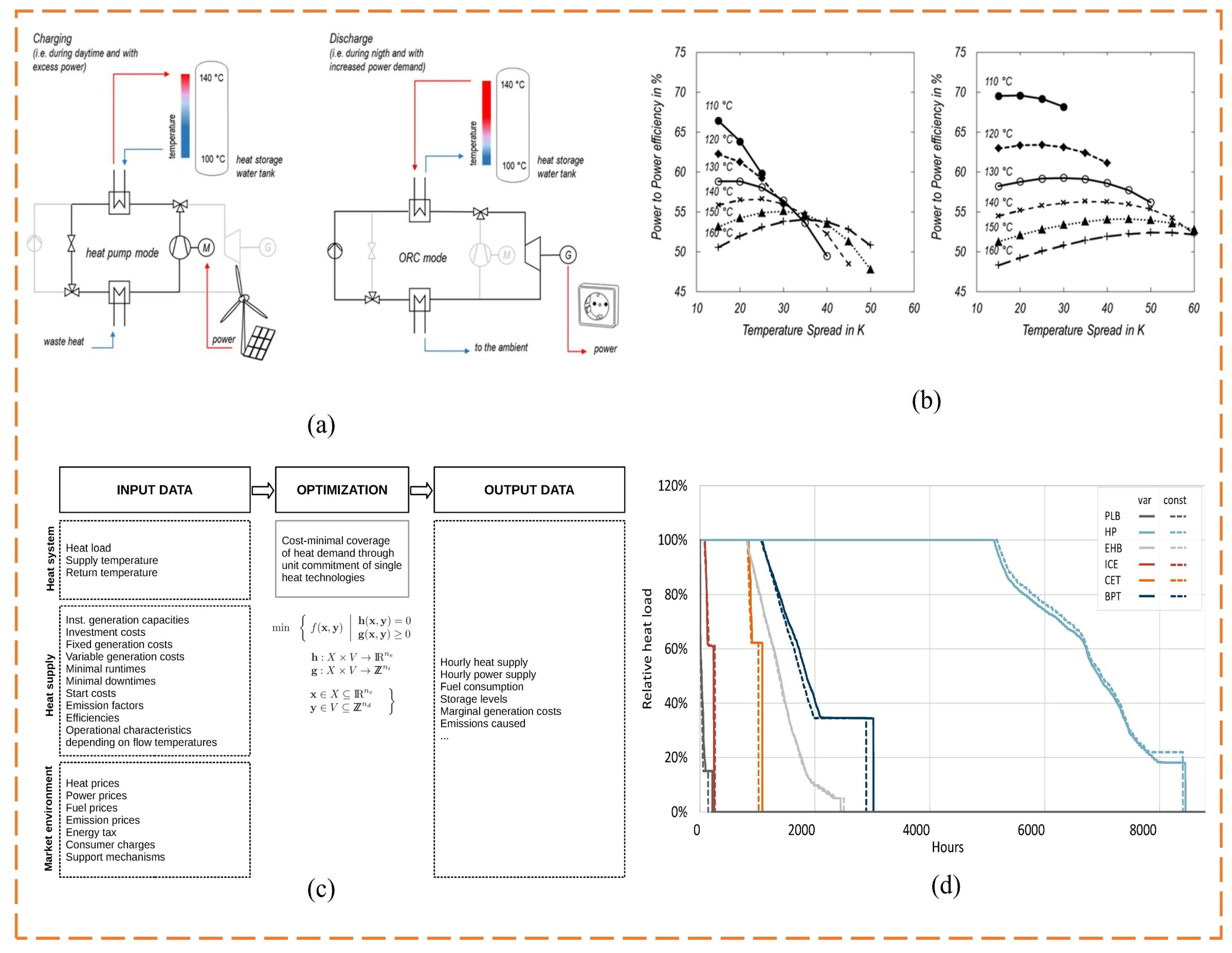
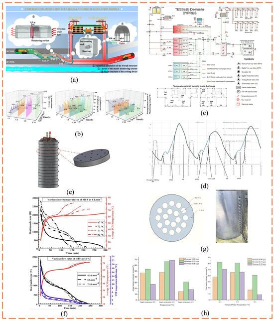
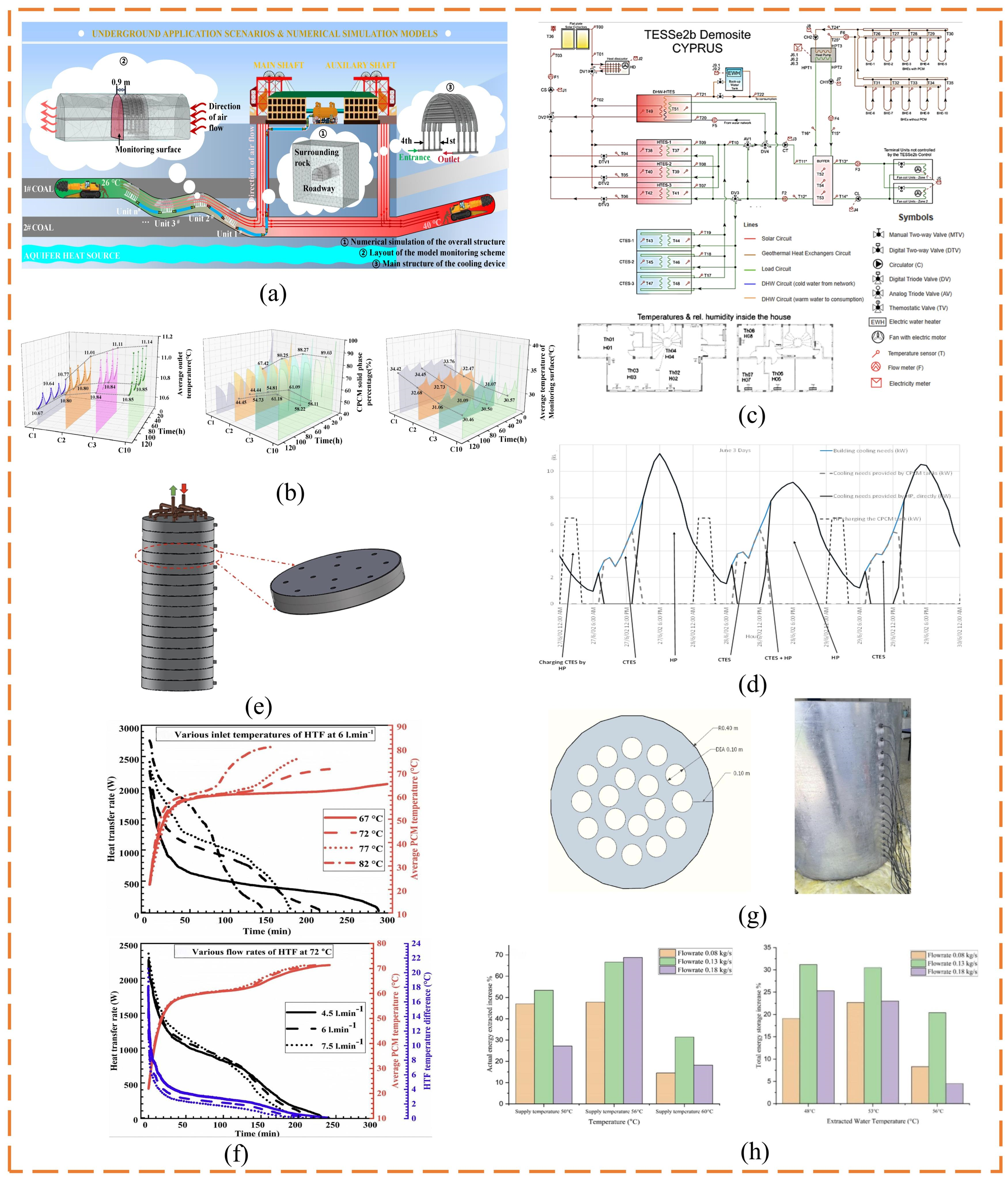
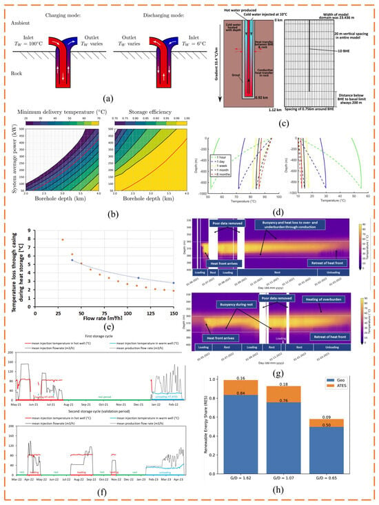
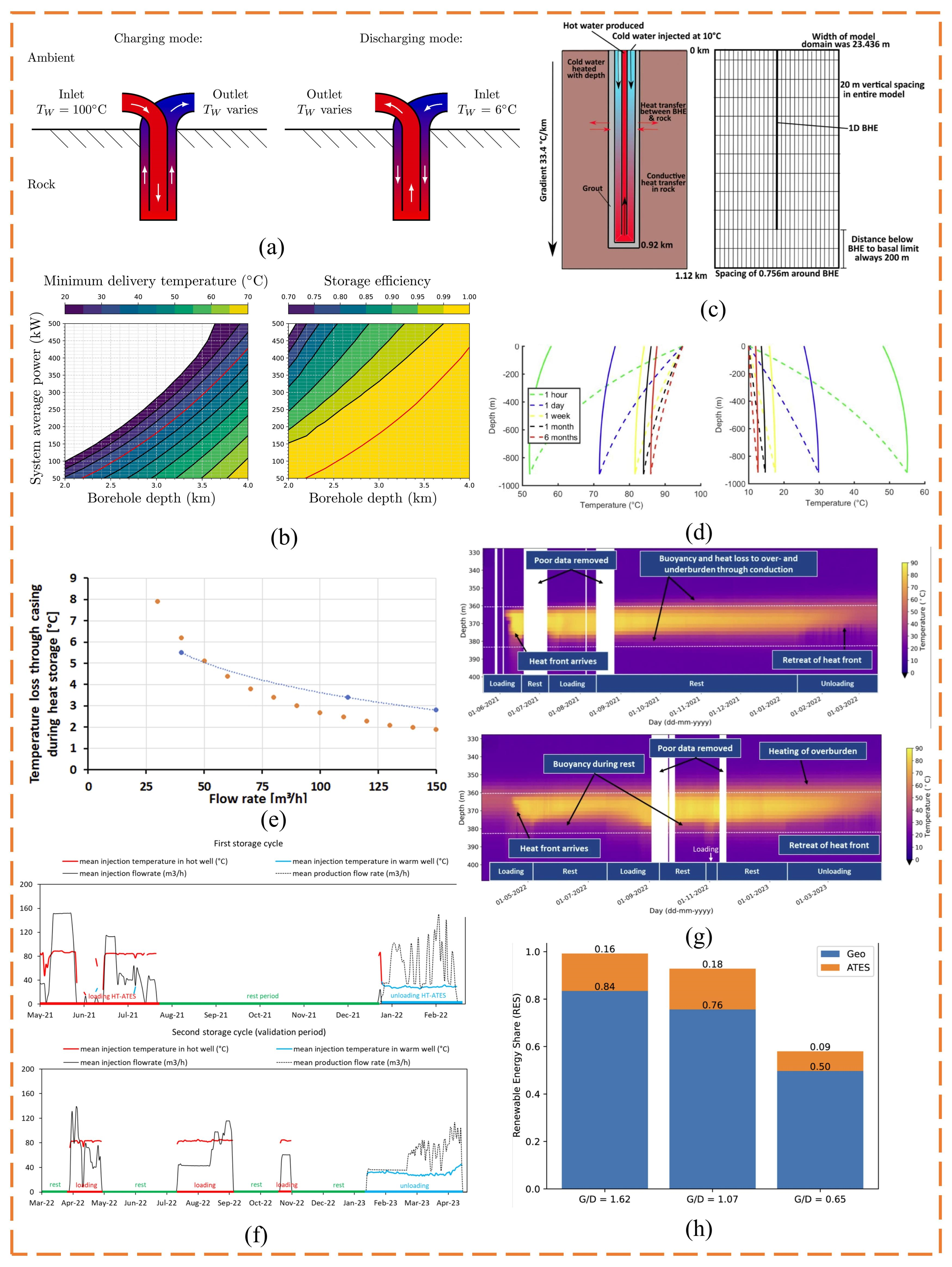
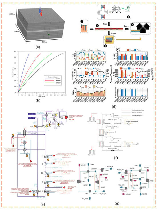
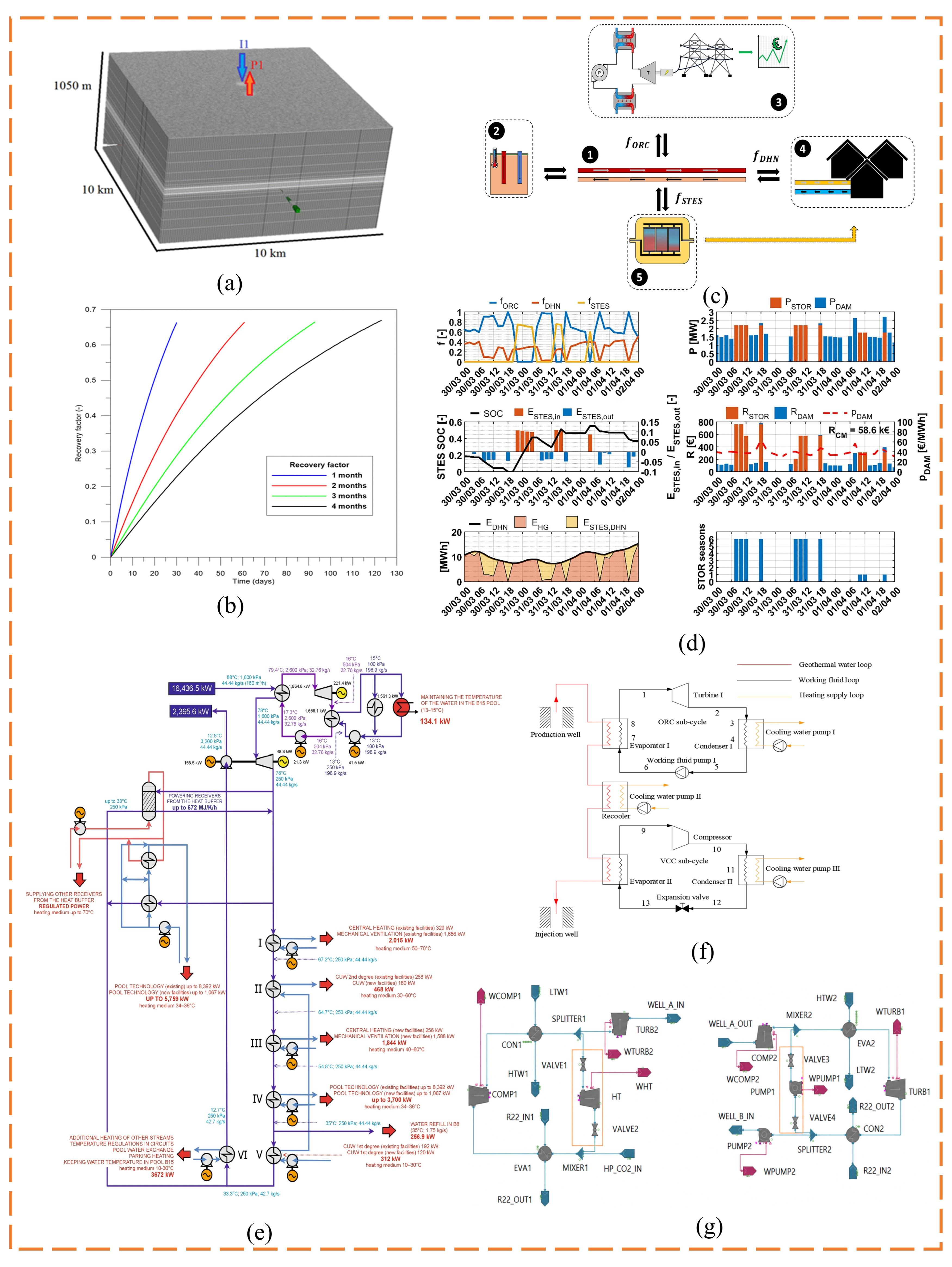

Disclaimer/Publisher’s Note: The statements, opinions and data contained in all publications are solely those of the individual author(s) and contributor(s) and not of MDPI and/or the editor(s). MDPI and/or the editor(s) disclaim responsibility for any injury to people or property resulting from any ideas, methods, instructions or products referred to in the content. |
© 2026 by the authors. Licensee MDPI, Basel, Switzerland. This article is an open access article distributed under the terms and conditions of the Creative Commons Attribution (CC BY) license.