


Abstract
This article addresses research challenges related to improving switched reluctance motor (SRM) performance, particularly for applications in electric vehicle propulsion systems and starter-generator units. The primary objective of the study is to increase energy conversion efficiency by reducing winding losses. The efficiency improvement was achieved by developing a novel stator winding topology. Conventional SRMs typically employ a double-layer concentric winding. The authors proposed two original stator winding configurations that significantly increase the fill factor. These two variants were compared with the conventional winding arrangement. Based on numerical analyses, the influence of the proposed winding topologies on the static characteristics of the SRM, as well as its performance under constant-torque and constant-power operating conditions, was investigated. The numerical results were experimentally validated using a prototype SRM equipped with the proposed stator winding configuration. Laboratory measurements confirmed the precision of the numerical predictions.
1. Introduction
The global trend toward reducing CO2 emissions has accelerated the adoption of electric motors in automotive applications. Such motors must satisfy several key requirements, including high energy conversion efficiency and a high power-to-weight ratio [1]. In practice, high-speed electric machines are used to achieve high power density while minimizing motor mass [2]. Among the available machine topologies, interior permanent magnet (IPM) motors are particularly suitable for this purpose [3]. However, the highly concentrated permanent-magnet market has stimulated interest in alternative motor technologies [4,5,6,7,8,9]. In electric vehicle drivetrains, energy conversion efficiency is a top priority parameter. The ability to operate over a wide range of constant power is the second most important parameter, commonly referred to as the second control zone [10]. Electric traction motors are typically required to achieve a constant-power-to-constant-torque ratio (CP/CT) greater than 3 [11]. Ensuring reliable operation under fault conditions is also of significant importance. Among the most severe fault scenarios are short-circuit faults, particularly those occurring within the machine [12]. Most conventional machine topologies, especially permanent-magnet machines, exhibit limited tolerance to such operating conditions. In many cases, these faults prevent further operation of the drive system. The switched reluctance motor (SRM) is one of the few types of machines capable of maintaining satisfactory efficiency, a wide operating range CP/CT, and high fault tolerance, particularly under internal short-circuit conditions [13].
Due to the potential of SRMs for the drives of electric vehicles, special attention should be paid to improving energy conversion efficiency. There are three primary methods to improve energy conversion efficiency. The first method involves reducing power losses in the motor magnetic circuit [14,15]. In the first approach, the reduction in iron losses is achieved through the use of electrical steel with lower specific core losses. This approach is particularly important in high-speed drive system applications [16]. The second approach focuses on developing an appropriate magnetic circuit shape to minimize core losses in reluctance machines [17,18]. On the contrary, the second approach focuses on modifying the geometry of the magnetic circuit itself in order to reduce core losses. In this case, the magnetic circuit is designed to minimize the magnetic flux path length, thereby reducing the losses in the core. At the same time, such an approach typically reduces the active mass of the magnetic core, particularly that of the stator. The third method aims to reduce power losses in machine windings [19,20]. According to the authors, the greatest improvement in energy conversion efficiency can be achieved by employing non-standard solutions in this area.
The novelty of this paper lies in the proposal of a new winding construction for SRMs. However, the presented solution is not the only unconventional winding design, as other non-standard winding configurations have been investigated and reported in previous studies. Two alternative winding constructions based on a double-layer concentric winding are proposed for the SRM. These solutions are compared with a conventional concentric winding configuration commonly reported in the literature [21].
The proposed winding constructions reduce losses in the SRM windings, thereby improving the efficiency of the drive system. The novel winding solutions are intended for SRMs with parallel teeth. In the analysis, various operating points along the mechanical characteristic were considered. Mathematical models of a multipole switched reluctance motor were developed. Static torque and inductance characteristics of the three design variants were analyzed. The waveforms of current, electromagnetic torque, motor losses, and efficiency were determined for several operating points. Finally, laboratory tests were performed to verify the numerical results.
2. Novel Winding Constructions for a Switched Reluctance Motor
2.1. Proposed Winding Variants for SRM
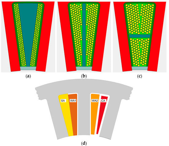
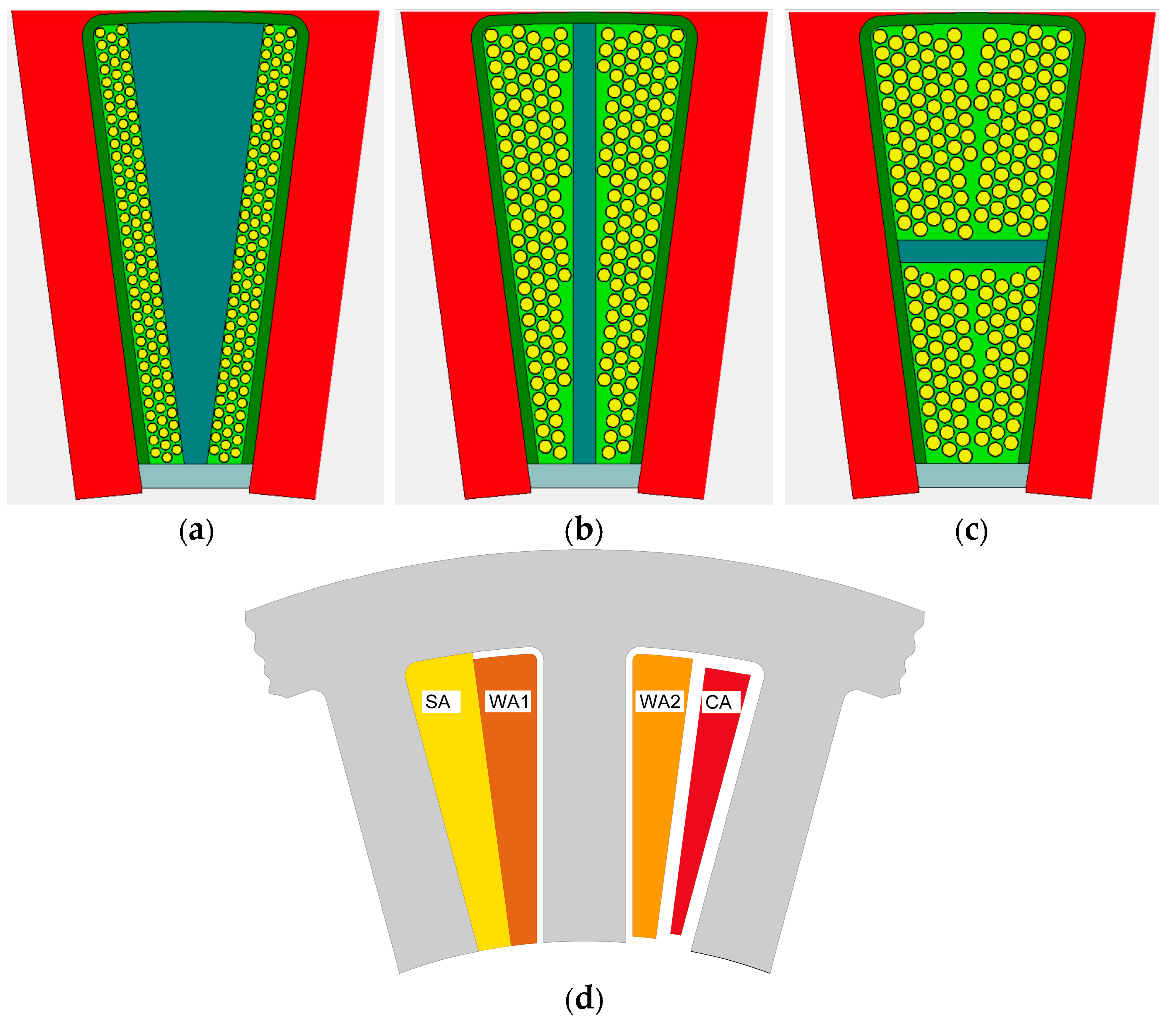
In general, reluctance machines can be classified into two main categories according to their rotor construction: machines with a cylindrical rotor (SynRM) and machines with a salient-pole rotor (SRM) [22,23]. Switched reluctance motors can be further classified according to the winding topology used, including toroidal windings (TWs) [24], single-layer distributed windings (SLDWs) [25,26,27], and concentric windings (CWs) [21]. Among these, the concentric winding is the most widely used topology in SRMs. The toroidal winding topology, although highly attractive from the perspective of reducing winding losses, is more challenging to manufacture. Single-layer distributed windings can provide a slightly higher electromagnetic torque capability. However, the longer end-winding connections increase copper losses, which consequently reduces the overall efficiency of the drive system. The stator winding consists of a set of coils, each wrapped around a single stator pole [21]. A conventional SRM winding employs a double-layer trapezoidal side-by-side winding (DLTS/SW), as shown in Figure 1a. This winding arrangement is typically adopted when the machine is wound manually. In the event of winding damage, replacement of an individual coil is generally not feasible and often requires rewinding the entire stator winding. To facilitate partial winding replacement, a double-layer V-shaped side-by-side winding (DLVS/SW), shown in Figure 1b, may be used. Both winding topologies are also used in selected brushless permanent-magnet machines (BLPMMs). In BLPMMs, double-layer upper/lower windings (DLU/LWs), shown in Figure 1c, are also employed. However, to the best of the authors’ knowledge, this winding arrangement has not previously been applied in SRMs.
Figure 1.
Typical DL winding configurations used in BLPMMs: (a) DLVS/SW, (b) DLTS/SW, (c) DLU/LW, (d) designation of the slot fill factor definitions available for implementation.
Figure 1 illustrates the three double-layer winding configurations commonly used in BLPMMs.
When analyzing the use of the slot space in electrical machines, three coefficients are generally used. These are: wire slot fill—winding area (WSF1), wire slot fill—slot area (WSF2), and copper slot fill (CSF). They are defined as follows:
where: WA1—winding area + wedge area + coil divider area; WA2—winding area; SA—slot area; and CA—copper area (Figure 1d).
Typical values of the WSF and CSF for common double-layer winding configurations are given in Table 1. However, these values are influenced by several design factors, including the type of insulation of the recessed hole, the thickness of the insulation, and the geometry of the coil separator.
Table 1.
Typical values of WSF and CSF for the windings in Figure 1.
The DLVS/SW topology exhibits relatively low slot utilization. A higher degree of slot utilization can be achieved with the DLTS/SW topology. Both configurations are used in SRM, although the DLTS/SW arrangement is more prevalent in practical applications [21]. The DLU/LW topology provides substantially greater design flexibility and improved slot utilization. However, this winding configuration has not yet been reported for SRM applications.
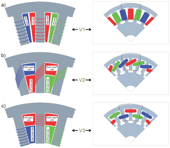
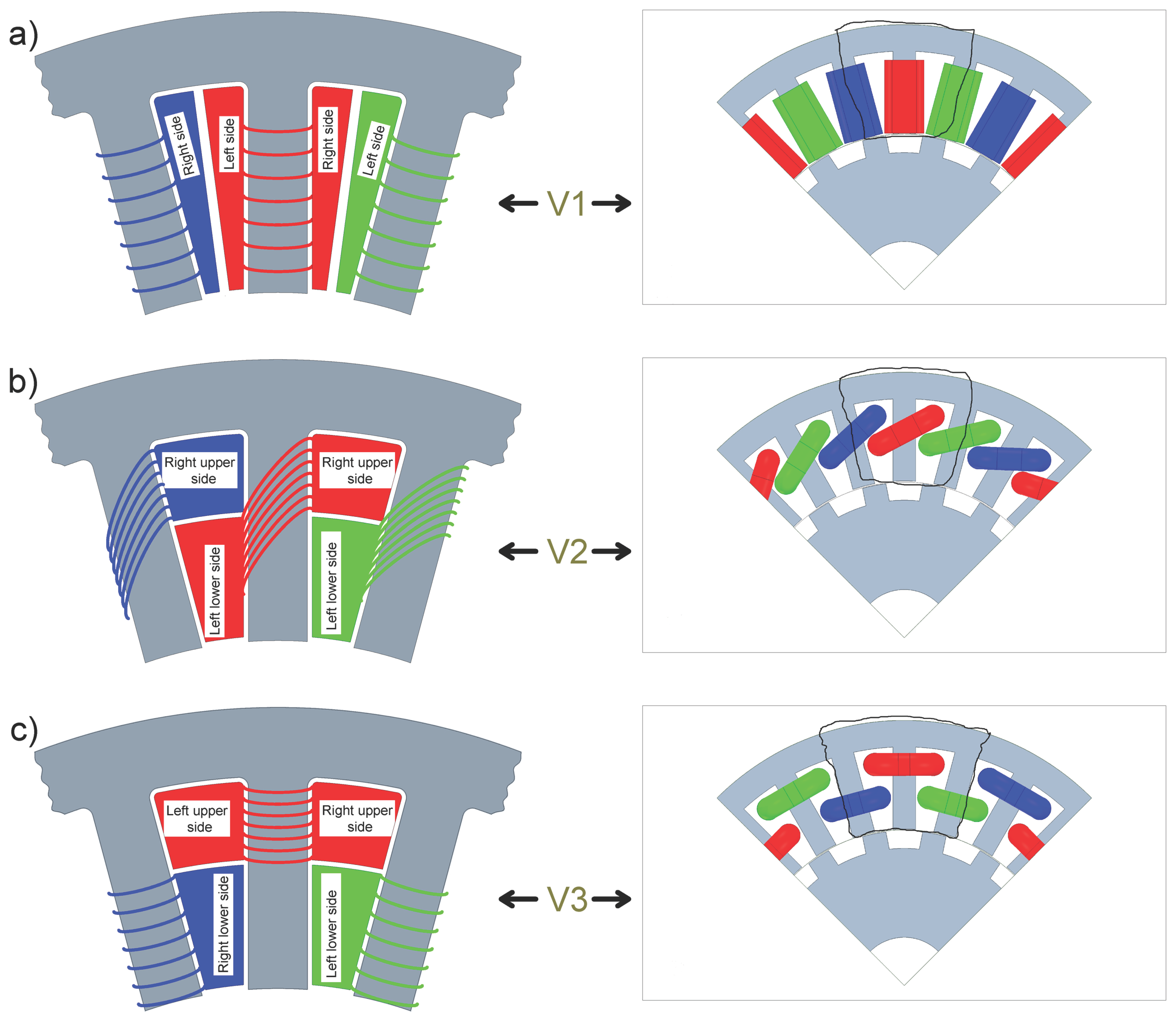
Figure 2a illustrates the conventional DLTS/SW configuration. The proposed winding variants, denoted V2 and V3, are shown in Figure 2b and Figure 2c, respectively. Both configurations are derived from the DLU/LW topology presented in Figure 1c.
Figure 2.
SRM winding configurations: (a) typical slot space filling for V1, (b) novel slot space filling for V2, (c) novel slot space filling for V3.
The TW is particularly sensitive to magnetic saturation in the stator yoke and makes motor manufacturing and assembly more challenging. On the contrary, the SLDW requires relatively long end-winding connections. However, it enables more effective use of the available slot area. Therefore, efforts to improve the energy conversion efficiency of SRMs should focus on achieving more efficient utilization of the available slot area (SA). Such opportunities are provided by the DLU/LW-based winding configurations proposed by the authors, as illustrated in Figure 2b,c.
At the motor design stage, each designer must solve the problem of having a lot of space for placing the motor coils. In a typical design process for a conventional machine, the typical WSF1 ranges from 60% to 66% (the space factor of an insulated wire in a free slot) [28]. Obtaining such a coefficient is possible in typical AC machines with distributed SL and DL windings. The DLTS/SW SRM winding is shown in Figure 2a, and this variant is denoted as V1. Unfortunately, achieving a WSF1 of 60% is not possible with this winding method. From practical experience, the typical WSF2 for the DLTS/SW SRM winding is approximately 50%. This introduces significant limitations in the design process when increasing the cross-section of the winding wire. The authors propose a significant modification of the SRM winding method by changing from DLTS/SW (Figure 2a) to DLU/LW (Figure 2b,c). The slot pitch of the DL winding in an SRM is limited to 1. The original concept proposed by the authors is the implementation of the DLU/LW in the form shown in Figure 2b (Variant V2). Another option is the two-level double-layer winding (TLDLW) shown in Figure 2c (Variant V3). Both proposed solutions, i.e., DLU/LW (Figure 2b) and TLDLW (Figure 2c), provide maximum utilization of the slot space in SRMs with parallel teeth.
The V1 structure is a classic SRM winding. This winding is arranged on both sides of the pole [Figure 2a]. The V1 construction is characterized by the shortest end connections and introduces relatively small values of end-connection inductance. At the same time, it is characterized by the lowest utilization rate of slot space (Figure 2a). The proposed V2 construction is a typical two-layer winding with minimal pitch (e.g., the left lower side and the right upper side) (Figure 2b). This winding method is characterized by relatively long winding end connections and the highest value of end-connection inductance. These drawbacks are compensated for by a much greater use of slot space compared to the classic V1 variant. In the V3 construction, the windings are arranged on two levels (Figure 2c). This means that alternating windings are arranged, for example, in the form of the left upper side and the right upper side (Figure 2c), and so on. The V3 variant uses the slot space in the same way as the V2 variant. Similarly, it offers slightly shorter end-connection lengths and lower end-connection inductances. However, these differences are not significant. The V2 and V3 winding structures are proprietary solutions for SRMs. Table 2 presents comparison of the available slot space for the design variants.
Table 2.
Comparison of the available slot space for the design variants.
The V2 and V3 variants are typical of classic AC machine windings and allow the use of winding wire with a larger diameter. In both cases, the utilization of WSF1 is very similar and is equal to 60%. The V3 variant is the most advantageous in terms of the potential reduction in winding losses due to its slightly shorter end connections. Theoretically, this reduces copper losses by more than 22% compared to the classic V1 variant (assuming Irms = const).
When analyzing the proposed solutions, the issues of practical feasibility and reliability are also important. Only the solution shown in Figure 1a allows the replacement of damaged windings on a single pole. For V2, it is not possible to replace a single damaged winding. In the case of V3, only the lower pole windings can be easily replaced. Replacing the upper pole winding is possible but requires the removal of two adjacent lower pole windings. In the case of the classic V1 solution, the use of WSF1 as shown in Table 1 makes it very difficult to replace a single damaged pole winding. According to the authors, in practice there is a high probability of damage to the insulation of the adjacent windings. In the case of V2 and V3, additional interlayer insulation must be used. It can also be assumed that an improvement in efficiency simultaneously has a negative impact on the reliability of the drive system. This is due to the reduction in the distance between adjacent windings, such as those of different phases.
2.2. Power Supply Configuration for SRM Winding Variants
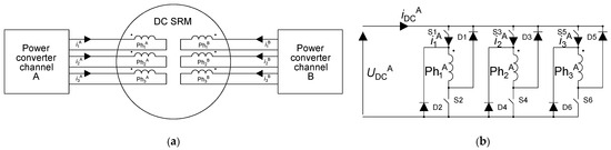
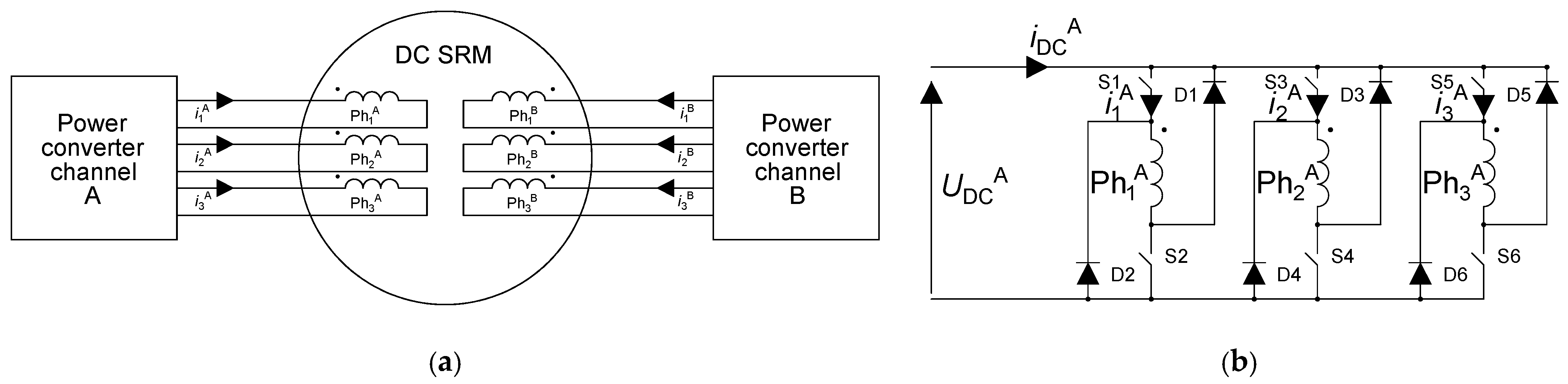
SRM structures are frequently designed for use in drives requiring high reliability. The use of a multipole design gives the SRM construction much greater tolerance to emergency operating conditions. In the case of a multipole SRM design, it is relatively easy to adapt the machine to a multichannel power supply, e.g., a four-channel or dual-channel configuration. Figure 3a shows an example of a two-channel SRM configuration. The power converter for reference Channel A of the SRM is shown in Figure 3b.
Figure 3.
(a) Example of a two-channel SRM configuration; (b) power converter for reference channel A of the SRM.
The SRM multichannel power supply allows a significant increase in the level of redundancy of the drive system [29]. Three constructions have been designed, denoted V1, V2, and V3. For practical implementation, the V3 variant was selected due to its lowest copper losses.
Table 3 lists the common parameters of the SRM constructions.
Table 3.
Parameters of the constructions analyzed.
Table 4 contains the estimated values of the phase resistances for the individual variants, assuming that all channels of each phase are connected in parallel (four branches per phase). The resistance of a single pole winding was estimated by considering the active lengths of both conductor sides and the end-winding connections. For each winding configuration considered, the average end-winding length was calculated. The winding data for each variant are given in Table 4.
Table 4.
Estimated phase/pole resistance for analyzed design variants at 20 °C.
A change in the use of the stator slot affects more than just the motor resistance (Table 4). It also changes the copper mass and the machine manufacturing costs. For the conventional V1 variant, the total copper mass is 2.2 kg, while the total motor mass is 19.5 kg. In the case of the V2 and V3 variants, the copper mass increases to approximately 2.6 kg, whereas the total motor mass is 19.9 kg. Assuming a wholesale copper price of approximately 14 USD/kg, the additional copper required in the V2 and V3 variants increases the manufacturing cost by approximately 5.6 USD per machine. When considering the observed improvement in efficiency and reduction in winding losses, this increase in material cost appears to be justified.
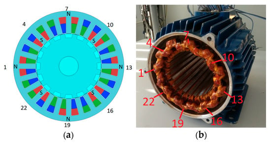
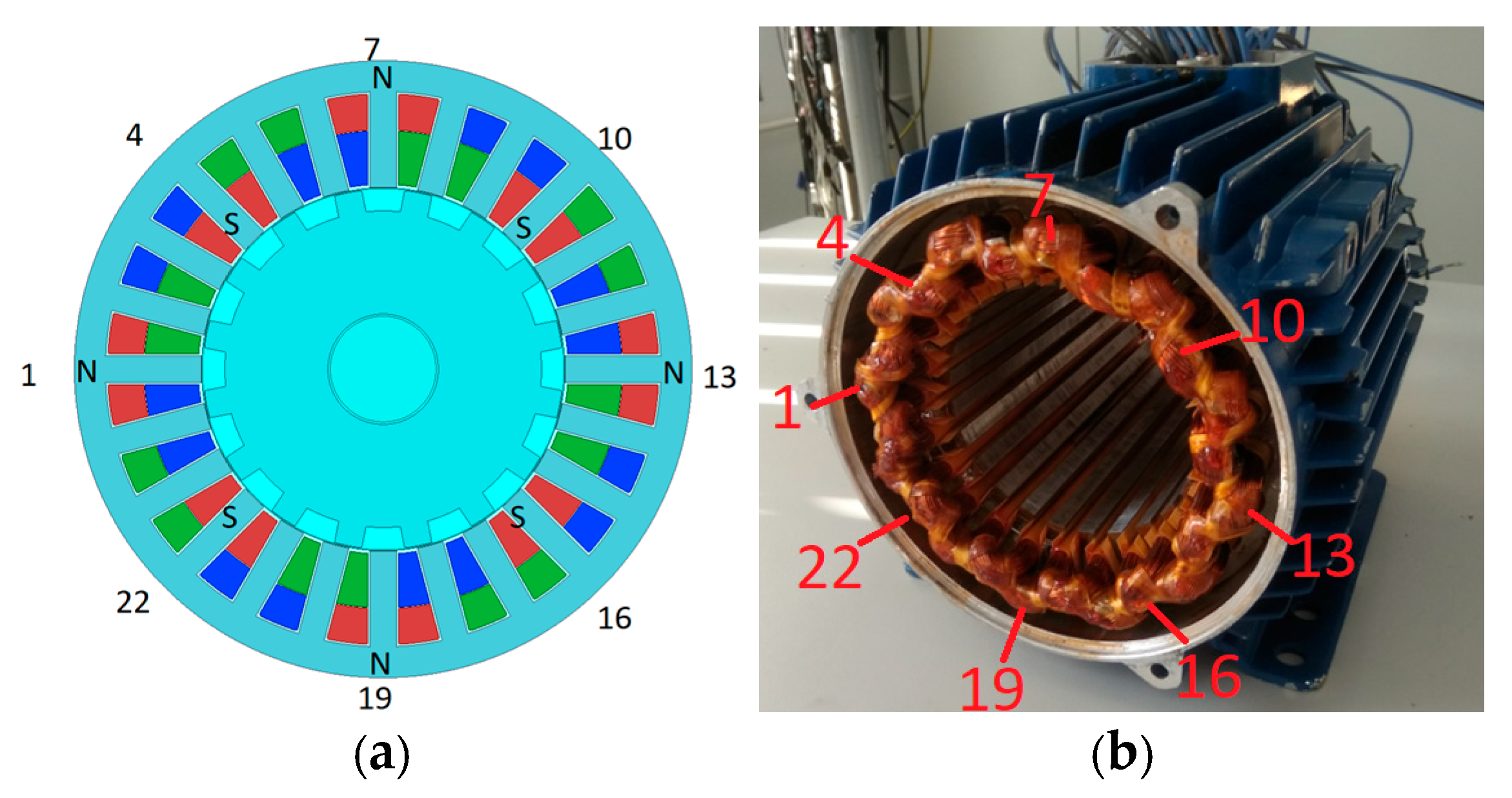
Figure 4a presents the cross-sectional view of the V3 variant, with the poles of the conventional Ph1 phase indicated. The prototype stator is shown in Figure 4b, together with the TLDLW arrangement employed in the design.
Figure 4.
Variant V3: (a) multipole SRM cross-section; (b) SRM’s stator prototype with TLDLW.
All constructions analyzed have eight stator poles per phase (two stator poles per channel). This allows the use of a different method of pole supply for the phase [30]. In the case of Phase 1, the pole pairs 1 and 4, 7 and 10, 13 and 16, and 19 and 22 form channels (branches) A, B, C, and D, respectively (Figure 4a). The paper analyzes windings with parallel-connected branches (four parallel branches in each phase). The article uses the NSNSNSNS type of power supply (Figure 4a). In this power supply method, the adjacent poles of one phase are unlike poles. This allows full symmetry of the mutual magnetic couplings [30,31]. This has a positive influence on motor operation under conventional power supply conditions.
3. Mathematical Model of the Three-Phase SRM
A mathematical model of a three-phase SRM developed by the authors is presented. In three-phase SRM machines with nonlinearity of the magnetic circuit, the phase flux-linkages ψk = ψk(i1,i2,i3,θ) (k ∈ (1,2,3)—stator phase number) depends on the phase currents i1, i2, i3 and the electrical rotor position angle θ. The general structure of the mathematical model of a three-phase SRM can be expressed as follows:
where Te is the electromagnetic torque. The following symbols are defined for (4)–(6): uk—phase voltages, k ∈ (1,2,3); Rk—phase resistances, k ∈ (1,2,3); ω—the rotational speed; J—total rotor moment of inertia; D—rotor damping of viscous friction coefficient; TL—load torque; and —total magnetic field co-energy in the machine air gap.
In the general case of the motor construction, it can be assumed that the main flux of each motor phase is non-linear according to the relation:
where ψkk(ik,θ)—self phase flux-linkages, k ∈ (1,2,3); ψkl(ik,il,θ)—mutual fluxes k ≠ l ∈ (1,2,3). The total electromagnetic torque given by (5) can be expressed as the sum of the self-torque and the mutual torque:
Equations (4)–(6), together with (7) and (8), constitute the classical mathematical model of the SRM with nonlinear magnetic flux. However, this model is too complex for practical applications. Depending on the simplified assumptions adopted, a novel nonlinear flux–inductance model, developed by the authors, can be formulated.
For the motor configuration considered, it is assumed that the main flux linkage of each phase is nonlinear, whereas the mutual flux linkages associated with a given phase and generated by currents in the remaining phases depend linearly on these currents, as:
where Lkl(θ)—coefficients only mutual inductances, k ≠ l ∈ (1,2,3). The electromagnetic torque in (5) can be expressed as:
Equations (4)–(6), together with (9) and (10), constitute a mathematical model of the SRM based on non-linear main flux links and linear mutual inductances. In special cases of the proposed model, the mutual inductances may be assumed to be constant Lkl(θ) = const or, in the simplest case, negligible (i.e., equal to zero Lkl(θ) = 0). Consequently, the electromagnetic torque given by (10) reduces to its first term.
The finite element method (FEM) is employed to determine the phase flux linkages and the mutual inductances of the SRM. The proposed mixed flux–inductance model represented by (4)–(6), (9) and (10) offers a compromise between estimation accuracy and computational complexity in applications such as electromagnetic torque estimation.
4. Analysis of Static Characteristics for SRM Winding Variants
4.1. Numerical Setup
The numerical model was developed using a commercial finite element analysis software package [32]. Particular attention was paid to the mesh density within the air gap between the stator and rotor. An additional parameter of importance was the number of finite elements distributed along the diameter at the air-gap midline. This parameter should be determined individually for each machine geometry, as it depends on the number of rotor poles. An increase in the number of rotor poles requires a corresponding increase in the number of finite elements along the circumference at the air-gap midline to ensure adequate solution accuracy.
A transient analysis was used to investigate the static operating conditions. It was assumed that a rotor rotational speed of 1°/s was low to neglect transient effects. In the case analyzed, the minimum rotor step size was set at 0.125°. This resolution provided 180 calculation points per electrical period.
4.2. Flux Linkage and Inductance Characteristics
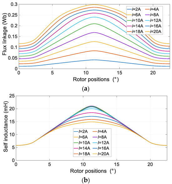
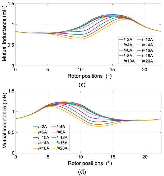
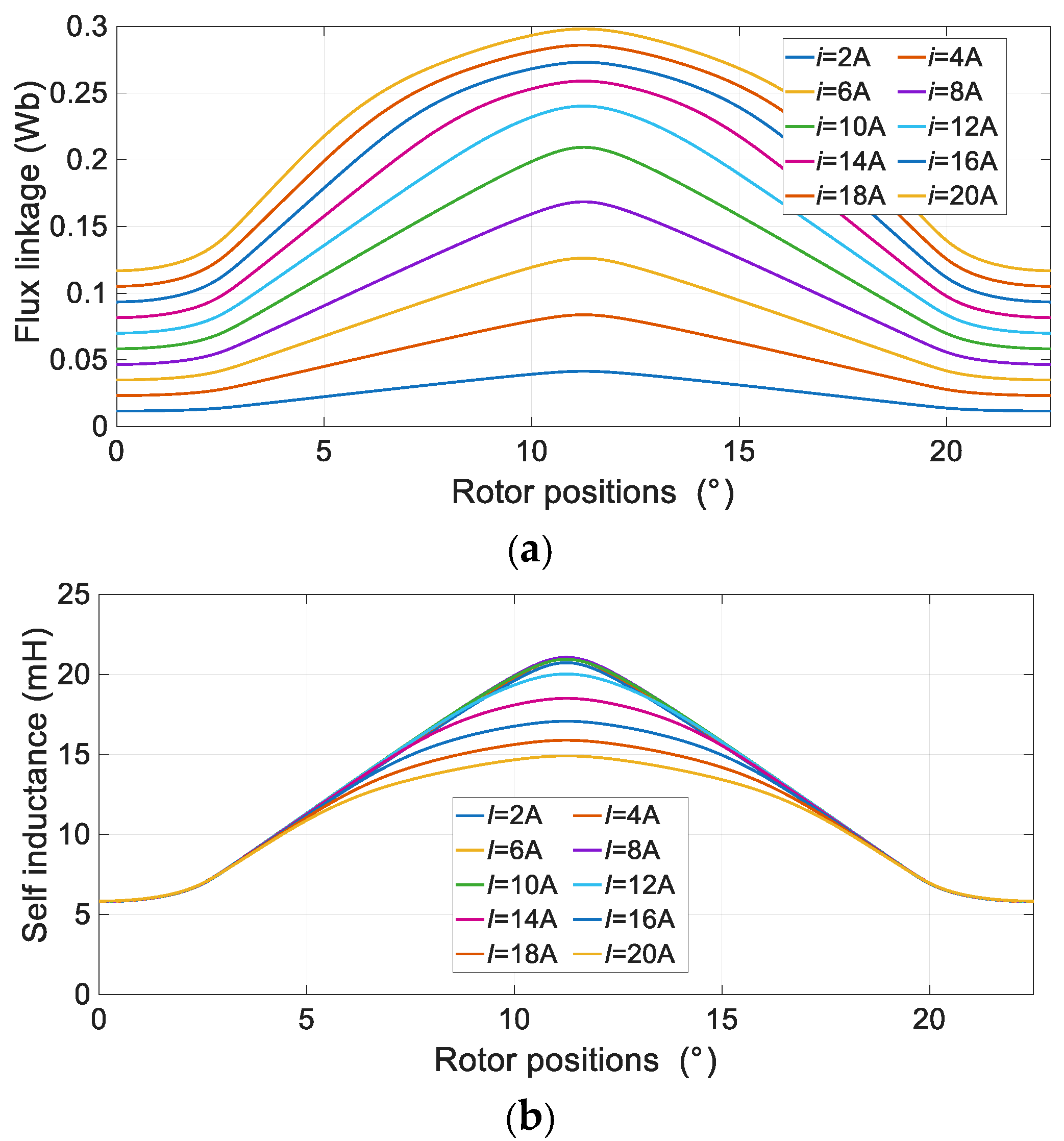
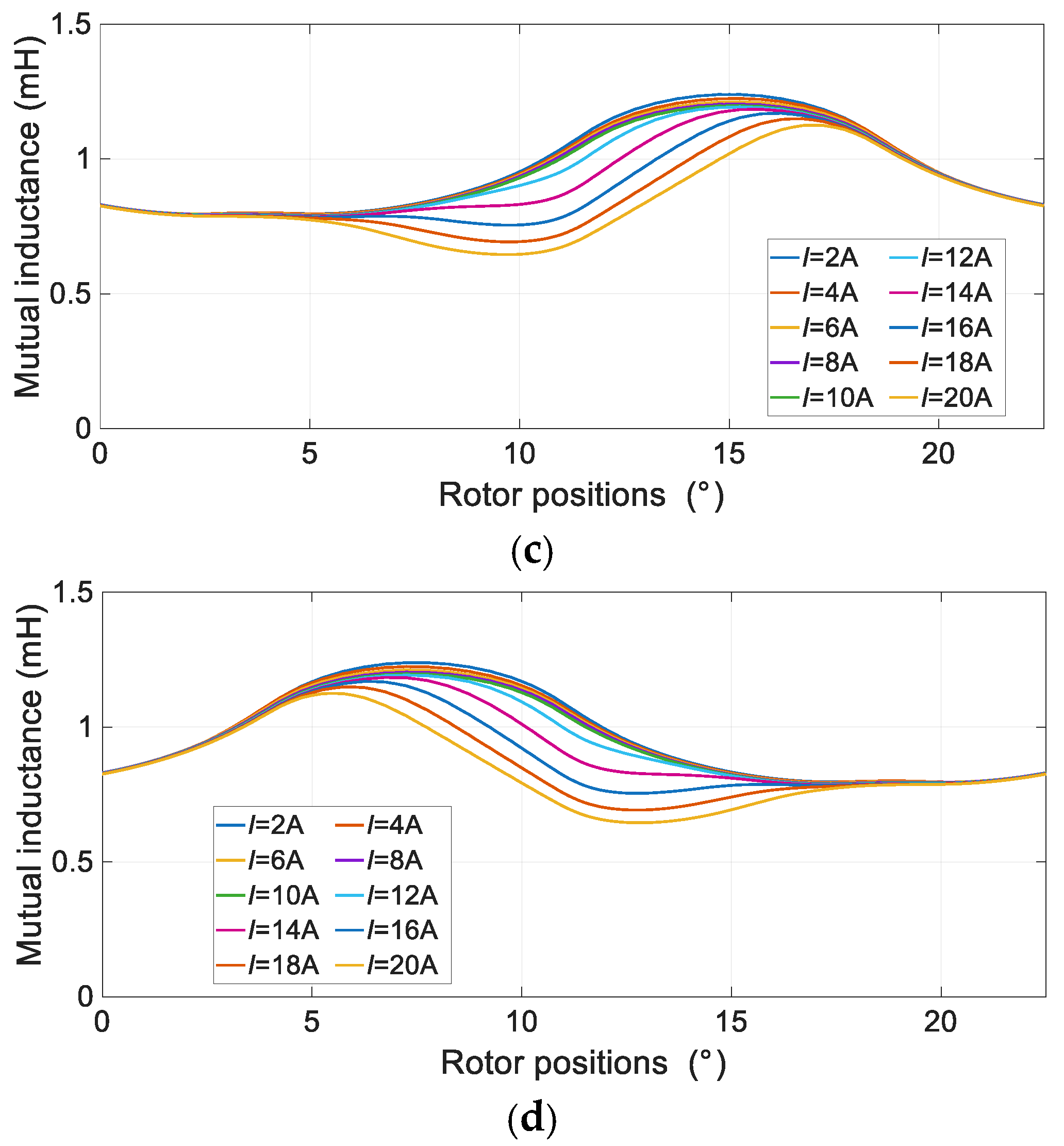
Under laboratory conditions, it is easier to measure self-inductance. Measurement of flux linkage is more difficult to implement in practice. Phase self-inductance, especially in the unaligned position, is a characteristic parameter of the SRM. (Figure 5a,b) show the dependence of the main flux linkage (Figure 5a) and self-inductance (Figure 5b) on the rotor position for Variant V3 at I = var. Very similar results were obtained for Variants V1 and V2. Therefore, these results are not presented in this paper.
Figure 5.
Flux linkage and inductance vs. rotor positions at I = var of variant V3: (a) flux linkage Ph1, (b) self Ph1, (c) mutual Ph1 and Ph2, (d) mutual Ph1 and Ph3.
The mutual inductances between phases constitute a significant percentage of the self-inductance value of a given phase (max. ~8%). The variation between the maximum and minimum values of mutual inductance is small. Although its waveform depends on the rotor angle, it changes in the opposite direction to self-inductance. Therefore, its effect can be considered marginal. The value of the supply current in the winding has an even smaller impact on the mutual inductances of the motor. In this case, the influence of the main winding current can be considered negligible. This allows certain simplifications in the mathematical model.
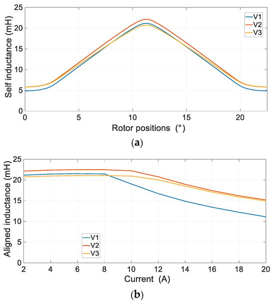
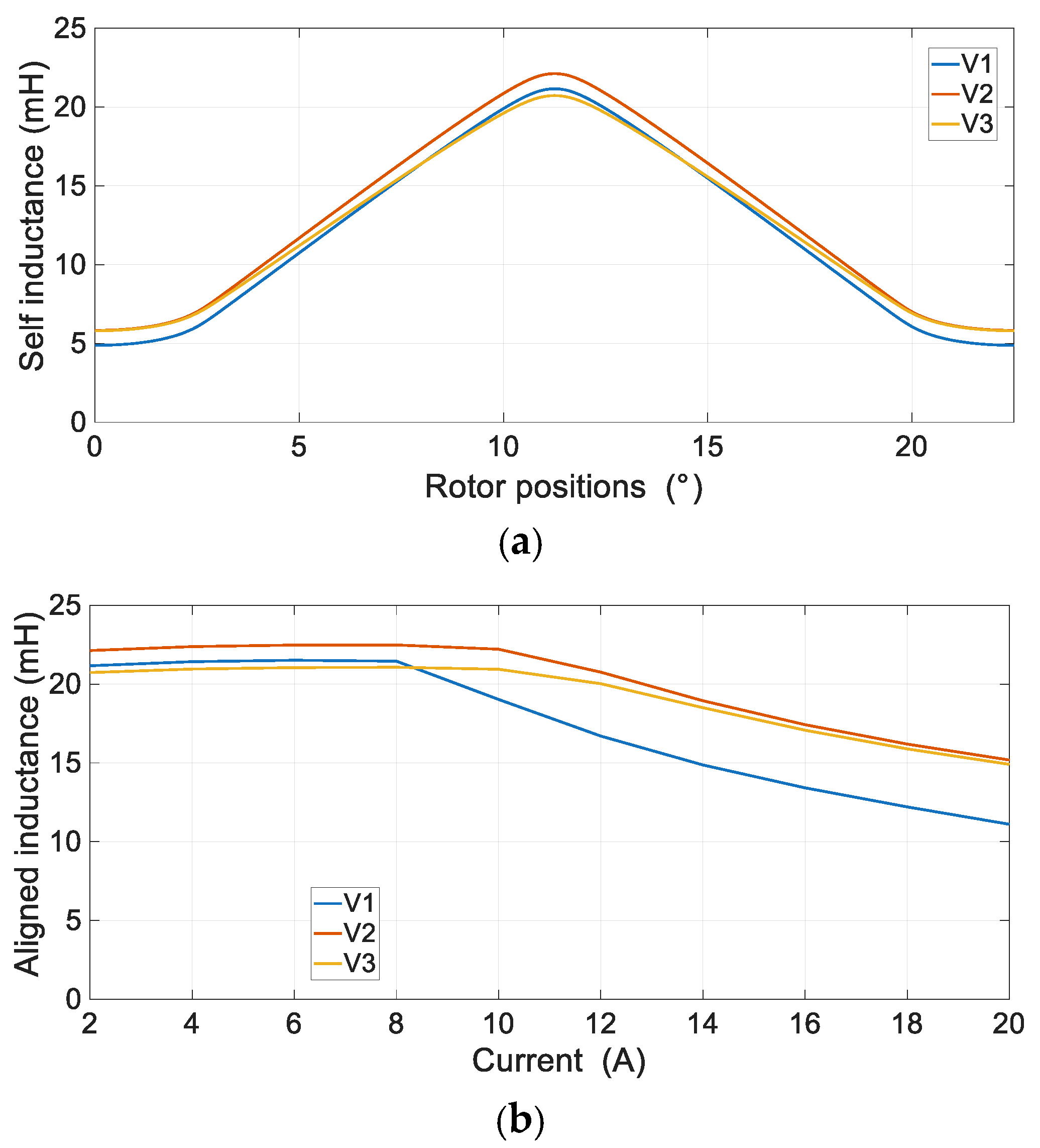
Figure 6a shows the self-inductance characteristics of the three design variants determined at a supply current of I = 2 A.
Figure 6.
(a) Self-inductance vs. rotor positions at I = 2 A; (b) aligned inductance vs. currents.
The V1 variant has the lowest value of inductance Lu in the unaligned position. Simultaneously, the V1 variant also has the lowest value of La inductance at the aligned position. The V3 variant has the highest inductance value in the unaligned position; however, the V2 variant is characterized by a practically comparable inductance value in the same position. The differences between the V1, V2 and V3 variants result from the different arrangement of the winding within the slot space. The La/Lu ratio for the V1, V2, and V3 variants achieves values of 4.3, 3.8, and 3.6, respectively. The unaligned inductance affects the motor base speed (constant-torque operating state) as well as the constant-power operating range and maximum speed. With identical winding data for the analyzed constructions, the V2 and V3 variants will have base-speed values that are several percent lower than that of the V1 variant. The most significant differences among the V1, V2, and V3 variants can be observed in the aligned-inductance characteristics (Figure 6b). The V1 variant demonstrates the least favorable performance in this regard owing to its higher susceptibility to magnetic-circuit saturation. By comparison, the V2 and V3 variants, featuring modified winding configurations, exhibit nearly identical behavior.
4.3. Electromagnetic Torque Characteristics
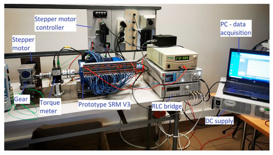
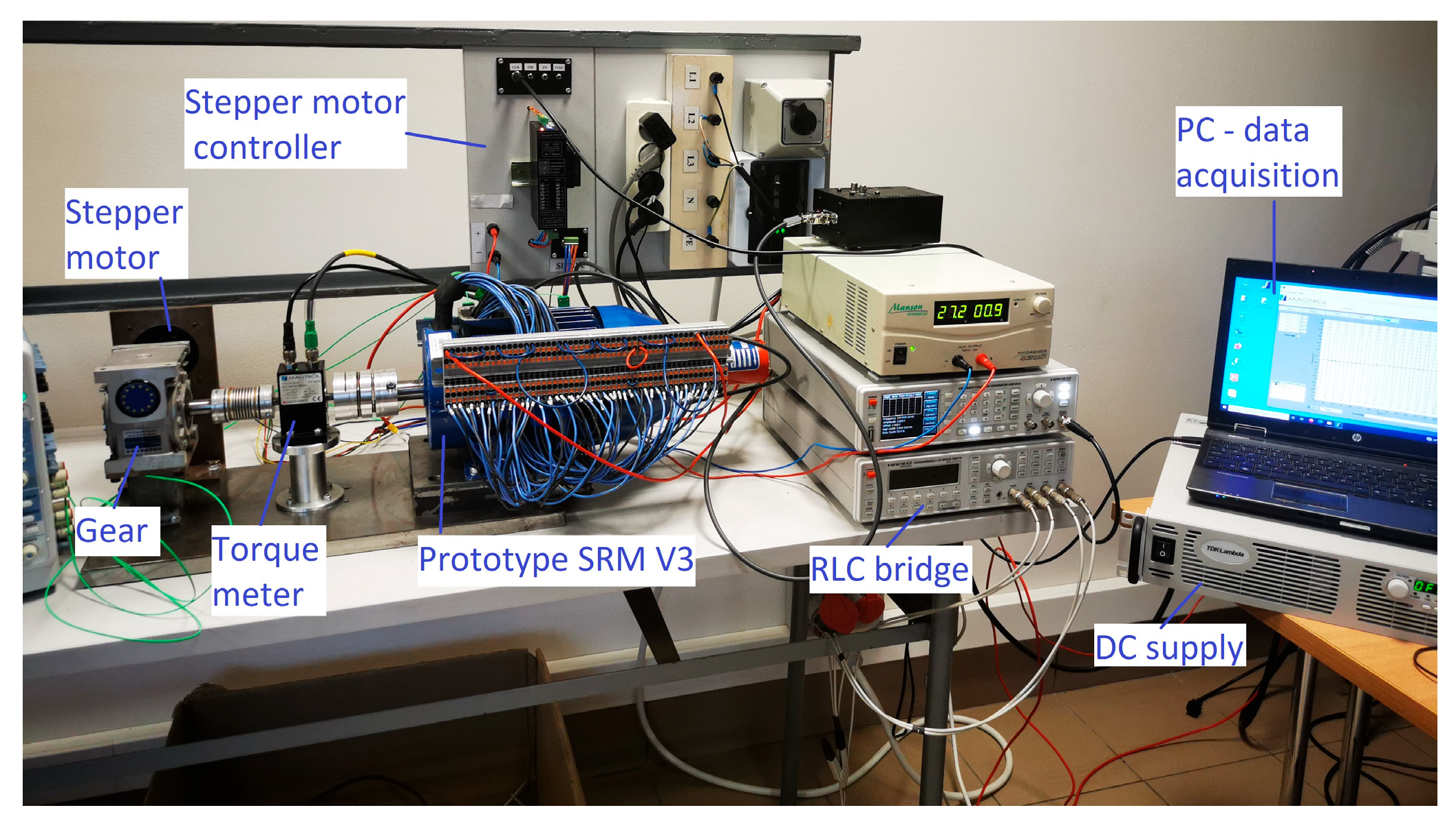
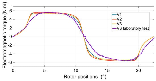
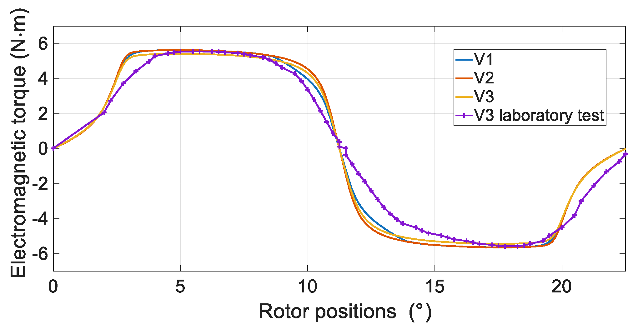
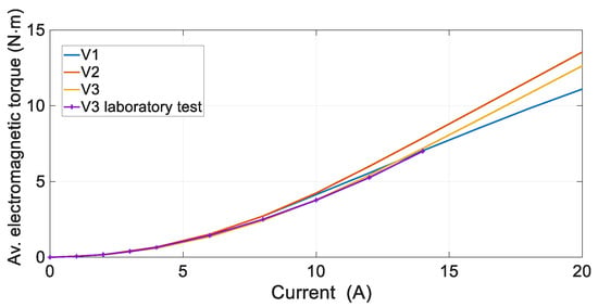
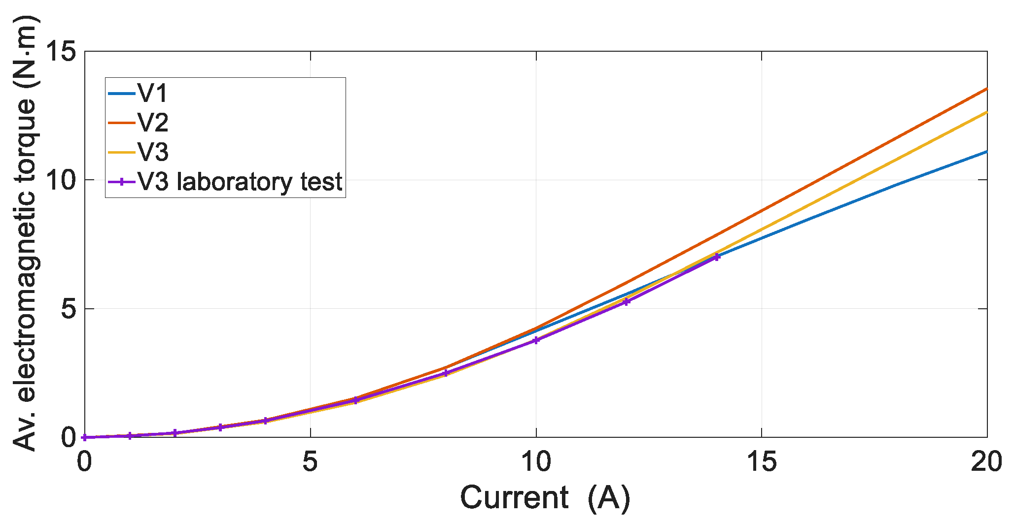
On the basis of the numerical models, the static electromagnetic torque characteristics as a function of rotor position and current were determined. The measurement setup for the laboratory tests under static conditions is shown in Figure 7. The numerical calculations were carried out using Phase 1 as an example. The dependence of the electromagnetic torque on the position of the rotor is shown in Figure 8 for I = 10 A for the V1, V2 and V3 variants. The V3 variant was subjected to laboratory tests. An example of the test results is shown in Figure 8. Figure 9 shows a comparison of the average electromagnetic torque as a function of current for the V1, V2, and V3 variants.
Figure 7.
Stand test I—static characteristics.
Figure 8.
Electromagnetic torque vs. rotor position at I = 10 A.
Figure 9.
Average electromagnetic torque vs. current.
The average electromagnetic torque value shown in Figure 9 corresponds to the half-period average. For the static electromagnetic torque characteristics presented in Figure 8, the average value was calculated over the rotor-position range from 0° to 11.25° mechanical (180° electrical). The V2 variant provides the highest electromagnetic torque among all considered configurations. At higher current levels, the lowest torque values are observed for the V1 variant, which employs the conventional winding arrangement. For high stator-to-rotor pole overlap, the reduction in electromagnetic torque is most pronounced, as illustrated in Figure 8. Experimental results indicate that the V3 prototype produces a slightly lower electromagnetic torque than that predicted by the numerical analysis. This discrepancy can be attributed to manufacturing tolerances as well as to the degradation of the magnetic properties of the stator and rotor magnetic circuits.
The proposed V2 and V3 solutions generate practically the same electromagnetic torque values for the same current excitation. Satisfactory agreement between the numerical and experimental results was obtained for the V3 variant (Figure 8 and Figure 9). Under real operating conditions, a slightly lower electromagnetic torque was obtained. This effect is particularly noticeable when approaching the aligned position of the supplied phase (Figure 8).
5. Analysis of Waveforms, Losses and Efficiency for SRM Winding Variants
5.1. Constant Torque Operation
Time domain waveforms were obtained using transient finite element simulations coupled with a field–circuit model. In the circuit domain, the power converter shown in Figure 3b was modeled. For the transient analysis under constant-torque operating conditions, a fixed time step of 5 μs was applied throughout the simulation.
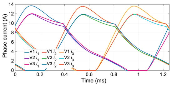
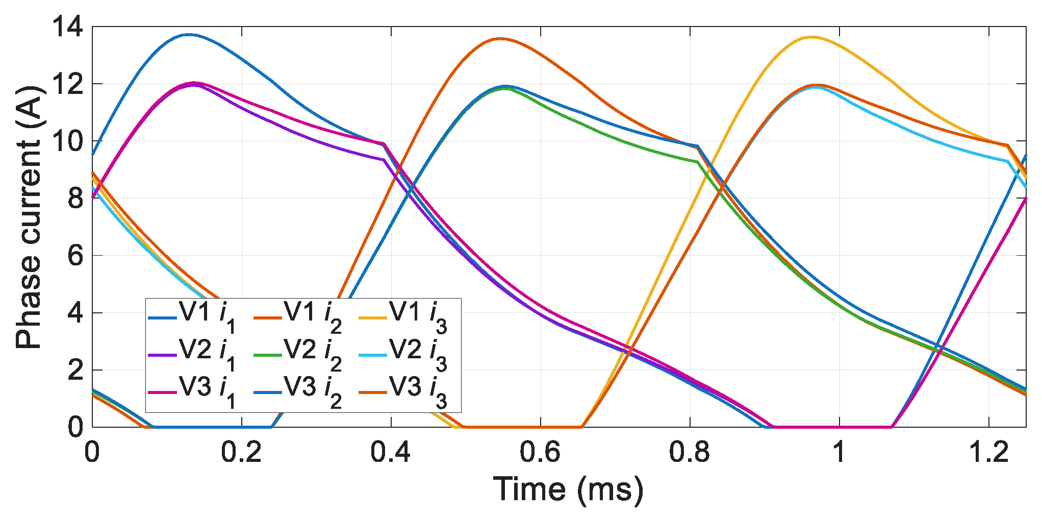
In the constant-torque operating range, current control is used. The torque value on the motor shaft mainly determines the reference current value of the current regulator, Iref. In the case of an SRM, additional control parameters must also be specified, namely, the control angles, i.e., the turn-on angle (θon = −1.25° mech.) and the turn-off angle. Alternatively, the conduction angle is sometimes used instead of the turn-off angle (Δθ = 9.75° mech.). Assuming the use of a complete mathematical model of the motor (including all magnetic couplings), the waveforms of current, electromagnetic torque, and power losses (in the winding and in the iron) were obtained. Identical control parameters and the same operating point were used for each variant (n = 1500 rpm, Iref = 14 A).
The following relationship was used to determine the efficiency:
where: Pout—the output power; ΔPmech—the mechanical losses. The mechanical loss characteristic was determined under laboratory conditions. The SRM machine prototype, in an unexcited state, was driven by an induction motor supplied from a frequency inverter. The shaft power of the induction motor corresponds to the mechanical losses of the tested SRM prototype.
The winding losses are:
and the iron losses
where: lFe—motor active length; ρ—resistivity of copper; J—current density; S—area of copper; kh, kc, ke—ratio; f—frequency of current; and Bm—flux density. The coefficients kh, kc and ke depend on the type of electrical steel used. Their values are as follows: kh = 222.96 , kc = 0.17 , and ke = 3.09 .
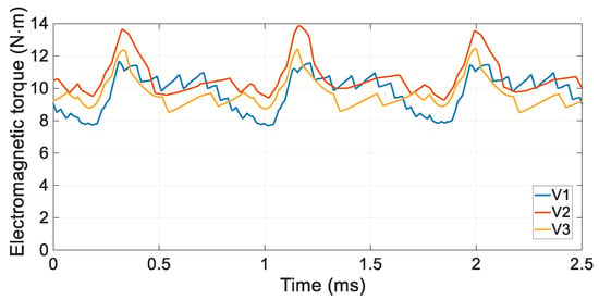
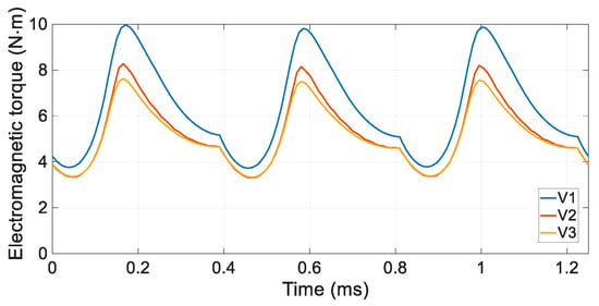
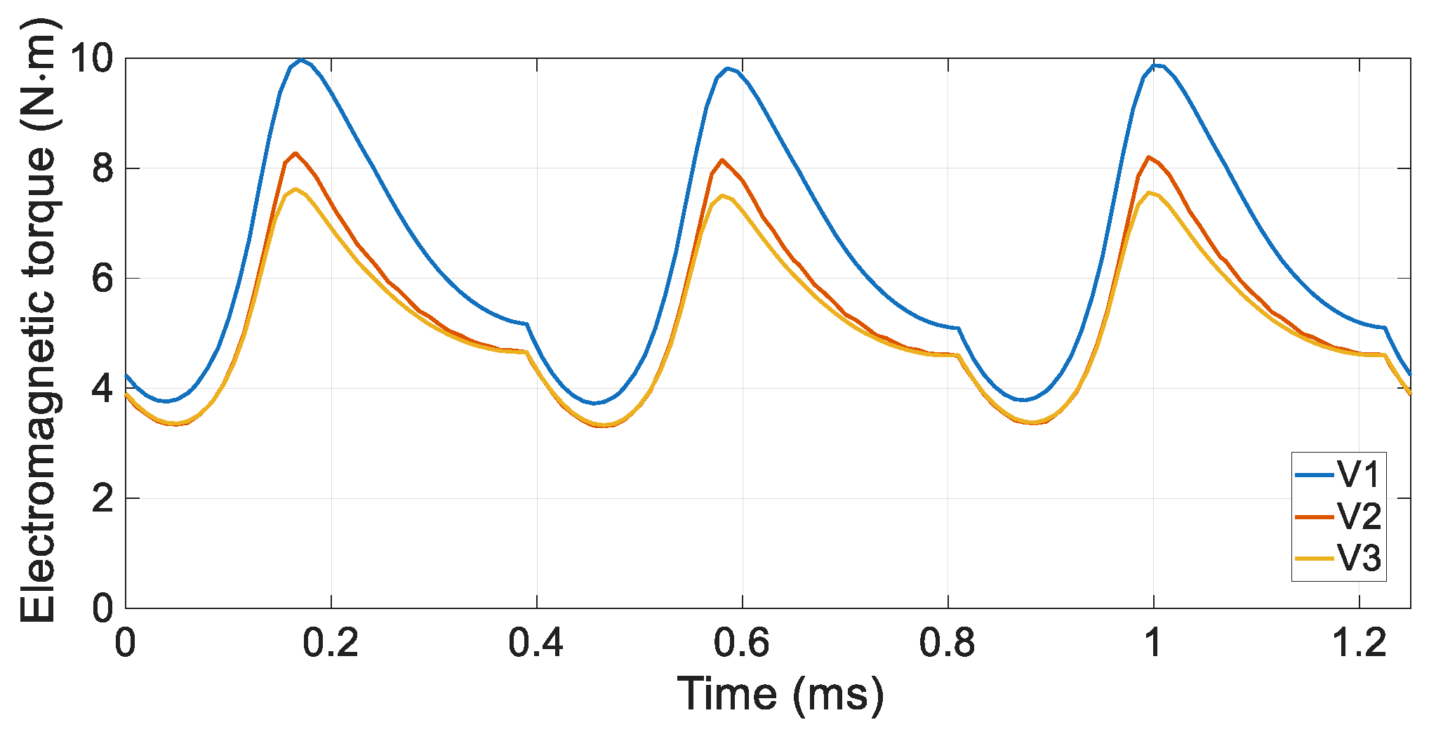
The waveforms obtained for current and electromagnetic torque are shown in Figure 10 and Figure 11. The power losses are shown in Figure 12.
Figure 10.
Current waveforms for V1, V2, and V3 variants.
Figure 11.
Electromagnetic torque for V1, V2, and V3 variants.
Figure 12.
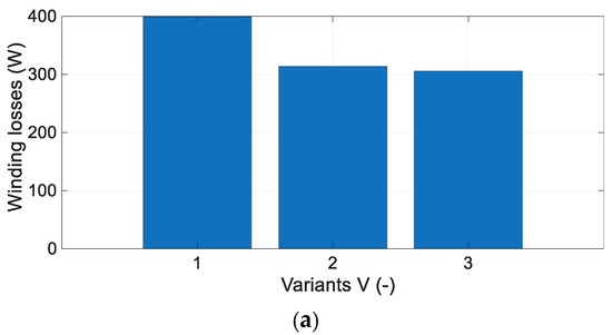
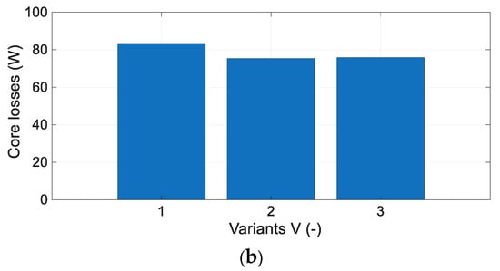
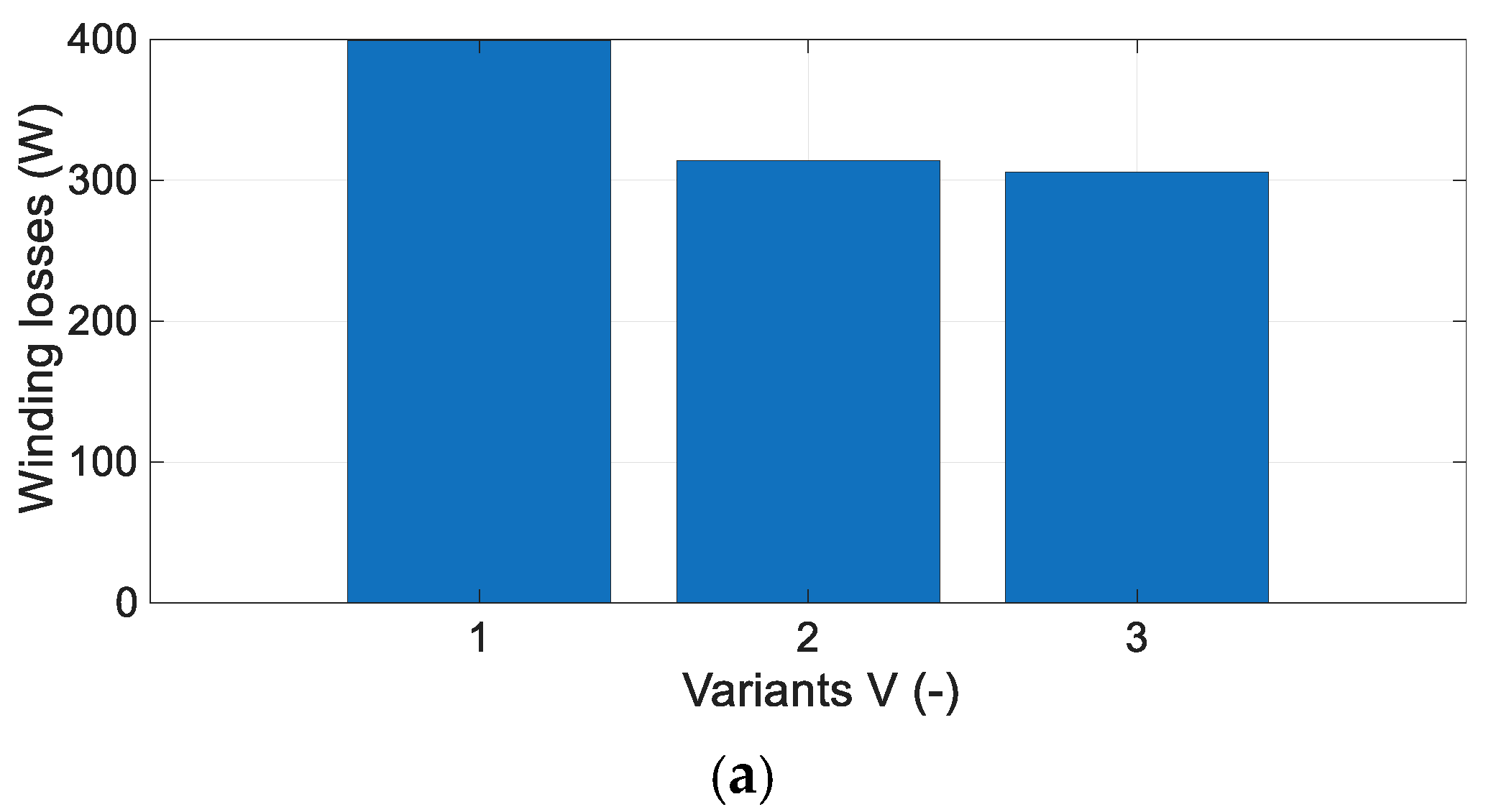
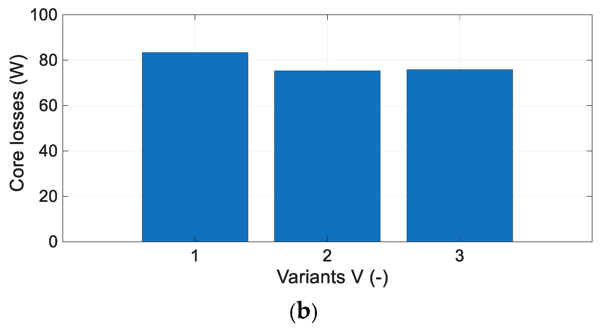
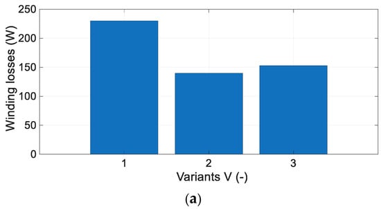
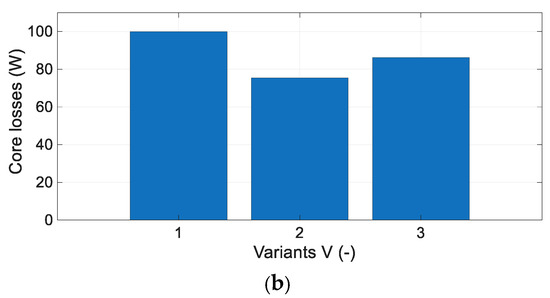
Power losses for variants V1, V2, and V3 in constant torque operation: (a) winding losses; (b) core losses.
In the constant-torque range, the current regulator sets the reference current value. Therefore, the differences between the individual variants are relatively small. In the case of the V1 variant, due to the lower inductance value in the unaligned position, the current increases slightly faster than in the remaining variants. For similar levels of RMS phase current, the V2 variant achieves the highest average electromagnetic torque of 10.6 N·m. On the contrary, the V1 and V3 variants exhibit comparable average torque values, both reaching approximately 9.7 N·m. Significant differences appear in the losses of motor windings. The classic V1 variant has winding losses that are much higher (399 W) than those of the proposed V2 (314 W) and V3 (306 W) variants, assuming a constant winding resistance value. The iron losses of the V1 variant are slightly higher, reaching 84 W, while the corresponding losses for the V2 and V3 variants are 75 W. The V1 and V3 variants exhibit nearly identical shaft power, approximately 1500 W. On the contrary, the V2 variant provides the highest shaft power output of 1610 W. The resulting motor efficiencies for all variants investigated are presented in Table 5.
Table 5.
Motor efficiency in the range of constant torque.
The efficiency of the V2 and V3 variants is higher than that of the V1 variant, increasing by 4% for V2 and 3.4% for V3, respectively. This significant improvement in efficiency confirms the effectiveness of the proprietary solutions. The results presented in Table 5 were obtained without considering thermal effects and assuming a constant winding resistance. This approach enables a direct assessment of the impact of the proposed solutions under identical operating conditions. In a practical system, the winding temperature increases depending on the applied cooling method. Consequently, winding losses increase, resulting in a reduction in efficiency. Therefore, the performance differences between Variant V1 and Variants V2 and V3 are expected to become even more pronounced. The estimated temperature increase for V1 is approximately 30 °C higher than for V2 and V3.
5.2. Constant Power Operation
When the rotational speed is increased, both the control parameters and the transient analysis time step must be adjusted. In this study, the transient analysis time step was reduced to 1 μs. The turn-on angle must be increased to achieve the required peak phase current. For the operating point considered, the turn-on angle was set at −3.25° mechanical, while the conduction angle was 10.25° mechanical. At the operating point under analysis, the switching frequency is 800 Hz. Given a winding wire diameter of0.63 mm, the effects of skin effect can be neglected. The current penetration depth is approximately 2.3 mm, given a copper resistivity of 1.72 × 10⁻⁸ Ωm at a temperature of 20 °C. This allows this effect to be neglected in the calculations. Additionally, proximity effects were neglected in the calculations.
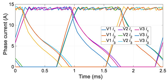
In the case of an SRM, constant-power operation is achieved by changing the control angles (mainly the turn-on angle). An operating point above the base speed of the analyzed motor was selected for analysis (n = 3000 rpm). As in the case of current control, calculations were performed using the full model and assuming the same control parameters. The waveforms of current and electromagnetic torque are shown in Figure 13 and Figure 14. The power losses are shown in Figure 15.
Figure 13.
Waveforms of current for V1, V2 and V3 variants.
Figure 14.
Waveforms of electromagnetic torque for V1, V2 and V3 variants.
Figure 15.
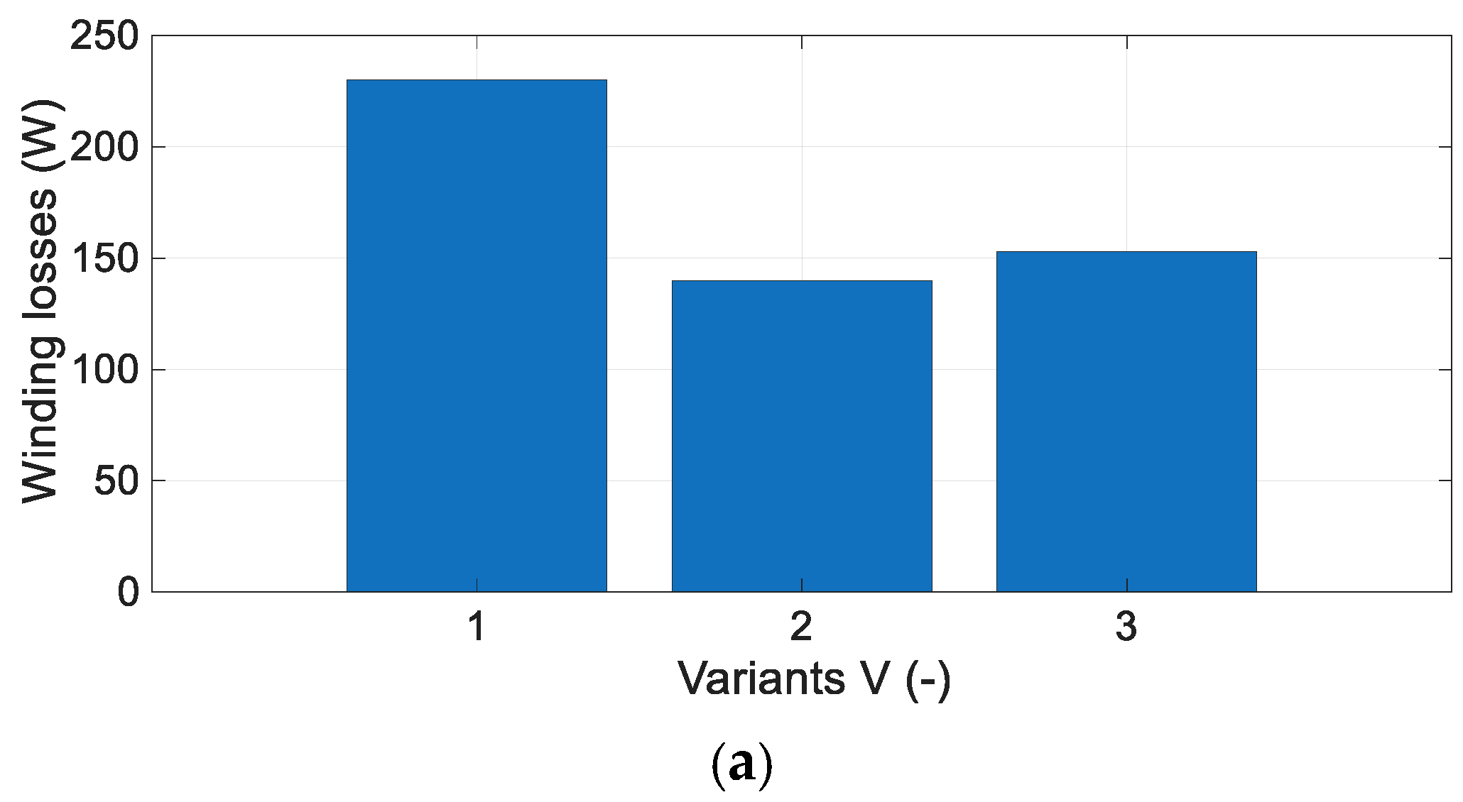
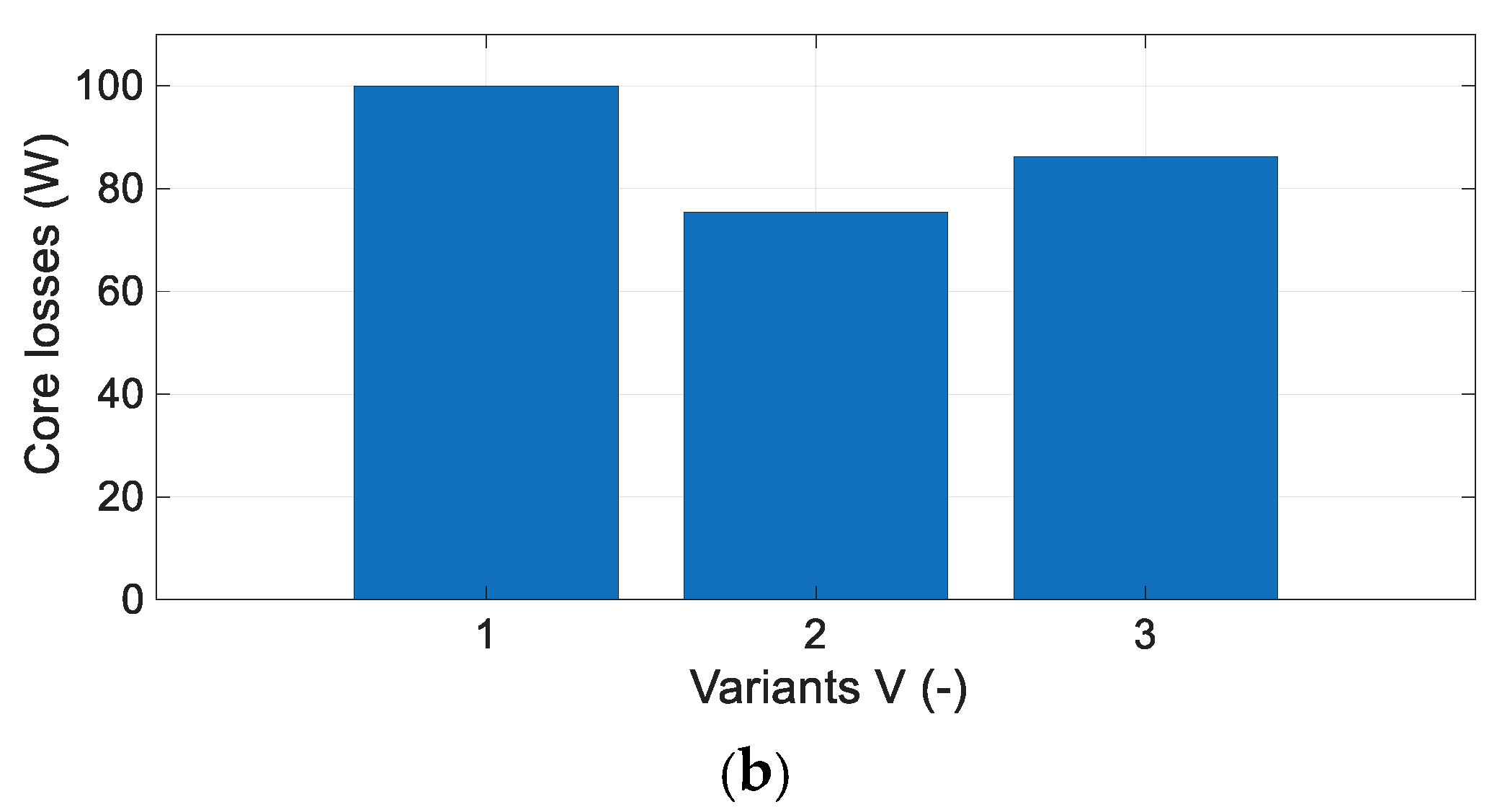
Power losses for variants V1, V2, and V3 in constant-power operation: (a) winding losses; (b) core losses.
The differences in the current waveforms between the conventional variant and the remaining designs become more pronounced. Consequently, the generated electromagnetic torque is also affected. The V1 variant produces a higher electromagnetic torque at a given rotational speed under identical control conditions. This behavior is expected, as the V1 variant exhibits a slightly wider constant-power operating range. At the same time, the V1 variant is characterized by higher copper losses (230 W) than the V2 (140 W) and V3 (160 W) variants. The V1 variant also exhibits the highest iron losses, reaching 100 W. On the contrary, the V2 variant achieves the lowest iron losses of 75 W, while the V3 variant shows intermediate losses of 86 W. Similarly to the operation in the constant-torque region, the V2 and V3 variants achieve a higher energy conversion efficiency, as summarized in Table 6.
Table 6.
Motor efficiency in the range of constant power.
Under constant-power operation, the V2 and V3 variants achieved efficiency increases of approximately 2% (2.4% for V2 and 2% for V3), respectively. This improvement is slightly smaller than that obtained under constant-torque operation. It indicates that, at the operating point, the V1 variant produced a slightly higher electromagnetic torque. This is influenced by the lower inductance value in the unaligned position (Figure 6a). Under constant-power operation, accounting for thermal effects is also expected to result in a reduction in efficiency. This will further increase the efficiency gap between Variant V1 and Variants V2 and V3.
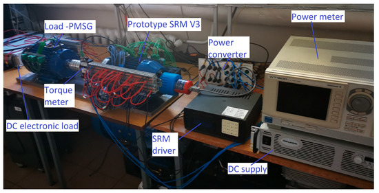
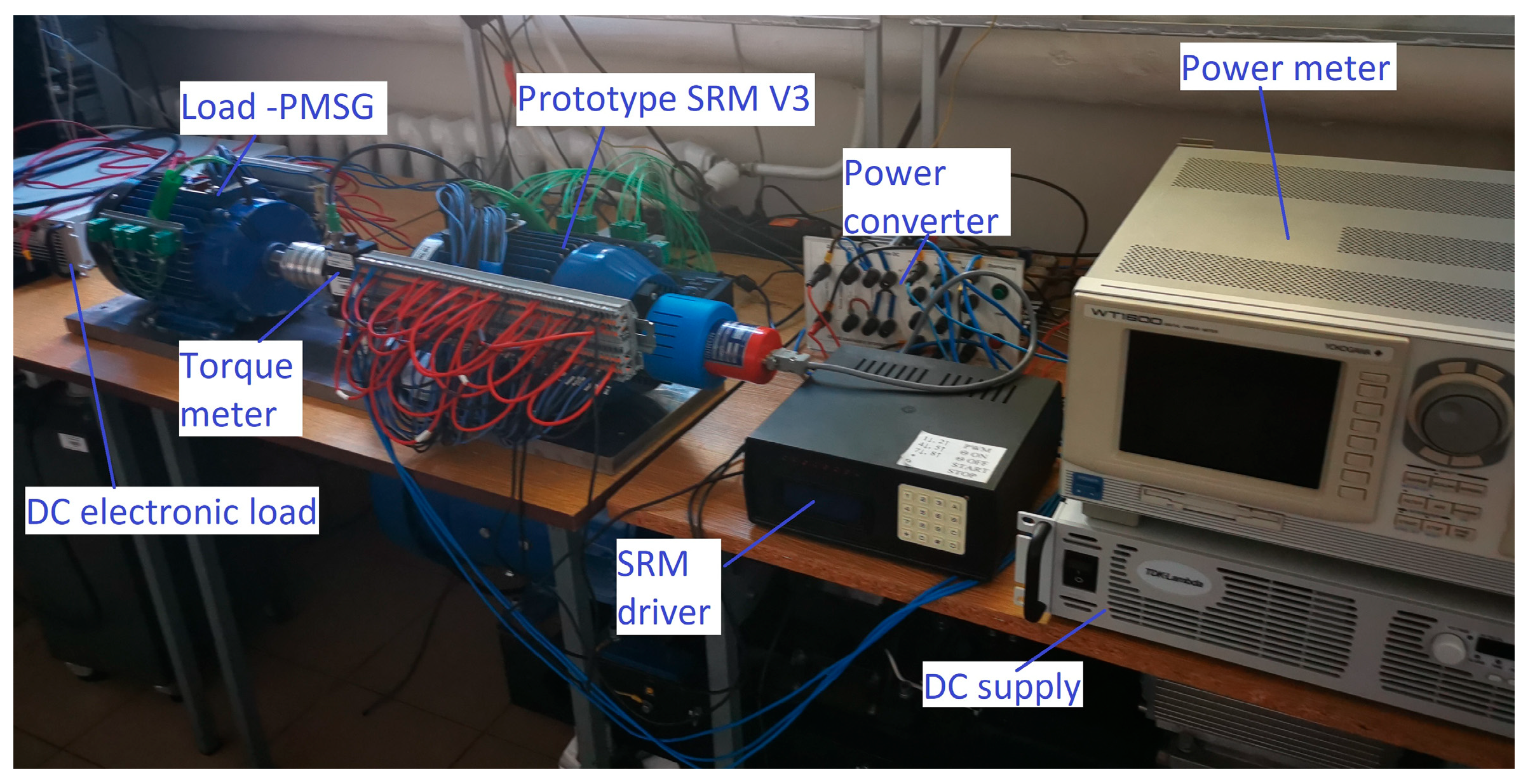
The manufactured V3 prototype was experimentally tested on the test bench shown in Figure 16. Time-domain waveforms were recorded using a Yokogawa DL850 scopeCorder data acquisition system (Tokio, Japan). Load torque and rotational speed were measured using a Magtrol TS107 dynamometer (10 Nm, 15,000 rpm) (Rossens, Switzerland). Electrical parameters, load torque, and rotational speed were acquired using a Yokogawa WT1600 power analyzer (Tokio, Japan). The power converter was supplied by a TDK-Lambda DC power supply rated at 300 VDC and 3.3 kW (Tokio, Japan). Current probes with a sensitivity of 100 mV/A were used to measure the branch currents.
Figure 16.
Stand test II—waveforms of currents.
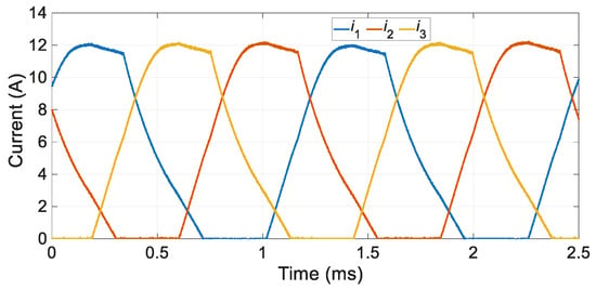
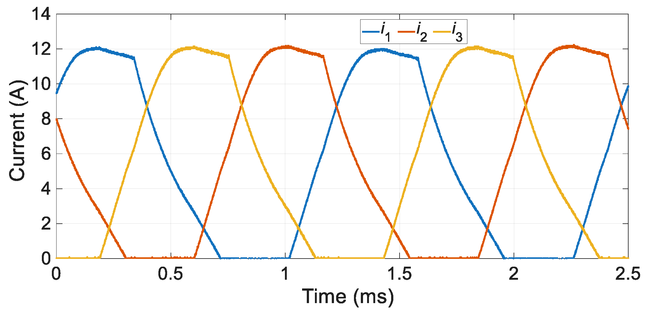
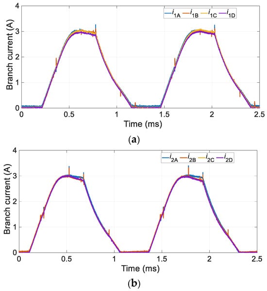
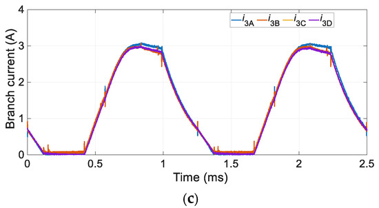
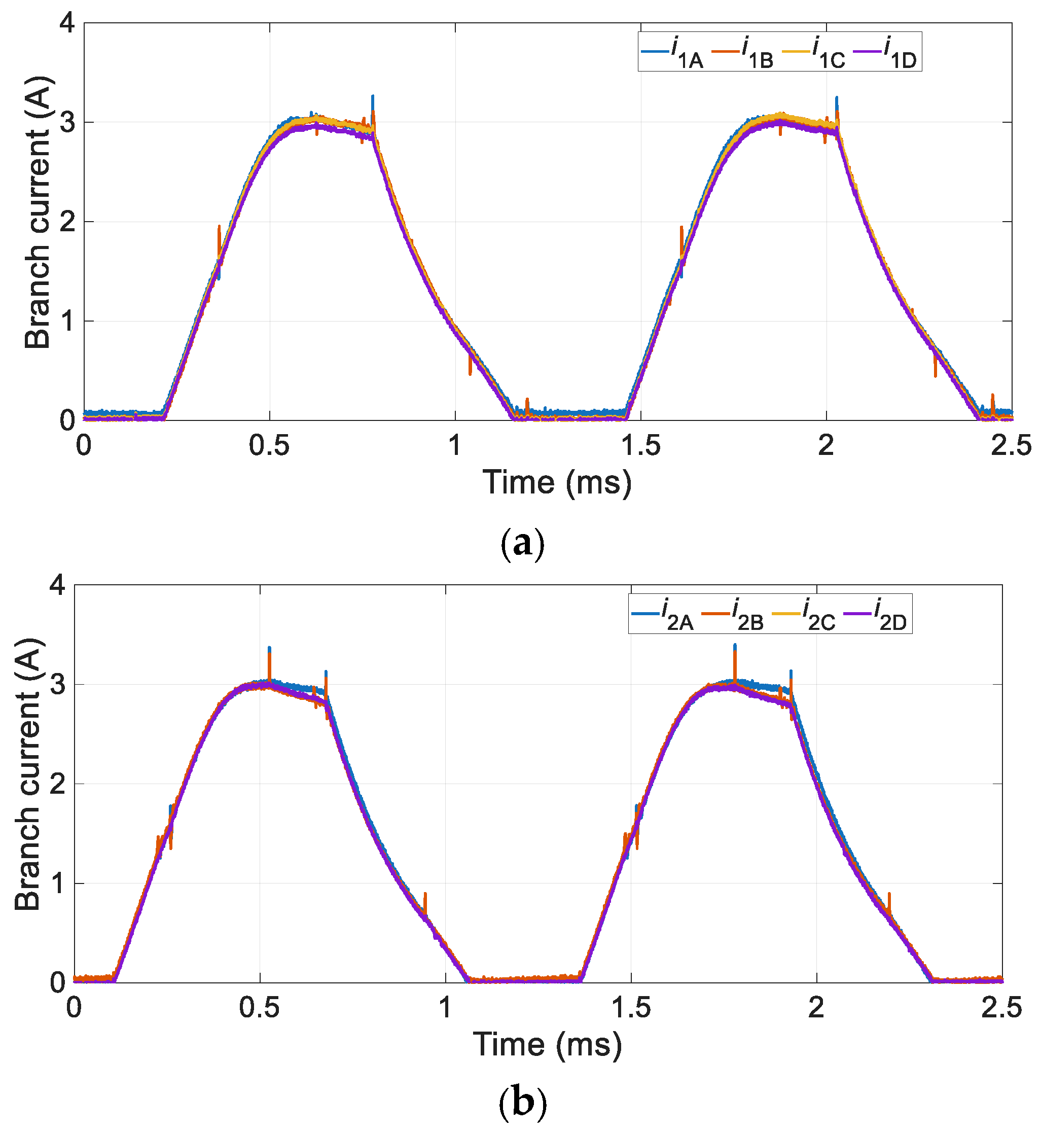
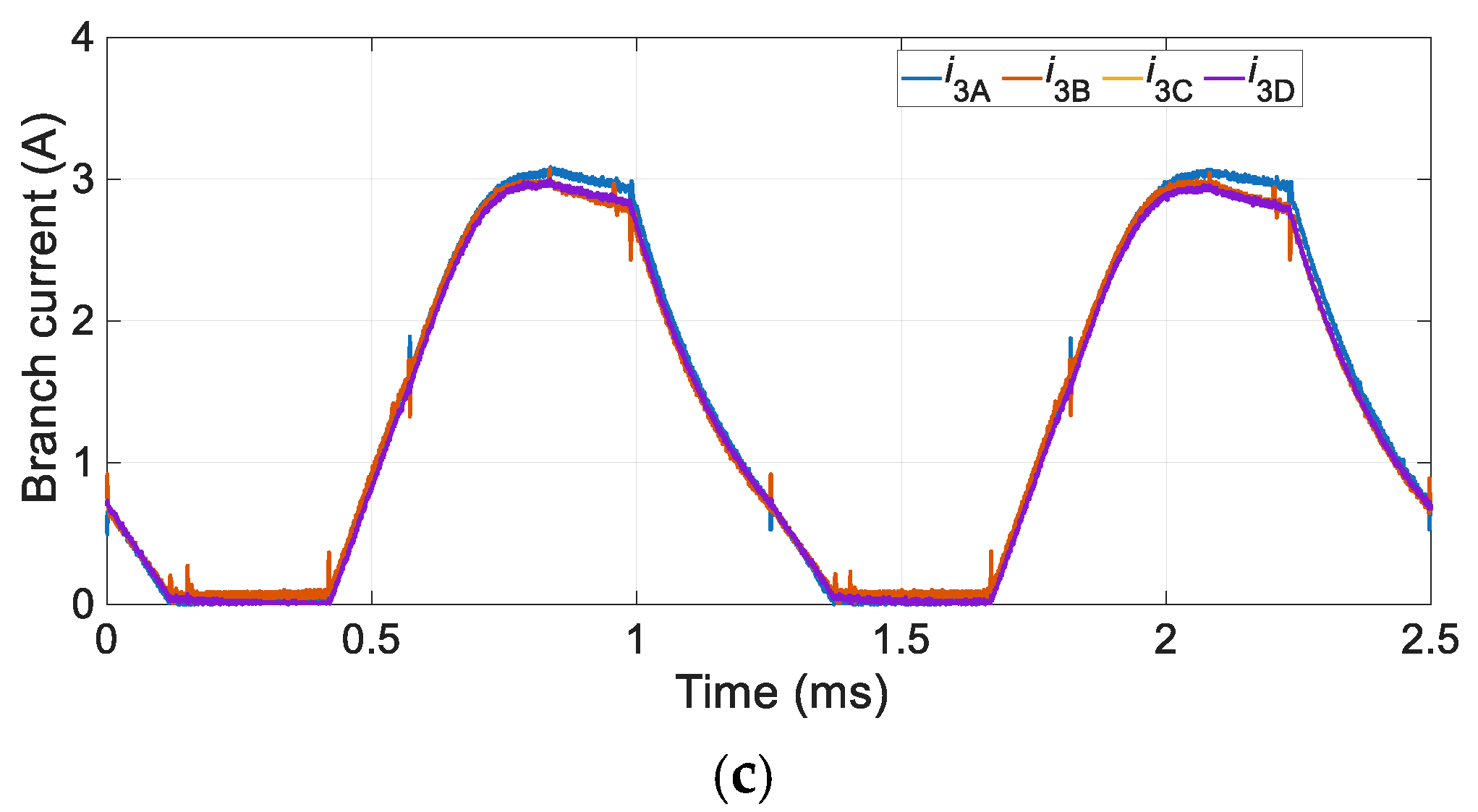
For the prototype V3 operating under identical conditions, including the same supply voltage, control settings, and rotational speed, representative phase current waveforms were measured and are presented in Figure 17. Furthermore, the branch currents of each phase were recorded and are shown in Figure 18a for Ph1, Figure 18b for Ph2 and Figure 18c for Ph3.
Figure 17.
Waveforms of phase currents.
Figure 18.
Waveforms of branch currents: (a) Ph1, (b) Ph2, (c) Ph3.
The phase current waveforms, obtained as the sum of the corresponding branch currents, closely match those predicted by the numerical analysis shown in Figure 13. Furthermore, a high degree of phase–current symmetry was observed. More pronounced deviations can be observed in the branch current waveforms presented in Figure 18. Since the parallel branches are mechanically shifted by 90° with respect to one another, the winding configuration is inherently more sensitive to manufacturing tolerances. Consequently, minor differences are expected between the branch currents of the individual phases. However, no evidence of circulating currents was detected, indicating that the branch currents within each phase remain mutually independent.
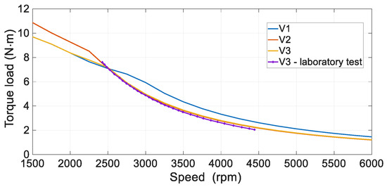
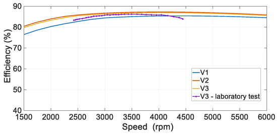
Representative torque–speed characteristics were determined for all variants considered. In addition, the mechanical characteristic of the V3 prototype was experimentally measured using the test setup shown in Figure 16 to allow a direct comparison with the numerical results. Both the simulations and the laboratory measurements were performed using the same supply and control parameters as those adopted for the current waveform analysis. The resulting torque–speed and efficiency characteristics are presented in Figure 19 and Figure 20, respectively.
Figure 19.
Torque load vs. speed.
Figure 20.
Efficiency vs. speed.
Although the V1, V2 and V3 variants share the same geometry, winding parameters, and control settings, their mechanical characteristics differ considerably. As illustrated in Figure 19, the variants exhibit different base speeds, with V2 having the highest base speed (10%) and V3 the lowest (8%). However, all variants exhibit a very similar CP/CT ratio of approximately 2.9. Although the V1 variant delivers the highest electromagnetic torque in the field-weakening region, its efficiency remains noticeably lower over the entire speed range (Figure 20). The highest efficiency is achieved by the V2 variant, whereas the efficiency of the V3 variant is only slightly lower and remains comparable throughout the operating range. Experimental investigations of the manufactured V3 prototype confirm the validity of the numerical model. However, both the measured load torque and the resulting efficiency are slightly lower than those predicted by the simulations. According to the authors, the V2 and V3 configurations offer the potential to achieve higher efficiency, albeit at the expense of a reduction in the developed electromagnetic torque when operating in the constant-power region. If higher torque is required in this operating range, despite a lower efficiency, the V1 configuration should be selected.
6. Conclusions
As demonstrated by the results, for the same winding data, the proposed V2 and V3 topologies achieve significantly lower winding losses and higher motor efficiency. The results obtained confirm that the winding arrangement has a substantial influence on the SRM performance. Although the V3 variant achieves the lowest phase resistance, the V2 variant provides the most favorable overall performance characteristics. The increased copper fill factor directly contributes to the reduction in copper losses. Furthermore, the V2 winding configuration enables higher electromagnetic torque production, particularly in the constant-torque operating region, where elevated phase currents occur. In comparison, the conventional V1 design exhibits the lowest electromagnetic torque under high-excitation conditions. Experimental validation was carried out on the V3 prototype only; the performance of V2 is evaluated by simulation, and its experimental verification is left for future work. It should also be noted that the maximum utilization of the slot space in the V2 design makes it impossible to replace a single pole winding. This is a drawback of this design. The V3 configuration does not have this drawback, as it allows for local replacement of pole windings. Improving motor efficiency comes at the cost of reduced resistance to potential failures due to the reduced distance between the windings of adjacent phases.
The results further indicate that the application of four parallel winding branches does not lead to circulating currents, which are commonly encountered in conventional DC and AC machines.
Future research will focus on a comparative analysis of the V1, V2 and V3 variants under alternative supply configurations for multiphase structures, as well as their behavior under asymmetric operating conditions, such as open-phase faults and partial short-circuit faults in either the power supply system or the machine itself.
The investigated winding configurations are suitable for operation with non-conventional power supply architectures, including dual-channel and four-channel converter systems. In such applications, mutual magnetic coupling is expected to play an important role, since the individual supply channels become effectively coupled through the mutual inductances. The impact of this phenomenon on multichannel operation will constitute the subject of future investigations.
Author Contributions
Conceptualization, M.K.; methodology, M.K. and J.P.; software, M.K.; validation, M.K.; formal analysis, J.P. and A.K.; investigation, M.K.; resources, M.K., J.P., K.K.-K. and A.K.; data curation, M.K.; writing—original draft preparation, M.K.; writing—review and editing, J.P., K.K.-K. and A.K.; visualization, M.K.; supervision, J.P.; project administration, M.K.; funding acquisition, M.K. All authors have read and agreed to the published version of the manuscript.
Funding
This research received no external funding.
Data Availability Statement
The original contributions presented in this study are included in the article. Further inquiries can be directed to the corresponding author.
Acknowledgments
We gratefully acknowledge D.A. Torrey for his valuable comments and constructive feedback on this manuscript. The authors also thank Grzegorz Podskarbi for performing selected static tests of the investigated prototype.
Conflicts of Interest
The authors declare that they have no conflicts of interest.
Abbreviations
The following abbreviations are used in this manuscript:
| CA | Copper area |
| CSF | Copper slot fill |
| CW | Concentric winding |
| DLTS/SW | Double-layer trapezoidal side/side winding |
| DLVS/SW | Double-layer V-shape side/side winding |
| DLU/LW | Double-layer upper/lower winding |
| SA | Slot area |
| SLDW | Single-layer distributed winding |
| SRM | Switched Reluctance Motor |
| TLDLW | Two-level double-layer winding |
| TW | Toroidal winding |
| WA1 | Winding area + wedge area + coil divider area |
| WA2 | Winding area |
References
- Dinolova, P.; Ruseva, V.; Dinolov, O. Energy Efficiency of Induction Motor Drives: State of the Art, Analysis and Recommendations. Energies 2023, 16, 7136. [Google Scholar] [CrossRef] [Scilit]
- Husain, I.; Ozpineci, B.; Islam, M.S.; Gurpinar, E.; Su, G.-J.; Yu, W.; Chowdhury, S.; Xue, L.; Rahman, D.; Sahu, R. Electric Drive Technology Trends, Challenges, and Opportunities for Future Electric Vehicles. Proc. IEEE 2021, 109, 1039–1059. [Google Scholar] [CrossRef] [Scilit]
- Stumpf, P.; Tóth-Katona, T. Recent Achievements in the Control of Interior Permanent-Magnet Synchronous Machine Drives: A Comprehensive Overview of the State of the Art. Energies 2023, 16, 5103. [Google Scholar] [CrossRef] [Scilit]
- Davarpanah, G.; Mohammadi, S. A New Switched Reluctance Motor with Embedded Permanent Magnets for Transportation Electrification. In Proceedings of the IECON 2024—50th Annual Conference of the IEEE Industrial Electronics Society, Chicago, IL, USA, 3–6 November 2024. [Google Scholar]
- Devito, G.; Nuzzo, S.; Barater, D. Rare-Earth Reduction in Electric Traction Motors: A Design-Oriented Review Linking Topology, Magnetic Materials, Soft-Magnetic Cores and Windings Across Ground-Vehicle Segments. Energie 2026, 19, 4316. [Google Scholar] [CrossRef] [Scilit]
- Du, G.; Zhang, G.; Li, H.; Hu, C. Comprehensive Comparative Study on Permanent-Magnet-Assisted Synchronous Reluctance Motors and Other Types of Motor. Appl. Sci. 2023, 13, 8557. [Google Scholar] [CrossRef] [Scilit]
- Abdulsamad, M.; Dhulipati, H.; Chaoui, H. Advances in the Analytical Modelling and Design of Synchronous Reluctance Machines for Electric Vehicles. Machines 2026, 14, 796. [Google Scholar] [CrossRef] [Scilit]
- Prakht, V.; Dmitrievskii, V.; Kazakbaev, V.; Valeev, E.; Goman, V. Traction Synchronous Motors with Rotor Field Winding: A Literature Review. World Electr. Veh. J. 2025, 16, 633. [Google Scholar] [CrossRef] [Scilit]
- Mahmouditabar, F.; Baker, N.J. Design Optimization of Induction Motors with Different Stator Slot Rotor Bar Combinations Considering Drive Cycle. Energies 2024, 17, 154. [Google Scholar] [CrossRef] [Scilit]
- Alam, S.U.; Li, S.; Hong, Y.-K.; Liu, Z.; Kamrul, M.I.; Choi, S.; Choi, M.; Yeo, C.-D.; Wahed, M.A. Comparative Evaluation of Performance Trade-Off Under Permanent Magnet Volume Reduction in SPM, IPM, and PM-Assisted SynRM. Appl. Sci. 2026, 16, 9923. [Google Scholar] [CrossRef] [Scilit]
- Guo, S.; Su, X.; Zhao, H. Optimal Design of an Interior Permanent Magnet Synchronous Motor for Electric Vehicle Applications Using a Machine Learning-Based Surrogate Model. Energies 2024, 17, 3864. [Google Scholar] [CrossRef] [Scilit]
- Zhao, J.; Guan, X.; Li, C.; Mou, Q.; Chen, Z. Comprehensive Evaluation of Inter-Turn Short Circuit Faults in PMSM Used for Electric Vehicles. IEEE Trans. Intell. Transp. Syst. 2021, 22, 611–621. [Google Scholar] [CrossRef] [Scilit]
- Chen, H.; Fang, C.; Dong, J.; Lu, S.; Pires, V.; Martins, J.; Aguirre, M.P. Diagnosis of Interturn Short-Circuit of SRM Based on Ratio of Current Components. IEEE Trans. Transp. Electrif. 2023, 9, 3319–3327. [Google Scholar] [CrossRef] [Scilit]
- Toda, H.; Senda, K.; Morimoto, S.; Hiratani, T. Influence of Various Non-Oriented Electrical Steels on Motor Efficiency and Iron Loss in Switched Reluctance Motor. IEEE Trans. Magn. 2013, 49, 3850–3853. [Google Scholar] [CrossRef] [Scilit]
- Chai, F.; Li, Z.; Chen, L.; Pei, Y. Effect of Cutting and Slot Opening on Amorphous Alloy Core for High-Speed Switched Reluctance Motor. IEEE Trans. Magn. 2021, 57, 8202705. [Google Scholar] [CrossRef] [Scilit]
- Korkosz, M.; Bogusz, P.; Prokop, J. Complex Performance Analysis and Comparative Study of Very High-Speed Switched Reluctance Motors. IEEE Trans. Magn. 2019, 55, 8204714. [Google Scholar] [CrossRef] [Scilit]
- Mao, S.-H.; Tsai, M.-C. A novel switched reluctance motor with C-core stators. IEEE Trans. Magn. 2005, 41, 4413–4420. [Google Scholar] [CrossRef]
- Lee, C.; Krishnan, R.; Lobo, N.S. Novel Two-Phase Switched Reluctance Machine Using Common-Pole E-Core Structure: Concept, Analysis, and Experimental Verification. IEEE Trans. Ind. Appl. 2009, 45, 703–711. [Google Scholar] [CrossRef] [Scilit]
- Vujičić, V.P. Minimization of Torque Ripple and Copper Losses in Switched Reluctance Drive. IEEE Trans. Power Electron. 2021, 27, 388–399. [Google Scholar] [CrossRef] [Scilit]
- Kusumi, T.; Hara, T.; Umetani, K.; Hiraki, E. Simultaneous Tuning of Rotor Shape and Phase Current of Switched Reluctance Motors for Eliminating Input Current and Torque Ripples With Reduced Copper Loss. IEEE Trans. Ind. Appl. 2020, 56, 6384–6398. [Google Scholar] [CrossRef] [Scilit]
- Miller, T.J.E. Switched Reluctance Motors and Their Control; Magna Physics: Oxford, UK, 1993. [Google Scholar]
- Miller, T.J.E.; Hutton, A.; Cossar, C.; Staton, D.A. Design of a synchronous reluctance motor drive. IEEE Trans. Ind. Appl. 1991, 27, 741–749. [Google Scholar] [CrossRef] [Scilit]
- Staton, D.A.; Soong, W.L.; Miller, T.J.E. Unified theory of torque production in switched reluctance and synchronous reluctance motors. IEEE Trans. Ind. Appl. 1995, 31, 329–337. [Google Scholar] [CrossRef] [Scilit]
- Lee, J.-Y.; Lee, B.-K.; Sun, T.; Hong, J.-P.; Lee, W.-T. Dynamic analysis of toroidal winding switched reluctance motor driven by 6-switch converter. IEEE Trans. Magn. 2006, 42, 1275–1278. [Google Scholar] [CrossRef] [Scilit]
- Mecrow, B.C. New winding configurations for doubly salient reluctance machines. IEEE Trans. Ind. Appl. 2002, 32, 1348–1356. [Google Scholar] [CrossRef] [Scilit]
- Kokernak, J.M.; Torrey, D.A. Magnetic circuit model for the mutually coupled switched-reluctance machine. IEEE Trans. Magn. 2000, 36, 500–507. [Google Scholar] [CrossRef] [Scilit]
- Kabir, M.A.; Husain, I. Design of Mutually Coupled Switched Reluctance Motors (MCSRMs) for Extended Speed Applications Using 3-Phase Standard Inverters. IEEE Trans. Energy Convers. 2016, 31, 436–445. [Google Scholar] [CrossRef] [Scilit]
- Pyrhonen, J.; Jokinen, T.; Hrabovcova, V. Design of Rotating Electrical Machines; Wiley: Hoboken, NJ, USA, 2008. [Google Scholar]
- Radun, A.V.; Ferreira, C.A.; Richter, E. Two-channel switched reluctance starter/generator results. IEEE Trans. Ind. Appl. 1998, 34, 1026–1034. [Google Scholar] [CrossRef] [Scilit]
- Deng, X.; Mecrow, B.; Martin, R.; Gadoue, S. Effects of Winding Connection on Performance of a Six-Phase Switched Reluctance Machine. IEEE Trans. Energy Convers. 2018, 33, 166–178. [Google Scholar] [CrossRef] [Scilit]
- Ding, W. Comparative Study on Dual-Channel Switched Reluctance Generator Performances Under Single- and Dual-Channel Operation Modes. IEEE Trans. Energy Convers. 2012, 27, 680–688. [Google Scholar] [CrossRef] [Scilit]
- Ansys Electronics Release 2025 R2, ANSYS, Inc.: Canonsburg, PA, USA, 2025.

Disclaimer/Publisher’s Note: The statements, opinions and data contained in all publications are solely those of the individual author(s) and contributor(s) and not of MDPI and/or the editor(s). MDPI and/or the editor(s) disclaim responsibility for any injury to people or property resulting from any ideas, methods, instructions or products referred to in the content. |
© 2026 by the authors. Licensee MDPI, Basel, Switzerland. This article is an open access article distributed under the terms and conditions of the Creative Commons Attribution (CC BY) license.