


Abstract
A parallel high-temperature heat pipe (PHTHP) using potassium as the working fluid is proposed, and its thermal and flow responses under non-uniform thermal loading and an idealized single-pipe failure condition are numerically investigated. A three-dimensional Volume of Fluid (VOF) model incorporating evaporation–condensation phase change and wick capillary effects is developed. Its prediction of the axial wall temperature distribution is compared with experimental data for a single straight potassium heat pipe, yielding a root-mean-square error of 4.47 K. The thermal and flow characteristics of the proposed configuration are then investigated under symmetric operation, non-uniform heat loads, idealized single-pipe failure, and adiabatic-section bending conditions. Under symmetric operation, the two pipes exhibit nearly identical temperature, pressure, and vapor velocity distributions, indicating a symmetric and stable response. Under a 10% heat-load deviation, the inter-pipe pressure difference was approximately 50 Pa, and the relative difference in equivalent thermal resistance was 4.6%. Under an idealized single-pipe failure condition, the equivalent thermal resistance of the failed pipe increases to 2.49 times that of the normally operating one, and the model predicts vapor flow from the normally operating pipe to the failed pipe under the pressure difference between their evaporator sections. Under bending conditions, bending modifies the local vapor temperatures at the bend cross-section and the inlet of the adiabatic section. Despite this local redistribution, the equivalent thermal resistance of the bent pipe remains only slightly higher than that of the straight pipe. These results characterize the thermal and flow responses of the PHTHP under the investigated disturbances and provide a basis for further optimization of high-temperature heat pipes.
1. Introduction
With the continuous expansion of deep-space exploration and extraterrestrial surface base missions, the demand for high-power, long-life, and highly reliable space power systems has increased substantially. Among the candidate technologies, heat-pipe-cooled space nuclear reactors, due to their excellent system compactness and inherent safety, have become the most promising next-generation space energy solution. NASA and LANL have jointly carried out the Kilopower and SAFE series of research programs focusing on heat-pipe-cooled space nuclear reactors [1,2,3,4,5]. These reactors rely on high-temperature alkali metal (sodium, potassium, lithium, etc.) heat pipes to passively transfer fission heat from the reactor core to the thermoelectric conversion system. High-temperature alkali metal heat pipes utilize internal working fluid phase change between liquid and vapor to transfer heat, featuring extremely high equivalent thermal conductivity and requiring no moving parts. Compared with conventional reactor-wide cooling loops, independently operating heat pipes provide highly redundant architecture and reduce the risk of single-point failure in heat-pipe-cooled space nuclear reactors.
In order to accurately evaluate the startup, operation, and failure behavior of heat pipes, researchers have adopted a wide variety of numerical simulation methods to optimize models. In the early 1990s, Cao and Faghri [6,7,8,9,10,11] proposed a two-dimensional compressible transient model to numerically simulate the entire startup process, periodic heating conditions, and steady operation of heat pipes, providing highly valuable reference for subsequent studies on complex heat pipe startup and performance. Alizadehdakhel et al. [12] and Fadhl et al. [13] applied the VOF method and UDFs to numerical simulations of working fluid flow and heat transfer in thermosyphons, offering key methodological references for multiphase flow studies in high-temperature heat pipes with wick structures. Lee et al. [14] reviewed thermal resistance, artificial intelligence, and CFD models for heat pipes, comparing their capabilities and computational requirements. Caruana and Guilizzoni [15] reviewed analytical, lumped parameter, and two- and three-dimensional models for heat pipes with capillary wicks, highlighting their assumptions and limitations.
In recent years, with the improvement of computational capabilities, studies on the operational characteristics of high-temperature alkali metal heat pipes for heat-pipe-cooled space nuclear reactors have generally increased. Recent review work by Tian et al. [16] summarized the theoretical models, design methods, heat transfer limits, and application challenges of liquid-metal high-temperature heat pipes, indicating that their behavior under complex operating and structural disturbances still requires further investigation. Zolfagharnasab et al. [17] developed a robust single-phase numerical approach for heat pipe simulation and demonstrated that simplified CFD formulations can still accurately reproduce the key thermal–fluid characteristics of heat pipes with improved numerical stability. Zhao et al. [18] developed an OpenFOAM-based model for high-temperature alkali metal heat pipes and analyzed their startup and operating characteristics, further demonstrating the importance of coupled numerical models for describing heat and mass transfer with phase change in alkali metal heat pipes. Sun et al. [19] validated their CFD method using experimental data, demonstrating that the adopted three-dimensional computational model can simulate the thermohydraulic characteristics of potassium heat pipes, and conducted steady-state and failure condition simulations using a 1/6 reactor model. Su et al. [20] established the excellent heat transfer reliability of high-temperature sodium heat pipes under long-term quasi-steady conditions through continuous operation experiments lasting up to 100 h combined with numerical validation. Wang et al. [21] successfully carried out transient numerical simulations of geyser boiling in high-temperature heat pipes using a three-dimensional VOF two-phase flow model. Cheng et al. [22] employed a three-dimensional compressible numerical model to evaluate the effects of different bending angles and radii on the performance of high-temperature sodium heat pipes, with results showing that bending structures alter the vapor flow field and pressure, thereby affecting performance. Ma et al. [23] investigated the transient operational characteristics of high-temperature alkali metal heat pipes under reactor startup, shutdown, power transients, and accident conditions. Wang and Li [24] further numerically investigated a high-temperature potassium heat pipe under marine conditions and showed that external motion-related disturbances could alter the wall temperature distribution and thermal resistance, highlighting the importance of evaluating high-temperature heat pipes under non-ideal operating environments.
However, in real long-duration service conditions, heat pipe arrays face extremely severe challenges. First, the spatial distribution of neutron flux in the reactor core inevitably causes the heat pipes to bear non-uniform thermal loads. Second, partial failure within the array may occur because of micrometeoroid impacts, the irradiation-induced accumulation of non-condensable gases, or local dry-out of the wick structure. Tang et al. [25] performed a thermal–electrical coupling analysis of a static heat-pipe-cooled space nuclear reactor under heat pipe failure conditions and showed that local heat pipe failure can induce a pronounced temperature rise and affect the system-level thermal response. Wang et al. [26] used a thermal resistance network model and experimental studies to show that differences in the performance of individual heat pipes must be considered in numerical simulations; in addition, after a heat pipe fails, its thermal resistance increases while it still retains partial heat transfer capability, rather than being in a completely adiabatic state. As a result, most of the fission heat originally input into the failed heat pipe must be transferred through the reactor’s solid matrix to adjacent heat pipes. This not only leads to a significant increase in the temperature of the solid matrix, but may also cause neighboring heat pipes to reach their heat transfer limits.
Alkali metals, including potassium, sodium, lithium, and sodium–potassium alloys, are commonly used as working fluids in high-temperature heat pipes. Their relatively high latent heats of vaporization and thermal conductivities enable large amounts of heat to be transported through evaporation–condensation cycles at comparatively low mass flow rates. Their low viscosities also reduce pressure losses during vapor transport and liquid return through the wick. In addition, alkali metals offer broad liquid-phase temperature ranges, suitable saturation vapor pressures at elevated temperatures, and good thermal stability, making them attractive for high-temperature and high-heat-flux applications. The selection of a specific working fluid depends primarily on the operating temperature range, saturation vapor pressure, heat transfer limits, startup characteristics, and compatibility with the materials used for the heat pipe wall and wick. Compared with sodium and lithium, potassium has a lower melting point and therefore facilitates startup from the frozen state. It also exhibits suitable thermophysical properties and saturation vapor pressure at temperatures ranging from approximately 700 to 1100 K, making it appropriate for the heat pipes used in the heat-pipe-cooled space nuclear reactors considered in this study.
In most heat-pipe-cooled space reactor concepts, individual heat pipes are physically separated; consequently, local power imbalance or performance degradation is accommodated mainly by heat conduction through the surrounding solid matrix rather than by direct communication between neighboring heat pipes through the working fluid. To address this limitation, a PHTHP configuration featuring inter-pipe coupling is proposed. This configuration provides a direct pathway through the working fluid for passive heat redistribution between the two heat pipes, and the thermal–hydrodynamic role of this coupling mechanism is systematically examined under multiple disturbance scenarios. A three-dimensional CFD model of PHTHP is developed using the VOF method and a phase-change model. The model accounts for evaporation and condensation of the working fluid as well as capillary effects in the wick. The model’s ability to predict heat transfer in the straight heat pipe section is first validated at the component level against available experimental data. Heat and mass transfer through the connecting section have not been directly validated experimentally and are therefore examined as numerical predictions under the adopted model assumptions. On this basis, the thermal and hydrodynamic characteristics of the proposed parallel configuration are systematically investigated within a unified numerical framework under symmetric operating conditions, non-uniform thermal loading, an idealized single-pipe failure condition, and bending of the adiabatic section. Particular attention is given to the quantitative relationships between the imposed disturbances and the resulting inter-pipe pressure differences, vapor flow responses, and heat redistribution. In this study, adaptive heat redistribution refers to the passive adjustment of vapor flow and heat transport in response to pressure differences induced by changes in the imposed operating conditions, rather than to active control. This work aims to clarify how the parallel configuration affects the operational stability, adaptive heat transfer capability, and thermal response of high-temperature heat pipes under an idealized single-pipe failure condition, and to provide theoretical support for the structural optimization and engineering application of alkali metal heat pipes in heat-pipe-cooled space nuclear reactors. The principal novelty of this work lies in the integrated and quantitative characterization of the coupled temperature and pressure response of the PHTHP under non-uniform thermal loading, an idealized single-pipe failure, and geometric bending within the same three-dimensional two-phase framework.
2. Numerical Model
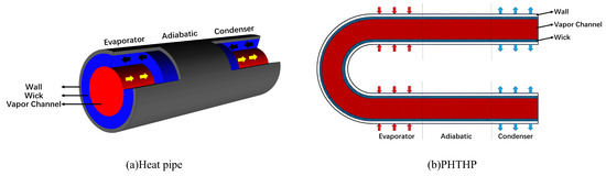
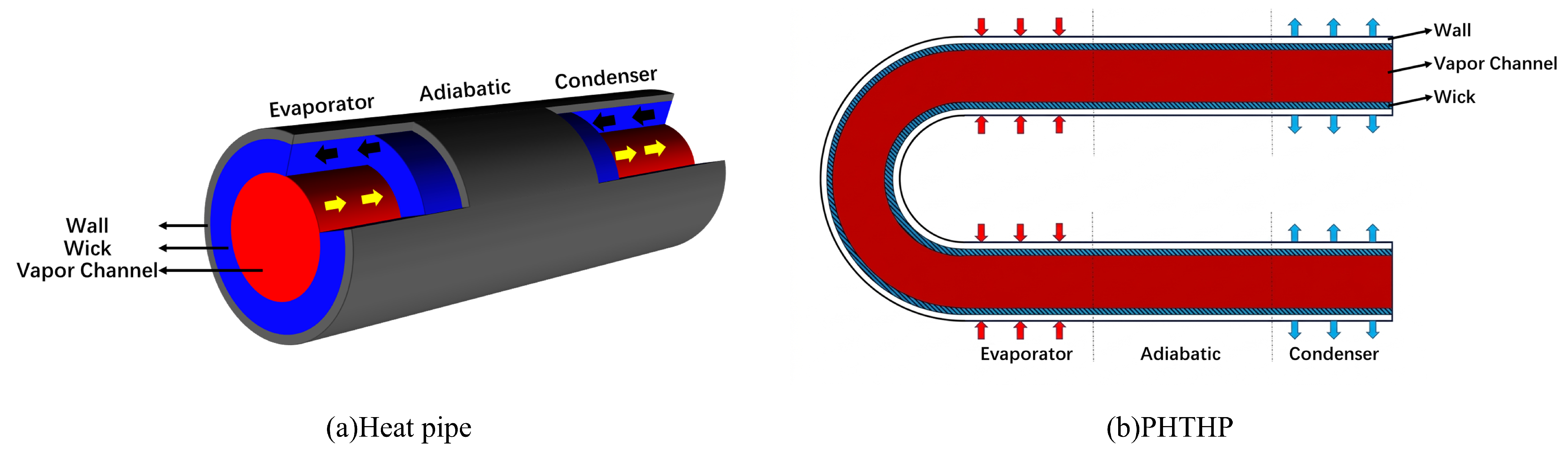
The operation of high-temperature alkali metal heat pipes involves physical processes such as the flow of vapor and liquid working fluids, phase change, heat transfer across the vapor–liquid interface, and heat conduction between the wall and the wick of the heat pipe. It is a highly coupled multiphysics process. Along the axial direction, the heat pipe can be divided into the evaporation section, adiabatic section, and condensation section. The alkali metal working fluid absorbs latent heat and evaporates in the evaporation section. Driven by a pressure difference, the vapor flows to the condensation section, where it condenses and releases heat. The liquid working fluid returns under the action of capillary force in the wick. The working principle is shown in Figure 1a. To accurately capture the multiphysics interactions in a parallel configuration with curved pipe connections, a three-dimensional numerical model was established, and the governing equations were solved using a three-dimensional Cartesian coordinate system. The commercial CFD software Ansys Fluent 2020R2 [27] was used for the simulations. The heat pipe wall material is stainless steel. The liquid and vapor working fluids flow in laminar regimes within the porous wick and the vapor channel, respectively, as shown in Figure 1b. To better represent the actual phase-change process, a thin boundary-layer mesh was applied at the vapor–liquid interface, and a UDF was used to restrict evaporation and condensation to occur only at the interface. Mass and energy source terms were used to simulate the heat and mass transfer processes. The initial time step was set to 8 × 10⁻⁵ s, and the global Courant number was set to 2. A time step was considered converged when the scaled residual of the continuity equation decreased below 10−3, the scaled residuals of the other governing equations decreased below 10−6, and the monitored temperature and pressure values remained stable during the iterative solution of the current time step.The geometric parameters of the PHTHP are summarized in Table 1.
Figure 1.
Structure and working principle of (a) a heat pipe and (b) the PHTHP.
Table 1.
Geometric dimensions of the PHTHP.
2.1. Multiphase Flow and Phase Change
To accurately capture the dynamic morphology of the vapor–liquid interface and the phase-change process, the VOF multiphase flow model was selected for the three-dimensional numerical simulation of the PHTHP. In the two-phase flow model, the volume fraction of the working fluid in each computational cell satisfies
When solving the governing equations in the wick and vapor channel regions, the phase volume fractions are used to calculate the thermophysical properties of the mixture through weighted averaging.
The CSF Model [28] treats interfacial surface tension as an equivalent body force for solving the momentum equation, expressed as
The Lee model [29] reflects the phase-change mechanism of evaporation and condensation based on local thermodynamic nonequilibrium, and the transport equation for the vapor phase is expressed as
Based on the relationship between the temperatures of each phase within the computational cell and the saturation temperature, the type of phase change occurring can be determined. The evaporation and condensation coefficients in these source terms were set to 1 and 500, respectively. By using UDFs to add mass source terms and energy source terms (as referenced in Table 2) to the continuity equations and energy equations of the liquid phase in the wick and the vapor phase in the vapor channel respectively, accurate simulation of the evaporation–condensation heat and mass transfer process is achieved.
Table 2.
Source terms implemented through UDFs in the PHTHP model.
2.2. Porous Wick
In Fluent, the porous media model does not create volume blockage; instead, it simulates the resistance experienced by the liquid working fluid flowing within the wick region by adding source terms to the momentum equations. The porous media momentum source term consists of a Darcy viscous loss term and an inertial loss term:
For a simple homogeneous porous medium, the momentum source term can be simplified as
In the porous media model, the viscous resistance, 1/, characterizes the linear pressure loss caused by viscous effects as the working fluid passes through the porous wick, and its reciprocal corresponds to the permeability . The inertial resistance coefficient characterizes the nonlinear pressure loss associated with inertial effects at higher flow velocities. In this study, the viscous and inertial resistance coefficients were obtained by fitting the pressure gradient as a function of superficial velocity using the results of separate flow calculations for the wick structure. The structural parameters of the wick and the fitted porous media model parameters used in the simulations are summarized in Table 3.
Table 3.
Porous media model parameters of the stainless-steel screen wick.
The porous media model includes both the porous stainless-steel wick and the liquid alkali metal working fluid. Therefore, the effective thermal conductivity of this region is jointly determined by these two materials, and the expression for calculating the effective thermal conductivity [30] is
In addition, the flow of liquid metal working fluid in the wick region is also influenced by capillary forces. According to the Young–Laplace equation, the capillary pressure [31] under the idealized complete-wetting assumption can be expressed as
where is the surface tension coefficient and is the effective pore radius of the wick.
The capillary force is added as a body force to the source term of the axial momentum equation in the porous wick region:
where denotes the axial coordinate, is the derivative of surface tension with respect to temperature, and is the local axial temperature gradient. The axial variation in capillary pressure arises from the variation in surface tension with temperature. The UDF reads the local axial temperature gradient in each computational cell and uses it to update the capillary momentum source during each iteration.
2.3. Governing Equations
The heat transfer on the solid wall surface of the heat pipe satisfies
The continuity equation in the wick region is
The momentum equation in the wick region:
The energy equation in the wick region:
The continuity equation in the vapor channel region:
The momentum equation in the vapor channel region:
The energy equation in the vapor channel region:
2.4. Boundary Conditions and Physical Properties
The evaporator of the heat pipe is heated with a uniform boundary heat flux:
The convective boundary condition of the condenser is
The adiabatic section and the bent connecting section on the outer wall of the heat pipe are maintained as adiabatic:
According to the no-slip boundary condition, the boundaries at the end caps of the PHTHP are set to be adiabatic with zero velocity:
In addition, the PHTHP model in this paper uses potassium as the working fluid for numerical simulation, and the relevant thermophysical properties of potassium are shown in Table 4 (the applicable temperature range of the correlations is 800–1300 K).
Table 4.
Physical properties of potassium.
3. Methodology Validation
In order to ensure that the numerical model of the PHTHP established in this study possesses sufficient physical credibility and numerical reliability, validation of the model is required before analyzing its operating characteristics. This section conducts the evaluation from two aspects: first, by comparing the numerical results with existing experimental data for a single straight potassium heat pipe to verify the model’s ability to reconstruct the heat transfer behavior of high-temperature alkali metal heat pipes; second, by performing a mesh independence analysis to examine the sensitivity of the computational results to discretization scale, thereby determining a mesh scheme that balances computational accuracy and cost.
3.1. Experimental Validation
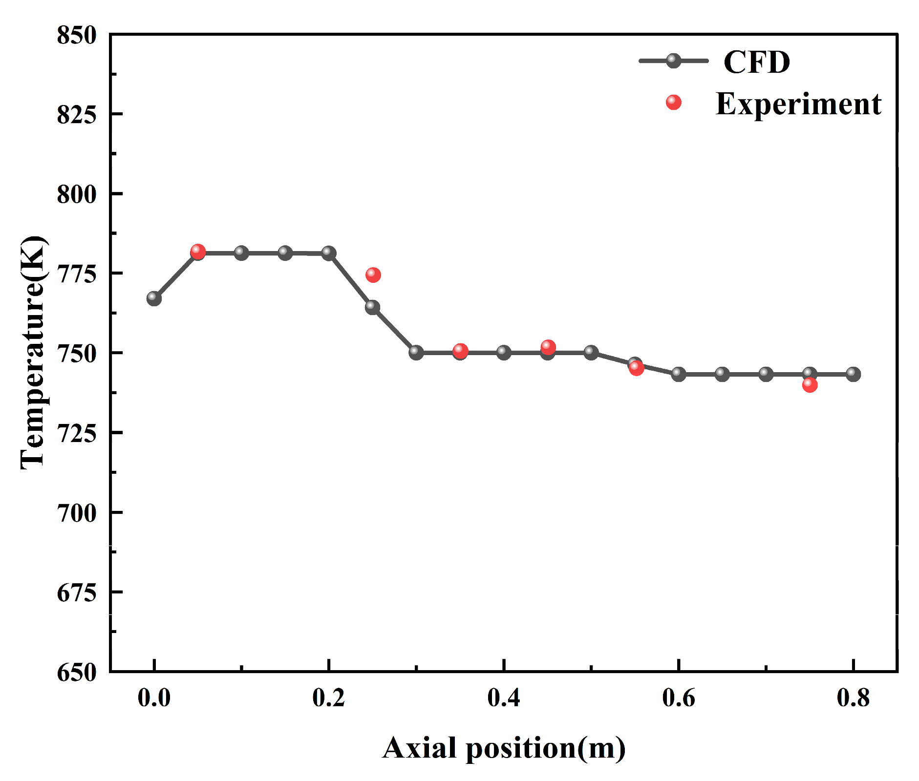
To verify the predictive capability of the developed numerical model for the heat transfer behavior of high-temperature alkali metal heat pipes, the experimental results of a single potassium heat pipe reported by Sun et al. [19] were selected as a reference. In that experiment, the axial wall temperature distribution of the heat pipe was measured under an input power of 770 W. The geometric parameters were as follows: the lengths of the evaporator, adiabatic, and condenser sections were 250 mm, 300 mm, and 250 mm, respectively, while the diameters of the wall, wick, and vapor channel were 30 mm, 24 mm, and 14 mm. To ensure a rigorous comparison, the straight-pipe section in the PHTHP numerical simulation adopted the same geometric dimensions and thermal boundary conditions as in the experiment.
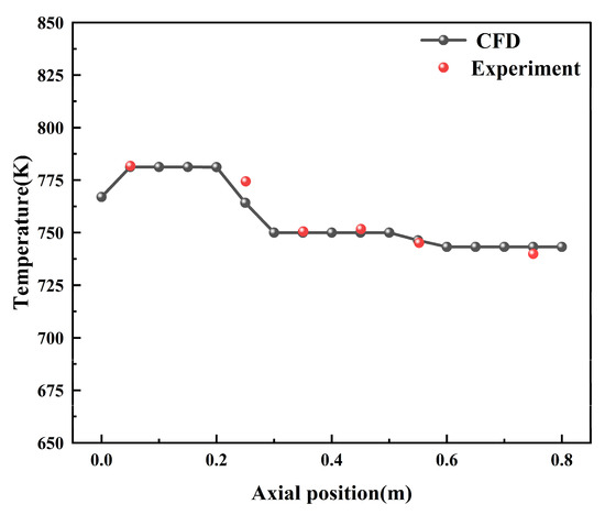
A comparison between the experimental data and simulation results shows that, as illustrated in Figure 2, the numerical model used in this study can accurately reproduce the axial temperature distribution characteristics of the potassium heat pipe. Quantitative evaluation indicates that the root mean square error predicted by the model is 4.47 K, and the average relative error is 0.384%. Considering that the interior of high-temperature alkali metal heat pipes involves coupled processes such as vapor compressible flow, liquid return flow through porous media, and vapor–liquid phase change, the above level of error demonstrates that the numerical model possesses high predictive accuracy. The validation indicates that the present model can reasonably reproduce the main heat transfer behavior of a high-temperature potassium heat pipe. Although direct experimental validation of the proposed parallel configuration is not yet available, the validated straight-pipe model provides a physically credible basis for the subsequent comparative analysis of the coupled configuration. Therefore, the present validation confirms the basic phase-change heat transfer capability of a single high-temperature potassium heat pipe, and the following analyses of the parallel configuration are comparative predictions based on this validated baseline model.
Figure 2.
Axial wall temperature distribution of the straight potassium heat pipe compared with experimental data.
3.2. Mesh Independence Verification
To evaluate the independence of the computational results from the mesh scale and to determine a suitable discretization scheme for subsequent simulations, a mesh independence verification is conducted in this section. Considering that the PHTHP includes solid walls, a porous wick structure, a vapor channel, and a bent connecting section, the geometry is relatively complex and involves conjugate heat transfer and multiphase flow coupling processes. Therefore, mesh quality has a significant impact on numerical stability and result accuracy.
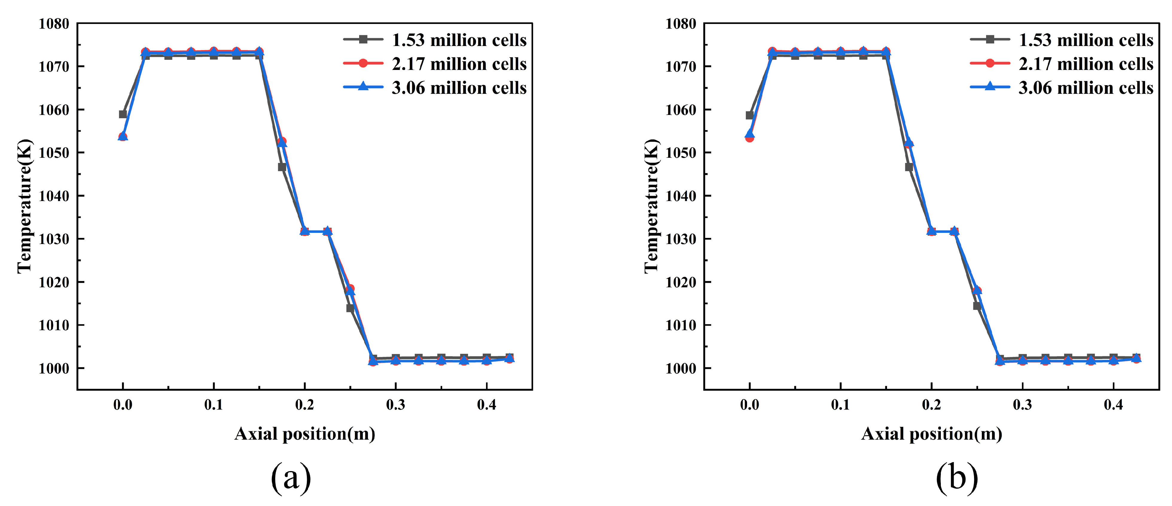
In this study, ANSYS ICEM CFD [32] is used for mesh generation. A globally conformal hexahedral mesh is adopted to ensure consistency at the conjugate heat transfer interfaces. An O-grid strategy is introduced in the multilayer tubular regions to enhance mesh orthogonality and improve discretization quality near complex curved surfaces. The axial wall temperature distributions of heat pipe a and heat pipe b in the parallel configuration are selected as evaluation metrics, and three different mesh sizes are compared, with element counts of 1,531,780, 2,166,900, and 3,058,281, respectively. The comparison results, as shown in Figure 3a,b, indicate that when the mesh number increases from 1,531,780 to 2,166,900, the predicted wall temperature distributions change noticeably. However, when the mesh is further refined to 3,058,281, the axial wall temperature curves of both heat pipe a and heat pipe b almost coincide with those obtained using 2,166,900 elements, indicating that the results have reached mesh independence. Considering both computational accuracy and resource consumption, a mesh with 2,166,900 elements is ultimately selected as the standard mesh for subsequent simulations.
Figure 3.
Mesh-independent analysis for the PHTHP: (a) pipe a and (b) pipe b.
4. Results and Discussion
This section focuses not only on comparing temperature and pressure responses under different operating conditions, but also on elucidating how inter-pipe coupling within the parallel configuration is associated with heat redistribution under non-uniform thermal loads and heat transfer under an idealized single-pipe failure condition. In this sense, the following analyses are intended to clarify the thermal and hydrodynamic role of the proposed coupling mechanism under thermal, structural, and failure-related disturbances.
4.1. Baseline Operating Characteristics Under Symmetric Conditions
To clarify the fundamental operating behavior of the PHTHP under ideal symmetric boundary conditions and to establish a common reference state for the subsequent disturbance analyses, a systematic analysis was first conducted on its temperature field distribution, transient thermal response, and vapor flow characteristics. Under this condition, the structural parameters and boundary conditions of the two straight pipes are identical, and the numerical results define the undisturbed thermal and hydrodynamic state of the PHTHP, against which changes in temperature, inter-pipe pressure difference, and vapor flow are evaluated in Section 4.2, Section 4.3 and Section 4.4.
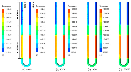
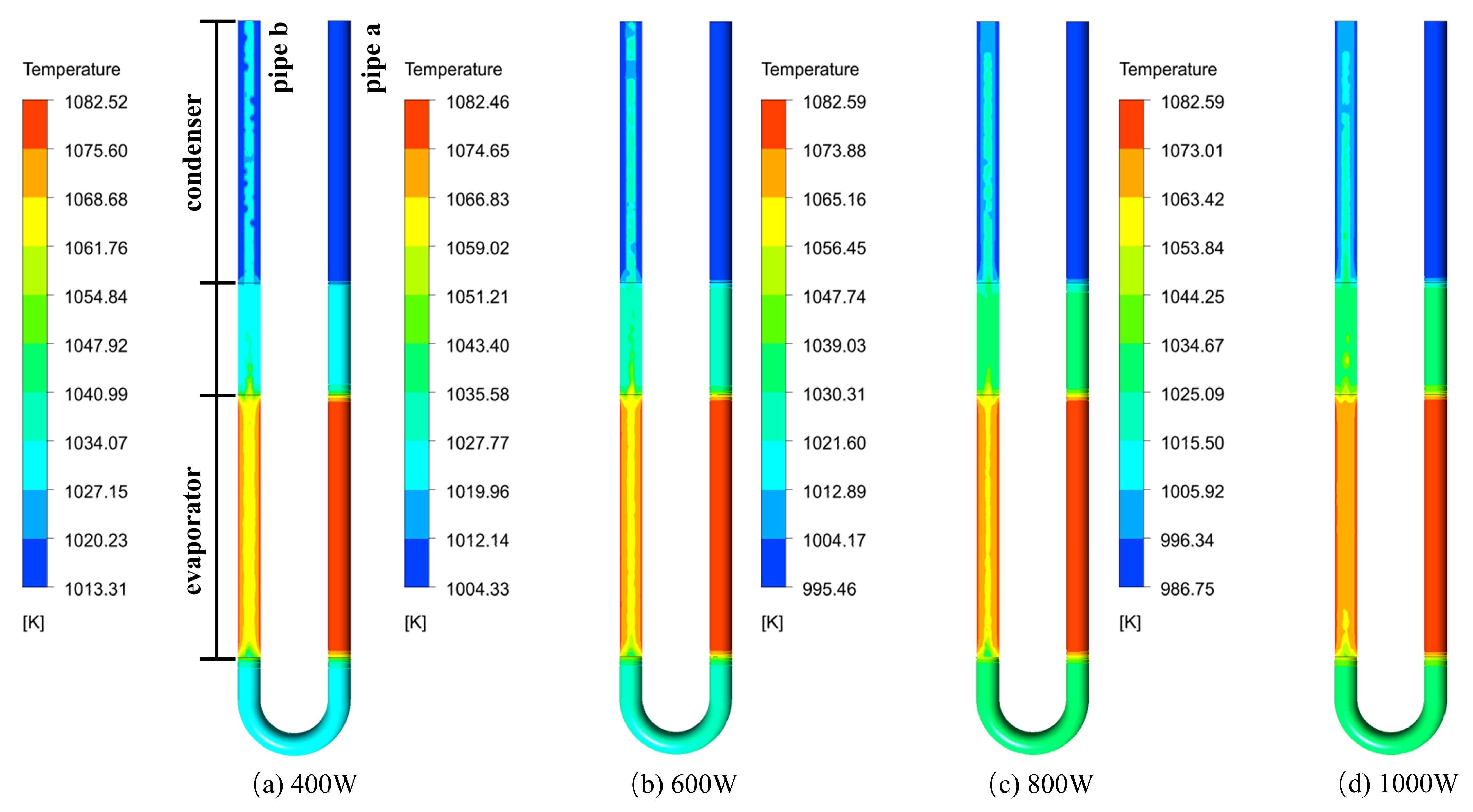
Figure 4a–d presents the 3D temperature field under 400–1000 W cooling powers, using a dual-perspective visualization strategy: pipe a shows the outer wall temperature, while pipe b shows the internal cross-sectional distribution. At a cooling power of 600 W, the three-dimensional temperature field of the system exhibits typical operating features of high-temperature heat pipes. From the temperature contours, it can be observed that both parallel straight pipes maintain good temperature uniformity within their respective evaporation, adiabatic, and condensation sections, indicating that the internal evaporation–condensation cycle has been stably established. The outer wall temperature distribution corresponds well with the internal cross-sectional temperature distribution, clearly reflecting the radial heat transfer process from the outer wall, through the porous wick, to the vapor–liquid interface. Compared with the outer wall, the axial temperature difference within the vapor channel is significantly smaller, demonstrating the strong isothermal heat transfer capability of the vapor working fluid due to latent heat of phase change, which is one of the main reasons why high-temperature alkali metal heat pipes can achieve efficient heat transfer.
Figure 4.
Temperature distributions of the PHTHP under different cooling powers.
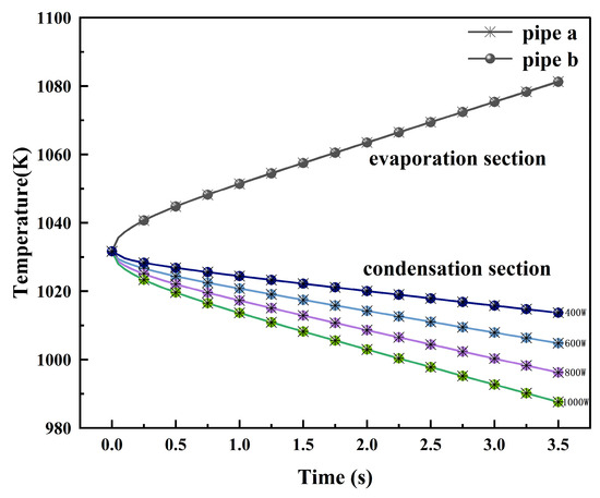
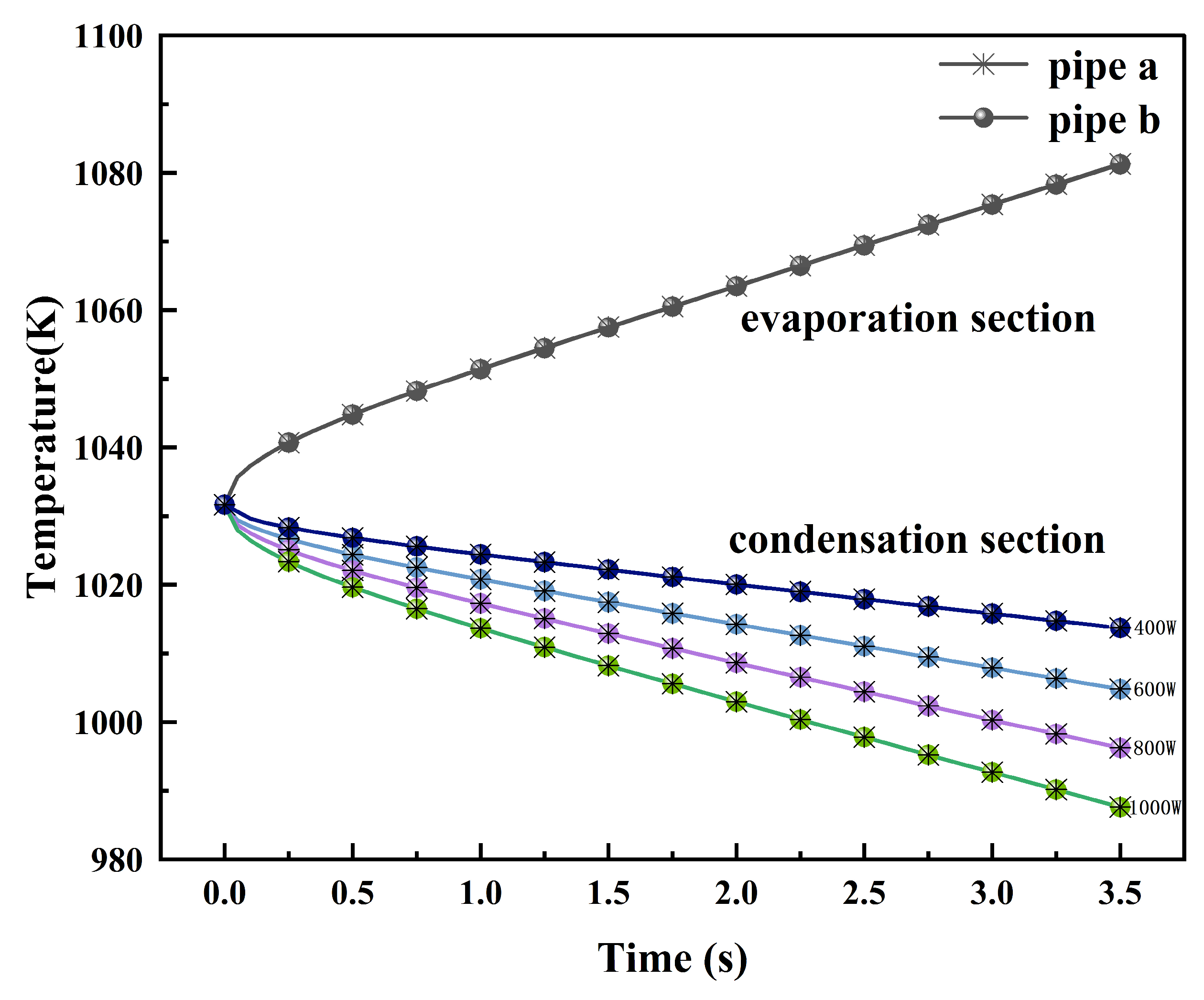
Under different cooling intensities, the transient thermal response of the system further reveals the evolution process by which the PHTHP reaches quasi-steady operation. Figure 5 shows the transient thermal response characteristics of the PHTHP under different cooling powers. Initially, the system maintains an isothermal state. Driven by boundary conditions, the wall temperature of the evaporation section increases monotonically with heat accumulation, while the wall temperature of the condensation section decreases monotonically at different rates. As time progresses, the slopes of the temperature curves under all conditions gradually decrease and eventually flatten, indicating that the internal heat transfer mechanism transitions from initial thermal inertia accumulation to a quasi-steady heat transfer process dominated by the evaporation–condensation phase-change cycle. Variations in cooling intensity determine the heat transfer rate in the condensation section and also reflect the consistent response trend of the PHTHP, demonstrating that this configuration exhibits stable thermal response characteristics under symmetric conditions.
Figure 5.
The average wall temperatures of the PHTHP under different cooling powers.
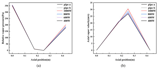
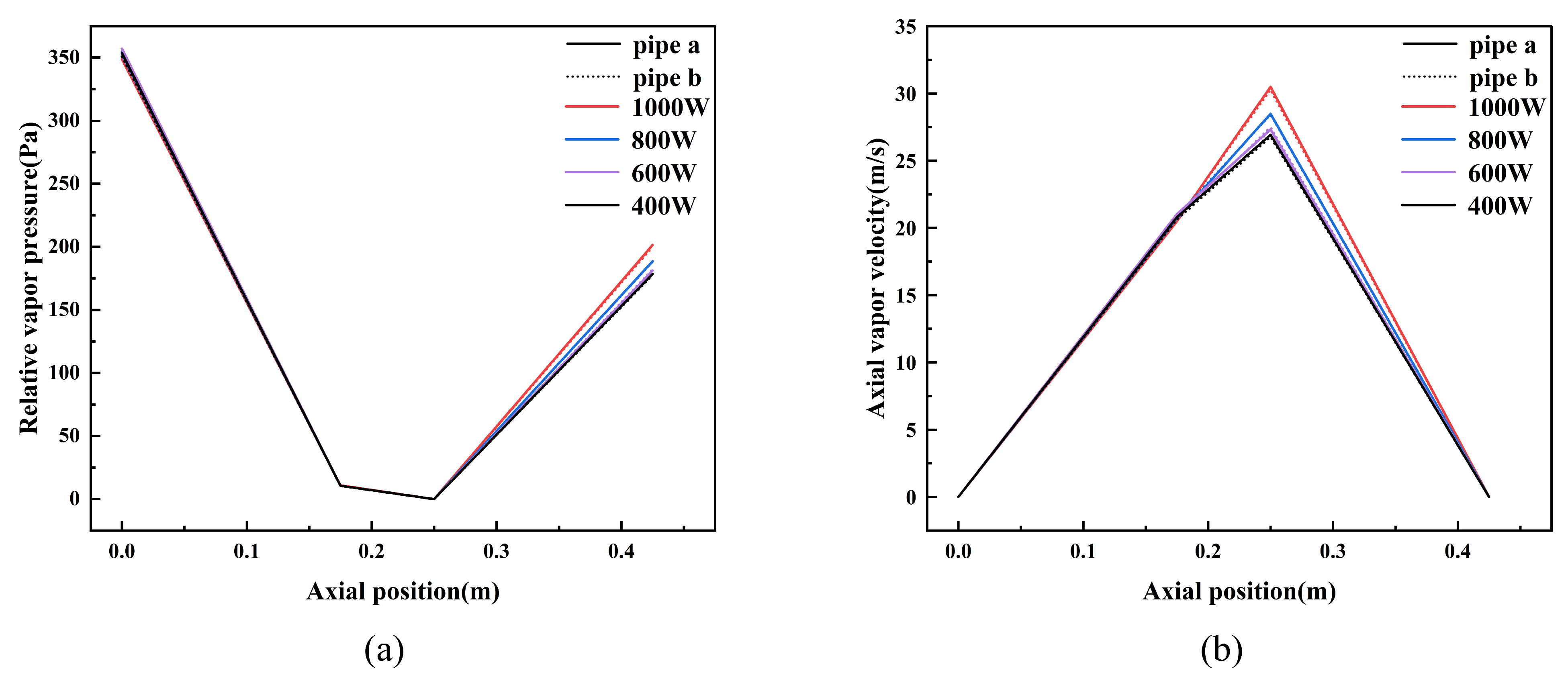
The axial pressure and velocity distributions along the centerline of the vapor channel further illustrate the internal flow mechanism. Figure 6a shows the axial pressure distribution along the centerline of the vapor channel in the PHTHP under different cooling intensities. For standardized representation, the vapor pressure at the end of the adiabatic section is used as the reference for normalization. The results indicate that the vapor pressure generally follows a trend of “decreasing first and then increasing” along the axial direction: it gradually decreases from the evaporation section, reaches a minimum at the end of the adiabatic section, and then increases gradually in the condensation section. This behavior is mainly determined by two factors: on the one hand, the vapor experiences continuous viscous resistance and local flow losses along the axial direction, leading to pressure loss; on the other hand, upon entering the condensation section, the vapor continuously condenses, resulting in a gradual decrease in vapor mass flow rate. With increasing cooling intensity, the condensation rate is significantly enhanced, causing a faster reduction in vapor mass flow rate in the condensation section, and thus a more pronounced pressure recovery.
Figure 6.
Distributions along the centerline of the vapor channel in the PHTHP under different cooling powers: (a) relative vapor pressure; (b) axial vapor velocity.
Corresponding to the pressure distribution, the axial vapor velocity reaches relatively high levels in the evaporation and adiabatic sections and gradually decreases in the condensation section. Figure 6b shows the axial velocity distribution along the centerline of the vapor channel under different cooling intensities. Stronger cooling enhances the vapor circulation intensity, and therefore the peak axial vapor velocity exhibits a clear positive correlation with cooling power. Under the 1000 W cooling condition, the maximum vapor Reynolds number was approximately 1900 and occurred near the midpoint of the adiabatic section. Since different cooling conditions correspond to different convective heat transfer coefficients, these four symmetric cases also constitute a sensitivity analysis of the condenser-section wall convective heat transfer coefficient . The results show that, as increases, the average wall temperature of the condenser section decreases from approximately 1013 K to 987 K, while the peak axial vapor velocity increases from approximately 27 m/s to 30 m/s. However, the two heat pipes still exhibit nearly identical temperature, pressure and velocity distributions under all operating conditions. Therefore, affects the flow and heat transfer characteristics of the system, but does not alter the main conclusion that the parallel configuration operates symmetrically and stably. Within the unified numerical framework, the temperature deviations, inter-pipe pressure differences, and vapor-flow responses induced by non-uniform thermal loading; an idealized single-pipe failure condition; and adiabatic-section bending are subsequently quantified relative to this reference.
4.2. Flow and Heat Transfer Characteristics Under Non-Uniform Thermal Loads
In practical engineering applications, especially within the complex core environment of heat-pipe-cooled space nuclear reactors, heat pipes are often unable to operate under ideal symmetric conditions for extended periods. Due to factors such as uneven neutron flux distribution, local power fluctuations, and structural constraints, the thermal loads borne by individual heat pipes often differ significantly. Non-uniform heating not only intensifies local temperature gradients and thermal stresses but may also weaken the operational stability of a single heat pipe. Therefore, this section examines the thermal and flow responses of the PHTHP under non-uniform heat loads, focusing on the temperature, pressure, and vapor flow associated with the connection between the two pipes.
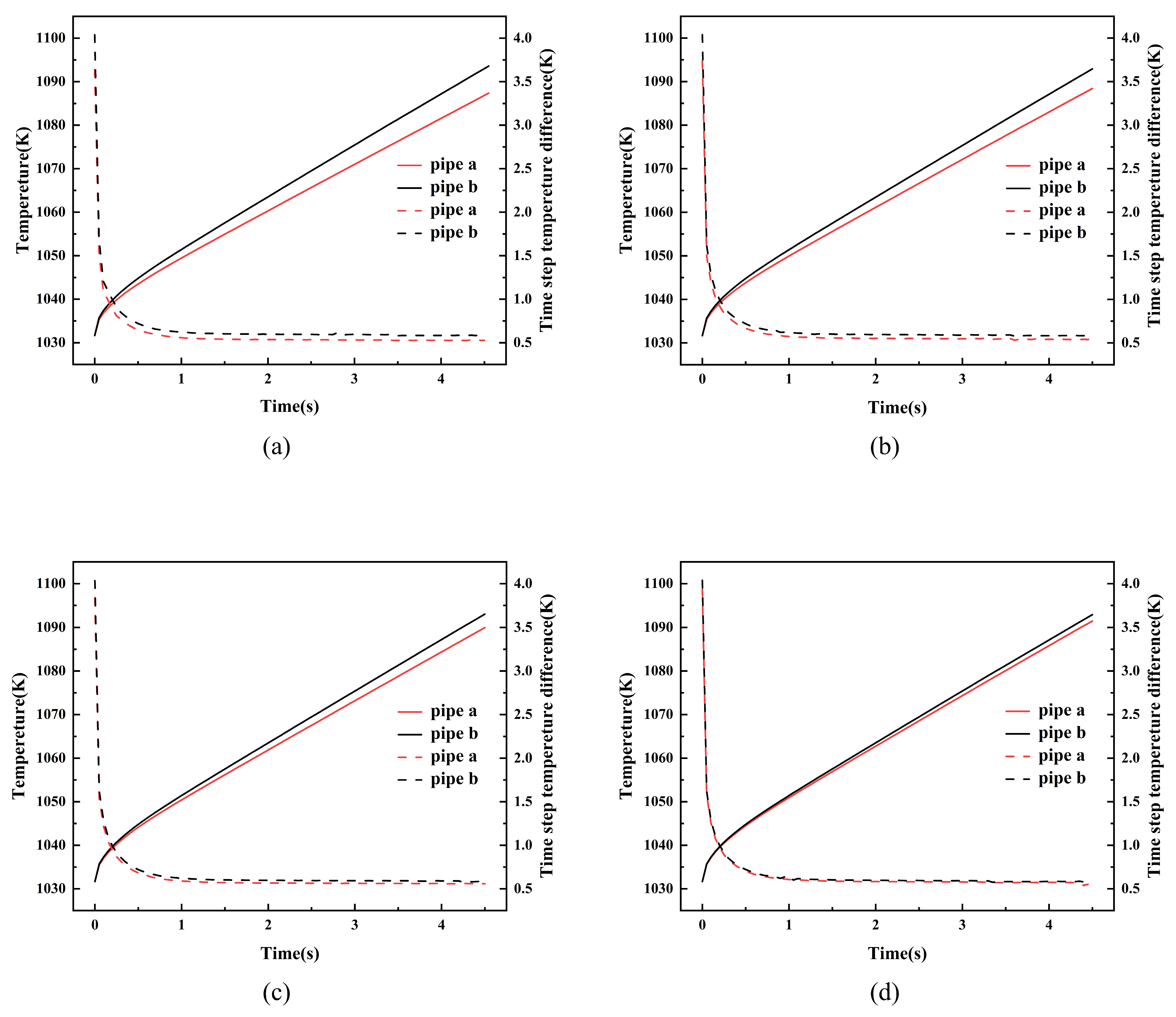
Under the conditions where the input power of pipe b is set to 1000 W and that of pipe a ranges from 900 to 975 W, the transient wall temperature variations in the evaporation sections of the two heat pipes exhibit a high degree of consistency, as shown in Figure 7. Despite a maximum input power deviation of 10%, the average temperature variation curves of the two pipes show good agreement, indicating that the temperatures of the two evaporation sections remain relatively close within the investigated range of non-uniform thermal loads. When the local heat input varied, changes in temperature were calculated in both pipes. The right y-axis represents the temperature change rate (dT/dt) at each time step, which also reflects the heat transfer characteristics of the PHTHP. In the early stage of simulation, due to the stepwise application of heat flux, the system’s temperature change rate exhibits short-term fluctuations. However, under all operating conditions, the temperature change rates of both pipes rapidly stabilize within 1 s and eventually converge to nearly the same level. This demonstrates that the parallel configuration can also quickly transition from transient disturbances to quasi-steady operation. Although non-uniform heat loads broke the symmetry of the input conditions, the temperatures and their rates of change in the two evaporation sections remained relatively close within the investigated range.
Figure 7.
The average wall temperatures and time-step temperature differences in the evaporation sections of the PHTHP under non-uniform thermal loads. The input power of pipe b is fixed at 1000 W, while that of pipe a is: (a) 900 W; (b) 925 W; (c) 950 W; (d) 975 W.
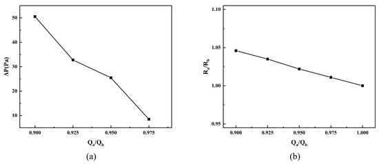
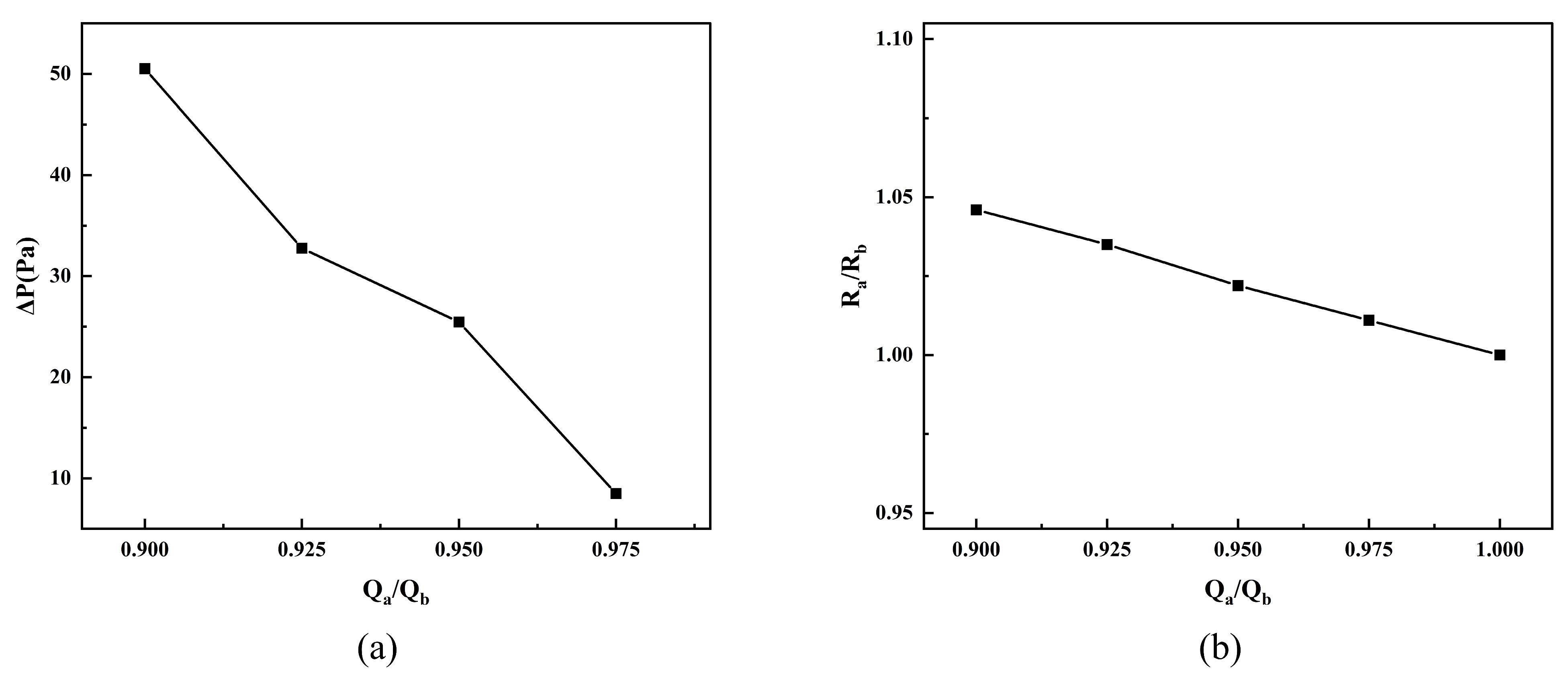
The pressure distribution of the PHTHP also changed under non-uniform heat loads. As shown in Figure 8a, a significant local pressure gradient is established between the two evaporator sections in the PHTHP, breaking the original isobaric equilibrium state. The reason is that the side with a higher thermal load has a higher evaporation rate and generates more local vapor, leading to an increase in vapor pressure; on the side with a lower thermal load, the phase-change intensity is relatively weaker and the pressure level is correspondingly lower, ultimately establishing a pressure difference between the two pipes. Numerical results indicate that the inter-pipe pressure difference is strongly positively correlated with the degree of asymmetry in input power. When the input power deviation is 10%, the pressure difference between the pipes can increase to about 50 Pa. Within the present numerical model, the predicted pressure differences suggest that localized vapor transfer may occur between the two pipes under non-uniform heat loads.
Figure 8.
(a) The relationship between the inter-pipe pressure differences and the input power ratio; (b) the relationship between the inter-pipe thermal resistance ratio and the input power ratio.
The equivalent thermal resistance of the heat pipe can be calculated using Equation (26). Since thermal resistance essentially reflects the strength of heat transfer capability, minimizing the deviation in thermal resistance among heat pipes in the array is crucial for maintaining the overall thermal efficiency of the system. Thermal resistance has also been widely adopted in previous numerical studies as an integral indicator for evaluating the overall heat transfer performance and effective thermal conductivity of two-phase heat transfer devices. For example, Zhang et al. [33] analyzed the thermal resistance of porous wick flat micro heat pipes under various operating conditions, while Kim and Moon [34] numerically investigated the relationship between thermal resistance and effective thermal conductivity in a two-phase thermosyphon.
where is the equivalent thermal resistance of a heat pipe, is the input power of the heat pipe, is the average temperature of the evaporator section, and is the average temperature of the condenser section.
From a macroscopic performance perspective, the relationship between the inter-pipe thermal resistance ratio and the input power ratio further indicates that the two pipes exhibit similar heat transfer performance. Figure 8b shows the relationship between the inter-pipe thermal resistance ratio (Ra/Rb) and the input power ratio (Qa/Qb). The calculation results indicate that as the input power deviation increases, although there is some difference in the equivalent thermal resistance between the two pipes, the overall variation remains small. When the input power ratio decreases to 0.9, the deviation in the equivalent thermal resistance ratio is still strictly controlled within 4.6%. This indicates that the PHTHP has low sensitivity to non-uniform input power and that the difference in overall heat transfer performance between the two heat pipes is small. For comparison, the corresponding relative difference in equivalent thermal resistance between two independent heat pipes is 5.6% at the same simulation time and under the same thermal boundary conditions. The PHTHP also exhibits a systematic reduction in this relative difference compared with the uncoupled configuration across the investigated range of input power ratios.
4.3. Flow and Heat Transfer Characteristics Under an Idealized Single-Pipe Failure Condition
In the critical mission environment of heat-pipe-cooled space nuclear reactors, thermal management systems often face unpredictable single-point failures during long-term operation. Such failures may arise from the accumulation of non-condensable gases, local dry-out caused by reaching the capillary limit during startup, or structural damage due to micrometeoroid impacts. For heat pipes, these typically manifest as a significant increase in local radial thermal resistance and an interruption of the internal evaporation-condensation phase-change cycle. To characterize the thermal and flow responses of the PHTHP under severe local degradation, this study simulates an idealized single-pipe failure condition, in which the thermal resistance of one heat pipe increases significantly and its internal phase-change source terms are disabled.
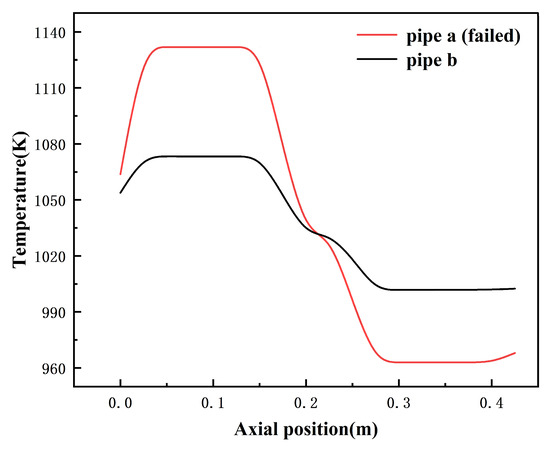
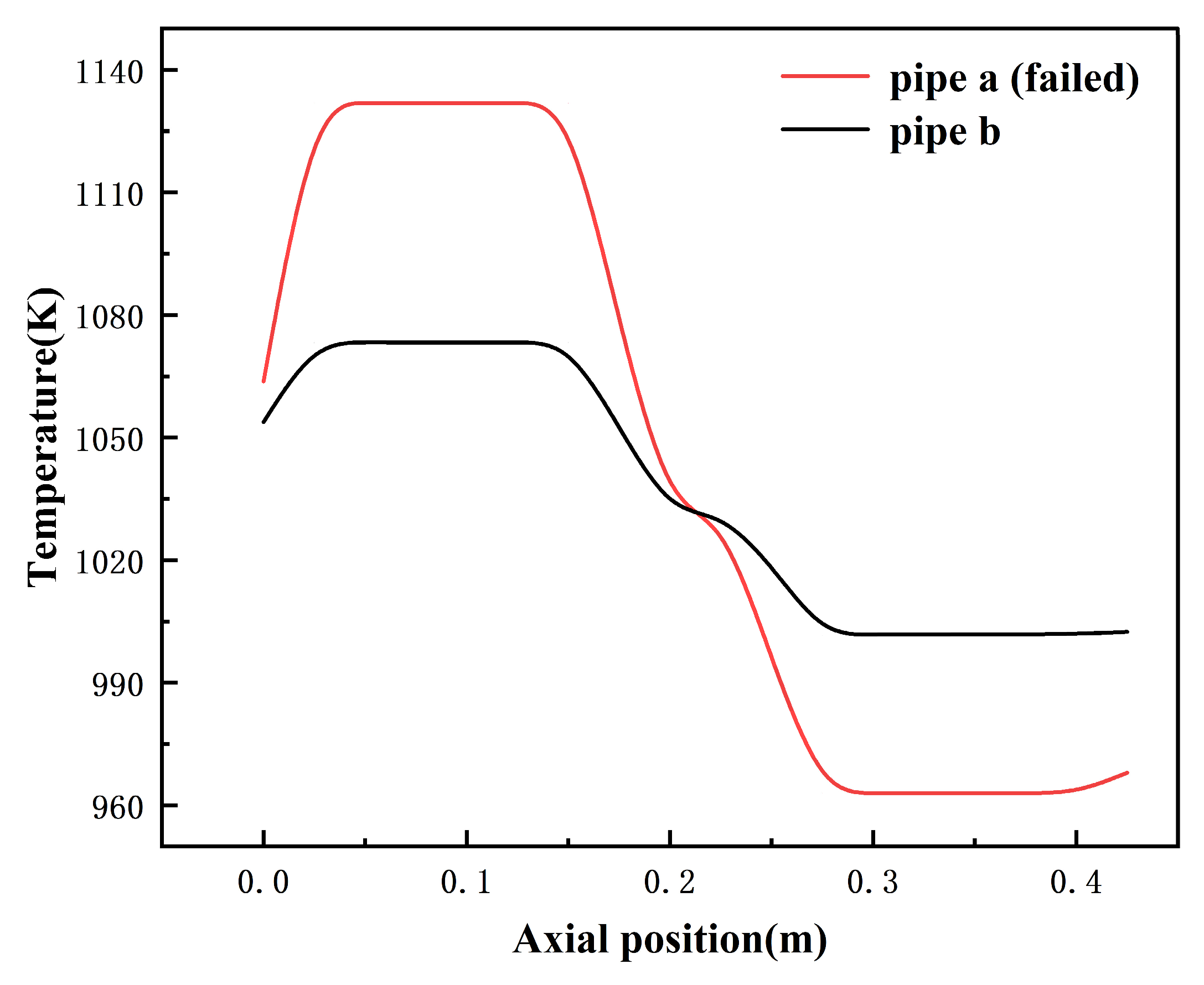
Under this idealized single-pipe failure condition, the axial distribution of the system wall temperature first reflects clear failure characteristics. Figure 9 shows the axial variation curve of the system wall temperature under the idealized single-pipe failure condition. Numerical results indicate that, due to the increase in radial thermal resistance, significant heat accumulation occurs at the evaporation section wall of pipe a, with an average temperature reaching as high as 1137.52 K, approximately 64.31 K higher than that of the normally operating pipe b. Further equivalent thermal resistance analysis shows that the equivalent thermal resistance of the failed pipe a increases to 0.1782 K/W, about 2.49 times that of the normally operating pipe b (0.0716 K/W). It is evident that under this idealized single-pipe failure condition, the heat transfer capacity of the failed pipe decreases significantly, and the original symmetric operating state of the system is disrupted.
Figure 9.
The axial wall temperature distributions of the PHTHP under an idealized single-pipe failure condition.
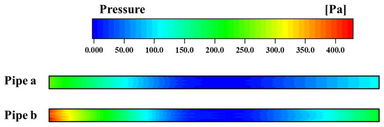
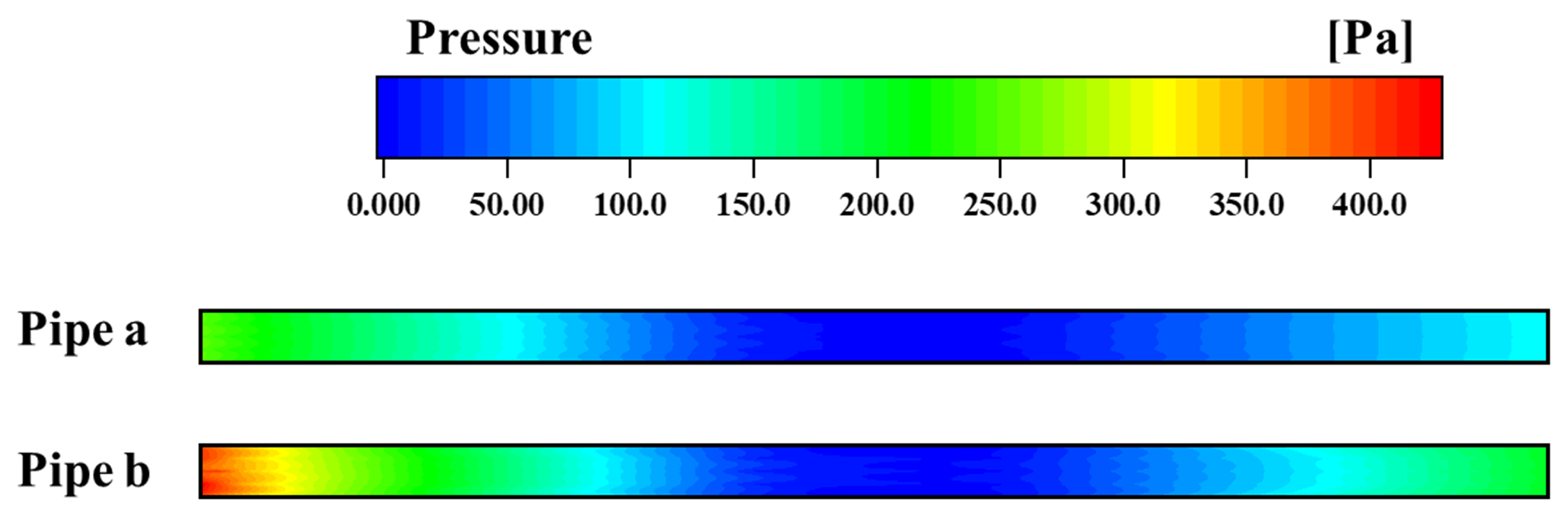
This asymmetry is also directly reflected in the pressure distribution. Figure 10 presents the axial pressure distribution contours of pipes a and b under the idealized single-pipe failure condition. The normally operating heat pipe b still maintains a complete evaporation-condensation phase-change cycle, with a pressure drop of about 375 Pa between the evaporation section and the adiabatic section. In contrast, due to the obstruction of internal phase change in the failed heat pipe a, a large amount of heat accumulates on the wall, and the temperature of the internal working fluid is significantly lower than in normal operation, resulting in a relatively flatter axial pressure profile. The numerical model predicts that a pressure difference of about 131.06 Pa forms between the evaporation sections of the two pipes, which also constitutes the main pressure drop as the vapor flows through the bent connecting section. These results characterize the predicted pressure and flow responses of the PHTHP under the idealized single-pipe failure condition.
Figure 10.
The axial vapor pressure distribution contours of the PHTHP under the idealized single-pipe failure condition.
4.4. Heat Transfer Characteristics Under Adiabatic-Section Bending Conditions
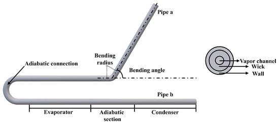
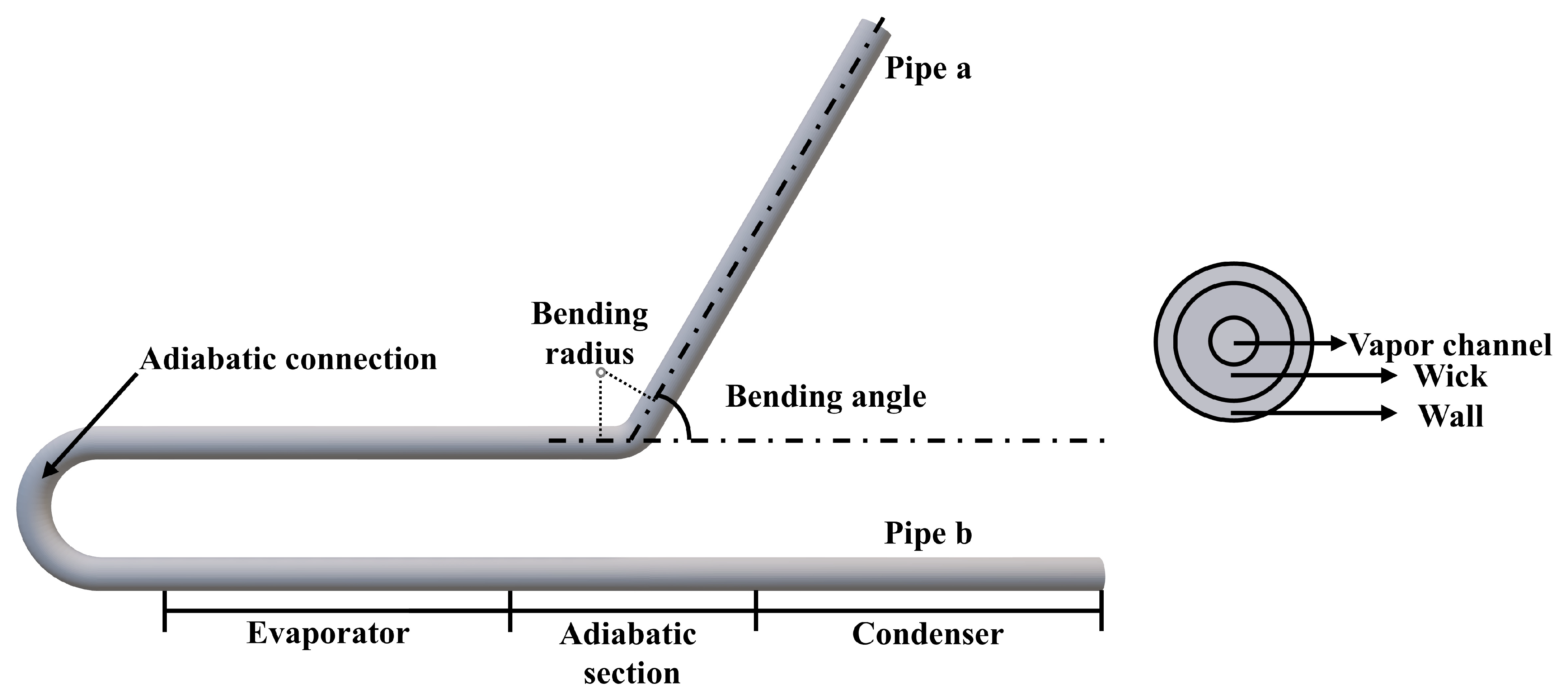
In practical engineering layouts, the adiabatic section of a high-temperature heat pipe cannot always remain perfectly straight because of compact integration requirements and space constraints. It is therefore necessary to evaluate the effect of local bending on the quasi-steady heat transfer performance of the PHTHP. In this section, pipe a is bent in its adiabatic section with bending angles of 30°, 45°, 60°, 75°, and 90°, whereas pipe b remains unchanged, as shown in Figure 11. Steady-state simulations are performed under the same thermal boundary conditions as those of the baseline configuration in order to isolate the influence of geometric bending.
Figure 11.
Geometric model of the PHTHP under bending effect.
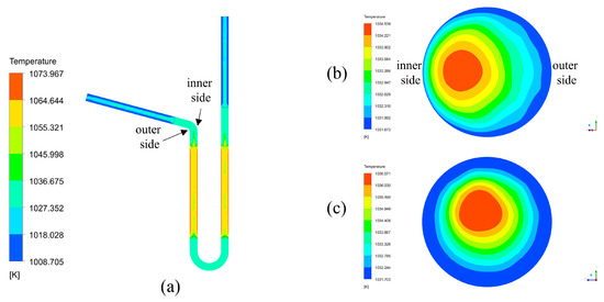
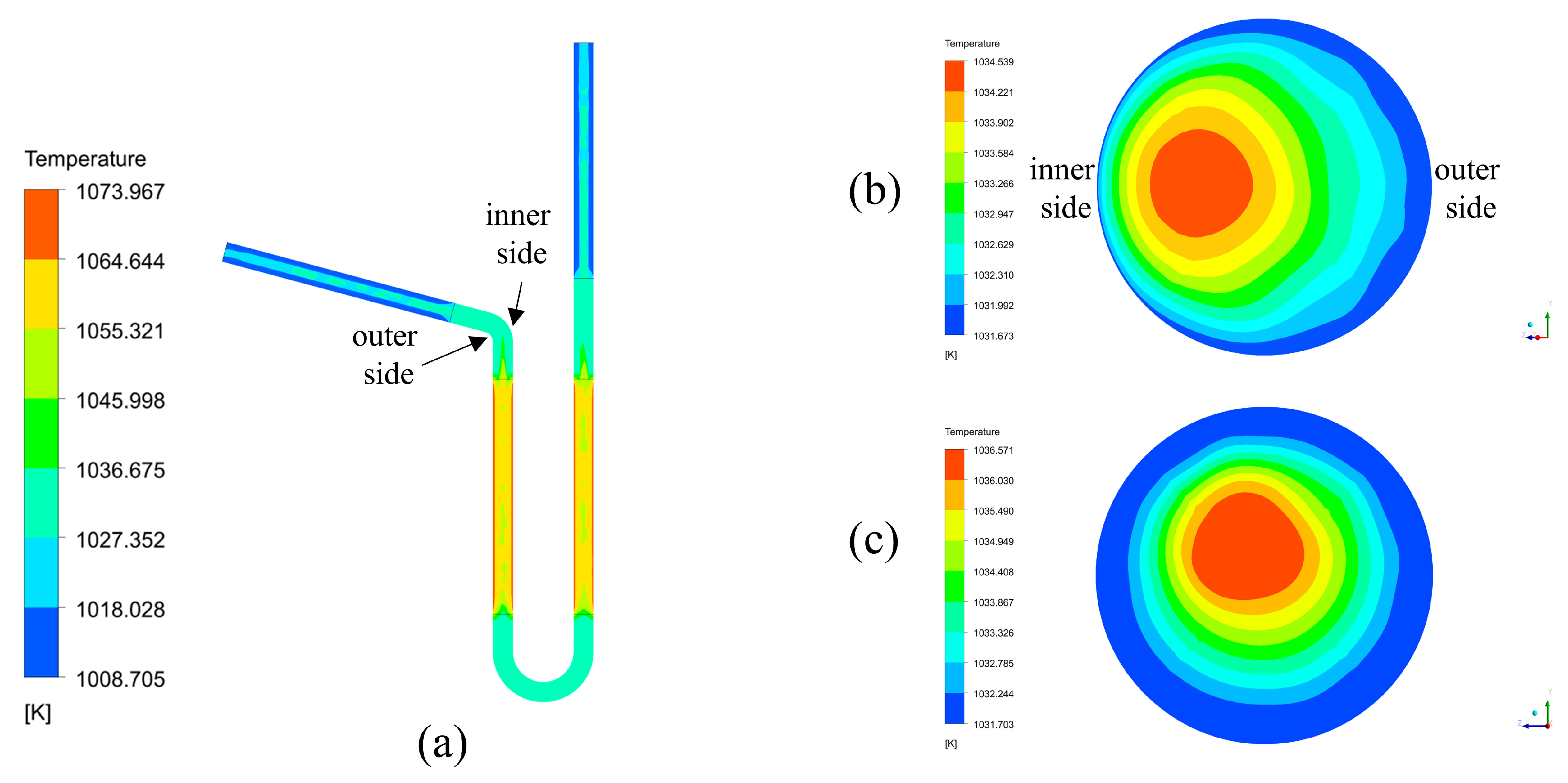
Figure 12a presents the temperature contours on the x-z plane of the PHTHP at a bending angle of 75°. In both heat pipes, the temperature decreases from the evaporator to the condenser, with the adiabatic section serving as a transition region. Compared with the regular contours in pipe b, those in pipe a become distorted near the bend, indicating a local redistribution of the temperature field. Nevertheless, the two heat pipes maintain similar overall temperature levels in the simulated cases.
Figure 12.
Temperature distributions of the PHTHP under 75° bending: (a) temperature contours on the x-z plane; vapor temperature contours at the midpoint cross sections of the adiabatic sections in (b) pipe a and (c) pipe b.
The vapor temperature is higher in the central region of the vapor channel and gradually decreases toward the interface between the vapor channel and the wick. This distribution reflects the coupling between axial energy transport by the vapor and radial conjugate heat transfer. Under the laminar flow assumption adopted in the present model, the central region of the vapor channel exhibits relatively stronger axial flow and heat transport. By contrast, vapor near the interface is more strongly affected by viscous effects, phase change at the vapor–liquid interface, and radial heat conduction through the wick.
The bending angle primarily changes the magnitude of the diametral temperature difference and the uniformity of the cross-sectional temperature field [22]. To compare the temperature fields of the bent and straight heat pipes, Figure 12b,c present the vapor temperature distributions at the midpoint cross sections of the adiabatic sections in pipe a and pipe b, respectively, at a bending angle of 75°. The temperature field in pipe b is approximately axisymmetric, with a maximum vapor temperature of 1036.571 K. By contrast, the region of maximum temperature in pipe a is displaced toward the inner side of the bend, and its maximum temperature is 1034.539 K, approximately 2.03 K lower than that in pipe b. The calculations for all bending angles show that the cross-sectional vapor temperature distribution in pipe a exhibits varying degrees of displacement relative to that in pipe b. The maximum cross-sectional vapor temperature in pipe a exceeds that in pipe b from 30° to 60°, whereas this relationship is reversed at 75° and 90°. This reversal indicates that the cross-sectional temperature response does not vary monotonically with bending angle within the investigated range. Previous three-dimensional simulations of bent high-temperature sodium heat pipes have shown that a radial pressure difference develops across the bend cross-section [35]. Because the vapor remains close to saturation, the local temperature non-uniformity can also give rise to a radial pressure difference through the dependence of saturation pressure on temperature.
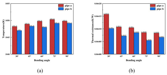
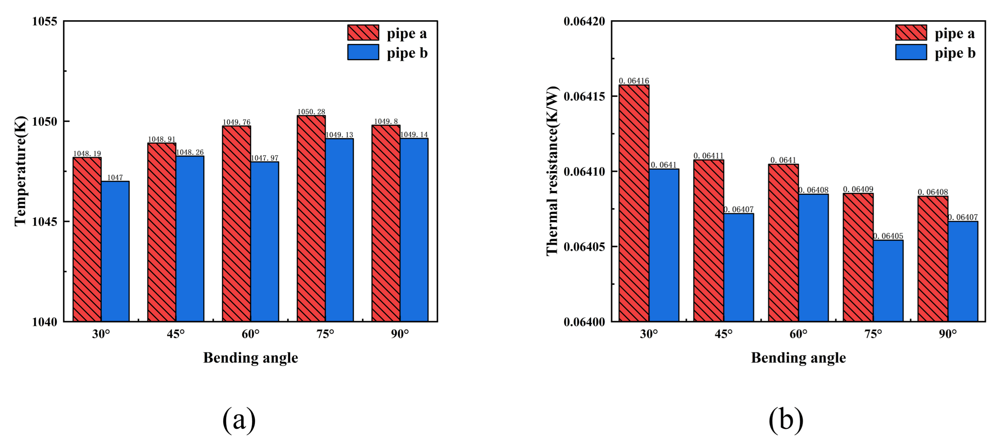
Figure 13a compares the vapor temperatures averaged over the inlet areas of the adiabatic sections in the two heat pipes. Pipe a maintains a higher inlet temperature than pipe b for all bending angles. Its inlet temperature generally increases from 30° to 75°, reaches a maximum at 75°, and then decreases slightly at 90°. Pipe b also exhibits a small but corresponding response to the bending angle of pipe a. In the numerical model, the vapor channel and wick domains are continuous through the connecting section. The model predicts that the bending disturbance in pipe a affects the temperature response of pipe b.
Figure 13.
Effects of bending angle on (a) the mean vapor temperatures at the inlets of the adiabatic sections and (b) the thermal resistance of the PHTHP.
Zhong et al. [36] conducted a comprehensive numerical investigation of a single high-temperature sodium heat pipe. As the bending angle increased from 0° to 45°, its thermal resistance increased from 0.03369 to 0.04683 K/W, corresponding to an increase of 39%. This result from the literature provides context but does not constitute an equivalent uncoupled reference for the present bending analysis. For the present PHTHP, Figure 13b shows that the thermal resistance of pipe a remains only slightly higher than that of pipe b, consistent with the additional transport resistance introduced by the local bend. The relative difference between the two pipes remains marginal across all bending angles. Unlike conventional heat pipe arrays, in which heat redistribution between adjacent pipes relies mainly on conduction through the solid reactor-core matrix, the present numerical model predicts direct hydraulic and thermal coupling between the two heat pipes through the continuous vapor channel and wick domains. The potential application of this parallel configuration to heat pipe arrays in engineering layouts requires further experimental evaluation. However, the small differences in thermal resistance between the two connected pipes do not establish that coupling reduces the effect of bending. Quantifying this contribution requires comparison with an equivalent uncoupled configuration under the same bending and thermal conditions.
5. Conclusions
This study investigated the thermal and hydrodynamic role of direct communication through the working fluid in a PHTHP. A three-dimensional VOF model was used to characterize the temperature, pressure, and vapor flow responses under a symmetric reference condition and three types of disturbance. The principal contribution is the integrated numerical characterization of the thermal and hydrodynamic responses under non-uniform thermal loading, an idealized single-pipe failure condition, and bending of the adiabatic section. The main conclusions are as follows:
- (1)
- Under symmetric conditions, the PHTHP can maintain stable operation. The two straight pipes show nearly identical distributions of wall temperature, vapor pressure, and axial flow velocity, exhibiting good isothermal heat transfer characteristics and isobaric balance. The vapor pressure first gradually decreases along the axial direction and then gradually increases in the condensation section. This distribution is mainly determined by flow resistance along the path and the decrease in vapor mass flow rate in the condensation section.
- (2)
- Under non-uniform heat load conditions, the temperatures and their rates of change in the evaporation sections of the two heat pipes remained relatively close within the investigated range. When the input power deviation was 10%, the pressure difference was approximately 50 Pa, and the relative difference in equivalent thermal resistance was 4.6%. These numerical results characterize the pressure and flow responses of the PHTHP under non-uniform heating conditions. Within the present numerical model, the pressure difference between the two pipes is accompanied by vapor flow through the connecting section.
- (3)
- Under an idealized single-pipe failure condition, the temperature distribution of the failed heat pipe deviates significantly from that of the normally operating pipe, and its equivalent thermal resistance increases to 2.49 times that of the normal pipe. This idealized condition significantly weakens local heat transfer capability and disrupts the original symmetric operating state of the system. The numerical model predicts vapor flow from pipe b to pipe a under the pressure difference between the two evaporation sections. These results characterize the thermal and flow responses of the PHTHP under the idealized single-pipe failure condition.
- (4)
- Under bending-effect conditions, pipe a exhibits a displaced vapor temperature distribution at the midpoint cross-section of the adiabatic section and a higher mean vapor temperature at the inlet of this section than pipe b. Nevertheless, the thermal resistances of the two heat pipes remain close over the investigated range of bending angles.
The present model considers only laminar vapor flow and uses an idealized geometry. No sensitivity analysis was conducted for the wick model parameters. The idealized single-pipe failure condition does not reproduce progressive failure processes, while validation is limited to a single straight potassium heat pipe. The predicted heat and mass transfer between the two pipes, including pressure-driven vapor transfer, remain experimentally unvalidated. No equivalent uncoupled reference cases were included for the idealized single-pipe failure or bending analyses; therefore, the contribution of the connection to mitigating failure or bending effects cannot be quantified under these conditions. Future work should assess different flow regimes and the sensitivity to wick model parameters; experimentally validate the parallel configuration; and investigate more realistic geometries, progressive failures, and representative engineering boundary conditions.
Author Contributions
Conceptualization, Q.Z. and M.W.; methodology, M.W.; software, M.W.; validation, M.W.; formal analysis, M.W.; investigation, M.W.; resources, Q.Z.; data curation, M.W.; writing—original draft preparation, M.W.; writing—review and editing, Q.Z.; visualization, M.W.; supervision, Q.Z.; project administration, Q.Z.; funding acquisition, Q.Z. All authors have read and agreed to the published version of the manuscript.
Funding
This research was funded by the Department of Science and Technology of Guangdong Province, grant number 2024A1515011441.
Data Availability Statement
The original contributions presented in this study are included in the article. Further inquiries can be directed to the corresponding author.
Conflicts of Interest
The authors declare no conflict of interest.
Abbreviations
The following abbreviations are used in this manuscript:
| NASA | National Aeronautics and Space Administration |
| LANL | Los Alamos National Laboratory |
| PHTHP | Parallel High-Temperature Heat Pipe |
| UDFs | User-Defined Functions |
| VOF | Volume Of Fluid |
| CSF | Continuum Surface Force |
| CFD | Computational Fluid Dynamics |
| Nomenclature | |
| Symbols | |
| volume fraction | |
| density (kg/m3) | |
| dynamic viscosity (Pa·s) | |
| thermal conductivity of the material (W/(m·K)) | |
| surface tension coefficient (N/m) | |
| interface curvature (1/m) | |
| velocity (m/s) | |
| volumetric mass transfer rates (kg/(m3·s)) | |
| temperature (K) | |
| velocity magnitude (m/s) | |
| velocity (m/s) | |
| viscous resistance matrix (1/m2) | |
| / | inertial resistance matrix (1/m) |
| Mesh number (1/in) | |
| permeability of the porous wick | |
| porosity of the porous wick | |
| pressure (Pa) | |
| specific heat capacity (J/(kg·K)) | |
| radius (m) | |
| length (m) | |
| input power (W) | |
| convective heat transfer coefficient (W/(m2·K)) | |
| // | velocity components (m/s) |
| equivalent thermal resistance (K/W) | |
| Subscripts | |
| liquid alkali metal working fluid | |
| vapor alkali metal working fluid | |
| solid | |
| effective | |
| from liquid to vapor | |
| from vapor to liquid | |
| saturation | |
| evaporator | |
| wall | |
| ambient | |
References
- Poston, D.I. The Heatpipe-Operated Mars Exploration Reactor (HOMER). AIP Conf. Proc. 2001, 552, 797–804. [Google Scholar] [CrossRef] [Scilit]
- Martin, J.J.; Reid, R.S. Sodium based heat pipe modules for space reactor concepts: Stainless steel SAFE-400 core. In Proceedings of the ICAPP ’04, Pittsburgh, PA, USA, 13–17 June 2004. Paper 4182. [Google Scholar]
- Poston, D.I.; Kapernick, R.J.; Guffee, R.M. Design and analysis of the SAFE-400 space fission reactor. AIP Conf. Proc. 2002, 608, 578–588. [Google Scholar] [CrossRef] [Scilit]
- Gibson, M.A.; Poston, D.I.; McClure, P.R.; Godfroy, T.J.; Briggs, M.H.; Sanzi, J.L. The Kilopower Reactor Using Stirling TechnologY (KRUSTY) nuclear ground test results and lessons learned. In Proceedings of the 2018 AIAA Propulsion and Energy Forum, Cincinnati, OH, USA, 9–11 July 2018; pp. AIAA 2018–4973. [Google Scholar] [CrossRef] [Scilit]
- McClure, P.R.; Poston, D.I.; Dixon, D.D. Final Results of Demonstration Using Flattop Fissions (DUFF) Experiment; Report No.: LA-UR-12-25165; Los Alamos National Laboratory: Los Alamos, NM, USA, 2012.
- Cao, Y.; Faghri, A. Transient two-dimensional compressible analysis for high-temperature heat pipes with pulsed heat input. Numer. Heat Transf. Part A Appl. 1990, 18, 483–502. [Google Scholar] [CrossRef] [Scilit]
- Faghri, A.; Buchko, M.; Cao, Y. A study of high-temperature heat pipes with multiple heat sources and sinks: Part I: Experimental methodology and frozen startup profiles. J. Heat Transf. 1991, 113, 1003–1009. [Google Scholar] [CrossRef] [Scilit]
- Faghri, A.; Buchko, M.; Cao, Y. A study of high-temperature heat pipes with multiple heat sources and sinks: Part II: Analysis of continuum transient and steady-state experimental data with numerical predictions. J. Heat Transf. 1991, 113, 1010–1016. [Google Scholar] [CrossRef] [Scilit]
- Cao, Y.; Faghri, A. Transient multidimensional analysis of nonconventional heat pipes with uniform and nonuniform heat distributions. J. Heat Transf. 1991, 113, 995–1002. [Google Scholar] [CrossRef] [Scilit]
- Cao, Y.; Faghri, A. Closed-form analytical solutions of high-temperature heat pipe startup and frozen startup limitation. J. Heat Transf. 1992, 114, 1028–1035. [Google Scholar] [CrossRef] [Scilit]
- Cao, Y.; Faghri, A. A numerical analysis of high-temperature heat pipe startup from the frozen state. J. Heat Transf. 1993, 115, 247–254. [Google Scholar] [CrossRef] [Scilit]
- Alizadehdakhel, A.; Rahimi, M.; Alsairafi, A.A. CFD modeling of flow and heat transfer in a thermosyphon. Int. Commun. Heat Mass Transf. 2010, 37, 312–318. [Google Scholar] [CrossRef] [Scilit]
- Fadhl, B.; Wrobel, L.C.; Jouhara, H. CFD modelling of a two-phase closed thermosyphon charged with R134a and R404a. Appl. Therm. Eng. 2015, 78, 482–490. [Google Scholar] [CrossRef] [Scilit]
- Lee, J.S.; Rhi, S.H.; Kim, S.K. Modeling and simulation of heat pipes: Review. J. Mech. Sci. Technol. 2024, 38, 2591–2612. [Google Scholar] [CrossRef] [Scilit]
- Caruana, R.; Guilizzoni, M. Modeling of Conventional Heat Pipes with Capillary Wicks: A Review. Energies 2025, 18, 2213. [Google Scholar] [CrossRef] [Scilit]
- Tian, Z.; Wang, C.; Guo, K.; Zhang, D.; Su, G.H.; Tian, W.; Qiu, S. A review of liquid metal high temperature heat pipes: Theoretical model, design, and application. Int. J. Heat Mass Transf. 2023, 214, 124434. [Google Scholar] [CrossRef] [Scilit]
- Zolfagharnasab, M.H.; Zamani Pedram, M.; Vafai, K. A robust single-phase approach for the numerical simulation of heat pipe. Int. Commun. Heat Mass Transf. 2022, 132, 105894. [Google Scholar] [CrossRef] [Scilit]
- Zhao, H.; Zhang, Z.; Wang, C.; Qiu, S.Z. Operation characteristics analysis of high temperature alkali metal heat pipe based on OpenFOAM. Appl. Therm. Eng. 2025, 258, 124552. [Google Scholar] [CrossRef] [Scilit]
- Sun, H.; Tang, S.; Wang, C.; Zhang, J.; Zhang, D.; Tian, W.; Qiu, S.; Su, G. Numerical simulation of a small high-temperature heat pipe cooled reactor with CFD methodology. Nucl. Eng. Des. 2020, 370, 110907. [Google Scholar] [CrossRef] [Scilit]
- Su, Z.; Kuang, Y.; Li, Z.; Wang, K.; Wang, H. Experimental study on 100 hour-term performance of high-temperature sodium heat pipes. Ann. Nucl. Energy 2024, 209, 110799. [Google Scholar] [CrossRef] [Scilit]
- Wang, D.; Ma, Y.; Hong, F. Three-dimensional CFD simulation of geyser boiling in high-temperature sodium heat pipe. Nucl. Eng. Technol. 2024, 56, 2029–2038. [Google Scholar] [CrossRef] [Scilit]
- Cheng, X.; Jiang, H.; Li, T.; Zhang, S.; Duan, C.; Mei, H. Numerical simulation analysis of high-temperature bent sodium heat pipes. Kerntechnik 2024, 89, 250–264. [Google Scholar] [CrossRef] [Scilit]
- Ma, Y.; Zhang, Y.; Yu, H.; Huang, J.; Zhang, S.; Wang, X.; Huang, S.; Su, G.H.; Zhang, M. Numerical modeling of alkali metal heat pipes. Ann. Nucl. Energy 2025, 210, 110855. [Google Scholar] [CrossRef] [Scilit]
- Wang, E.; Li, L. Numerical analysis of high temperature potassium heat pipe under marine condition. Int. Commun. Heat Mass Transf. 2023, 147, 106978. [Google Scholar] [CrossRef] [Scilit]
- Tang, S.; Lian, Q.; Zhu, L.; Zhang, L.; Ma, Z.; Sun, W.; Pan, L. Thermal-electrical coupling analysis of the static heat pipe cooled reactor under heat pipe failure condition. Nucl. Eng. Des. 2024, 417, 112812. [Google Scholar] [CrossRef] [Scilit]
- Wang, J.; Li, P.; Wang, C.; Tian, W.; Su, G.; Qiu, S. Numerical investigation of high-temperature heat pipe bundle failure scenario for heat pipe cooled reactor. Prog. Nucl. Energy 2026, 191, 106033. [Google Scholar] [CrossRef] [Scilit]
- ANSYS, Inc. ANSYS Fluent Theory Guide; Release 2020 R2; ANSYS, Inc.: Canonsburg, PA, USA, 2020. [Google Scholar]
- Brackbill, J.U.; Kothe, D.B.; Zemach, C. A continuum method for modeling surface tension. J. Comput. Phys. 1992, 100, 335–354. [Google Scholar] [CrossRef] [Scilit]
- Lee, W.H. A pressure iteration scheme for two-phase flow modeling. In Multiphase Transport: Fundamentals, Reactor Safety, Applications; Hemisphere Publishing: Washington, DC, USA, 1980; pp. 407–431. [Google Scholar]
- Rayleigh, L.; LVI. On the influence of obstacles arranged in rectangular order upon the properties of a medium. Lond. Edinb. Dublin Philos. Mag. J. Sci. 1892, 34, 481–502. [Google Scholar] [CrossRef] [Scilit]
- Chi, S.W. Heat Pipe Theory and Practice: A Sourcebook; Hemisphere Publishing Corporation: Washington, DC, USA, 1976. [Google Scholar]
- ANSYS, Inc. Ansys ICEM CFD User’s Manual; Release 2024 R1; ANSYS, Inc.: Canonsburg, PA, USA, 2024. [Google Scholar]
- Zhang, Y.; Jiang, Q.; Tan, Q.; Liu, Y.; Zhu, J.; Wang, J. Numerical analysis on heat transfer of porous wick flat micro heat pipe under various operating conditions. Int. Commun. Heat Mass Transf. 2024, 157, 107842. [Google Scholar] [CrossRef] [Scilit]
- Kim, M.; Moon, J.H. Numerical investigation and modeling of thermal resistance and effective thermal conductivity for two-phase thermosyphon. Case Stud. Therm. Eng. 2021, 27, 101358. [Google Scholar] [CrossRef] [Scilit]
- Cheng, X.; Duan, C.; Zhang, S.; Jiang, H.; Li, T. High temperature bending sodium heat pipe steam flow field and heat transfer impact analysis. Ann. Nucl. Energy 2026, 228, 112026. [Google Scholar] [CrossRef] [Scilit]
- Zhong, D.; Wang, F.; Yang, N.; Wang, P.; Si, C.; Chen, L. Numerical study on heat transfer characteristics of high-temperature alkali metal heat pipe with large length-to-diameter ratio. Ann. Nucl. Energy 2026, 235, 112362. [Google Scholar] [CrossRef] [Scilit]

Disclaimer/Publisher’s Note: The statements, opinions and data contained in all publications are solely those of the individual author(s) and contributor(s) and not of MDPI and/or the editor(s). MDPI and/or the editor(s) disclaim responsibility for any injury to people or property resulting from any ideas, methods, instructions or products referred to in the content. |
© 2026 by the authors. Licensee MDPI, Basel, Switzerland. This article is an open access article distributed under the terms and conditions of the Creative Commons Attribution (CC BY) license.