


Abstract
The high intermittency of offshore renewable energy presents a major challenge to the power grid’s secondary frequency control capability. Underwater Compressed Air Energy Storage (UWCAES), which uses flexible airbags for constant-pressure energy storage and release, is a key technology for smoothing grid fluctuations. Because the storage pressure in a UWCAES system is directly proportional to the water depth, deploying airbags at different depths allows for the flexible dispatch of compressed air at multiple pressure levels. Multi-level UWCAES (M-UWCAES) deploys airbags at different depths to provide compressed air at multiple pressure levels, significantly enhancing system flexibility. This paper proposes a turbine-side power tracking strategy for M-UWCAES based on adaptive fuzzy PID. A dynamic model of the turbine side is first established to elucidate the multi-stage energy storage and release mechanism. An adaptive fuzzy PID controller is then designed to adapt to the system’s multi-mode operational characteristics. Simulation results show that compared with conventional UWCAES, M-UWCAES exhibits smaller off-design deviations under low regulation demands, with partial-load exergy efficiency improved by 4.69–13.75%. The M-UWCAES system, utilizing adaptive fuzzy PID control, exhibits a faster power tracking response speed and effectively mitigates the overshoot caused by mode switching.
1. Introduction
In recent years, offshore wind farms have attracted increasing attention and development because of land-use constraints and the specific characteristics of onshore wind resources. By the end of 2024, China’s cumulative installed grid-connected capacity of offshore wind power exceeded 40 GW. Compared to onshore wind farms, offshore wind resources exhibit higher intensity and better uniformity [1,2]. However, the strong volatility, randomness, and intermittency of offshore wind power, coupled with its reverse peak regulation characteristics, pose significant challenges to the stable operation of power systems. To enable the large-scale and efficient utilization of offshore wind power and support secure grid operation, reliable energy storage technology is crucial. Compressed air energy storage (CAES), a form of mechanical energy storage, offers distinctive advantages in terms of clean storage media, scalability, long life, long discharge duration, high durability, and relatively low capital cost per unit of stored energy [3,4]. Among CAES technologies, Underwater Compressed Air Energy Storage (UWCAES) offers the advantages of isobaric CAES while partially overcoming the strict geographical constraints associated with abandoned mines or salt caverns [5]. UWCAES is particularly suitable for the local storage and utilization of offshore renewable energy, effectively addressing the challenges posed by the grid integration of intermittent sources like offshore wind and providing robust support for the construction of offshore smart microgrids.
Currently, UWCAES technology remains primarily in the stage of experimental validation. In 2015, Hydrostor, in collaboration with Toronto Hydro, conducted the first proof-of-concept of UWCAES at a depth of 55 m in Lake Ontario. In China, institutions such as Tsinghua University, the Institute of Engineering Thermophysics of the Chinese Academy of Sciences, and China Southern Power Grid have pioneered principle validations at simulated depths exceeding 100 m [6,7,8,9]. Research on UWCAES systems has mainly focused on thermodynamic performance analysis and efficiency improvement [10]. In thermodynamic analysis, Carriveau R et al. [11] performed a transient exergy analysis of the first grid-connected UWCAES facility, revealing the distribution and changes in exergy destruction during startup and steady-state phases and indicating that 75–82% of the exergy destruction could be avoidable. Wang Zhiwen’s team [12,13] quantified the interactions between system components through advanced exergy analysis, showing that avoidable exergy destruction is greater than unavoidable destruction for all components, and further proposed integrating UWCAES into an island hybrid energy system, demonstrating through sensitivity analysis that system efficiency is most sensitive to the isentropic efficiency of expanders/compressors. Szablowski L et al. [14] focused on an adiabatic UWCAES system, confirming heat exchangers as the core component for exergy destruction optimization and discovering synergistic effects among components. Regarding efficiency improvement, Cheung B C et al. [15] focused on multi-objective thermodynamic-economic optimization at the system level, using a genetic algorithm to balance efficiency, cost, and profit, laying a design foundation. Zhao Peng et al. [16] extended the application to a wind–solar–UWCAES hybrid system for seawater desalination, using a MOPSO-TOPSIS algorithm to compare grid-connected/off-grid schemes, thus proving the off-grid scheme is more environmentally friendly while the grid-connected scheme is economically superior. Li Mengjie et al. [17] thermodynamically revealed the influence of wind power fluctuations on energy conversion in a single-stage UWCAES system, pointing out that the heat transfer oil flow ratio and wind speed stability are core factors for efficiency optimization.
For UWCAES systems, the configuration of air storage plays a crucial role in system performance and stability. Traditional single-level storage configurations face challenges such as insufficient flexibility and slow response times when dealing with complex and variable power demands. Wang Zhiwen et al. [18] proposed a UWCAES system that considers a multi-level storage configuration and performs system design and thermodynamic analysis. Wang Zichen et al. [19] employed a genetic algorithm to optimize the capacity configuration of a UWCAES system with multi-level storage, demonstrating that M-UWCAES can significantly enhance the grid’s capacity for wind and solar power integration and improve operational economy. Multi-level storage configuration, through the rational design of storage levels with varying pressures and capacities, can significantly enhance the energy storage regulation capability and adaptability to different operating conditions. It allows for flexible dispatch of compressed air from different storage levels based on actual charging/discharging demands, enabling more efficient energy management. However, in the existing multi-level underwater compressed air energy storage operation process, there are power intervals that cannot be operated under the three operation modes due to the safety operation constraints of the turbine. It is necessary to combine other forms of energy storage to achieve continuous output power. At the same time, due to the complex system structure of M-UWCAES, there are different operation modes and multiple control variables, making it more difficult to achieve good operation control.
Traditional PID controllers use fixed parameters, neural-network PID depends on historical data, and model predictive control requires complex modeling; consequently, these methods have limited adaptability for M-UWCAES. By contrast, fuzzy PID control retains the advantages of simple structure and ease of implementation of traditional PID while compensating for its deficiencies in nonlinear adaptability and the need for manual parameter tuning through fuzzy logic [20,21]. Therefore, this paper proposes a power tracking control strategy based on adaptive fuzzy PID control. First, the principle of the UWCAES system with multi-level storage configuration is analyzed. Second, a dynamic model comprising air turbines, heat exchangers, throttle valves, and flexible storage devices is constructed based on thermodynamic laws, mass conservation, and energy conservation. Finally, targeting the total shaft power output of the turbine unit and using the air mass flow rate as the control variable, we develop a power tracking control strategy based on fuzzy PID control.
2. M-UWCAES Expansion Power Generation System
In the modeling process, to highlight the core coupling relationship between the switching characteristics of the system’s two distinct gas storage modes and the control strategy, this paper makes reasonable engineering simplifications to the thermodynamic model. Air is assumed to be a binary mixture consisting only of nitrogen and oxygen, which follows ideal gas behavior under a given working pressure and has a constant specific heat capacity, ignoring the minor effects of other components such as water vapor and the nonlinear changes in physical properties with temperature on the thermodynamic process; assuming that the turbine’s nominal expansion ratio is a fixed value; and simultaneously ignoring the flow pressure loss of air in the pipeline, equipment heat dissipation loss, and pressure loss on the heat exchange medium side.
2.1. M-UWCAES System Structure
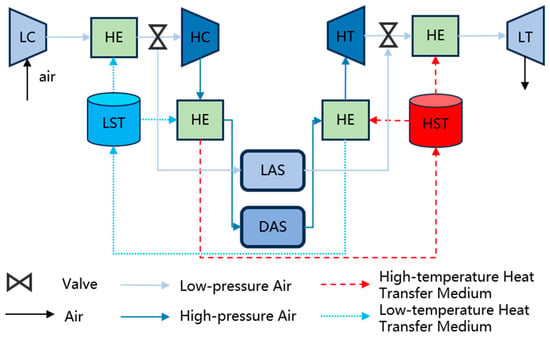
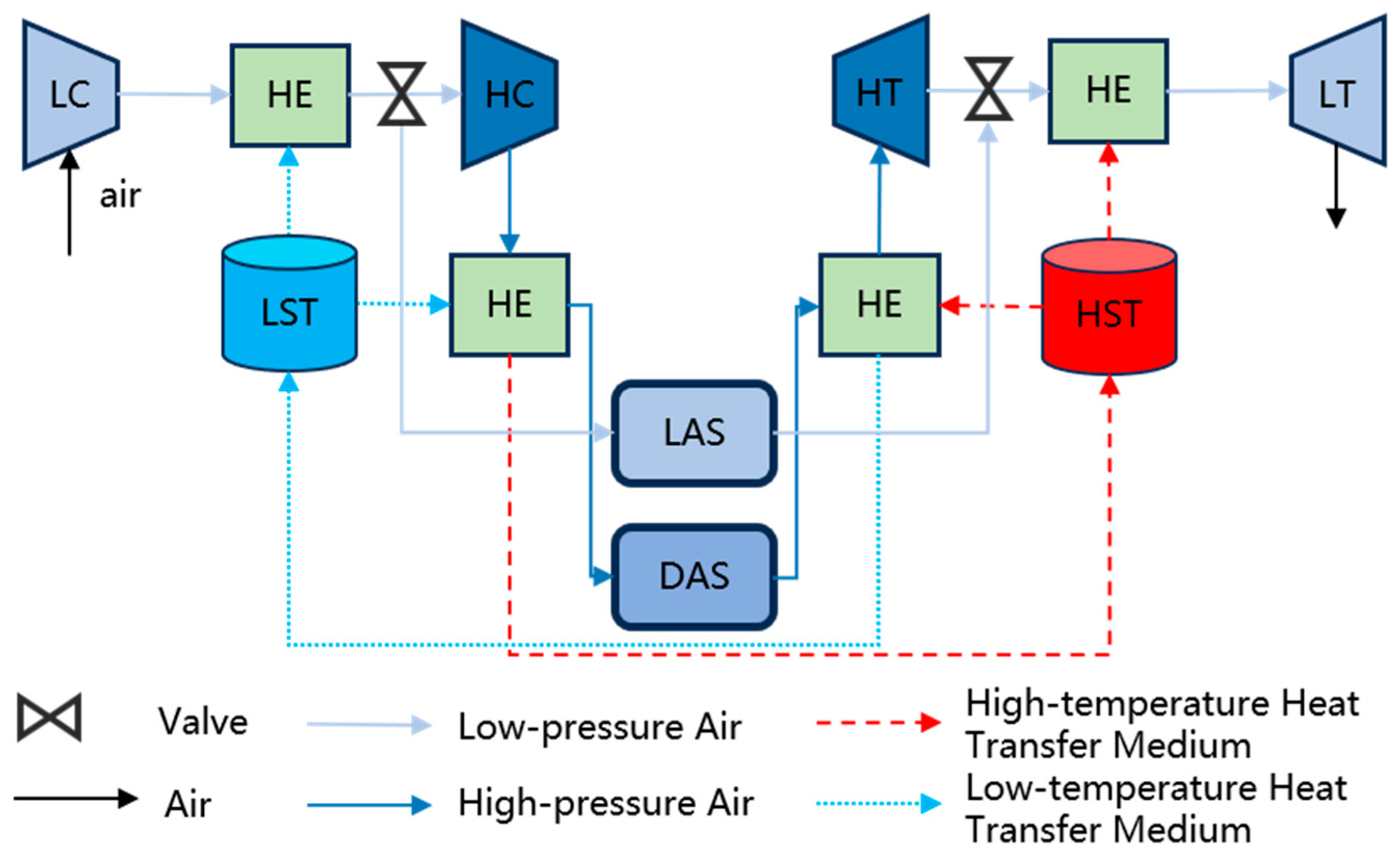
The M-UWCAES system mainly consists of two-stage compressors, two-stage turbines, inter-stage heat exchangers, two-stage storage devices, throttle valves, etc. Its structure is shown in Figure 1.
Figure 1.
Overall framework diagram of the M-UWCAES system.
This study primarily focuses on the turbine power generation subsystem, excluding the compression process. The energy release process of the M-UWCAES system comprises two modes:
- (1)
- Low-pressure Energy Release Mode (LERM): When the power demand does not exceed the rated output of the low-pressure turbine, the deep-water storage airbag exhaust valve is closed, the shallow-water storage valve is opened, only the low-pressure turbine operates. The high-pressure turbine remains inactive, the high-pressure turbine does not operate, and the inlet air temperature and pressure for the low-pressure turbine are those of the shallow-water storage airbag.
- (2)
- High-pressure Energy Release Mode (HERM): When the power demand exceeds the rated output of the low-pressure turbine, the shallow-water storage airbag exhaust valve is closed, the deep-water storage valve is opened, and both the high-pressure and low-pressure turbines are activated for energy release. The inlet air temperature and pressure for the high-pressure turbine are those of the deep-water storage airbag, while the inlet air for the low-pressure turbine is the exhaust air from the high-pressure turbine.
2.2. Thermodynamic Model of the Turbine Subsystem
2.2.1. Turbine
The turbine is a device that expands high-pressure gas to drive a generator to produce electrical power. Its actual expansion process approximates an isentropic process. The outlet pressure, outlet temperature, and output power are expressed as follows:
where l denotes the low-pressure turbine, h denotes the high-pressure turbine, pin,k is the inlet air pressure of the k stage turbine (Pa), pout,k is the outlet air pressure of the k stage turbine (Pa), Tout,k is the outlet air temperature of the k stage turbine (K), Tin,k is the inlet air temperature of the k stage turbine (K), Pout,k is the output power of the k stage turbine (W), ηs,k is the isentropic efficiency of the k stage turbine, βk is at different depths to provide the expansion ratio of the k stage turbine, γ is the specific heat ratio (typically 1.4 for air), cp is the specific heat capacity of air at constant pressure (typically 1005 J/(kg·K)), ṁair,k is the air mass flow rate through the k stage turbine (kg/s), ηc is the mechanical efficiency of the turbine, which equivalently encompasses the energy loss incurred due to mechanical friction and wear of turbine components during operation and mode switching.
The characteristic curve of the turbine is represented based on a modified Flügel formula [22]:
where is the dimensionless reduced mass flow rate through the turbine, is the dimensionless reduced rotational speed of the turbine, is the dimensionless value of the turbine inlet air temperature, is the expansion ratio of the k stage turbine, is the dimensionless value of the turbine isentropic efficiency, and the dimensionless parameter b is determined by fitting based on the actual operating characteristic curves of the turbine, and its value varies across different turbines. (typically taken as 0.3).
2.2.2. Heat Exchanger
The heat exchanger on the turbine side is primarily used for heat exchange between low-temperature air and the internal heat transfer fluid. Its heat exchange characteristics can be expressed as:
where is the heat exchanger inlet air temperature (K), is the heat exchanger outlet air temperature (K), is the air mass flow rate through the heat exchanger (kg/s), is the mass flow rate of the heat transfer fluid after heat exchange (kg/s), is the specific heat capacity of the heat transfer fluid at constant pressure (kJ/(kg·K)), is the temperature of the heat transfer fluid before entering the heat exchanger (K), and is the temperature of the heat transfer fluid after exiting the heat exchanger (K).
2.2.3. Throttle Valve
During the energy release process, the valve opening is controlled to change system operating mode and regulate the air mass flow rate exiting the airbag. Assuming the air passing through the throttle valve behaves as an ideal gas with constant specific heat, and the throttling process is adiabatic, the mass flow rate can be expressed as:
where is the outlet mass flow rate of the throttle valve (kg/s), is the fluid compressibility factor (applicable to air using the provided formula), is the valve admittance, is the throttle valve characteristic function, is the inlet air density (kg/m3), is the pressure difference across the valve (Pa), and k is the specific heat ratio.
2.2.4. Storage Device
This paper employs a flexible airbag as the storage device. It overcomes the geological constraints of traditional CAES that rely on specific salt caverns or rock caves, allowing deployment in nearshore areas, lakes, or reservoirs with sufficient water depth, significantly enhancing site selection flexibility. Moreover, by arranging airbags at different water depths, stepwise differentiation of storage pressure can be achieved. The rated operating pressure of each storage unit is determined by its deployment depth, following the hydrostatic pressure formula:
where is atmospheric pressure (Pa), is the storage depth (m), is the acceleration due to gravity (m/s2), and ρw is the density of seawater (kg/m3).
Although the underwater storage device is not perfectly adiabatic, the underwater temperature variation range is relatively small. Therefore, it is assumed that the temperature of the gas inside the storage device equals the ambient underwater temperature. The change in compressed air mass within the airbag is calculated as:
where p is the gas pressure (Pa), V is the gas volume (m3), m is the gas mass (kg), T is the thermodynamic temperature of the gas (K), Va is the initial volume of the airbag (m3), and Vb is the final volume of the airbag (m3).
3. Fuzzy PID-Based Power Tracking Control
3.1. Fuzzy PID Control Framework for the Turbine Subsystem
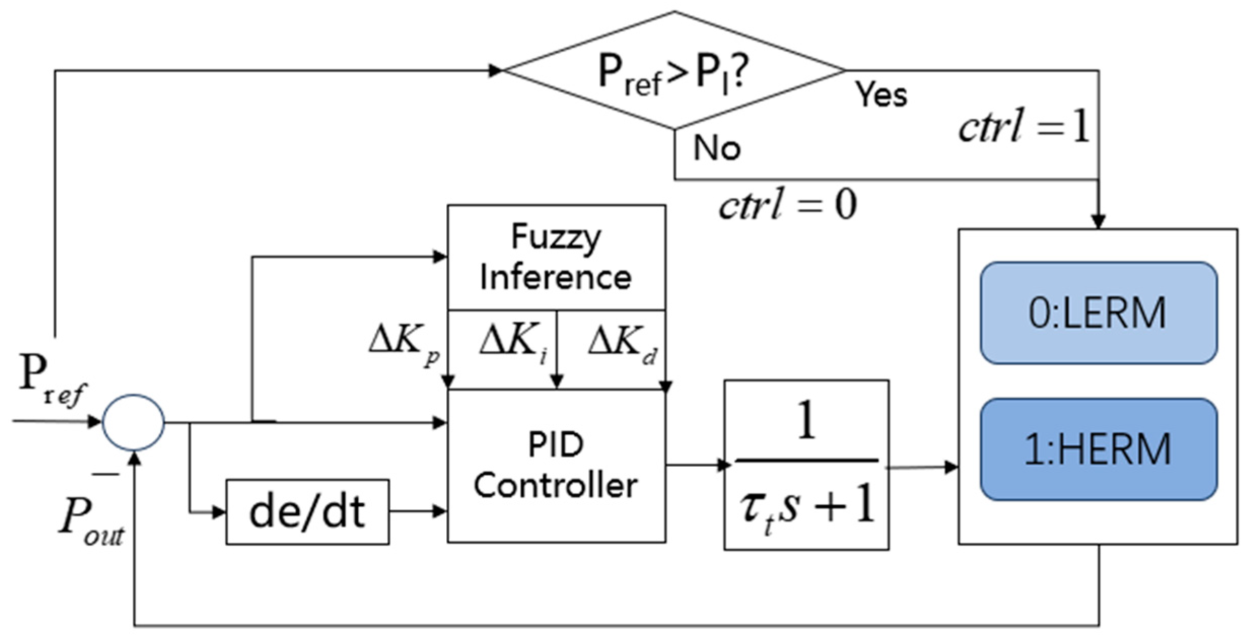
The purpose of secondary frequency regulation in the UWCAES system is to quickly and accurately track the power system’s Automatic Generation Control (AGC) commands, ensuring that the system’s power output matches grid demand in real time. However, with a multi-level storage configuration, this power tracking process becomes more complex. On one hand, parameters such as pressure and flow rate across different storage levels are interdependent, requiring precise coordinated control for optimal energy conversion and utilization. On the other hand, the multi-level configuration increases system dynamics. During system operation, switching occurs between high-pressure and low-pressure release modes. Traditional PID controllers have fixed parameters determined through tuning for a specific operating condition, lacking the ability for online parameter re-tuning; they are suitable only for single-mode operation. Therefore, considering fuzzy logic rules, a fuzzy PID controller is applied to the M-UWCAES system. The designed fuzzy PID control framework for the turbine power generation subsystem is shown in Figure 2. The system dynamic process is characterized by a first-order inertia element, where t represents the time delay coefficient of the turbine process, with a value of 0.5.
Figure 2.
Fuzzy PID Control Framework for Energy Release Process.
In the fuzzy inference stage, the adaptive fuzzy PID controller in this paper is designed based on the standard Mamdani fuzzy inference process. First, input fuzzification is performed, utilizing triangular membership functions to map crisp input variables into degrees of membership for various fuzzy sets. Next, the fuzzy operator and implication are applied; the minimum (min) operator is used to handle the logical “AND” when evaluating the rule antecedents, and the min method is similarly employed to truncate the consequent fuzzy sets based on the activation weight of the antecedents. Subsequently, aggregation is conducted, using the maximum (max) operator to combine the truncated consequents of all activated rules into a single output fuzzy set. Finally, the system employs the Centroid method for defuzzification, converting the aggregated fuzzy set into the precise control laws required by the actuator. The calculation formula for the Centroid method is as follows:
where represents the precise output variation after defuzzification (i.e., , , ); denotes the discrete sample points in the output universe of discourse; and is the membership value of the aggregated fuzzy set at the corresponding point. This mechanism ensures the smoothness and continuity of the PID control parameter adjustments.
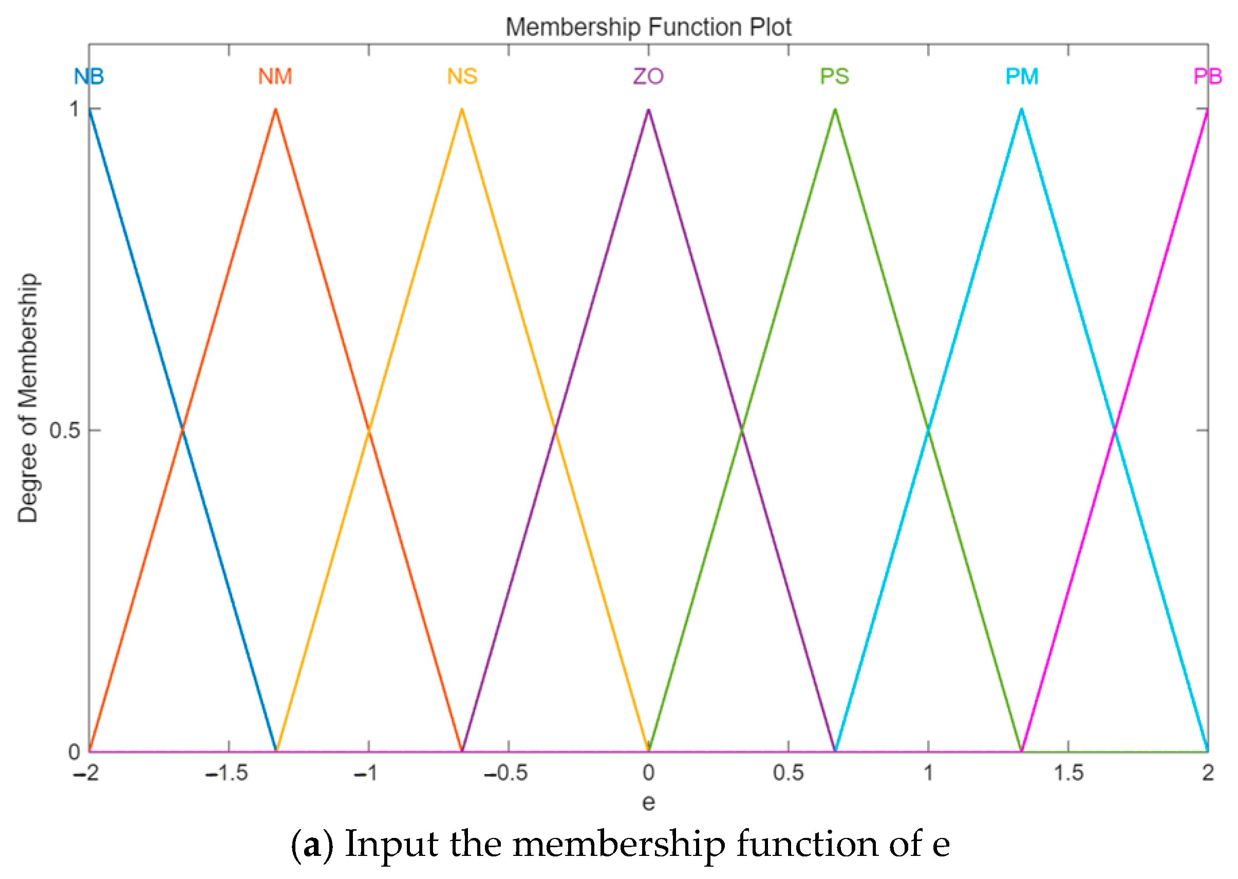
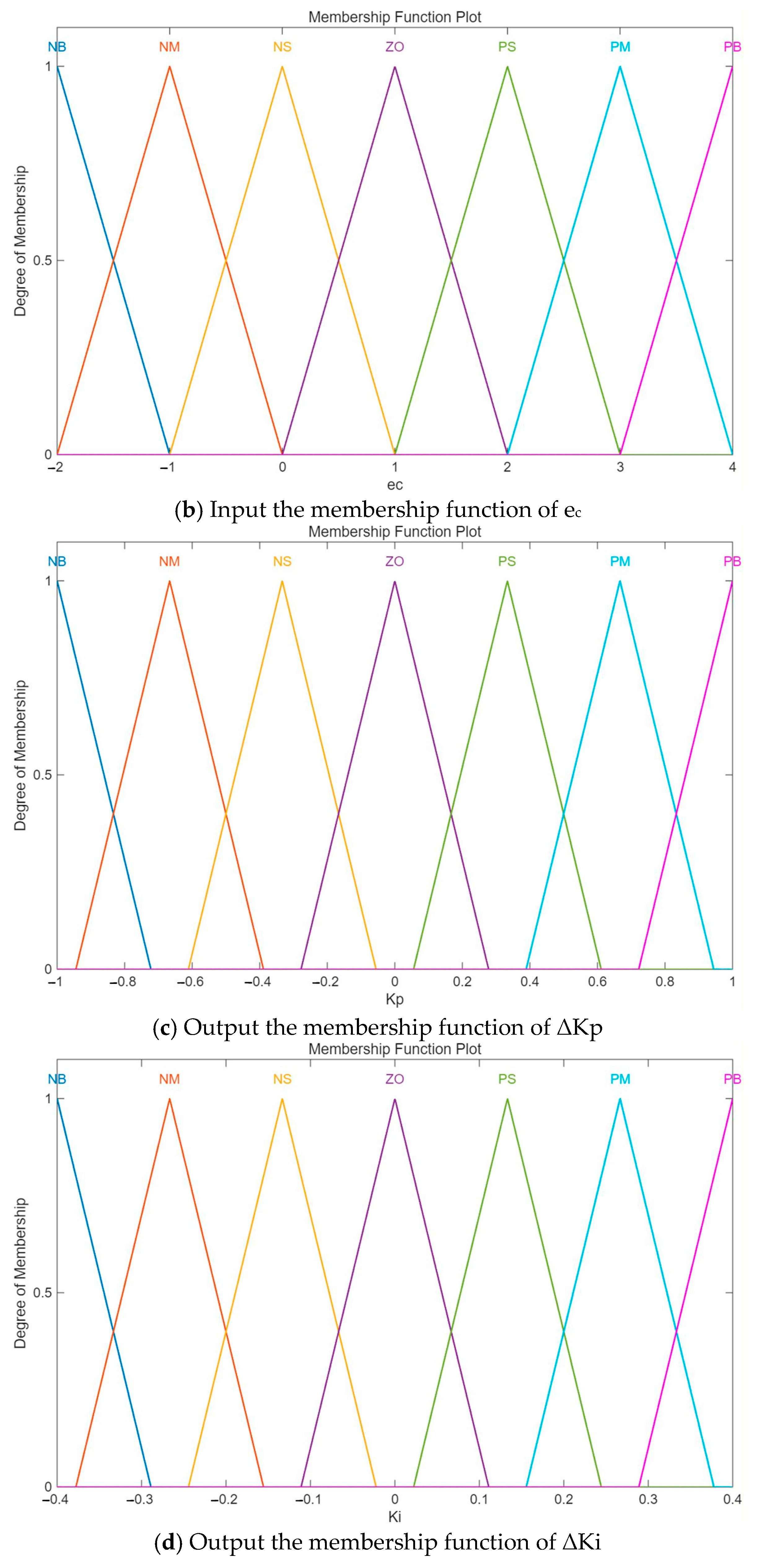
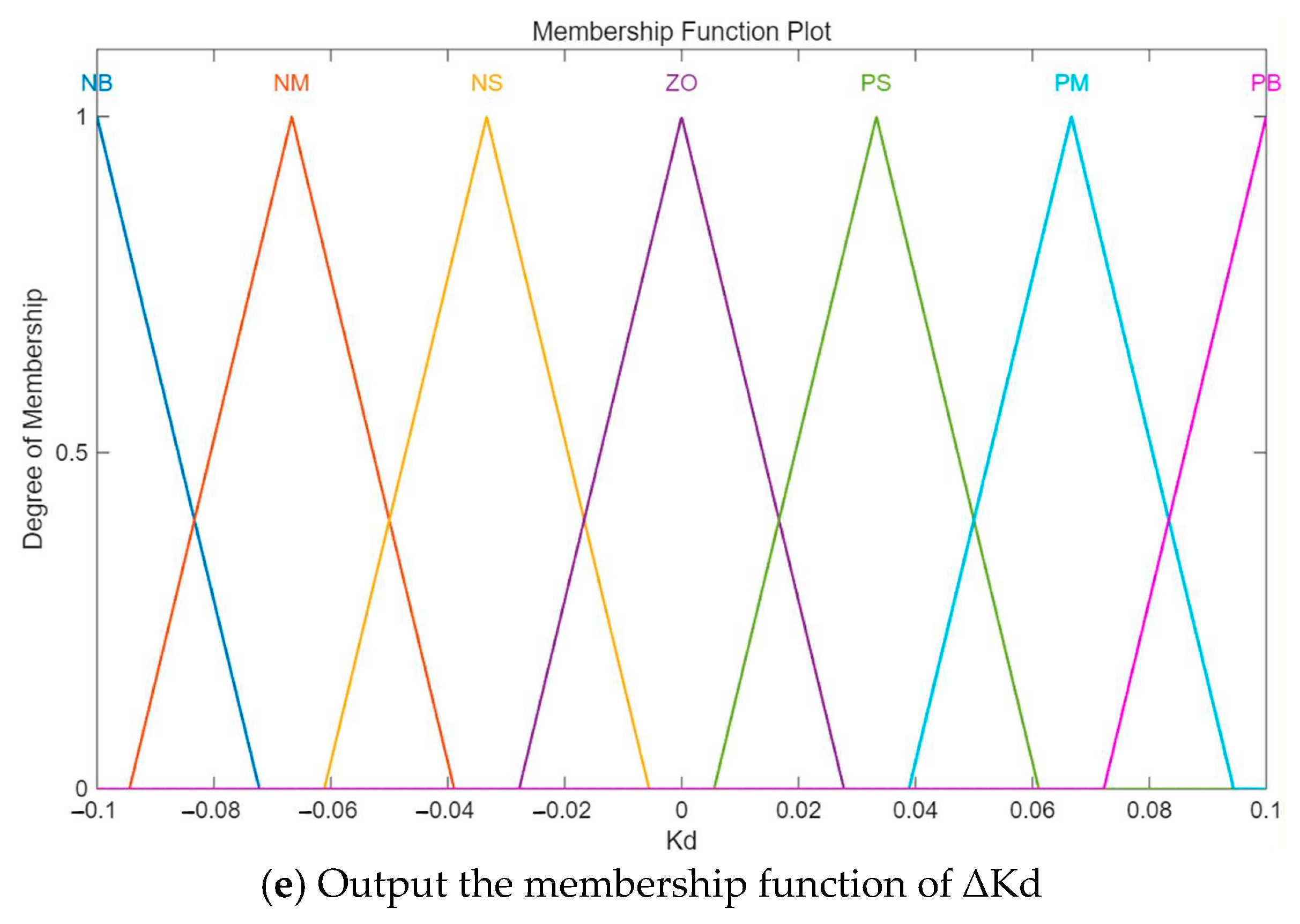
Based on the dynamic characteristics of the deviation e between the total output power of the M-UWCAES system and the power command, and its rate of change ec, fuzzy control rules (detailed in Table 1, Table 2 and Table 3) are formulated. The basic domains of the input variables are [−2, 2] and [−2, 4] respectively. Triangular functions serve as membership functions for input and output variables. Through fuzzy inference, the changes in proportional coefficient ΔKp, integral coefficient ΔKi, and derivative coefficient ΔKd of the PID controller are adjusted in real-time, achieving adaptive PID parameter tuning.
Table 1.
Fuzzy rule table for ΔKp.
Table 2.
Fuzzy rule table for ΔKi.
Table 3.
Fuzzy rule table for ΔKd.
In the rule design, the input and output variables are each divided into seven fuzzy sets: NB, NM, NS, ZO, PS, PM, PB (Negative Big, Negative Medium, Negative Small, Zero, Positive Small, Positive Medium, Positive Big), representing different magnitudes and trends of deviation. The fuzzy rule tables (Table 1, Table 2 and Table 3) are constructed according to the dynamic characteristics of the M-UWCAES turbine-side power generation process and the regulation principles of PID parameters under different power tracking error states. When the deviation is large or changing rapidly, proportional action is enhanced for faster response, while integral action is suppressed to avoid overshoot. When the deviation is small or near steady state, integral action is strengthened to eliminate steady-state error, and derivative action is appropriately adjusted to suppress oscillations. The 49 rules comprehensively cover the combinations of e and ec, enabling adaptive adjustment of PID parameters during different power command variations and operating-mode transitions [23,24,25]. The membership functions of input and output variables for fuzzy adaptive PID controller are shown in Figure A1.
For the M-UWCAES system, the switching between the HERM and LERM involves a series of physical transition processes, such as valve actuation, airflow path reconstruction, and turbine state transition. To characterize the comprehensive dynamic lag caused by these processes, an independent first-order inertia link is introduced at the mode-switching link of the control loop to equivalently model the dwell-time characteristic.
The transfer function of this first-order inertia link is expressed as:
where denotes the time-delay coefficient of mode switching, and the value is set as = 2 s.
3.2. Safe Operation Constraints
To ensure the safe and stable operation of M-UWCAES under different operating modes while achieving the intended power tracking objectives, inequality constraints on the turbine side must be considered. These include lower limits for turbine outlet air pressure, limits for turbine inlet temperature, upper and lower bounds for heat transfer oil mass flow rate, constraints for air mass flow rate range, and constraints on the air-side temperature difference across heat exchangers. The turbine outlet pressure should not fall below the shallow-water storage pressure, and the low-pressure turbine outlet pressure must be at least equal to the ambient pressure to prevent backflow due to negative pressure differentials. The inlet and outlet gas temperatures must be above the minimum permissible value and not exceed material high-temperature limits. The flow rates of gas and heat transfer fluid must also remain within permissible limits.
where is the dew point temperature corresponding to the gas pressure, and is the high-temperature material limit for turbine blades. Subscripts min and max denote the lower and upper bounds of the respective variables.
4. Case Study Simulation
4.1. Case Description
To comprehensively evaluate the effectiveness and adaptability of the proposed control strategy, a dynamic simulation model of the turbine side of the M-UWCAES system is developed. The main simulation parameters are listed in Table 4. Key parameters such as turbine isentropic efficiency and heat exchanger effectiveness are set based on reference [26]. To verify the comprehensive performance of the proposed control strategy, the performance advantages of M-UWCAES over UWCAES during power tracking are first compared. Subsequently, the power tracking capability of the proposed control strategy is compared with that of traditional PID control for the M-UWCAES system.
Table 4.
Simulation parameter settings.
4.2. Analysis of Power Tracking Response Characteristics
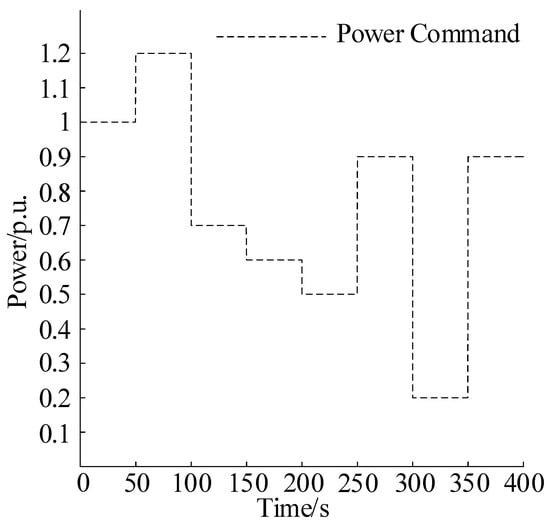
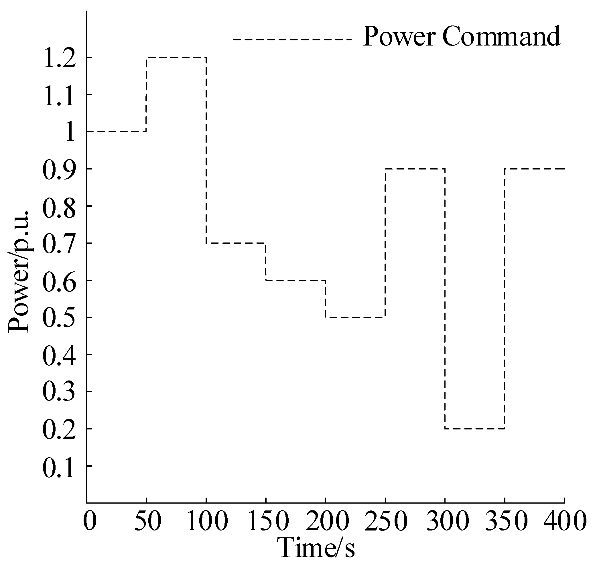
To test the performance of the M-UWCAES system under time-varying power commands Pref, a simulation scenario with multiple step changes is designed. The system initially operates at 1 p.u. power. Step changes of +0.2 p.u., −0.5 p.u., −0.1 p.u., −0.1 p.u., +0.4 p.u., −0.6 p.u., and −0.7 p.u. are applied at T = 50 s, 100 s, 150 s, 200 s, 250 s, 300 s, and 350 s, respectively, as shown in Figure 3. This scenario simulates grid power regulation demands. The comparative analysis between the M-UWCAES and conventional UWCAES effectively tests the system’s tracking capability.
Figure 3.
Power Command.
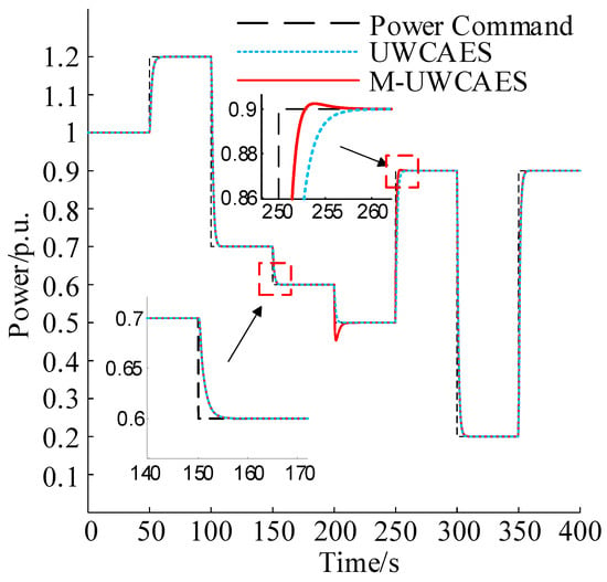
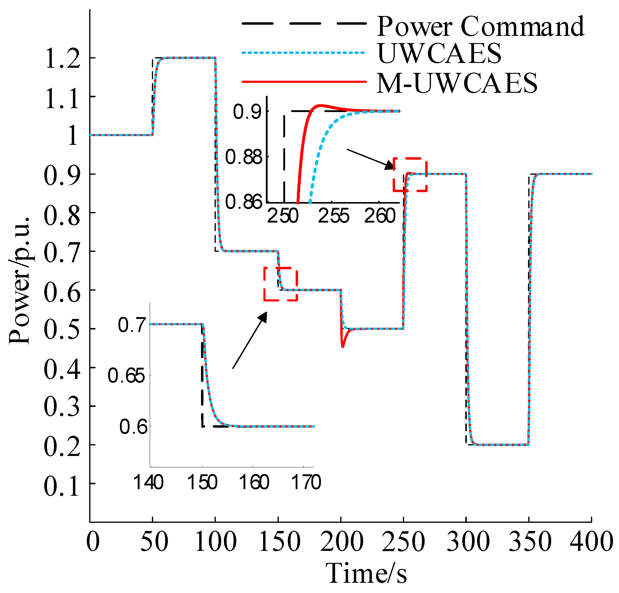
Simulation results shown in Figure 4 indicate that, under the same power command scenario, when the M-UWCAES system switches between high-pressure and low-pressure release modes (due to the shutdown of the high-pressure turbine, with output power fully transferring to the low-pressure turbine), a brief power overshoot occurs, followed by rapid stabilization. When Pref > Pl, the power tracking response speeds are identical. When Pref <Pl, because the PID controller parameters are tuned based on the high-pressure release mode, there is a slight parameter mismatch for low-pressure release mode operation, resulting in a marginally slower tracking speed compared to UWCAES, but the maximum time difference does not exceed 1 s, indicating that the introduction of the multi-level structure does not cause a significant lag in power tracking performance.
Figure 4.
Power tracking performance of UWCAES and M-UWCAES.
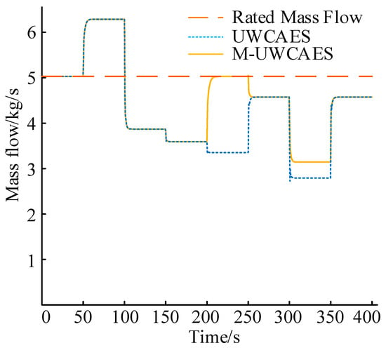
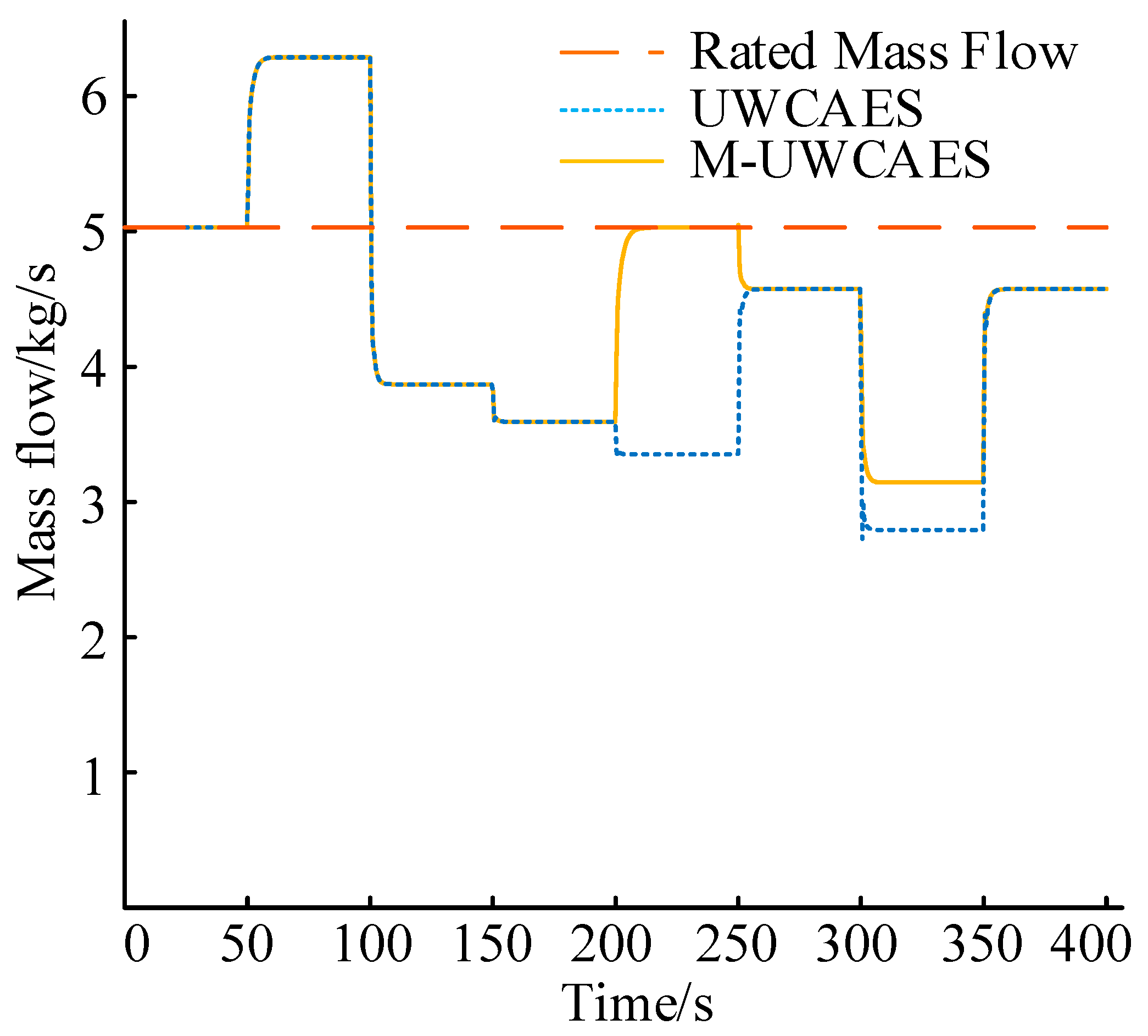
The isentropic efficiency values of low-pressure turbines under different power commands for the two systems are as shown in Table 5. Comparing operational parameters during power tracking reveals that when the power command falls below the M-UWCAES mode switching threshold, the conventional UWCAES system exhibits significant maladaptation. Since the system consistently maintains two-stage turbine series operation with equal power distribution, each stage turbine outputs low power. The resulting low air mass flow rate causes the turbines to deviate significantly from their rated operating points. In contrast, the M-UWCAES system switches to low-pressure release mode, halting the high-pressure turbine, and the power demand is placed solely on the low-pressure turbine. The variation in air mass flow rate is smaller, the turbine deviates less from its rated condition, as shown in Figure 5.
Table 5.
Isentropic efficiency of low-pressure turbines.
Figure 5.
System air mass flow of different gas storage structures.
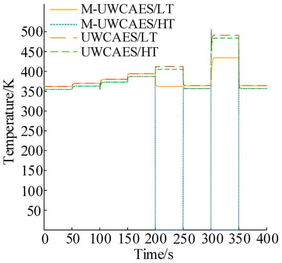
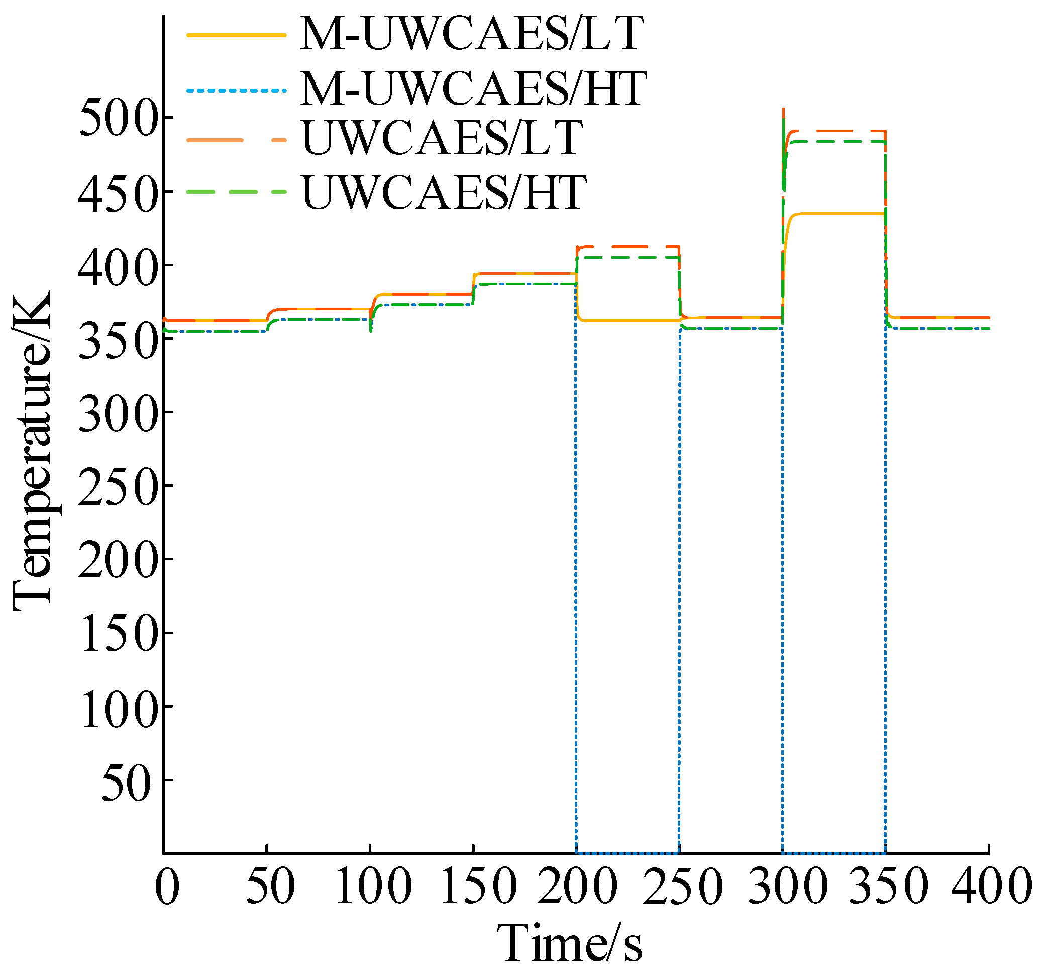
Further comparison of turbine outlet temperatures shows that, for the same heat exchanger outlet temperature, the M-UWCAES system in low-pressure release mode has a relatively lower low-pressure turbine outlet temperature, as shown in Figure 6. For Pref = 0.5 p.u., = 361.8 K, while = 412.4 K. For Pref = 0.2 p.u., = 434.6 K, while = 491.2 K.
Figure 6.
Turbine outlet temperature for systems with different storage structures.
The lower outlet temperature indicates that during the M-UWCAES energy release process, more thermal energy is converted into mechanical work during turbine expansion rather than being discharged as residual heat. To facilitate performance comparison under different operational control strategies, the exergy efficiency of the power generation process is defined as the ratio of the system output power to the sum of the exergy of the compressed gas in the storage bag and the thermal exergy of the heating fluid in the thermal storage tank [27]. Its calculation formula is as follows:
where is the physical exergy power of compressed air, W; is the thermal exergy power of heat transfer oil, W; is the total turbine-side power generation power, W.
The efficiencies at various power commands are shown in Table 6. In high-pressure release mode, M-UWCAES and UWCAES exhibit identical exergy efficiencies. However, in low-pressure release mode, M-UWCAES demonstrates a significant advantage: at Pref = 0.5 p.u., exergy efficiency increases by 4.69%; at Pref = 0.2 p.u., the increase is 13.75%. This indicates that the multi-level storage configuration enhances energy utilization efficiency by optimizing the operational mode.
Table 6.
Exergy Efficiency of the System Power Generation Process.
4.3. Fuzzy PID Control Performance Analysis
To verify the superiority of fuzzy PID control in the M-UWCAES system, this section conducts a comparative analysis of the dynamic response performance of the proposed fuzzy PID controller, PID controller, and sliding mode control (SMC) under the same power command.
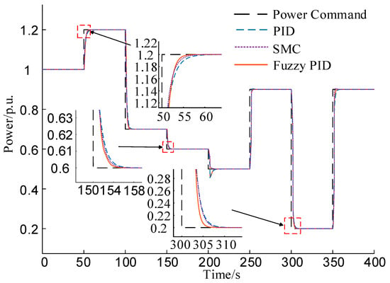
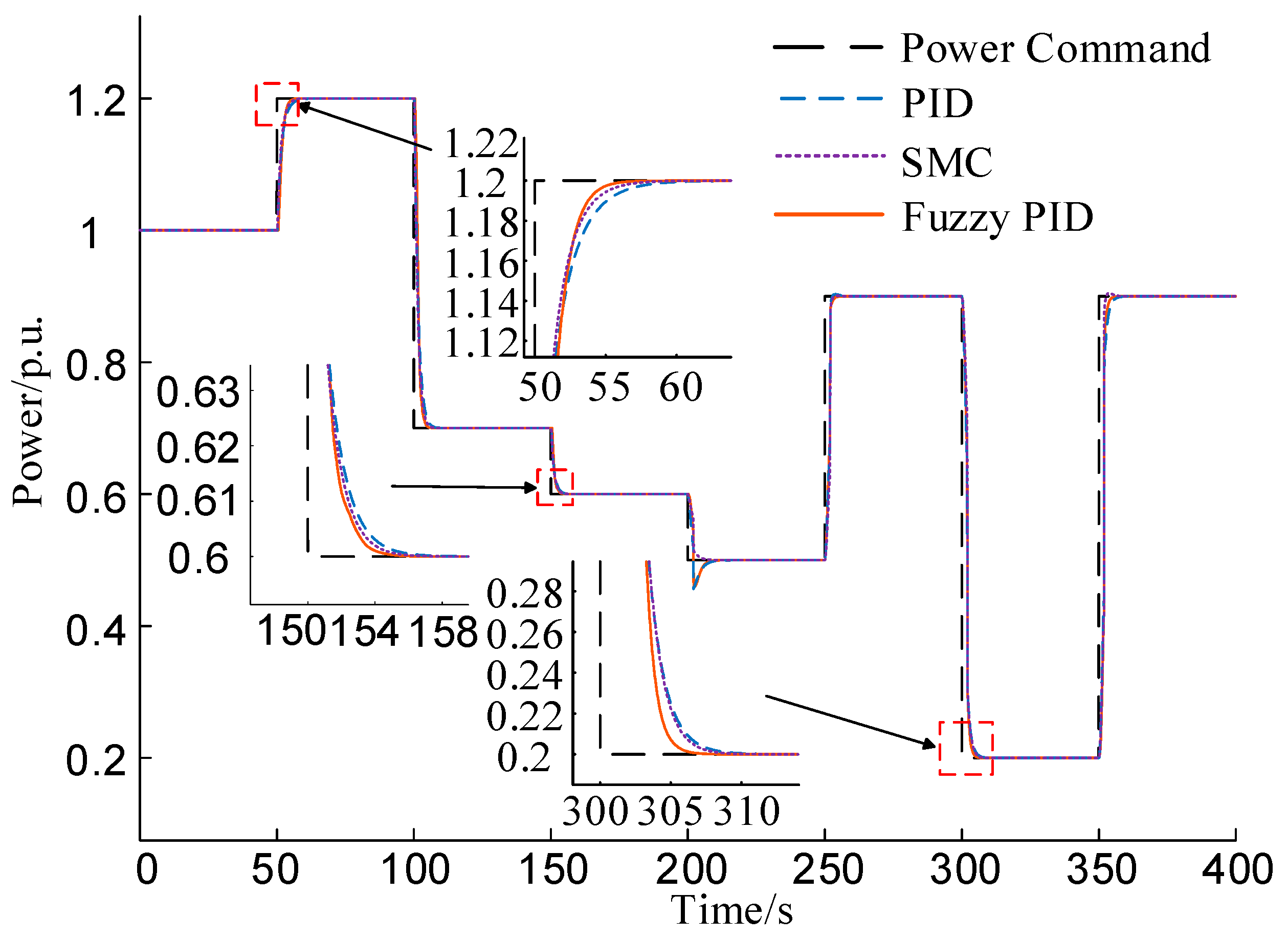
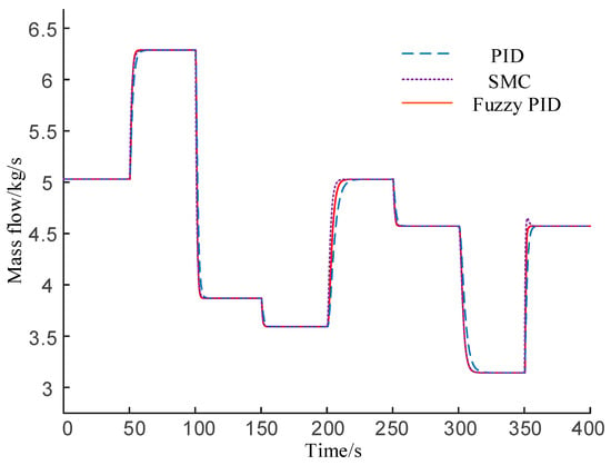
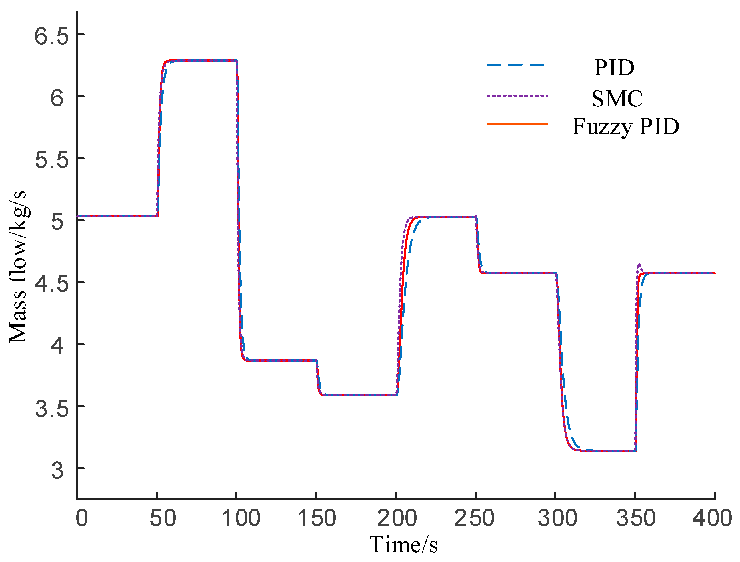
Figure 7 compares the dynamic tracking performance of PID, sliding mode control and the proposed adaptive fuzzy PID controller under multiple step power commands across a wide load range. For the step-up transient at t = 50 s when the power command rises from 1.0 p.u. to 1.2 p.u., the fuzzy PID achieves a settling time of 9.5 s, outperforming PID at 14.5 s and SMC at 12 s with smaller overshoot. It also delivers faster convergence and negligible overshoot during step-down transients across all load levels, and effectively attenuates mode-switching oscillation with lower steady-state error. This performance is consistent with the MAPE results and verifies the superior overall regulation capability of the proposed strategy for the M-UWCAES system. Furthermore, the dynamic response comparison of the mass flow rate shown in Figure 8 also confirms the overall advantages of the proposed adaptive fuzzy PID controller in both transient performance and steady-state accuracy.
Figure 7.
Comparison chart of SMC, Fuzzy PID and PID control effects.
Figure 8.
Airflow variation charts under different control strategies.
These results demonstrate that the fuzzy PID-based power tracking control strategy improves the dynamic tracking performance, reduces overshoot during mode transitions, and provides adaptive regulation capability under the investigated operating conditions.
To further illustrate the advantages of fuzzy PID, the gap between the actual power and the power command of each system is measured using mean absolute percentage error (MAPE). The calculation method is as follows:
The comparison results of power tracking MAPE among different control strategies are shown in the Table 7.
Table 7.
Comparison of power tracking MAPE among different control strategies.
As shown in Table 7, the MAPE is used to measure how accurately different control strategies can track steady-state power. The results show that the Fuzzy PID controller comes out on top with the lowest MAPE of 0.02708. In comparison, the traditional PID controller and SMC have MAPE values of 0.02721 and 0.02712, respectively. This means the Fuzzy PID reduces tracking error by 0.00012 and 0.00003, respectively, which proves that its adaptive parameter tuning can more precisely keep the actual output power in line with the dynamic reference, giving it better tracking accuracy and stability than the conventional methods.
Beyond the dynamic and thermodynamic performance advantages discussed above, the proposed M-UWCAES system also presents a favorable qualitative cost-benefit profile. It is undeniable that integrating an additional flexible storage airbag deployed in the shallow-water region into the conventional UWCAES architecture increases the initial capital expenditure and physical system complexity. However, the simulation results indicate that this specific structural addition is highly economically justified during the operational phase. In the secondary frequency regulation application scenario, the system frequently operates under partial-load conditions. Utilizing the added shallow-water airbag enables a dedicated low-pressure energy release mode, which successfully prevents the turbines from operating under severe off-design conditions. This structural flexibility improves the partial-load exergy efficiency by 4.69–13.75%, which directly translates to reduced compressed air consumption and lowers the long-term operational expenditures. Furthermore, the exceptional tracking accuracy (a MAPE of 0.01648) and rapid dynamic response achieved by the adaptive fuzzy PID controller are highly valued in grid ancillary service markets. Consequently, the minor initial hardware investment for the shallow-water airbag is effectively offset by the sustained operational savings and the enhanced financial compensation derived from the system’s superior AGC tracking performance.
5. Discussion
This study proposed an adaptive fuzzy PID-based turbine-side power tracking strategy for an M-UWCAES system. A dynamic model of the turbine-side energy release process was established, and the effectiveness of the proposed strategy was verified through comparative simulations.
The results show that the multi-level storage configuration improves the operating flexibility of UWCAES by enabling automatic switching between low-pressure and high-pressure energy release modes. Under partial-load conditions, M-UWCAES reduces turbine off-design deviation and improves the exergy efficiency of the power generation process by 4.69–13.75% compared with conventional UWCAES.
The proposed adaptive fuzzy PID controller further enhances the dynamic tracking performance of the M-UWCAES system. By tuning PID parameters online according to the power tracking error and its variation, the controller achieves faster response, smaller overshoot during mode switching, and lower tracking error than traditional PID and sliding mode control. In the representative step response, the settling time is reduced to approximately 10 s, and the MAPE decreases to 0.02709.
Overall, the proposed multi-level storage structure and adaptive fuzzy PID control strategy provide an effective approach for improving the operational flexibility and power regulation capability of UWCAES systems under fluctuating offshore renewable power conditions. Future work will focus on experimental validation, more detailed modeling of practical losses and actuator constraints, and coordinated optimization of storage depth, capacity allocation, and mode-switching thresholds.
Author Contributions
Conceptualization, Y.X.; methodology, Y.Z. (Yangyang Zeng); software, X.G.; validation, G.L.; formal analysis, Y.Y.; investigation, Z.H.; resources, R.L.; data curation, Y.Z. (Yongjie Zhang); writing—original draft preparation, Y.Z. (Yongjie Zhang); writing—review and editing, R.L.; visualization, X.G.; supervision, Y.Z. (Yangyang Zeng); project administration, G.L.; funding acquisition, Y.X. All authors have read and agreed to the published version of the manuscript.
Funding
This research was funded by the Science and Technology Project of China Southern Power Grid Co., Ltd., grant number 035200KC25040001; and the Joint Funds of the National Natural Science Foundation of China, grant number U25B6024.
Data Availability Statement
The original contributions presented in this study are included in the article. Further inquiries can be directed to the corresponding author.
Conflicts of Interest
The authors, Yongjie Zhang, Rong Li, Yangyang Zeng, Xingyuan Guo, Guiguo Lin and Yu Xiao, were employed by the company Jieyang Power Supply Bureau, Guangdong Power Grid Co., Ltd. And Yi Yang and Zheng Huang were employed by the Guangdong National Research Institute of New Energy Storage Co., Ltd. The remaining authors declare that the research was conducted in the absence of any commercial or financial relationships that could be construed as a potential conflict of interest. The authors declare that this study received funding from the Science and Technology Project of China Southern Power Grid Co., Ltd. The funder was not involved in the study design, collection, analysis, interpretation of data, the writing of this article or the decision to submit it for publication.
Abbreviations
The following abbreviations are used in this manuscript:
| M-UWCAES | Multi-level Underwater Compressed Air Energy Storage |
| UWCAES | Underwater Compressed Air Energy Storage |
| LC | Low-pressure Compressor |
| HC | High-pressure Compressor |
| HE | Heat Exchanger |
| LST | Low-temperature Storage Tank |
| HST | High-temperature Storage Tank |
| LAS | Shallow-water Air Storage |
| DAS | Deep-water Air Storage |
| HT | High-pressure Turbine |
| LT | Low-pressure Turbine |
| LERM | Low-pressure Energy Release Mode |
| HERM | High-pressure Energy Release Mode |
Appendix A
The fuzzy adaptive PID controller can be divided into zero state, positive state, and negative state according to the state of the actual variable, and uses seven levels: negative large, negative medium, negative small, zero, positive small, positive medium, and positive large to distinguish the specific state when the input and output variables are positive or negative. Its domain is divided into seven levels [NB, NM, NS, ZO, PS, PM, PB], and the membership function is shown in Figure A1.
Figure A1.
Membership functions of input and output variables for fuzzy adaptive PID controller.
References
- National Energy Administration. Grid-Connected Operation Status of Renewable Energy in 2024. Available online: https://www.nea.gov.cn/20250221/e10f363cabe3458aaf78ba4558970054/c.html (accessed on 27 January 2025).
- Zhou, W.B.; Huang, W. Voltage Control Method for Common Connection Points of Offshore Wind Farms Based on Cloud-Edge Collaborative Architecture. J. Electr. Eng. 2023, 18, 169–180. [Google Scholar]
- Liu, M.Y.; Zhu, Y.; Cao, C.Z.; Cao, X.; Zhu, L.J.; Zheng, J.T. Research on the Performance Analysis of Compressed Air Energy Storage Systems. New Technol. Electr. Eng. Electr. Energy 2019, 38, 67–72. [Google Scholar]
- Chen, L.M.; Mei, S.W.; Wang, B.; Liu, H.; Zou, W.; Zheng, T.; Chen, R. An overview and outlook on thermal power unit coupled with compressed air energy storage. Proc. CSEE 2024, 44, 7264–7276. [Google Scholar]
- Zhang, Y.; Yin, S.Z.; Su, C.Q.; Liu, Z. Study of the underwater air energy storage with various heat storage medium and stage number. Renew. Energy 2025, 242, 122465. [Google Scholar] [CrossRef] [Scilit]
- Wang, X.; Shair, J.; Xie, X.R. Review and prospect of underwater energy storage technology. Power Syst. Technol. 2023, 47, 4121–4131. [Google Scholar]
- Liu, C.C.; Su, X.; Yin, Z.; Sheng, Y.; Zhou, X.; Xu, Y.; Wang, X.; Chen, H. Experimental study on the feasibility of isobaric compressed air energy storage as wind power side energy storage. Appl. Energy 2024, 364, 123129. [Google Scholar] [CrossRef] [Scilit]
- Bu, X.B.; Huang, S.H.; Liu, S.; Yang, Y.; Shu, J.; Tan, X.; Chen, H.; Wang, G. Efficient utilization of abandoned mines for isobaric compressed air energy storage. Energy 2024, 311, 133392. [Google Scholar] [CrossRef] [Scilit]
- Chen, L.J.; Liu, H.C.; Wang, Z.C.; Cui, S.; Mei, S.W. Research Progress and Prospects of Underwater Compressed Air Energy Storage. New Tech. Electr. Eng. Electr. Power 2025, 44, 26–39. [Google Scholar]
- Bu, X.B.; Chen, X.; Li, H.S.; Liu, S.; Shu, J. Performance analysis and efficiency improvement technology of underwater compressed air energy storage for offshore wind power. Electr. Power Constr. 2024, 45, 106–117. [Google Scholar]
- Carriveau, R.; Ebrahimi, M.; Ting, D.S.K.; McGillis, A. Transient thermodynamic modeling of an underwater compressed air energy storage plant: Conventional versus advanced exergy analysis. Sustain. Energy Technol. Assess. 2019, 31, 146–154. [Google Scholar] [CrossRef] [Scilit]
- Wang, Z.W.; Xiong, W.; Ting, D.S.K.; Carriveau, R.; Wang, Z. Conventional and advanced exergy analyses of an underwater compressed air energy storage system. Appl. Energy 2016, 180, 810–822. [Google Scholar] [CrossRef] [Scilit]
- Wang, Z.W.; Xiong, W.; Carriveau, R.; Ting, D.S.K.; Wang, Z. Energy, exergy, and sensitivity analyses of underwater compressed air energy storage in an island energy system. Int. J. Energy Res. 2019, 43, 2241–2260. [Google Scholar] [CrossRef] [Scilit]
- Szablowski, L.; Morozyuk, T. Advanced exergy analysis of adiabatic underwater compressed air energy storage system. Entropy 2023, 25, 77. [Google Scholar]
- Cheung, B.C.; Carriveau, R.; Ting, D.S.K. Multi-objective optimization of an underwater compressed air energy storage system using genetic algorithm. Energy 2014, 74, 396–404. [Google Scholar] [CrossRef] [Scilit]
- Zhao, P.; Gou, F.; Xu, W.; Wang, J.; Dai, Y. Multi-objective optimization of a renewable power supply system with underwater compressed air energy storage for seawater reverse osmosis under two different operation schemes. Renew. Energy 2022, 181, 71–90. [Google Scholar] [CrossRef] [Scilit]
- Li, M.J.; Liu, Z.B.; He, Y.L.; Zhu, S.R. Energy conversion characteristics of underwater compressed air energy storage system considering offshore wind energy fluctuation. J. Xi’an Jiaotong Univ. 2025, 59, 1–12. [Google Scholar] [CrossRef] [Scilit]
- Wang, Z.W.; Ting, D.S.K.; Carriveau, R.; Xiong, W.; Wang, Z. Design and thermodynamic analysis of a multi-level underwater compressed air energy storage system. J. Energy Storage 2016, 5, 203–211. [Google Scholar] [CrossRef] [Scilit]
- Wang, Z.C.; Liu, H.C.; Li, J.L.; Cui, S.; Chen, L.J. Configuration strategy of underwater compressed air energy storage considering multi-level gas storage arrangement. Distrib. Energy 2025, 10, 13–24. [Google Scholar]
- Precup, R.-E.; Hellendoorn, H. A survey on industrial applications of fuzzy control. Comput. Ind. 2011, 62, 213–226. [Google Scholar] [CrossRef] [Scilit]
- Khosravi, N.; Çelik, D.; Bevrani, H.; Echalih, S. Microgrid stability: A comprehensive review of challenges, trends, and emerging solutions. Int. J. Electr. Power Energy Syst. 2025, 170, 110829. [Google Scholar] [CrossRef] [Scilit]
- Zhou, A.C.; Liu, H.C.; Li, J.L.; Cui, S.; Chen, L.J. Variable step power tracking control strategy for distributed compressed air energy storage expansion power generation system. Power Gener. Technol. 2025, in press. [Google Scholar] [CrossRef] [Scilit]
- Zhu, Z.C.; Cui, S.; Chen, L.; Che, S.Y.; Mei, S.W. Primary frequency regulation control strategy for advanced adiabatic compressed air energy storage based on improved fuzzy adaptation. Power Syst. Technol. 2025, 49, 5137–5146. [Google Scholar]
- Liu, J.K. Advanced PID Control with MATLAB Simulation, 5th ed.; Publishing House of Electronics Industry: Beijing, China, 2023. [Google Scholar]
- Tian, Y.T.; Zhao, K.; Liu, W.; Sun, X.W.; Wei, W.; Mei, S.W. Coordinated fuzzy control of hybrid energy storage systems for enhanced secondary frequency regulation in power grids. J. Energy Storage 2026, 141, 119270. [Google Scholar] [CrossRef] [Scilit]
- Bai, J.Y.; Wei, W.; Chen, L.J.; Mei, S.W. Modeling and dispatch of advanced adiabatic compressed air energy storage under wide operating range in distribution systems with renewable generation. Energy 2020, 206, 118051. [Google Scholar] [CrossRef] [Scilit]
- Ma, X.; Li, K.; Zhang, C.H.; Sun, Y.X. Optimal Operation Control of Multi-stage Compressed Air Energy Storage System Under Off-design Conditions. Control Theory Appl. 2019, 36, 436–442. [Google Scholar]

Disclaimer/Publisher’s Note: The statements, opinions and data contained in all publications are solely those of the individual author(s) and contributor(s) and not of MDPI and/or the editor(s). MDPI and/or the editor(s) disclaim responsibility for any injury to people or property resulting from any ideas, methods, instructions or products referred to in the content. |
© 2026 by the authors. Licensee MDPI, Basel, Switzerland. This article is an open access article distributed under the terms and conditions of the Creative Commons Attribution (CC BY) license.