


Abstract
Online parameter estimation is essential for improving the control performance, efficiency, and reliability of permanent magnet synchronous machine (PMSM) drives. Numerous parameter estimation methods have been proposed for both position sensor-based and sensorless control. This paper presents a comprehensive review of recent developments in online parameter estimation for both three-phase and multi-phase PMSMs. Conventional methods for addressing the rank-deficiency issue, including partially fixed parameters, additional measurements, harmonic extraction, signal injection, and variable-speed excitation, are first summarized. Subsequently, the challenges of parameter estimation under sensorless control are discussed, followed by a review of virtual back-EMF, virtual extended-EMF, virtual flux linkage, and virtual active flux injection methods. Finally, recent advances in dual three-phase PMSMs are reviewed by exploiting the additional degrees of freedom provided by multi-phase machines. The advantages, limitations, and future research directions of representative parameter estimation methods are also discussed.
1. Introduction
Permanent magnet synchronous motors (PMSMs) have been widely used in electric vehicles, renewable energy systems, industrial automation, aerospace, and robotics due to their high power density, high efficiency, and excellent dynamic performance [1,2,3,4,5,6,7]. However, the machine parameters, including the stator resistance, dq-axis inductances, and permanent magnet (PM) flux linkage vary significantly with operating conditions such as temperature, magnetic saturation, and device aging [8,9,10,11,12,13]. These parameter variations may deteriorate the performance of current control, torque control, sensorless control, and predictive control. Therefore, accurate online parameter estimation has become an important technique for improving the performance and reliability of PMSM drive systems [14,15,16,17,18,19].
For online parameter estimation of PMSMs based on rotor position-sensored drives, the key issue is to solve the rank-deficiency, i.e., the number of parameters to be estimated is greater than the number of machine equations [20,21,22,23]. There are five unknown parameters, namely winding resistance, dq-axis inductances, PM flux linkage, and inverter nonlinearity voltage error, but with only two independent dq-axis voltage equations. Different methods [24,25,26,27,28,29,30,31,32,33,34,35,36,37,38,39,40,41,42,43,44,45,46,47,48,49,50,51,52,53,54,55,56,57,58,59,60] have been proposed to solve the rank-deficiency issue, including partially fixed parameter [24,25,26,27], additional measuring instruments [28,29,30], harmonic extraction [31,32,33,34,35,36], and signal injection [37,38,39,40,41,42,43,44,45,46,47,48,49,50,51,52,53,54,55,56,57,58], which cannot be applied to sensorless control directly [59,60].
In conventional fundamental model-based sensorless control methods, the rotor position is obtained by observing either the back-EMF [61,62,63,64,65,66,67] or the flux linkage [68,69,70,71,72,73,74] derived from the machine fundamental model. Nevertheless, the estimation accuracy is strongly influenced by parameter variations and inverter nonlinear effects, resulting in rotor position deviations that adversely affect full-parameter estimation. Therefore, the difficulty of parameter estimation lies in the fact that the number of equations of the fundamental model is fixed, but the parameter identification under sensorless control has an additional unknown parameter, i.e., rotor position error.
For parameter estimation under sensorless control for high-speed PMSMs, a discrete model with high accuracy and efficient calculation is developed in [75] for accurate stator resistance and inductance estimations. However, even with simplification, the discrete model is still complex, coupled, and nonlinear. To obtain accurate inductances of high-speed PMSM, the current injection is employed to construct a simplified yet precise inductance estimation model, where the rotor position estimation error is eliminated [76]. Further, to avoid the degradation of the robustness and acoustic performance by the current injection method, the non-injection method, i.e., PWM current ripple, is introduced to identify the rotor position estimation error for compensation and successfully applied to PMSM without [50]/with [77] saliency. In [78], an analytical function is introduced based on the relationship between position estimation error and parameter mismatches for multi-parameter estimation in an Interior PMSM (IPMSM). Based on the nonlinear dq-axis inductance estimation method in [79], an adaptive robust observer for synchronous machines is further proposed in [80] to mitigate position estimation errors due to parameter mismatches.
Based on the above analysis, for sensorless control, the key challenge of online parameter identification is that the unknown rotor position error, Δ, will be changed after current injection [47,81,82,83,84,85,86,87,88,89,90,91] and position-offset injection [92,93,94,95]. As a result, the rotor position error, Δ, has to be included as an additional estimation variable. While the injected signals provide extra equations, they also introduce an additional unknown, making the overall estimation problem more challenging. By virtual signal injection, i.e., virtual back-EMF/virtual flux linkage injection, the independent equations will be increased, but the number of unknown parameters will not be increased since during virtual signal injection [96,97,98,99,100,101,102], the estimated rotor position is immune to parameter mismatches and inverter nonlinear effects, effectively removing the influence of position estimation errors on the parameter identification process. At the same time, the emerging trends in online parameter estimation using digital twins and data-driven methods are introduced as well [103,104,105,106,107,108].
Online parameter estimation techniques have also been increasingly extended beyond conventional drive control to thermal condition monitoring and health management of electrical machines. By exploiting the temperature dependence of electrical parameters, recent studies have developed real-time thermal monitoring methods, including online hot-spot winding temperature prediction based on stator resistance estimation, maximum permanent magnet temperature prediction based on flux linkage estimation, thermal parameter identification using high-fidelity lumped-parameter thermal models, and maximum winding temperature prediction for electrically excited synchronous machines. These studies demonstrate that online parameter estimation can not only improve drive performance but also provide an effective foundation for predictive maintenance and reliability enhancement [109,110,111,112].
Compared with conventional three-phase machines, multi-phase PMSMs provide additional control degrees of freedom through extra winding sets and harmonic subspaces. These characteristics enable more flexible excitation and facilitate the decoupling of different machine parameters, making multi-phase drives particularly attractive for high-performance parameter estimation, fault-tolerant operation, and safety-critical applications [113,114,115,116,117,118,119,120,121,122,123,124,125,126,127,128]. Consequently, online parameter estimation techniques developed for three-phase PMSMs have recently been extended to multi-phase machine systems, especially dual three-phase PMSMs, and will also be reviewed in this paper.
As summarized in Table 1, existing review papers mainly concentrate on a single topic. Reviews on online parameter estimation [20,21] do not discuss sensorless control or multi-phase machines, whereas surveys on sensorless control [22,23] pay little attention to online parameter estimation and do not cover multi-phase machines. In recent years, however, significant progress has been achieved in online parameter estimation under sensorless control. Meanwhile, the research scope has gradually expanded from conventional three-phase PMSMs to multi-phase PMSMs, where the additional degrees of freedom provide new opportunities for improving parameter estimation accuracy, robustness, and fault tolerance. These recent developments have not yet been systematically summarized. Therefore, a comprehensive review covering both position sensor-based and sensorless parameter estimation methods for three-phase and multi-phase PMSMs is both timely and necessary.
Table 1.
Comparison between different review papers.
2. Online Parameter Estimation Under Position Sensor Control
2.1. Mathematical Model
The mathematical model of PMSM in synchronous reference frame (SRF) is given by the following:
where is the extended-EMF [61]; and Lq represent the actual d-, and q-axis inductances; represents the actual stator resistance; represents the actual PM flux linkage; represents the differential operator; represents the electrical angular speed; and and are the d- and q-axis currents and voltages, respectively.
For surface-mounted PMSM (SPMSM), = = , and = = . For IPMSM, ≠ , and = .
2.2. Rank-Deficiency Issue
Accurate online parameter estimation requires a full-rank identification model; otherwise, the available equations are insufficient to uniquely determine all unknown machine parameters, which may result in parameter mis-convergence or biased estimates [38,54]. As shown in [38], the identification model is rank-deficient when more than two machine parameters are considered, making simultaneous estimation under a single steady-state operating condition impractical. Several studies have reported this limitation. For example, the online identification method presented in [129] estimated the stator resistance as 6.30 Ω, which deviates considerably from the actual value of 7.5 Ω. Likewise, the least-squares-based approach in [47] produced stator resistance estimates ranging from 0.3 Ω to 1.1 Ω as the operating load varied, indicating poor estimation robustness. These observations highlight the inherent limitations of rank-deficient identification models [38]. To address this issue, a variety of approaches have been proposed. Among them, one common solution is to fix part of the machine parameters during the estimation process. Although this strategy simplifies implementation, it inevitably reduces the flexibility and applicability of the identification method under varying operating conditions.
2.3. Methods to Solve Rank-Deficiency Issue
2.3.1. Partially Fixed Parameter
Because the number of unknown machine parameters is usually larger than the number of available independent equations, many studies simplify the estimation problem by treating some parameters as known constants while identifying the remaining ones [24,25,26,27]. This strategy effectively reduces the model complexity and alleviates the rank-deficiency issue, but the estimation accuracy becomes dependent on the validity of the fixed parameters.
For example, the PM flux linkage is identified in [24] using a linear active disturbance rejection-based feedforward decoupling current controller. The obtained PM flux linkage is subsequently employed together with MTPA and flux-weakening control to estimate the d- and q-axis inductances. However, the stator resistance is assumed to be constant during the estimation process, although it varies significantly with temperature, which may introduce estimation errors.
Similarly, Ref. [27] develops an accurate PM flux linkage identification method for IPMSMs by considering nonlinear effects such as magnetic saturation and spatial harmonics. Nevertheless, the stator resistance is still treated as a fixed parameter, limiting the robustness of the method under varying thermal operating conditions.
2.3.2. Additional Measuring Instruments
Besides fixing certain parameters, additional sensing devices can be employed to provide more independent equations for parameter estimation. For example,
- ➢
- Thermocouples [28];
- ➢
- Torque transducer [29,30].
In [28], the proposed method does not need to inject any perturbation signals, but it does need to add auxiliary thermocouples for measuring stator resistance, which can reduce an unknown parameter. Therefore, the PM flux linkage and voltage error term of voltage-source inverter (VSI) nonlinearity can be estimated accurately. Moreover, the torque equation also contains parameters. In [30], the estimation model is reformulated by incorporating torque measurements, allowing the stator resistance, PM flux linkage, and d-/q-axis inductances to be identified independently with reduced parameter interaction. Although this decoupling strategy enhances computational efficiency, the requirement for extra measurement equipment limits its suitability for cost-sensitive industrial applications.
2.3.3. Harmonic Extraction
When parameter estimation relies solely on the machine fundamental model, only two independent equations are available. To overcome this limitation, numerous studies exploit machine harmonic components to introduce additional independent equations for parameter identification, such as
- ➢
- Current harmonic [31];
- ➢
- EMF harmonic [32,33,34];
- ➢
- Speed harmonic [35,36].
If the current harmonics are considered [31], more harmonic equations can be constructed for parameter estimation without signal injection. Ref. [32] exploits the five and seven harmonic back-EMFs to serve as a novel reference model without injection to solve rank-deficiency. Similarly, in [33], first-order slot harmonic in back-EMF is extracted for PM flux linkage estimation independently for PMSM. However, the universality of the harmonic models in [31,32,33] needs further investigation since the harmonics are related to machine design and the inverter nonlinearity.
In addition, mechanical equation can be also utilized for PM flux linkage estimation. The interaction of magnet flux linkage and harmonic current can produce torque harmonic, and thus speed harmonic. In [35,36], by injecting q-axis harmonic current, the relationship between caused speed harmonic and PM flux linkage is developed. In this relationship, it is not influenced by magnetic saturation, inverter nonlinearity. However, q-axis current injection may worsen the stability of the system.
2.3.4. Current Signal Injection
To overcome the rank-deficiency issue encountered in conventional parameter estimation methods, signal injection has become a common solution for improving parameter observability. Current injection is the most representative technique. The injected current is sufficiently small enough so that it has a negligible influence on the machine parameters, while providing additional excitation information that increases the number of independent equations available for parameter estimation. There are different injection methods, including the following:
- ➢
- d-axis current injection [37,38,39,40,41,42,43,44,45,46];
- ➢
- q-axis current injection [35,47];
- ➢
- dc current injection in stationary reference frame [48,49,50].
On the one hand, injecting dc current into the synchronous reference frame is the most commonly used current injection method. Such methods are based on step-pulse current injection [35,37,38,39,40,41,47]. Sinusoidal current often involves injection as well [42,43,44]. Essentially, step-pulse current and sinusoidal current injections are all aimed at constructing more independent equations. From the perspective of parameter estimation, there is no difference between these two injection methods. Step-pulse injection [45] is the most direct way to construct independent equations, and sinusoidal current injection does not cause step response to the driving system, with relatively little disturbance on the driving system.
On the other hand, a dc pulse can be injected into stationary reference frame for stator resistance estimation [48,49,50]. The main advantage of this method is its robustness against other parameter variations, suitable for different control strategies and machines. Specifically, a dc current is injected into the α-axis, and then the stator resistance is only related to the ration of the α-axis dc voltage to the α-axis dc current, which is independent of other unknown parameters. However, the dc current injection in the α-axis will cause torque ripples and speed oscillations, which will affect the control performance. Hence, the amplitude of the dc current should be as small as possible.
2.3.5. Position-Offset Signal Injection
A different strategy proposed in recent years is to inject perturbations into the rotor position instead of the current loop. This position-offset injection method provides additional information for parameter identification and has been employed for the estimation of the following:
- ➢
- Electromagnetic parameter [51,52,53,54];
- ➢
- Mechanical parameter inertia [42].
For the electromagnetic parameter estimation with position-offset () injection, the injected waveform is shown as Figure 1. Two opposite rotor position offsets were intentionally injected into the control system to generate two sets of steady-state voltage equations. By subtracting the corresponding d-axis voltage responses, the effects of inverter nonlinearity and other machine parameters were eliminated, allowing the PM flux linkage to be estimated independently [51].
Figure 1.
Waveform of position-offset injection.
The position-offset injection methods discussed above are primarily developed for constant-speed operating conditions. To extend their applicability, [52] further incorporated variable-speed operation is added to the identification framework, making the method suitable for direct-drive wind turbine generators [59,60], where the rotor speed is determined by wind conditions and cannot be directly controlled.
Different estimation objectives have also been investigated. For example, the method presented in [53] focuses on identifying the inductance saliency ( − ) under constant-speed operation. Subsequently, the individual d- and q-axis inductances are obtained from the estimated saliency by utilizing measurements at two different rotor speeds to suppress the influence of VSI nonlinearities. However, the multi-stage estimation procedure increases implementation complexity and may reduce its practicality.
To overcome these limitations, [54] proposed a simultaneous estimation scheme for the d-axis inductance, q-axis inductance, and PM flux linkage by exploiting three operating states corresponding to zero, positive, and negative position-offset injections. Compared with the previous methods [51,52,53], this approach offers two major advantages. First, the influence of inverter nonlinearities can be completely eliminated during parameter identification. Second, the proposed method is applicable under both constant-speed and variable-speed operating conditions, significantly improving its flexibility for practical applications.
In addition to estimating electromagnetic parameters, the position-offset injection method can also be utilized for mechanical parameter estimation [42]. PM flux linkage can be independently estimated through position-offset injection, and then torque can be estimated correspondingly. Under no-load condition, a persistent sinusoidal perturbation is employed to activate the estimation of inertia, J.
2.3.6. Variable Speed
Both electromagnetic equations and mechanical motion equations contain rotor-speed term. Therefore, variable speed can be utilized to construct more independent equations. Variable speed can be utilized for the following:
- ➢
- Mechanical parameter estimation [42,55];
- ➢
- Electromagnetic parameter estimation [52,54,56,57];
- ➢
- Computation reduction [58].
On the one hand, variable speed can be utilized for mechanical parameter estimation. The inertia, J, is related to the variation of rotor speed. Therefore, it is inevitable to inject regular speed variation to estimate J. For example, in [55], three parameters, namely the viscous and Coulomb friction torque coefficients, and the moment of inertia, can be identified at the same time using sinusoidal speed injection.
On the other hand, variable speed can be used for constructing more independent electromagnetic equations. For example, in [57], by changing rotor speed, more equations can be constructed for dq-axis flux linkage estimation, which can totally cancel the influence of unknown stator resistance and inverter nonlinearity. By advantageously utilizing an injected zero-voltage vector, under two speeds, the effects of inductance in estimating the PM flux linkage are eliminated [56]. The parameters estimation is based on dynamic equations rather than steady-state equations, which may be influenced by inductance change. Moreover, the speed variation has changed the machine operation, which may limit the application scenario. In [58], by changing the motor speed multiple times, a decoupled approach for PMSM parameter estimation is proposed, which could effectively reduce the cross influences between parameters and improve the computation efficiency.
2.4. Summary of Online Parameter Estimation Under Position Sensored Control
Table 2 summarizes the representative online parameter estimation methods under position-sensored control from the perspectives of estimation characteristics, limitations, computational burden, and industrial applicability. Different methods exhibit distinct trade-offs between implementation complexity, estimation performance, and engineering practicality.
Table 2.
Comparison of different estimation method under position sensored control.
Partially-fixed parameter estimation methods are simple to implement and require no additional excitation signals, making them suitable for applications where parameter variations are relatively small. However, they can only estimate a subset of machine parameters and are susceptible to parameter coupling. Additional measuring instrument methods generally achieve the highest estimation accuracy because they are independent of electrical model assumptions. Nevertheless, the requirement for extra hardware significantly increases system cost and limits their applicability to laboratory testing and calibration.
Harmonic extraction, current signal injection, and position-offset signal injection improve parameter observability through different excitation mechanisms. Harmonic extraction utilizes inherent harmonic components without introducing additional excitation signals, but its performance is highly dependent on operating conditions and harmonic extraction accuracy. Current signal injection is simple and widely adopted; however, it inevitably introduces additional torque ripple. Compared with conventional current injection, position-offset signal injection effectively suppresses inverter nonlinearity while introducing much smaller disturbances, demonstrating better engineering potential despite requiring accurate position-offset design.
Variable-speed-based methods estimate machine parameters by exploiting naturally occurring transient responses during speed variations, thereby avoiding artificial signal injection. However, their effectiveness strongly depends on speed transients, making them unsuitable for constant-speed operating conditions.
From the perspective of computational complexity, most position-sensored parameter estimation methods require low-to-medium computational resources, making real-time implementation feasible on modern digital controllers. In terms of industrial applicability, no single method is universally optimal. The selection of an appropriate estimation strategy should be based on specific application requirements, considering factors such as estimation accuracy, implementation cost, operating conditions, and acceptable performance disturbance.
3. Back-EMF and Flux Position Observers of PMSMs
This section reviews the mathematical formulation of PMSMs together with the principles of back-EMF and flux-based position observers. The corresponding machine model is first established, after which the observer structures commonly adopted for sensorless control are introduced.
In sensorless operation, the rotor electrical position is unavailable, and all control variables are expressed in the estimated SRF. By further incorporating the effect of VSI nonlinearities, the PMSM model in (1) can be rewritten as follows [62,99]:
In (2), the superscript “” denotes quantities represented in the estimated SRF, whereas the superscript “” indicates command variables. The term is the rotor position estimation error, and denotes the equivalent voltage disturbance introduced by inverter nonlinearities. The inverter-induced voltage disturbance can be approximated by the following [98,130]:
where denotes the dead time of the inverter, and represent the switching transition times, and is the switching period. Moreover, is the dc-link voltage, while and correspond to the voltage drops across the switching device and the freewheeling diode, respectively. The coefficients and characterize the inverter distortion in the d- and q-axis. These distortion coefficients are determined by the following:
where , , and denote the measured three-phase stator currents, and represents the estimated electrical rotor position.
According to (4), the inverter distortion coefficients consist of a dc component together with sixth-order harmonic components. Their magnitudes are jointly determined by the estimated rotor position and the signs of the three-phase currents. Figure 2 illustrates the corresponding waveforms using as an example, where denotes the angle between the stator current vector and the q-axis. The overbar, “”, indicates the average value of the distortion coefficient. It can be observed that and are independent of rotor position and are primarily governed by the d- and q-axis current components.
Figure 2.
Distortion coefficients of VSI nonlinearity at = 0.
3.1. Back-EMF Observer
In back-EMF-based sensorless control, the rotor electrical position is obtained from the estimated extended EMF. To achieve this objective, a reduced-order observer is formulated by choosing the stator current vector as the system state, i.e.,
Here, the auxiliary input vector and the corresponding system matrices are defined as follows:
Here, denotes the estimated extended-EMF vector. The symbol “” indicates the nominal (or reference) parameter values adopted in the observer. Since these values generally differ from the actual machine parameters, modeling mismatches inevitably introduce rotor position estimation errors.
Once the extended-EMF components are available, the rotor position error can be determined according to the following:
The implementation of the reduced-order extended-EMF observer is illustrated in Figure 3. The observer first reconstructs the extended-EMF components, after which a phase-locked loop (PLL) tracks the rotor electrical position and speed based on the estimated back-EMF vector, .
Figure 3.
Equivalent block diagram of reduced-order extended-EMF observer and PLL.
In Figure 3, Gr is the lowpass filter coefficient, which can be used to suppress the sampling noise. Large choosing of it will result in a fast response speed, but the ability to suppress noise will be weakened. Being too small can lead to a decrease in the dynamic performance of the system, so it should be selected accordingly. Moreover, PI parameters are the proportional and integral gains of position observer. It is a typical second-order system, and the PI gains are determined by the natural frequency, , and the damping ratio, , as follows:
For a second-order system with a fixed damping ratio, , the higher the natural frequency, , the higher the bandwidth of the position observer.
3.2. Flux Observer
Unlike back-EMF observers, flux observers reconstruct the rotor position from the estimated stator flux vector. The voltage equation of a PMSM expressed in the stationary reference frame can be written as follows:
where
where and denote the stator voltage and current vectors in the stationary reference frame, respectively; and represents the real rotor position. The quantity represents the active flux [68,100], which is defined as follows:
For SPMSMs, = = , and = . For IPMSM, ≠ , and = .
Based on the voltage model, a reduced-order active-flux observer can be established to estimate the active-flux vector, from which the rotor position is subsequently obtained. The observer dynamics are expressed as follows [32,131,132]:
where
Here, the symbol “” denotes the reference parameter values employed in the observer, whereas “” indicates estimated variables. Since the observer parameters are generally selected according to nominal machine data, discrepancies between the reference and actual parameters inevitably introduce modeling errors. Furthermore, denotes the estimated electrical angular speed. The estimated active-flux vector can be expressed as . The observer gain matrix, G, is determined by the desired pole locations and is given by the following:
where g > 0 is a design parameter that guarantees the observer poles remain in the left-half complex plane, thereby ensuring observer stability.
The estimated active-flux vector, , obtained in the stationary reference frame is subsequently transformed into the estimated synchronous reference frame through the Park transformation:
where . The superscript ‘e’ denotes the variables in estimated SRF.
As illustrated in Figure 4, the estimated rotor position is generated by a conventional PLL. The control objective of the phase-locked-loop (PLL) is to regulate the estimated q-axis active-flux component, , toward zero, allowing the rotor electrical angle and speed to be tracked simultaneously.
Figure 4.
Block diagram of active flux observer.
Previous studies have shown that both back-EMF observers and active-flux observers exhibit similar sensitivity to parameter mismatches and inverter nonlinearity [92]. These error sources introduce deviations in the estimated rotor position, which can be quantified as follows:
where , , and denote the position estimation errors caused by stator resistance mismatch, q-axis inductance mismatch, and inverter nonlinearity, respectively.
Assuming that the individual error sources are independent, the overall position estimation error can be approximated by the superposition of these components, yielding the following:
As shown in (17), it is evident that the position error, , will change under different dq-axis currents and rotor speeds. Moreover, the position error will lead to the parameter estimation error, which will be discussed in detail in Section 4. In Section 4.2, the conventional signal injection methods are introduced to discuss the influence of position error on parameter estimation. In Section 4.3, the virtual back-EMF [96] and virtual extended-EMF [97] injection-based parameter estimation are presented for SPMSMs and IPMSMs, respectively. At last, in Section 4.4, the virtual flux linkage [101] and virtual active flux [102] injection-based parameter estimation are discussed for SPMSMs and IPMSMs, respectively.
4. Online Parameter Estimation Under Position Sensorless Control
This section first reviews the limitations and failure mechanisms of conventional signal injection methods, including current injection and position-offset injection for online parameter identification under sensorless control. It then introduces the recently proposed virtual signal injection techniques, which effectively eliminate the influence of rotor position estimation errors on parameter identification.
4.1. Position Error Issue
Unlike the electromagnetic parameters , , , and , the unknown rotor position error, , varies significantly after current or position-offset signal injection. Consequently, although signal injection introduces additional independent equations, it simultaneously increases the number of unknown variables by requiring to be estimated, thereby complicating the parameter estimation problem. Therefore, it is a chanlenge to perform on ponline parameter estimation under position sensorless control.
4.2. Conventional Signal Injection
4.2.1. Current Injection
In the estimated SRF, according to the parameter estimation model in (2), four unknown variables, namely , , , and , need to be estimated, whereas only two independent equations are available, leading to a rank-deficient estimation problem. To overcome this limitation, conventional d-axis current injection is commonly adopted to generate additional independent equations. After a step d-axis current is injected, two extra estimation equations can be obtained as follows:
where the apostrophe superscript (’) denotes the variables after current injection.
According to (16) and (17), the current injection will change the position error, i.e., ≠ [76,81,82]. Furthermore, the extended-EMF, , is also affected by the injected d-axis current. Consequently, two additional unknown variables, namely and , must be introduced. In general, after applying step d-axis current injections, the estimation model contains voltage equations but unknown variables, indicating that the rank-deficiency problem still remains [47,83,84,85].
It is also worth noting that is contained in , which is difficult to be estimated. Therefore, it is difficult to develop a full-rank parameter estimation model independent of position error with d-axis current/voltage injection [86,87,88,89,90,91].
As illustrated in Figure 5, the rotor position error induced by parameter mismatches varies after applying a −1 A d-axis current injection. Consequently, the estimation accuracy of the stator resistance, d- and q-axis inductances, and PM flux linkage is significantly degraded due to two main factors. Firstly, the conventional parameter estimation method does not consider the position error influence. Moreover, the variation in position error caused by d-axis current injection is not considered as well. Therefore, the position error will lead to large parameter estimation error, which is difficult to be solved by the conventional d-axis current injection method.
Figure 5.
Estimated parameters with conventional d-axis current injection. (a) Injected d-axis current. (b) Estimated parameters.
4.2.2. Position-Offset Injection
The position offset can be intentionally injected into the estimated rotor position as a perturbation signal. Under the MTPA control strategy, the torque reference remains unchanged, resulting in constant d- and q-axis current references during the position-offset injection. Nevertheless, these current references are regulated in the estimated SRF, which is rotated by an angle, , as illustrated in Figure 6b.
Figure 6.
Vector diagram of -axis currents. (a) Before position-offset injection. (b) After position-offset injection.
Therefore, after position-offset injection, the projections of dq-axis currents in the estimated SRF are as follows:
According to (17), the changed dq-axis currents in the estimated SRF after position-offset injection will lead to the change in position error, i.e., ≠ . Similar with d-axis current injection, the “rank-deficiency” still exists under sensorless control, which leads to coupling between parameter estimation and position error.
As shown in Figure 7, when zero, positive, and negative signals are injected, the position error caused by parameter mismatches with position-offset injection will be changed. Consequently, there are large estimation errors for stator resistance, dq-axis inductances, and PM flux linkage. Similar with conventional d-axis current injection, the variation in position error caused by position-offset injection is not considered as well. Therefore, the position error will lead to large parameter estimation errors, which are difficult to be solved by the conventional position-offset injection method.
Figure 7.
Estimated parameters with conventional position-offset injection. (a) Injected position offset. (b) Estimated parameters.
Ref. [92] proposed the first rotor position-offset injection method for online parameter estimation under sensorless control. By analyzing the q-axis voltage response during square-wave position-offset injection, the stator inductance and resistance were estimated independently of rotor position error, while the PM flux linkage was subsequently obtained from the back-EMF observer. In [93], to further improve estimation performance, this paper combined square-wave position-offset injection with square-wave current injection. The two injected signals independently excited the inductance- and resistance-related terms, allowing winding inductance, stator resistance, and PM flux linkage to be identified sequentially with enhanced robustness against rotor position errors.
In [94], it extended the virtual signal injection concept to IPMSMs and proposed a full-rank identification framework for simultaneous multi-parameter estimation. By combining a position-error-independent identification model with a dual-signal alternate injection strategy, the stator resistance, d-axis inductance, q-axis inductance, and PM flux linkage were estimated simultaneously under sensorless control. Although the above methods suppress the influence of rotor position error through position-offset injection, the identified parameters still need to be fed back to the position observer to continuously compensate the rotor position error. Therefore, the parameter estimation and position observation remain coupled in a closed-loop framework. A fully decoupled open-loop parameter identification scheme, in which the estimation model is inherently independent of rotor position error without relying on iterative observer updates, has not yet been established.
In [95], this paper proposes an online parameter identification method for SPMSMs under sensorless control, where torque measurement is employed to eliminate the influence of rotor position estimation error. Furthermore, positive and negative position-offset injections are introduced to establish a full-rank identification model, enabling the simultaneous estimation of stator resistance, inductance, and PM flux linkage using a sequential block-based EKF.
4.3. Virtual Back-EMF and Virtual Extended-EMF Injections
4.3.1. Virtual Back-EMF Injection
For SPMSMs employing back-EMF-based sensorless control, online parameter estimation can be achieved by introducing a virtual back-EMF disturbance into the observer rather than injecting a physical excitation into the machine [96]. The operating principle is described below.
As illustrated in Figure 8a, an artificial disturbance, , is superimposed on the estimated back-EMF vector inside the observer. Since the injected quantity only exists in the observer model and is not physically applied to the motor windings, this approach is referred to as virtual back-EMF injection.
Figure 8.
Virtual back-EMF injection. (a) Position observer. (b) Waveform of injected virtual back-EMF.
Two virtual back-EMF signals with identical magnitudes but opposite polarities are sequentially applied, as illustrated in Figure 8b. These virtual disturbances intentionally introduce opposite rotor position deviations, which are subsequently exploited for parameter identification. According to the reduced-order observer model in (5), the estimation error dynamics between the actual and estimated current derivatives can be derived as follows:
The reduced-order observer is designed to force the estimated state currents, , to asymptotically converge to their actual values, . Consequently, under steady-state operating conditions, the current estimation error, , can be approximated as zero, i.e., . With this assumption, the estimation error of the back-EMF vector introduced by the virtual disturbance can be directly expressed as follows:
Equation (21) indicates that the estimated back-EMF vector, , differs from the actual back-EMF, , by exactly the injected virtual component. The geometric relationship between the two vectors is illustrated in Figure 9, from which the resulting rotor position deviation can be obtained as follows:
where is the position error caused by the virtual back-EMF injection. The opposite virtual back-EMF injection will lead to opposite position error with equal amplitude.
Figure 9.
Phasor diagram of PMSM due to virtual back-EMF injection.
According to voltage Equation in (2), under steady state, it can be written as follows:
where , and the derivation process has been proven in [96].
Thus, the estimation model in (23) can be expressed by the following:
where the subscript “0” indicates no virtual signal injection.
Therefore, the parameter estimation model after virtual back-EMF injection can be written as follows:
where the subscripts “1” and “2” represent the positive and negative virtual flux-linkage injections, respectively.
Since -axis currents are controlled to remain constant during the virtual signal injection, , and . Additionally, as discussed above, position errors ( and ) caused by R, , and will remain unchanged after injecting the virtual signal. Therefore, = = . This behavior is fundamentally different from that observed in the d-axis current injection and position-offset injection methods discussed in Section 4.2.
Thus, the difference between the two formulas in (25) is
By dividing the two equations in (26), we obtain
As can be seen from (27), it can be observed that the total position error caused by parameter mismatches and inverter nonlinearity keeps unchanged and is only related to the ratio of - and -axis voltage fluctuations.
Substituting (27) into (24) yields and estimation model, as follows:
where
As indicated by (29), the sampled data , , and obtained through virtual flux-linkage injection are independent of the rotor position error, , and the inverter nonlinearity voltage, . Therefore, the proposed estimation model is inherently immune to the effects of rotor position error and inverter nonlinearities.
It should be noted from (28) and (29) that, although the rotor position error term is eliminated from the estimation model, the rank-deficiency issue still remains because both and are unknown parameters in (28). Therefore, conventional d-axis current injection is still required as an auxiliary excitation technique to enable full parameter identification [38,81]. Under another -axis current state, a positive and a negative virtual back-EMF is injected into position observer again. Similar with (28), by sampling data , , and , the full-rank estimation model of and can be developed as follows:
where the apostrophe superscript (′) represents the sampled data under another -axis current state.
After stator inductance and PM flux linkage are estimated, stator resistance can be estimated subsequently. According to the voltage equation in (2), at two -axis current states, the -axis voltage equations are written as follows:
Then, the first equation in (31) − the second equation in can be expressed by the following:
Therefore, by substituting (27) into (32), the stator resistance estimation model is formulated as follows:
where
As demonstrated by (33) and (34), the developed stator resistance estimation model, similar to the and estimation models, is inherently immune to rotor position errors and inverter nonlinearities. This further highlights the effectiveness of the proposed virtual back-EMF injection method. Figure 10 show the diagram of virtual back-EMF injection-based full-parameter estimation method. It is worthing noting that, although Figure 10 illustrates three-phase currents for clarity, only two phase-current sensors are required in practice. The third phase current can be reconstructed according to ic = −ia − ib.
Figure 10.
Virtual back-EMF injection-based full-parameter estimation method.
4.3.2. Virtual Extended-EMF Injection
Virtual extended-EMF injection is utilized for online parameter estimation in IPMSMs under extended-EMF observer [97], and the details are as follows.
For parameter estimation in IPMSMs, , and . When a square-wave back-EMF, , is injected into the d-axis’s estimated extended-EMF in position observer, as shown in Figure 11a, it will introduce the position estimation errors. It is worth noting that the back-EMF is injected into position observer, not the real back-EMF injection; thus, it is called “virtual extended-EMF (VEEMF)”.
Figure 11.
VEEMF injection. (a) Position observer. (b) Waveform of injected VEEMF.
Similar to the discussion of virtual back-EMF injection from (20)–(22), the position estimation error caused by VEEMF injection is as follows:
where is the position estimation error due to the VEEMF injection. Therefore, the positive VEEMF and negative VEEMF injection will lead to opposite position error.
Similar to the discussion of virtual back-EMF injection from (20)–(27), after opposite virtual extended-EMF injections, the position error caused by parameter estimation error can be expressed by the following:
Substituting (36) into (2), after compensating inverter nonlinearity, the parameter estimation model can be derived as follows:
The objective of parameter estimation is to estimate , , , and . However, the estimation model in (37) are in the estimated SRF including , , and , in which contains , , and three parameters. It is difficult to separate three parameters from separately. The reasons are as follows:
(1). For SPMSMs, stator inductance will not change at different position errors, as shown in Figure 12a. But for IPMSMs, as discussed in [61,62,98], the inductance matrix in estimated SRF contains complex second harmonics related to position error. Therefore, as shown in Figure 12b, if there is the position error, , between the SRF and estimated SRF, the relationship between d-axis/q-axis inductances with includes the second harmonics, as follows:
Figure 12.
Relationship between stator inductance and position error. (a) SPMSMs. (b) IPMSMs.
The presence of rotor position errors makes accurate estimation of the d- and q-axis inductances challenging.
(2) According to the discussions in [68,100], for SPMSMs, back-EMF can be directly represented as = , which is not influenced by changes in currents. But for IPMSMs, due to the exist of saliency, , leading to that will change with different current states. Therefore, it is difficult to extract from .
Therefore, according to the voltage model in the estimated SRF with a position error in (37), it is difficult to estimate , , and . For online full-parameter estimation in IPMSMs, the position error needs to be corrected firstly. Consequently, , , and can be accurately estimated after the position error is corrected utilizing dq-axis voltage equations in the real SRF.
According to (36), the position error caused by parameter errors is only related to the ratio of q-axis to d-axis voltage fluctuation by injecting VEEMF. Thus, the ratio of q-axis to d-axis voltage fluctuation can serve as an indicator to be adjusted to minimum for position error correction. We define the position error indicator as follows:
Utilizing a PI controller, the position compensation term, , can be expressed by
where and are the proportional and integral coefficients of PI controller, respectively. By adding to estimated position, the position error is corrected until is adjusted to zero. After stopping the injection of VEEMF, the position error can be corrected. Figure 13 shows the diagram of position error correction with the VEEMF injection. As shown in (39), is independent of unknown parameters; thus, the position error correction decouples from the parameter estimation.
Figure 13.
Position error correction with VEEMF injection.
Then, after the position error correction is finished. the estimation model can be expressed by the dq-axis voltage equations in real SRF as follows:
As indicated by (41), the proposed estimation model is independent of the rotor position error, thereby decoupling the parameter estimation process from position uncertainty. Moreover, (41) contains four unknown parameters, namely , , , and . By changing d-axis current state, square-wave VEEMF is injected again to correct the position error. Another dq-axis voltage equation can be constructed as:
where the superscript “′” denotes the variables corresponding to another d-axis current operating condition. By combining (41) and (42), a complete parameter estimation model can be formulated as follows:
where
In (44), the matrix, C, is a 4 4 matrix. Due to , C is full rank when 0. Therefore, the four parameters, namely , , , and , can be estimated. The parameter estimation method in IPMSMs requires feedback position compensation term to the estimated position, and therefore, it is iterative estimation. It is worth noting that this iterative estimation can be applicable to SPMSMs as well. Figure 14 shows the flowchart of VEEMF injection-based full-parameter estimation method. As can be seen, the LPF is used for suppressing the sampling noise. The bandwidth should not be lower than the injection frequency of the virtual extended EMF; otherwise, the effective disturbance will be attenuated and eventually buried in the system dynamics.
Figure 14.
Complete diagram of VEEMF injection-based full-parameter estimation method.
4.4. Virtual Flux Linkage and Virtual Active Flux Injections
4.4.1. Virtual Flux Linkage Injection
Virtual flux linkage injection is utilized for online parameter estimation in SPMSMs under flux observer [101], and the details are as follows.
A virtual flux linkage, , is injected into the estimated dq-axis rotor flux vector in flux observer, as shown in Figure 15a, and the sequence of injected virtual flux linkage is shown as Figure 15b. It is equivalent to injecting into stationary reference frame. The amplitudes of the injected virtual flux linkage and the resulting position-offset response can be evaluated from the difference between the estimated and actual current derivatives in the flux observer of (12), as follows:
Figure 15.
Virtual flux-linkage injection in flux observer. (a) Flux observer. (b) Sequence of injected virtual flux-linkage.
The objective of the proposed position observer is to force the estimated current derivatives to track their measured counterparts, i.e., . Accordingly, (45) can be rewritten as
Transforming (46) into the estimated synchronous reference frame yields the rotor flux estimation error vector, , which can be expressed as
Based on (47), the correlation between the estimated rotor flux vector, , and the actual rotor flux vector, , is shown in Figure 16. Then, the position-offset response caused by virtual flux-linkage injection is:
where is the position-offset response caused by virtual flux linkage injection. As can be seen from (48), the opposite virtual flux-linkage injections will lead to opposite position-offset responses with equal amplitude.
Figure 16.
Phasor diagram of SPMSM due to virtual flux linkage injection.
According to (22), the position-offset response produced by virtual back-EMF injection is proportional to the rotor speed, resulting in degraded excitation capability in the low-speed region. In contrast, (48) indicates that the position-offset response generated by virtual flux-linkage injection is independent of the rotor speed and therefore remains nearly constant over the entire speed range. Owing to this speed-independent characteristic, virtual flux-linkage injection significantly improves the robustness of full-parameter estimation under low-speed sensorless operation.
The experimental results presented in Figure 17 and Figure 18 further verify the effectiveness of the proposed approach. Tests were conducted at 40 r/min and 5 r/min under simultaneous rotor position error (5°) and inverter nonlinearity (2 μs dead time). Although considerable position estimation errors, including pronounced sixth-order harmonic components at very low speed, are observed, the estimated stator resistance, inductances, and PM flux linkage all converge accurately to their nominal values. These results confirm that the virtual flux-linkage injection method effectively suppresses the influence of rotor position errors and inverter nonlinearities while maintaining reliable parameter estimation performance over a wide speed range, particularly in low-speed operating conditions.
Figure 17.
Sampled waveforms at different speeds with position error (5°) and with inverter nonlinearity (dead time: 2µs): (a) 40 r/min and (b) 5 r/min.
Figure 18.
Parameter estimation results of , , , and fitness value at 40 r/min and 5 r/min.
4.4.2. Virtual Active Flux Injection
Virtual active flux injection has been proposed for online parameter estimation of IPMSMs based on an active flux observer [102]. The corresponding estimation principle is briefly introduced as follows.
For parameter estimation in IPMSMs, , and .
The square-wave active flux, , is injected to the estimated dq-axis active fluxes in a position observer, as shown in Figure 19, which is equivalent to injecting into the stationary reference frame. Since the active flux disturbance is injected into the estimated active flux, not the real flux linkage injection, it is called “virtual active flux” injection. Similar to the discussion (45) to (48), the injected virtual active flux will lead to position-offset response and can be expressed by the following:
Figure 19.
Diagram of virtual active flux injection. (a) Active flux position observer. (b) Square-wave virtual active flux injection.
As indicated by (49), the injected virtual active fluxes with opposite polarities generate position-offset responses of identical magnitude but opposite directions. Furthermore, the resulting position-offset response is independent of the rotor speed. Consequently, sufficient excitation can be maintained over the entire speed range, thereby improving the robustness of low-speed parameter estimation when combined with the active flux observer.
Figure 20 shows the parameter estimation errors at low speeds with virtual active flux and VEEMF injection. As can be seen, when the rotor speeds are larger than 20%, the parameter estimation errors with VEEMF and virtual active flux can always be kept at a low level. With VEEMF injection, the lowest speed for parameter estimation is about 10% rated speeds. In contrast, at low speeds with virtual active flux injection, the parameters can be still estimated accurately regardless of slightly larger error between 2 and 6% of the rated speeds. Overall, when applying virtual active flux injection under active flux observer based sensorless control, the performance of parameter estimation at low speed is enhanced from a minimum of 10% to 2% of the rated speeds.
Figure 20.
Parameter estimation errors at low speeds with virtual active flux and VEEMF injection.
4.5. Discussion
4.5.1. Summary of Virtual Signal Injection
This section describes online parameter estimation for both sensorless controlled SPMSMs and IPMSMs. The virtual back-EMF [96] and virtual extended-EMF [97] can be applicable to back-EMF-based sensorless control observer for SPMSMs and IPMSMs, respectively. The virtual flux linkage [101] and virtual active flux [102] can be applicable to flux linkage-based sensorless control observer for SPMSMs and IPMSMs, respectively. Moreover, the injected virtual flux linkage and virtual active flux are independent of rotor speed, which can enhance the performance of full-parameter estimation at low speed under flux-linkage based sensorless control [133]. Table 3 summarizes different virtual signal injections for various position observers.
Table 3.
Summary of virtual signal injections at different position observers.
4.5.2. Emerging Trends in Online Parameter Estimation
In recent years, digital twin (DT) technology has emerged as a promising framework for intelligent electric drive systems [103,104]. Unlike conventional parameter estimation methods that only estimate machine parameters at specific operating conditions, digital twins establish a continuously synchronized virtual representation of the physical machine using real-time measurements. This enables not only online parameter estimation, but also condition monitoring, predictive maintenance, fault diagnosis, and control optimization throughout the entire lifecycle of electric machines.
Recent studies have demonstrated that digital twins can accurately estimate key machine parameters, including stator resistance, inductance, and permanent magnet flux linkage, without requiring additional sensors or intrusive signal injection [104,105]. By continuously updating model parameters according to operating conditions, digital twins can effectively compensate for parameter variations caused by temperature, magnetic saturation, aging, and load changes, thereby improving estimation accuracy and enhancing controller robustness.
Besides physics-based methods, data-driven parameter estimation has also attracted increasing attention [106,107,108]. Machine-learning techniques, including artificial neural networks, deep learning, Gaussian process regression, and reinforcement learning, have demonstrated the capability of capturing highly nonlinear relationships between operating conditions and machine parameters. Compared with conventional model-based estimators, data-driven methods are less dependent on accurate mathematical models and can achieve high estimation accuracy when sufficient training data are available. However, their performance is strongly influenced by data quality, operating-condition coverage, and model-generalization capability.
4.5.3. Comparison of Different Estimation Methods Under Sensorless Control
Table 4 provides a comprehensive comparison of the representative online parameter estimation methods under sensorless control. Conventional current injection methods are easy to implement and have the lowest computational burden, but they generally suffer from rank-deficiency issues, position-error sensitivity, and additional torque ripple. Position-offset injection alleviates inverter nonlinearity and reduces disturbance, although iterative position-error compensation is still required and rank-deficiency may remain.
Table 4.
Comparison of different estimation method under sensorless control.
Compared with physical current injection methods, virtual back-EMF/extended-EMF injection and virtual flux-linkage/active-flux injection exhibit superior robustness against position errors because parameter estimation is performed in an open-loop manner. Moreover, both approaches introduce negligible torque ripple, making them more suitable for practical sensorless drives. However, these methods are observer-dependent and require additional virtual signal injection for parameter excitation.
From an engineering perspective, the computational burden gradually increases from current injection to virtual signal-based approaches, while the corresponding industrial applicability also improves. In particular, virtual flux-linkage and active-flux injection demonstrate strong robustness over a wide speed range and therefore show significant potential for future industrial sensorless applications.
5. Online Parameter Estimation in Multi-Phase PMSMs
Among the various multi-phase PMSM topologies, dual three-phase PMSMs (DTP-PMSMs) have become one of the most extensively investigated configurations because they offer several advantages, including reduced phase current, improved fault-tolerant capability, and lower torque ripple [113,114]. As shown in Figure 21, a conventional DTP-PMSM drive system employs two independent three-phase stator windings, denoted as ABC and XYZ, each supplied by an individual three-phase voltage-source inverter with isolated neutral points. To enhance harmonic suppression and torque performance, the two winding sets are commonly displaced by an electrical angle of 30° [115,116,117].
Figure 21.
Typical dual three-phase PMSM with voltage source-inverter drives. (a) Phasor diagram. (b) Configuration of inverter drive.
For DTP-PMSMs, the existence of two independent three-phase winding sets provides additional control flexibility, enabling more effective parameter estimation strategies than those available for conventional three-phase machines. Existing online parameter identification approaches are generally developed based on two mathematical frameworks, namely the double-dq model and the vector space decomposition (VSD) model. The representative methods developed under these two frameworks are reviewed in the following subsections.
5.1. Parameter Identification in Double dq Model
For DTP-SPMSMs, the two three-phase winding sets are typically regulated independently using separate dq SRFs. Under this control scheme, the voltage equations corresponding to Set-1 and Set-2 windings are given by the following [118]:
where the numbers “1” and “2” in subscript represent the Set-1 and Set-2 of the machine, respectively; , , , and , , , and represent the dq-axis stator voltages and currents, respectively. and are the dq-axis mutual inductances between the two sets.
As indicated by (50), the two independent voltage equations provide additional control flexibility that can be exploited for online parameter identification. In [118], d- and q-axis current signals are injected into the first winding set, while the discrepancy between the rotor position estimates obtained from the two winding sets is employed to compensate for the position estimation error. As a result, the adverse influence of position errors on stator resistance and inductance estimation is significantly reduced. Nevertheless, the injected q-axis current introduces considerable torque ripple. To address this issue, [87] proposed injecting low-frequency sinusoidal current signals with small amplitudes into both three-phase winding sets. In this approach, the harmonic component of the estimated speed gradually decreases as the parameter estimation accuracy improves. Furthermore, by properly selecting the phase relationship between the injected signals, the additional control freedom offered by DTP-PMSMs can be exploited to effectively cancel the torque ripple caused by signal injection.
Recently, virtual signal injections are proposed for online parameter identification in DTP-PMSMs [119,120,121,122]. In [119], a square-wave virtual back-EMF is injected into one of the position observers. The response of the observer is then utilized to establish an estimation model for stator resistance and inductance. As the identified parameters converge toward their true values, the fluctuation of the summed q-axis voltages from the two winding sets gradually decreases. Consequently, minimizing this fluctuation enables accurate estimation of stator resistance and inductance while eliminating the influence of rotor position error. Moreover, utilizing the DTP winding characteristics of DTP-SPMSMs, the proposed virtual back-EMF is only injected into one set, which can reduce the torque ripple by about 50%. Figure 22 shows the virtual back-EMF injection sequence in DTP-PMSMs.
Figure 22.
Virtual back-EMF injection. (a) Injection sequence in position observer of DTP-SPMSMs. (b) Waveform of injected square-wave VBEMF.
In [120], the virtual signal injection concept was further extended to PM flux linkage estimation. In this approach, opposite virtual flux linkage signals are simultaneously injected into two position observers. By exploiting the difference between the estimated rotor positions of the two winding sets, an analytical relationship among PM flux linkage, dq-axis voltages, and currents is established. Unlike conventional machine model-based methods, the resulting estimation model is completely independent of rotor position error, stator resistance, inductance, and inverter nonlinearity. The torque fluctuation can be avoided due to opposite virtual flux linkage injections in two sets of DTP windings. Although the VBEMF method successfully estimates PM flux linkage estimation in DTP-SPMSMs, it still relies on parameter identification to compensate the position estimation error. To directly improve sensorless control performance, the virtual active flux injection method was proposed in [121]. Two virtual active fluxes with opposite polarities are injected into the two position observers, generating different estimated rotor positions. The difference between these estimated positions is utilized to construct a cost function which is independent of stator resistance, PM flux linkage, and inverter nonlinearity. Therefore, minimizing the cost function enables direct adaptive correction of the overall rotor position estimation error without separately identifying individual error sources in DTP-IPMSMs.
In [122], the latest development extends the virtual flux linkage concept to direct-drive DTP PM synchronous generator operating under variable-speed sensorless control. Unlike previous studies that assume approximately constant position error, the rotor position error under direct-drive wind energy systems varies continuously with wind speed and operating conditions. Therefore, conventional parameter estimation methods become invalid because the position error itself becomes a time-varying unknown variable. The diagram of opposite injection sequences of virtual flux linkage is shown in Figure 23.
Figure 23.
Diagram of injection sequence for virtual flux linkage. (a) Position observer. (b) Injection sequence of virtual signal between both sets.
5.2. Parameter Identification in VSD Model
Vector space decomposition (VSD)-based control has become one of the most widely adopted strategies for DTP-PMSMs. Through the VSD transformation, the six-phase variables are decomposed into two orthogonal subspaces, namely the fundamental (αβ) subspace and the harmonic (z1z2) subspace.
Thus, the dq subspace mathematical model of dual three-phase PMSM is as follows:
where .
The z1z2 subspace mathematical model of dual three-phase PMSM is as follows:
where .
As indicated by (51) and (52), the VSD model provides two additional voltage equations in the z1z2 subspace compared with conventional three-phase PMSMs. Since the stator resistance appears independently in this subspace, the extra degrees of freedom can be exploited for parameter identification. For instance, a dc excitation injected into the z1z2 subspace has been employed for stator resistance estimation and winding temperature monitoring without introducing torque ripple [123]. Furthermore, in [124], by combining stator resistance identification in the z1z2 subspace with parameter estimation in the αβ subspace, the remaining electrical parameters can be estimated sequentially. More recently, current injection techniques [125] have been developed to fully utilize the dual-winding voltage equations, enabling PM flux linkage estimation while effectively eliminating the influence of stator resistance, inductances, and inverter nonlinearity.
In [126,127], PM flux linkage estimation has also been achieved using the harmonic subspace by applying opposite position-offset excitations to the two winding sets in DTP-SPMSMs and IPMSMs. These methods effectively decouple PM flux linkage from the remaining machine parameters. Nevertheless, they rely on rotor position measurements and are therefore limited to position sensor-based drive systems. To extend these approaches to sensorless operation, the additional degrees of freedom provided by DTP-PMSMs were further exploited through harmonic-subspace modeling. In [128], by applying opposite position-offset excitations to the two winding sets, position error-immune PM flux linkage estimation was achieved. Subsequently, an independent stator resistance estimation method was developed using harmonic-subspace current ratio control. The proposed strategy simultaneously eliminated the influence of rotor position error, inverter nonlinearity, and parameter coupling, while avoiding the torque ripple associated with conventional signal injection methods.
Table 5 shows the summary of online parameter identification in DTP-PMSMs.
Table 5.
Summary of online parameter identification in DTP-PMSMs.
6. Conclusions
This paper has reviewed recent developments in online parameter estimation for PMSMs under both position sensor-based and sensorless control. Conventional approaches for addressing the rank-deficiency issue, including parameter fixing, additional measurements, harmonic extraction, signal injection, and variable-speed excitation, were summarized and compared.
Particular attention was paid to parameter estimation under sensorless control. Conventional signal injection methods remain affected by rotor position estimation errors, whereas recently developed virtual signal injection techniques effectively eliminate this influence without introducing additional unknown parameters. Furthermore, recent progress in extending parameter estimation from three-phase to dual three-phase PMSMs was reviewed by utilizing the additional degrees of freedom provided by multi-phase machines. Although significant advances have been achieved, future research should focus on more robust, intelligent, and unified parameter estimation frameworks that are applicable to different machine topologies and operating conditions, enabling high-performance electric drive systems for transportation, renewable energy, and aerospace applications.
Author Contributions
Writing—original draft, P.W., G.Y., and Y.X.; writing—review and editing, M.P. All authors have read and agreed to the published version of the manuscript.
Funding
This research received no external funding.
Data Availability Statement
No new data were generated in this study. All data discussed in this review are available in the cited published literature.
Conflicts of Interest
The authors declare no conflicts of interest.
References
- Hakami, A. Simulation-based design of ultra-fast dynamic torque control for electric vehicle permanent magnet motor drives. Energies 2026, 19, 3085. [Google Scholar] [CrossRef] [Scilit]
- Jia, L.; Lin, M.Y.; Wang, P. Design, analysis and implementation of a low cogging torque axial-flux PM machines with dual rotors and modular stators for electric vehicles. Energy 2025, 338, 138760. [Google Scholar] [CrossRef] [Scilit]
- Yang, G.; Chen, Z.; Wang, P.; Hua, W. Analytical modeling for unbalanced magnetic force suppression in FSCW PMSMs with slot–pole combination of Ns=2pr±1. IEEE Trans. Transp. Electrif. 2025, 11, 14143–14153. [Google Scholar] [CrossRef] [Scilit]
- Bahar, S.T.; Wang, W.; Qiu, H. AI-enhanced model predictive and active disturbance rejection control for high-performance permanent magnet synchronous motor drives. Energies 2026, 19, 2574. [Google Scholar] [CrossRef] [Scilit]
- Gierczynski, M.; Jakubowski, R.; Kupiec, E.; Niewiara, L.J.; Tarczewski, T.; Grzesiak, L.M. Identification of the parameters of the highly saturated permanent magnet synchronous motor (PMSM): Selected problems of accuracy. Energies 2024, 17, 6096. [Google Scholar] [CrossRef] [Scilit]
- Akrami, M.; Jamshidpour, E.; Baghli, L.; Frick, V. Application of low-resolution hall position sensor in control and position estimation of PMSM—A review. Energies 2024, 17, 4216. [Google Scholar] [CrossRef] [Scilit]
- Luo, L.; Yu, F.; Ren, L.; Lu, C. Parameter-free model predictive current control for PMSM based on current variation estimation without position sensor. Energies 2023, 16, 6792. [Google Scholar] [CrossRef] [Scilit]
- Wang, P.; Zhao, H.; Zhao, C.; Li, G. Integrated aero-hydro-electro-mechanical modelling and control of semi-submersible FOWTs with direct-drive PMSG. In Proceedings of the 2026 IEEE 9th International Electrical and Energy Conference (CIEEC), Tianjin, China, 15–17 May 2026; IEEE: New York, NY, USA, 2026; pp. 464–469. [Google Scholar]
- Yang, G.; Wu, Y.; Yang, Y.; Wang, P.; Lin, M. Discrete space vector modulation-based robust predictive current control for PMSM. IEEE J. Emerg. Sel. Top. Ind. Electron. 2026, 7, 977–986. [Google Scholar] [CrossRef] [Scilit]
- Wang, P.; Bai, H.; Apsley, D.; Stansby, P.; Li, G. Multi-objective non-causal optimal control of an active pumping system for a floating wind platform. IEEE Trans. Sustain. Energy 2026. [Google Scholar] [CrossRef] [Scilit]
- Wang, S.; Lin, M.Y.; Lin, K.M.; Yang, A.C.; Kong, Y.; Jia, L.; Tu, Y.X.; Wang, P.; Chan, C.C. Investigation of an axial-field flux-modulated multiple-permanent-magnet-excited machine. IEEE Trans. Energy Convers. 2025, 40, 2917–2931. [Google Scholar] [CrossRef] [Scilit]
- Xiao, T.; Ran, Z.; Zhu, Z.Q.; Liang, D.; Wang, P. Optimal stator/rotor copper loss ratio for maximum torque of electrically excited machines. IEEE Trans. Ind. Appl. 2025, 61, 137–150. [Google Scholar] [CrossRef] [Scilit]
- Rudden, I.; Wang, P.; Li, H.H.; Li, G.J.; Zhu, Z.Q.; Duke, A.; Clark, R. DQ analysis of fractional-slot machines with star-delta concentrated winding. IEEE Access 2024, 12, 84680–84690. [Google Scholar] [CrossRef] [Scilit]
- Yoon, Y.D.; Sul, S.K.; Morimoto, S.; Ide, K. High-bandwidth sensorless algorithm for AC machines based on square-wave-type voltage injection. IEEE Trans. Ind. Appl. 2011, 47, 1361–1370. [Google Scholar] [CrossRef] [Scilit]
- Ogasawara, S.; Akagi, H. Implementation and position control performance of a position-sensorless IPM motor drive system based on magnetic saliency. IEEE Trans. Ind. Appl. 1998, 34, 806–812. [Google Scholar] [CrossRef] [Scilit]
- Isquierdo, Y.B.; Quesada, L.C.; Jaramillo, J.A.; Enriquez, H.C. Algebraic identification approach for parameter estimation in surface-mounted permanent magnet synchronous motors. In Proceedings of the 2021 IEEE 5th Colombian Conference on Automatic Control (CCAC), Ibague, Colombia, 19–22 October 2021. [Google Scholar]
- Wang, S.; Lin, K.M.; Lin, M.Y.; Kong, Y.; Xu, D.; Li, N.; Wang, P. Comparative study of E- and U-core modular dual-stator axial-field flux-switching permanent magnet motors with different stator/rotor-pole combinations based on flux modulation principle. IEEE Access 2021, 9, 78635–78647. [Google Scholar] [CrossRef] [Scilit]
- Rafaq, M.S.; Mohammed, S.A.Q.; Jung, J.W. Online multiparameter estimation for robust adaptive decoupling PI controllers of an IPMSM drive: Variable regularized APAs. IEEE/ASME Trans. Mechatron. 2019, 24, 1386–1395. [Google Scholar] [CrossRef] [Scilit]
- Odhano, S.A.; Bojoi, R.; Rosu, S.G.; Tenconi, A. Identification of the magnetic model of permanent-magnet synchronous machines using DC-biased low-frequency AC signal injection. IEEE Trans. Ind. Appl. 2015, 51, 3208–3215. [Google Scholar] [CrossRef] [Scilit]
- Zhu, Z.Q.; Liang, D.W.; Liu, K. Online parameter estimation for permanent magnet synchronous machines: An overview. IEEE Access 2021, 9, 59059–59084. [Google Scholar] [CrossRef] [Scilit]
- Rafaq, M.S.; Jung, J.W. A comprehensive review of state-of-the-art parameter estimation techniques for permanent magnet synchronous motors in wide speed range. IEEE Trans. Ind. Inform. 2020, 16, 4747–4758. [Google Scholar] [CrossRef] [Scilit]
- Filho, C.J.V.; Xiao, D.; Vieira, R.P.; Emadi, A. Observers for high-speed sensorless PMSM drives: Design methods, tuning challenges and future trends. IEEE Access 2021, 9, 56397–56415. [Google Scholar] [CrossRef] [Scilit]
- Wang, G.L.; Valla, M.; Solsona, J. Position sensorless permanent magnet synchronous machine drives—A review. IEEE Trans. Ind. Electron. 2020, 67, 5830–5842. [Google Scholar] [CrossRef] [Scilit]
- Zhong, Y.X.; Lin, H.Y.; Chen, Z.Y.; Lyu, S.K.; Yang, H. Online-parameter-estimation-based control strategy combining MTPA and flux-weakening for variable flux memory machines. IEEE Trans. Power Electron. 2022, 37, 4080–4090. [Google Scholar] [CrossRef] [Scilit]
- Rahman, K.M.; Hiti, S. Identification of machine parameters of a synchronous motor. IEEE Trans. Ind. Appl. 2005, 41, 557–565. [Google Scholar] [CrossRef] [Scilit]
- Lee, J.; Kwon, Y.C.; Sul, S.K. Identification of IPMSM flux-linkage map for high-accuracy simulation of IPMSM drives. IEEE Trans. Power Electron. 2021, 36, 14257–14266. [Google Scholar] [CrossRef] [Scilit]
- Li, Z.; Feng, G.D.; Donnell, D.O.; Li, W.; Kar, N.C. Novel machine parameter estimation scheme toward accurate maximum torque production for dual three-phase PMSMs. IEEE Trans. Transp. Electrif. 2021, 7, 2715–2727. [Google Scholar] [CrossRef] [Scilit]
- Liu, K.; Zhu, Z.Q. Online estimation of the rotor flux linkage and voltage-source inverter nonlinearity in permanent magnet synchronous machine drives. IEEE Trans. Power Electron. 2014, 29, 418–427. [Google Scholar] [CrossRef] [Scilit]
- Senjyu, T.; Kuwae, Y.; Urasaki, N.; Uezato, K. Accurate parameter measurement for high speed permanent magnet synchronous motors. In Proceedings of the 2001 IEEE 32nd Annual Power Electronics Specialists Conference, Vancouver, BC, Canada, 17–21 June 2001; IEEE: New York, NY, USA, 2001; Volume 2, pp. 772–777. [Google Scholar]
- Liu, Z.Y.; Han, Y.; Feng, G.D.; Kar, N.C. Efficient nonlinear multi-parameter decoupled estimation of PMSM drives based on multi-state voltage and torque measurements. IEEE Trans. Energy Convers. 2023, 38, 321–331. [Google Scholar] [CrossRef] [Scilit]
- Choi, K.; Kim, Y.; Kim, K.S.; Kim, S.K. Using the stator current ripple model for real-time estimation of full parameters of a permanent magnet synchronous motor. IEEE Access 2019, 7, 33369–33379. [Google Scholar] [CrossRef] [Scilit]
- Wang, T.; Huang, J.; Ye, M.; Chen, J.H.; Kong, W.B.; Kang, M.; Yu, M.F. An EMF observer for PMSM sensorless drives adaptive to stator resistance and rotor flux linkage. IEEE J. Emerg. Sel. Top. Power Electron. 2019, 7, 1899–1913. [Google Scholar] [CrossRef] [Scilit]
- Wen, B.S.; Liu, K.; Zhu, Z.Q.; Ding, R.J. Estimation of magnet temperature for integer-slot permanent magnet synchronous machines via extraction of first-order slot harmonic in back-EMF. IEEE Trans. Transp. Electrif. 2024, 10, 7203–7213. [Google Scholar] [CrossRef] [Scilit]
- Reigosa, D.D.; Fernandez, D.; Tanimoto, T.; Kato, T.; Briz, F. Permanent-magnet temperature distribution estimation in permanent-magnet synchronous machines using back electromotive force harmonics. IEEE Trans. Ind. Appl. 2016, 52, 3093–3103. [Google Scholar] [CrossRef] [Scilit]
- Feng, G.D.; Lai, C.Y.; Kar, N.C. Particle-filter-based magnet flux linkage estimation for PMSM magnet condition monitoring using harmonics in machine speed. IEEE Trans. Ind. Inform. 2017, 13, 1280–1290. [Google Scholar] [CrossRef] [Scilit]
- Feng, G.D.; Lai, C.Y.; Mukherjee, K.; Kar, N.C. Online PMSM magnet flux-linkage estimation for rotor magnet condition monitoring using measured Speed harmonics. IEEE Trans. Ind. Appl. 2017, 53, 2786–2794. [Google Scholar] [CrossRef] [Scilit]
- Underwood, S.J.; Husain, I. Online parameter estimation and adaptive control of permanent-magnet synchronous machines. IEEE Trans. Ind. Electron. 2010, 57, 2435–2443. [Google Scholar] [CrossRef] [Scilit]
- Liu, K.; Zhang, Q.; Chen, J.; Zhu, Z.Q.; Zhang, J. Online multiparameter estimation of nonsalient-pole PM synchronous machines with temperature variation tracking. IEEE Trans. Ind. Electron. 2011, 58, 1776–1788. [Google Scholar] [CrossRef] [Scilit]
- Feng, G.D.; Lai, C.Y.; Mukherjee, K.; Kar, N.C. Current injection-based online parameter and VSI nonlinearity estimation for PMSM drives using current and voltage DC components. IEEE Trans. Transp. Electrif. 2016, 2, 119–128. [Google Scholar] [CrossRef] [Scilit]
- Feng, G.D.; Lai, C.Y.; Kar, N.C. A novel current injection-based online parameter estimation method for PMSMs considering magnetic saturation. IEEE Trans. Magn. 2016, 52, 8106004. [Google Scholar] [CrossRef] [Scilit]
- Li, Z.; Feng, G.D.; Lai, C.Y.; Banerjee, D.; Li, W.L.; Kar, N.C. Investigation of on-line parameter estimation for interior PMSMs considering current injection and machine operating conditions. In Proceedings of the 2018 21st International Conference on Electrical Machines and Systems (ICEMS), Jeju, Republic of Korea, 7–10 October 2018; IEEE: New York, NY, USA, 2018; pp. 1395–1400. [Google Scholar]
- Liu, K.; Zhu, Z.Q. Mechanical parameter estimation of permanent-magnet synchronous machines with aiding from estimation of rotor PM flux linkage. IEEE Trans. Ind. Appl. 2015, 51, 3115–3125. [Google Scholar] [CrossRef] [Scilit]
- Zhang, H.; Wu, W.S.; Wang, L. An improved off-line identification technology for parameters of surface permanent magnet synchronous motors. In Proceedings of the 2017 20th International Conference on Electrical Machines and Systems (ICEMS), Sydney, Australia, 11–14 August 2017; IEEE: New York, NY, USA, 2017; pp. 1–4. [Google Scholar]
- Yao, Y.; Huang, Y.K.; Peng, F.; Dong, J.N. Position sensorless drive and online parameter estimation for surface-mounted PMSMs based on adaptive full-state feedback control. IEEE Trans. Power Electron. 2020, 35, 7341–7355. [Google Scholar] [CrossRef] [Scilit]
- Wang, P.; Lin, K.; Lin, M.; Yang, A.; Fu, F.; Ai, J. Online multi-parameter estimation of permanent magnet synchronous machine with step-pulse injection. IET Electr. Power Appl. 2021, 15, 186–199. [Google Scholar] [CrossRef] [Scilit]
- Wilson, S.D.; Stewart, P.; Taylor, B.P. Methods of resistance estimation in permanent magnet synchronous motors for real-time thermal management. IEEE Trans. Energy Convers. 2010, 25, 698–707. [Google Scholar] [CrossRef] [Scilit]
- Ichikawa, S.; Tomita, M.; Doki, S.; Okuma, S. Sensorless control of permanent-magnet synchronous motors using online parameter identification based on system identification theory. IEEE Trans. Ind. Electron. 2006, 53, 363–372. [Google Scholar] [CrossRef] [Scilit]
- Matić, P.R.; Gecić, M.A.; Lekić, D.M.; Marčetić, D.P. Thermal protection of vector-controlled IM drive based on DC current injection. IEEE Trans. Ind. Electron. 2015, 62, 2082–2089. [Google Scholar]
- Antonello, R.; Ortombina, L.; Tinazzi, F. Online stator resistance tracking for reluctance and interior permanent magnet synchronous motors. IEEE Trans. Ind. Appl. 2018, 54, 3405–3414. [Google Scholar] [CrossRef] [Scilit]
- Hu, Y.F.; Hua, W.; Hu, M.J.; Wang, Y.C. Current ripple sampling based angle error compensation for high-speed permanent magnet synchronous motor sensorless control considering inductance saturation. IEEE Trans. Power Electron. 2024, 39, 8497–8505. [Google Scholar] [CrossRef] [Scilit]
- Liu, K.; Zhu, Z.Q. Position-offset-based parameter estimation using the adaline NN for condition monitoring of permanent-magnet synchronous machines. IEEE Trans. Ind. Electron. 2015, 62, 2372–2383. [Google Scholar] [CrossRef] [Scilit]
- Liu, K.; Zhu, Z.Q. Position offset-based parameter estimation for permanent magnet synchronous machines under variable speed control. IEEE Trans. Power Electron. 2015, 30, 3438–3446. [Google Scholar] [CrossRef] [Scilit]
- Liu, K.; Feng, J.; Guo, S.; Xiao, L.; Zhu, Z.Q. Improved position offset based parameter determination of permanent magnet synchronous machines under different load conditions. IET Electr. Power Appl. 2017, 11, 603–612. [Google Scholar] [CrossRef] [Scilit]
- Wang, P.; Zhu, Z.Q.; Liang, D.W. Improved position-offset based online parameter estimation of PMSMs under constant and variable speed operations. IEEE Trans. Energy Convers. 2024, 3, 1325–1340. [Google Scholar] [CrossRef] [Scilit]
- Zuo, Y.F.; Mei, J.; Zhang, X.N.; Lee, C.H.T. Simultaneous identification of multiple mechanical parameters in a servo drive system using only one speed. IEEE Trans. Power Electron. 2021, 36, 716–726. [Google Scholar] [CrossRef] [Scilit]
- Xie, G.; Lu, K.Y.; Dwivedi, S.K.; Riber, R.J.; Wu, W.M. Permanent magnet flux online estimation based on zero-voltage vector injection method. IEEE Trans. Power Electron. 2015, 30, 6506–6509. [Google Scholar] [CrossRef] [Scilit]
- Liu, K.; Feng, J.H.; Guo, S.Y.; Xiao, L.; Zhu, Z.Q. Identification of flux linkage map of permanent magnet synchronous machines under uncertain circuit resistance and inverter nonlinearity. IEEE Trans. Ind. Inform. 2018, 14, 556–568. [Google Scholar] [CrossRef] [Scilit]
- Lai, C.Y.; Feng, G.D.; Li, Z.; Kar, N.C. Computation-efficient decoupled multiparameter estimation of PMSMs from massive redundant measurements. IEEE Trans. Power Electron. 2020, 35, 10729–10740. [Google Scholar] [CrossRef]
- Kana Padinharu, D.K.; Li, G.J.; Zhang, G.B.; Zhu, Z.Q.; Wang, P.; Clark, R.; Azar, Z. Direct-drive vernier machine with innovative stator design for enhanced demagnetisation withstand capability. IET Electr. Power Appl. 2025, 19, e70032. [Google Scholar] [CrossRef] [Scilit]
- Kana Padinharu, D.K.; Li, G.J.; Zhu, Z.Q.; Wang, P.; Clark, R.; Azar, Z. Comparison of direct-drive Vernier wind generators for potential use at ≥10 MW power level. IET Electr. Power Appl. 2024, 18, 1279–1292. [Google Scholar] [CrossRef] [Scilit]
- Chen, Z.Q.; Tomita, M.; Doki, S.; Okuma, S. An extended electromotive force model for sensorless control of interior permanent-magnet synchronous motors. IEEE Trans. Ind. Electron. 2003, 50, 288–295. [Google Scholar] [CrossRef] [Scilit]
- Morimoto, S.; Kawamoto, K.; Sanada, M.; Takeda, Y. Sensorless control strategy for salient-pole PMSM based on extended EMF in rotating reference frame. IEEE Trans. Ind. Appl. 2002, 38, 1054–1061. [Google Scholar] [CrossRef] [Scilit]
- Lee, H.; Lee, J. Design of iterative sliding mode observer for sensorless PMSM control. IEEE Trans. Control Syst. Technol. 2013, 21, 1394–1399. [Google Scholar] [CrossRef] [Scilit]
- Farahat, A.; Liu, G.; Chen, Q. Back EMF harmonics and DC components rejection for improvement in sensorless FTC for multiphase PMSM based on SMO with enhanced cross-coupling second-order sequence filter. IEEE J. Emerg. Sel. Top. Power Electron. 2025, 13, 2612–2621. [Google Scholar] [CrossRef] [Scilit]
- Apte, A.; Joshi, V.A.; Mehta, H.; Walambe, R. Disturbance-observer-based sensorless control of PMSM using integral state feedback controller. IEEE Trans. Power Electron. 2020, 35, 6082–6090. [Google Scholar] [CrossRef] [Scilit]
- Kim, H.; Son, J.; Lee, J. A high-speed sliding-mode observer for the sensorless speed control of a PMSM. IEEE Trans. Ind. Electron. 2011, 58, 4069–4077. [Google Scholar] [CrossRef] [Scilit]
- Kumar, S.; Singh, B. Improved MRAC based sensorless PMSM drive with enhanced speed control for LEV application. IEEE Trans. Energy Convers. 2025, 40, 1153–1164. [Google Scholar] [CrossRef] [Scilit]
- Boldea, I.; Paicu, M.C.; Andreescu, G.D. Active flux concept for motion-sensorless unified AC drives. IEEE Trans. Power Electron. 2008, 23, 2612–2618. [Google Scholar] [CrossRef] [Scilit]
- Wu, C.; Zhao, Y.W.; Sun, M.X. Enhancing low-speed sensorless control of PMSM using phase voltage measurements and online multiple parameter identification. IEEE Trans. Power Electron. 2020, 35, 10700–10710. [Google Scholar] [CrossRef] [Scilit]
- Park, Y.; Sul, S.K. Sensorless control method for PMSM based on frequency-adaptive disturbance observer. IEEE J. Emerg. Sel. Top. Power Electron. 2014, 2, 143–151. [Google Scholar] [CrossRef] [Scilit]
- Sun, H.; Zhang, X.; Liu, X.; Su, H. Adaptive robust sensorless control for PMSM based on improved back EMF observer and extended state observer. IEEE Trans. Ind. Electron. 2024, 71, 16635–16643. [Google Scholar] [CrossRef] [Scilit]
- Wang, H.; Sun, W.; Jin, T.; Li, D.; Qu, R. Parameter robustness improvement of hybrid flux observer for low-speed sensorless drive of PMSM. IEEE Trans. Power Electron. 2026, 41, 4541–4545. [Google Scholar] [CrossRef] [Scilit]
- Ge, Y.; Song, W.; Yang, Y.; Wheeler, P. A polar-coordinate-multisignal-flux-observer-based PMSM non-PLL sensorless control. IEEE Trans. Power Electron. 2023, 38, 10579–10583. [Google Scholar] [CrossRef] [Scilit]
- Feng, Z.; Zhu, Z.Q. Improved stability of hybrid flux observer at ultralow speeds for PMSM sensorless control considering DC offsets. IEEE Trans. Transp. Electrif. 2026, 12, 4312–4328. [Google Scholar] [CrossRef] [Scilit]
- Hu, M.; Hua, W.; Wu, Z.; Hu, Y. Discrete-time current control of salient machines with a simplified model. IEEE Trans. Ind. Electron. 2023, 70, 6686–6698. [Google Scholar] [CrossRef] [Scilit]
- Hu, Y.; Liu, K.; Hua, W.; Hu, M. First-order model based inductance identification with least square method for high-speed sensorless control of permanent magnet synchronous machines. IEEE Trans. Power Electron. 2023, 38, 8719–8729. [Google Scholar] [CrossRef] [Scilit]
- Hu, Y.; Hua, W.; Hu, M.; Wang, Y.; Yu, W. Injection-free rotor position estimation error compensation for simplified salient high-speed permanent magnet synchronous machine sensorless drive. IEEE J. Emerg. Sel. Top. Power Electron. 2025, 13, 1812–1819. [Google Scholar] [CrossRef] [Scilit]
- Liu, Z.; Shen, B.; Kong, W.; Fan, X.; Peng, K.; Qu, R. Analytical approach for position observation error correction in IPMSM sensorless drives using online multiparameter estimation. IEEE Trans. Power Electron. 2024, 39, 9230–9243. [Google Scholar] [CrossRef] [Scilit]
- Liu, Z.; Kong, W.; Fan, X.; Qu, R. Online multi-parameter observation of IPM machine with reconstructed nonlinear small-signal model based on dual EKF. IEEE Trans. Ind. Electron. 2024, 71, 1234–1245. [Google Scholar] [CrossRef] [Scilit]
- Liu, Z.; Kong, W.; Liu, H.; Peng, K.; Wang, F.; Fan, X.; Qu, R. Online multiparameter estimation with position error correction for unified synchronous machine sensorless drives. IEEE Trans. Ind. Appl. 2025, 61, 345–358. [Google Scholar] [CrossRef] [Scilit]
- Wang, Y.R.; Xu, Y.X.; Zou, J.B. Online multiparameter identification method for sensorless control of SPMSM. IEEE Trans. Power Electron. 2020, 35, 10601–10613. [Google Scholar] [CrossRef] [Scilit]
- Hu, Y.F.; Hua, W.; Hu, M.J.; Wang, Y.C. Inductance-resistance online identification for sensorless high-speed PMSM considering resistive characteristic of invertor nonlinearity. IEEE Trans. Ind. Electron. 2024, 71, 2343–2355. [Google Scholar] [CrossRef] [Scilit]
- Ichikawa, S.; Tomita, M.; Doki, S.; Okuma, S. Sensorless control of synchronous reluctance motors based on Extended EMF models considering magnetic saturation with online parameter identification. IEEE Trans. Ind. Appl. 2006, 42, 1264–1274. [Google Scholar] [CrossRef] [Scilit]
- Tanpo, S.; Takahashi, R.; Ohishi, K.; Makishima, S.; Uezono, K. Online identification method of static & dynamic inductance of IPMSM for fine position sensorless control. In Proceedings of the 2014 IEEE 5th International Symposium on Sensorless Control for Electrical Drives, Hiroshima, Japan, 19–20 May 2014; IEEE: New York, NY, USA, 2014; pp. 1–6. [Google Scholar]
- Sakamoto, K.; Iwaji, Y.; Endo, T.; Takakura, T. Position and speed sensorless control for PMSM drive using direct position error estimation. In Proceedings of the IECON’01. 27th Annual Conference of the IEEE Industrial Electronics Society (Cat. No.37243), Denver, CO, USA, 29 November–2 December 2001; IEEE: New York, NY, USA, 2001; pp. 1680–1685. [Google Scholar]
- Liu, T.Y.; Zhu, Z.Q.; Shuang, B.; Wu, Z.Y.; Stone, D.A.; Foster, M.P. An online position error correction method for sensorless control of permanent magnet synchronous machine with parameter mismatch. IEEE Access 2021, 9, 135708–135722. [Google Scholar] [CrossRef] [Scilit]
- Liu, T.Y.; Zhu, Z.Q.; Wu, X.M.; Wu, Z.Y.; Stone, D.; Foster, M. A position error correction method for sensorless control of dual three-phase permanent magnet synchronous machines. IEEE Trans. Ind. Appl. 2022, 58, 3589–3601. [Google Scholar] [CrossRef] [Scilit]
- Ganchev, M.; Kral, C.; Oberguggenberger, H.; Wolbank, T. Sensorless rotor temperature estimation of permanent magnet synchronous motor. In Proceedings of the IECON 2011—37th Annual Conference of the IEEE Industrial Electronics Society, Melbourne, Vic, Australia, 7–10 November 2011; IEEE: New York, NY, USA, 2011; pp. 2018–2023. [Google Scholar]
- Ganchev, M.; Kral, C.; Wolbank, T.M. Compensation of speed dependence in sensorless rotor temperature estimation for permanent-magnet synchronous motor. IEEE Trans. Ind. Appl. 2013, 49, 2487–2495. [Google Scholar] [CrossRef] [Scilit]
- Lin, K.; Wang, P.; Cai, P.; Wu, X.; Lin, M. Fast initial rotor position estimation for IPMSM with unipolar sequence-pulse injection. IEEE Trans. Energy Convers. 2021, 36, 3545–3554. [Google Scholar] [CrossRef] [Scilit]
- Wu, X.; Lin, M.; Wang, P.; Jia, L.; Fu, X. Off-line stator resistance identification for PMSM with pulse signal injection avoiding the dead-time effect. In Proceedings of the 2019 22nd International Conference on Electrical Machines and Systems (ICEMS), Harbin, China, 11–14 August 2019; IEEE: New York, NY, USA, 2019; pp. 1–5. [Google Scholar]
- Zhu, Z.Q.; Wang, P.; Freire, N.M.A.; Azar, Z.; Wu, X.M. A novel rotor position-offset injection-based online parameter estimation of sensorless controlled surface-mounted PMSMs. IEEE Trans. Energy Convers. 2024, 39, 1930–1946. [Google Scholar] [CrossRef] [Scilit]
- Wang, P.; Zhu, Z.Q.; Liang, D.W.; Freire, N.M.A.; Azar, Z. Dual signal injection-based online parameter estimation of surface-mounted PMSMs under sensorless control. IEEE Trans. Ind. Appl. 2025, 61, 9359–9371. [Google Scholar] [CrossRef] [Scilit]
- Wang, P.; Zhu, Z.Q.; Freire, N.M.A.; Azar, Z.; Wu, X.; Liang, D. Online simultaneous identification of multi-parameters for interior PMSMs under sensorless control. CES Trans. Electr. Mach. Syst. 2025, 9, 422–433. [Google Scholar] [CrossRef] [Scilit]
- Wang, P.; Zhu, Z.Q.; Feng, Z.B. Online parameter identification of SPMSMs under sensorless control cancelling influence of position error with torque measurements. IET Electr. Power Appl. 2026, 20, e70185. [Google Scholar] [CrossRef] [Scilit]
- Wang, P.; Zhu, Z.Q.; Liang, D.W. Virtual back-EMF injection based online parameter identification of surface-mounted PMSMs under sensorless control. IEEE Trans. Ind. Electron. 2025, 72, 5579–5590. [Google Scholar] [CrossRef] [Scilit]
- Wang, P.; Zhu, Z.Q.; Liang, D. Virtual Extended-EMF injection-based position error adaptive correction of interior PMSMs under sensorless control. IEEE J. Emerg. Sel. Top. Power Electron. 2025, 13, 2211–2223. [Google Scholar] [CrossRef] [Scilit]
- Wang, P.; Lin, K.M.; Zhang, X.; Wang, S.; Ai, J.; Lin, M.Y. An online estimation method for both stator inductance and rotor flux linkage of SPMSM without dead-time influence. IEEE J. Emerg. Sel. Top. Power Electron. 2022, 10, 1627–1638. [Google Scholar] [CrossRef] [Scilit]
- Wu, X.; Zhu, Z.Q.; Wang, P.; Freire, N.M.A. Sensorless based finite control set model predictive current control of PMSMs With PM flux-linkage immunity. IEEE Trans. Ind. Appl. 2024, 60, 6197–6208. [Google Scholar] [CrossRef] [Scilit]
- Boldea, I.; Paicu, M.C.; Andreescu, G.D.; Blaabjerg, F. “Active flux” DTFC-SVM sensorless control of IPMSM. IEEE Trans. Energy Convers. 2009, 24, 314–322. [Google Scholar] [CrossRef] [Scilit]
- Wang, P.; Zhu, Z.Q.; Liang, D. Virtual signal injection-based online full-parameter estimation of surface-mounted PMSMs without influence of position error and inverter nonlinearity. IEEE J. Emerg. Sel. Top. Power Electron. 2025, 13, 2341–2357. [Google Scholar] [CrossRef] [Scilit]
- Wang, P.; Zhu, Z.Q.; Feng, Z. Virtual active flux injection-based online full parameter estimation of IPMSMs decoupling from sensorless control. IEEE J. Emerg. Sel. Top. Ind. Electron. 2026, 7, 924–939. [Google Scholar] [CrossRef] [Scilit]
- Song, W.; Zou, Y.; Ma, C.; Zhang, S. Digital twin modeling method of three-phase inverter-driven PMSM systems for parameter estimation. IEEE Trans. Power Electron. 2024, 39, 2360–2371. [Google Scholar] [CrossRef] [Scilit]
- Nezio, G.D.; Benedetto, M.D.; Lidozzi, A.; Solero, L. Digital-twin-based health monitoring for multiphase boost rectifier in wind offshore applications. IEEE J. Emerg. Sel. Top. Power Electron. 2025, 13, 2738–2748. [Google Scholar] [CrossRef] [Scilit]
- Shawier, A.; Gadoue, S.; Mehran, K. Dynamic digital twin development for PMSMs: A real-time physics-informed framework for condition monitoring. IEEE Trans. Energy Convers. 2026, 41, 1636–1650. [Google Scholar] [CrossRef] [Scilit]
- Huang, K.; Feng, G.; Lai, C.; Kar, N.C. Robust incremental bayesian learning based online flux linkage estimation for PMSM drives. IEEE Trans. Transp. Electrif. 2022, 8, 4509–4522. [Google Scholar] [CrossRef] [Scilit]
- Jin, L.; Mao, Y.; Wang, X.; Lu, L.; Wang, Z. A model-based and data-driven integrated temperature estimation method for PMSM. IEEE Trans. Power Electron. 2024, 39, 8553–8561. [Google Scholar] [CrossRef] [Scilit]
- Ma, C.; Song, W.; Li, J.; Yue, H.; Rodriguez, J.; Garcia, C.; Belie, F.D. A direct optimal input determination data-based predictive current control for PMSM drives without system identification. IEEE J. Emerg. Sel. Top. Power Electron. 2024, 12, 2707–2717. [Google Scholar] [CrossRef] [Scilit]
- Liang, D.; Xiao, T.; Zhu, Z.Q.; Wang, P. Maximum winding temperature predictions in electrically excited synchronous machines. IEEE Trans. Energy Convers. 2026, 41, 484–502. [Google Scholar] [CrossRef] [Scilit]
- Liang, D.; Zhu, Z.Q.; Wang, P.; Chen, Y. Identification of thermal parameters for PMSMs based on high-fidelity lumped-parameter thermal model. IEEE Trans. Transp. Electrif. 2025, 11, 9483–9496. [Google Scholar] [CrossRef] [Scilit]
- Liang, D.; Zhu, Z.Q.; Wang, P. Online winding hot spot temperature prediction for electrical machines based on generic relationship between average and maximum temperatures. IEEE Trans. Energy Convers. 2025, 40, 588–601. [Google Scholar] [CrossRef] [Scilit]
- Liang, D.; Zhu, Z.Q.; Wang, P. Real-time maximum magnet temperature prediction for surface-mounted PMSMs. IEEE Trans. Transp. Electrif. 2024, 10, 10520–10532. [Google Scholar] [CrossRef] [Scilit]
- Hwang, S.W.; Son, D.K.; Park, S.H.; Lee, G.H.; Yoon, Y.D.; Lim, M.S. Design and analysis of dual stator PMSM with separately controlled dual three-phase winding for eVTOL propulsion. IEEE Trans. Transp. Electrif. 2022, 8, 4255–4264. [Google Scholar] [CrossRef] [Scilit]
- Nair, S.V.; P., H.; Hatua, K. Six-step operation of a symmetric dual three-phase PMSM with minimal circulating currents for extended speed range in electric vehicles. IEEE Trans. Ind. Electron. 2022, 69, 7651–7662. [Google Scholar] [CrossRef] [Scilit]
- Hyun, J.H.; Maaz, S.M.; Lee, D.C.; Kim, D.H. Asymmetric and harmonic current suppression of dual three-phase PMSM based on double-integral sliding mode control. IEEE Access 2025, 13, 34038–34050. [Google Scholar] [CrossRef] [Scilit]
- Karttunen, J.; Kallio, S.; Peltoniemi, P.; Silventoinen, P. Current harmonic compensation in dual three-phase PMSMs using a disturbance observer. IEEE Trans. Ind. Electron. 2016, 63, 583–594. [Google Scholar] [CrossRef] [Scilit]
- Maaz, S.M.; To, D.D.; Lee, D.C. Minimum copper loss strategy for asymmetric dual three-phase PMSMs under multiple open-phase and switch faults. IEEE Trans. Power Electron. 2026, 41, 7538–7552. [Google Scholar] [CrossRef] [Scilit]
- Liu, T.Y.; Zhu, Z.Q.; Wu, Z.Y.; Stone, D.; Foster, M. A simple sensorless position error correction method for dual three-phase permanent magnet synchronous machines. IEEE Trans. Energy Convers. 2021, 36, 895–906. [Google Scholar] [CrossRef] [Scilit]
- Wang, P.; Zhu, Z.Q.; Feng, Z.B. Virtual back-EMF injection-based online full-parameter estimation of DTP-SPMSMs under sensorless control. IEEE Trans. Transp. Electrif. 2025, 11, 9823–9837. [Google Scholar] [CrossRef] [Scilit]
- Wang, P.; Zhu, Z.Q.; Liang, D. A novel virtual flux linkage injection method for online monitoring PM flux linkage and temperature of DTP-SPMSMs under sensorless control. IEEE Trans. Ind. Electron. 2025, 72, 12529–12543. [Google Scholar] [CrossRef] [Scilit]
- Wang, P.; Zhu, Z.Q. Novel virtual active flux injection-based position error adaptive correction of DTP-IPMSMs under sensorless control. IEEE Trans. Transp. Electrif. 2025, 11, 11728–11742. [Google Scholar] [CrossRef] [Scilit]
- Wang, P.; Zhu, Z.Q.; Feng, Z. Sensorless controlled PM flux linkage estimation of direct-drive DTP-SPMSGs under variable speed control. IEEE J. Emerg. Sel. Top. Power Electron. 2026. Early Access. [Google Scholar] [CrossRef] [Scilit]
- Baneira, F.; Yepes, A.G.; Lopez, O.; Gandoy, J.D. Estimation method of stator winding temperature for dual three-phase machines based on DC-signal injection. IEEE Trans. Power Electron. 2016, 31, 5141–5148. [Google Scholar]
- Li, Z.; Feng, G.D.; Lai, C.Y.; Banerjee, D.; Li, W.L.; Kar, N.C. Current injection-based multi-parameter estimation for dual three-phase IPMSM considering VSI nonlinearity. IEEE Trans. Transp. Electrif. 2019, 5, 405–415. [Google Scholar] [CrossRef] [Scilit]
- Feng, G.D.; Lai, C.Y.; Li, W.L.; Li, Z.; Kar, N.C. Efficient permanent magnet temperature modeling and estimation for dual three-phase PMSM considering inverter nonlinearity. IEEE Trans. Power Electron. 2020, 35, 7328–7340. [Google Scholar] [CrossRef]
- Yu, K.L.; Wang, Z.; Wang, X.Q.; Zou, Z.X. An online flux estimation for dual three-phase SPMSM drives using position-offset injection. IEEE Trans. Power Electron. 2021, 36, 11606–11617. [Google Scholar] [CrossRef] [Scilit]
- Yu, K.L.; Wang, Z. Online decoupled multi-parameter identification of dual three-phase IPMSM under position-offset and HF signal injection. IEEE Trans. Ind. Electron. 2024, 71, 3429–3440. [Google Scholar] [CrossRef] [Scilit]
- Wang, P.; Yang, G.; Lin, M. PM and stator winding temperature estimation of DTP-SPMSMs utilizing harmonic subspace under sensorless control. IEEE Trans. Power Electron. 2026, 41, 9325–9338. [Google Scholar] [CrossRef] [Scilit]
- Moreau, S.; Kahoul, R.; Louis, J.P. Parameters estimation of permanent magnet synchronous machine without adding extra-signal as input excitation. In Proceedings of the 2004 IEEE International Symposium on Industrial Electronics, Ajaccio, France, 4–7 May 2004; IEEE: New York, NY, USA, 2004; Volume 1, pp. 371–376. [Google Scholar]
- Kim, H.W.; Youn, M.J.; Cho, K.Y.; Kim, H.S. Nonlinearity estimation and compensation of PWM VSI for PMSM under resistance and flux linkage uncertainty. IEEE Trans. Control Syst. Technol. 2006, 14, 589–601. [Google Scholar] [CrossRef] [Scilit]
- Imaeda, Y.; Doki, S.; Hasegawa, M.; Matsui, K.; Tomita, M.; Ohnuma, T. PMSM position sensorless control with extended flux observer. In Proceedings of the IECON 2011—37th Annual Conference of the IEEE Industrial Electronics Society, Melbourne, Vic, Australia, 7–10 November 2011; IEEE: New York, NY, USA, 2011; pp. 4721–4726. [Google Scholar]
- Yang, A.C.; Lin, M.Y.; Tu, Y.X.; Jia, L.; Lin, K.M.; Wang, P. An improved rotor flux observer-based sensorless control method for dual three-phase axial flux PMSM. IET Electr. Power Appl. 2025, 19, e70079. [Google Scholar] [CrossRef] [Scilit]
- Wang, P.; Zhu, Z.Q. Overview of online parameter identification of permanent magnet synchronous machines under sensorless control. IEEE Access 2026, 14, 11582–11606. [Google Scholar] [CrossRef] [Scilit]
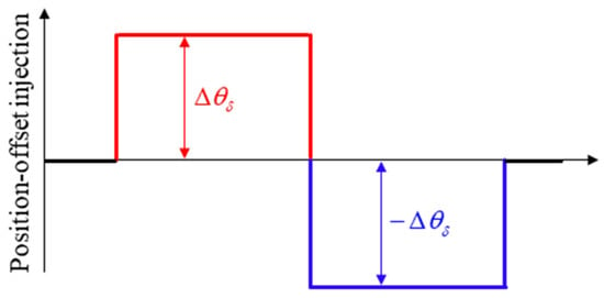
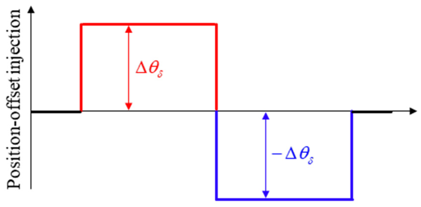
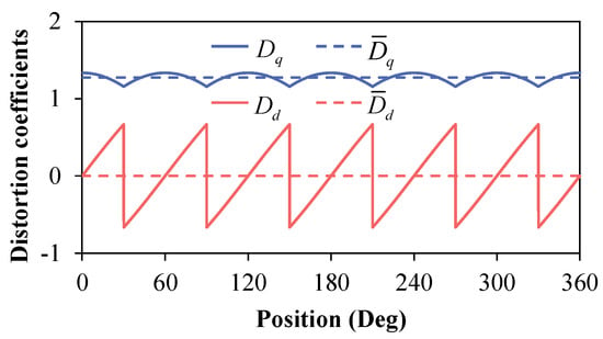
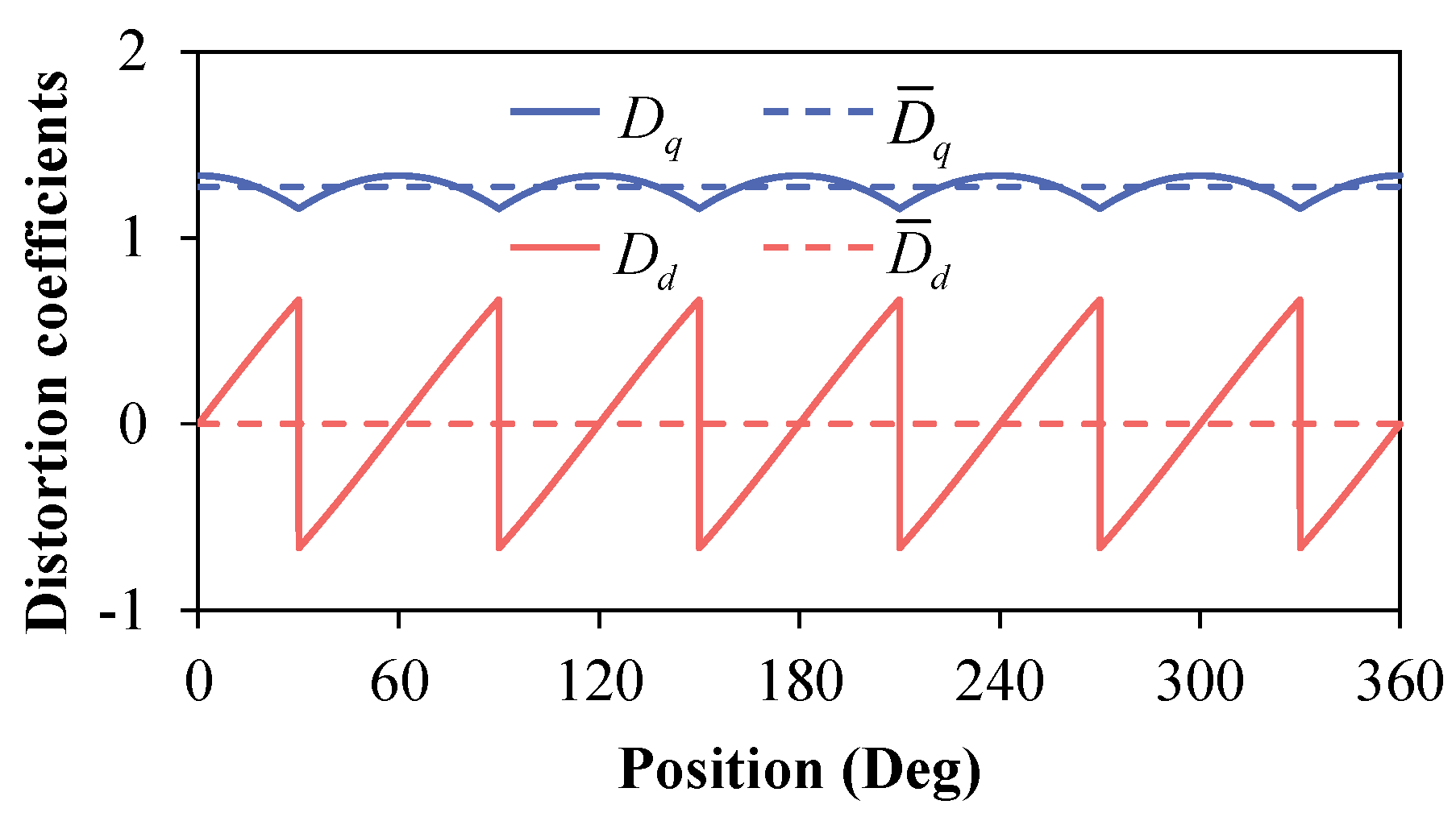
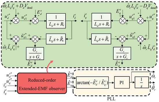
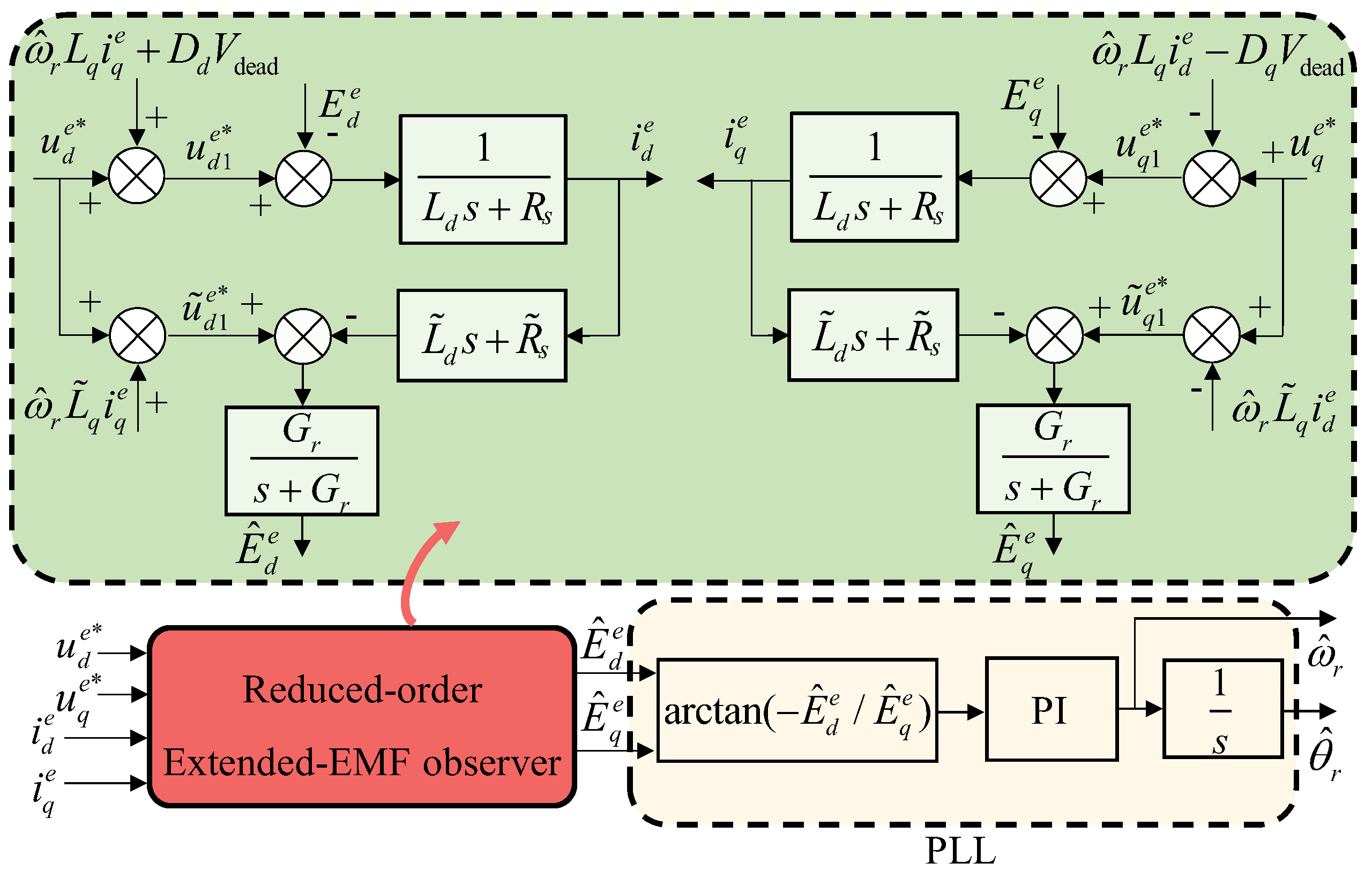
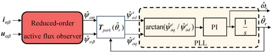
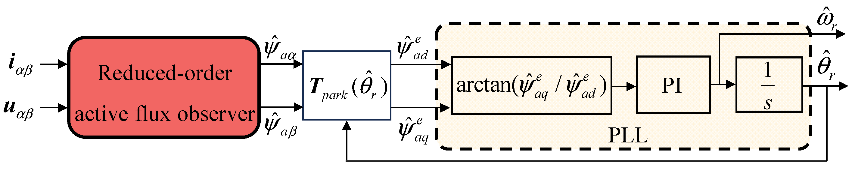
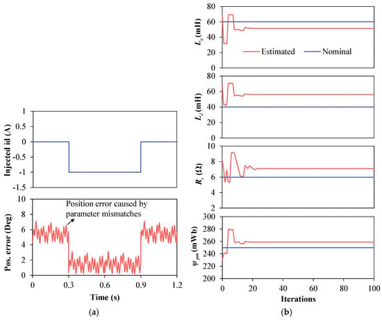
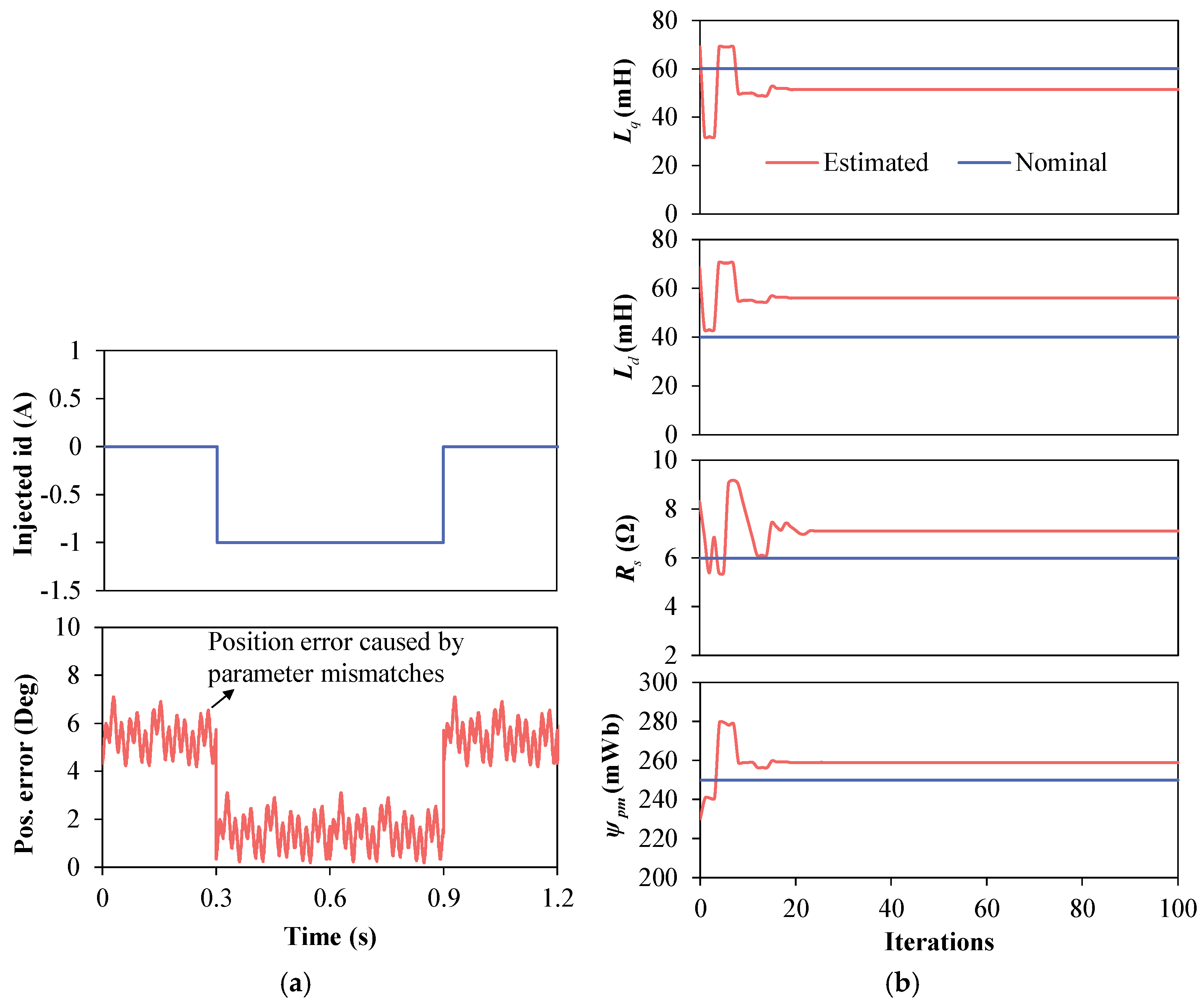
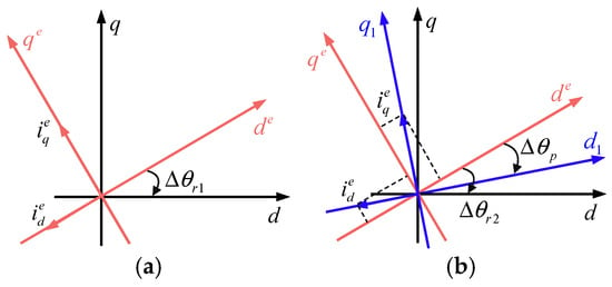
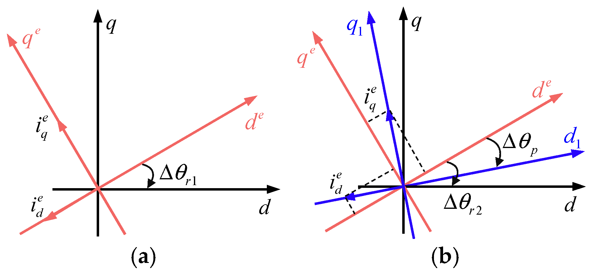
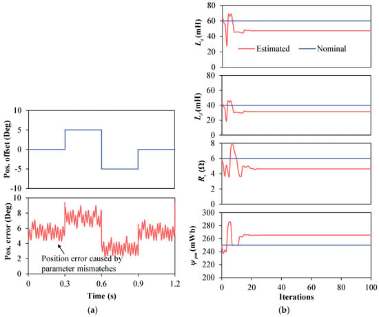
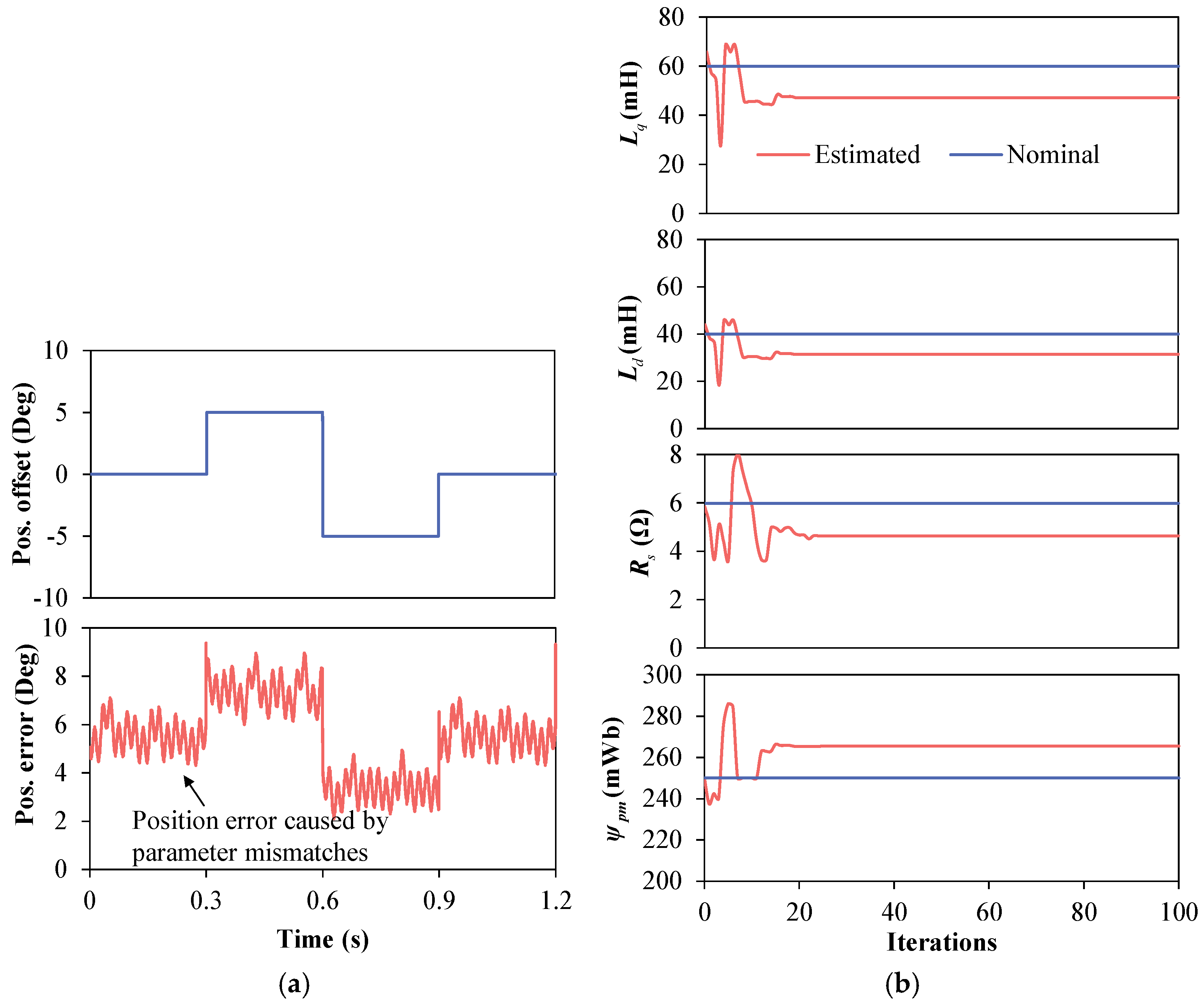
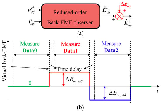
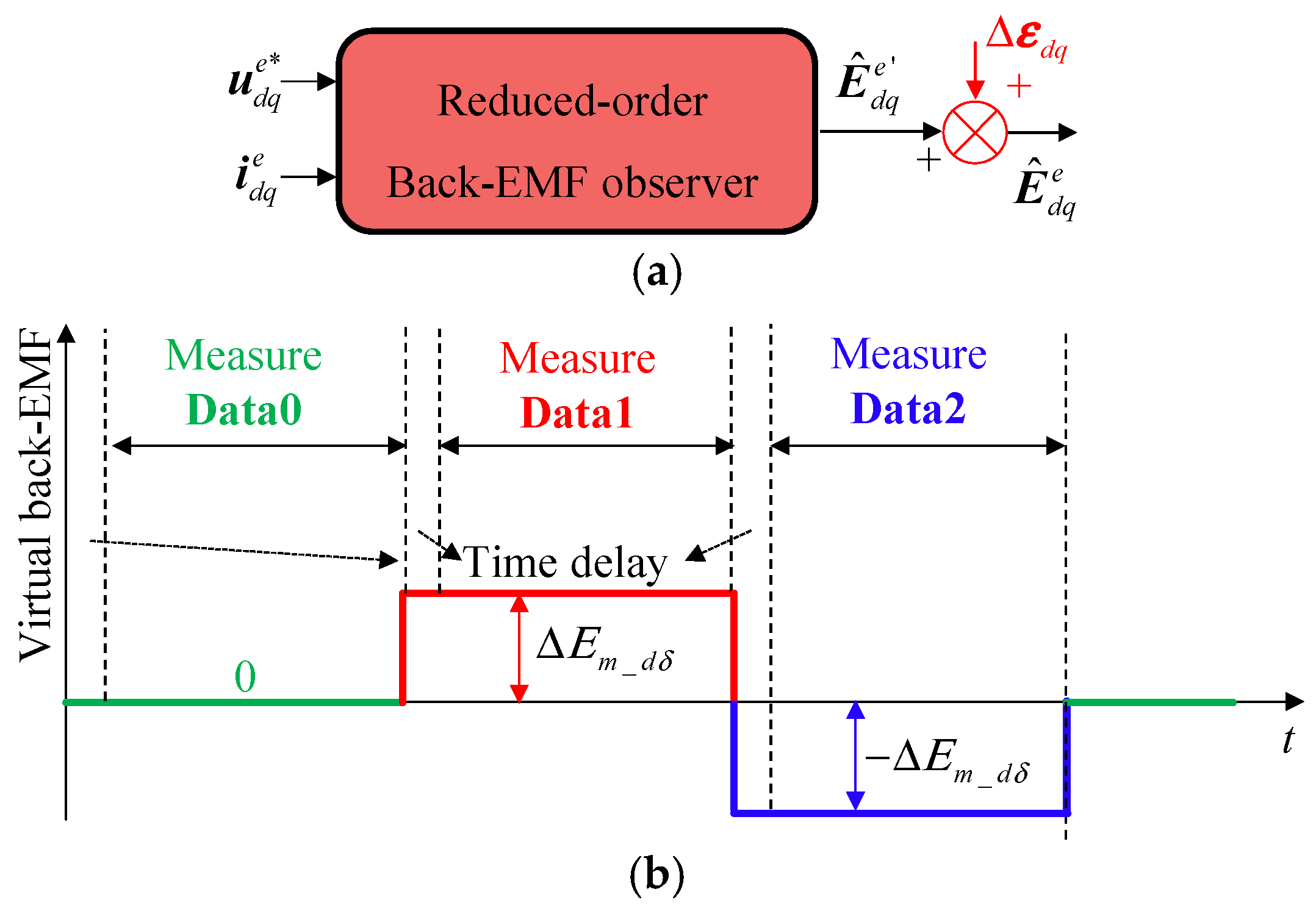
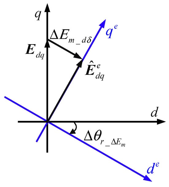
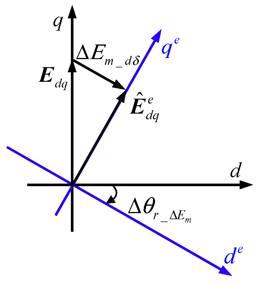
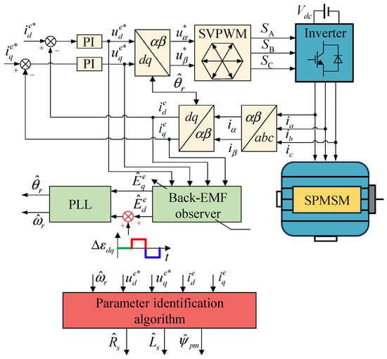
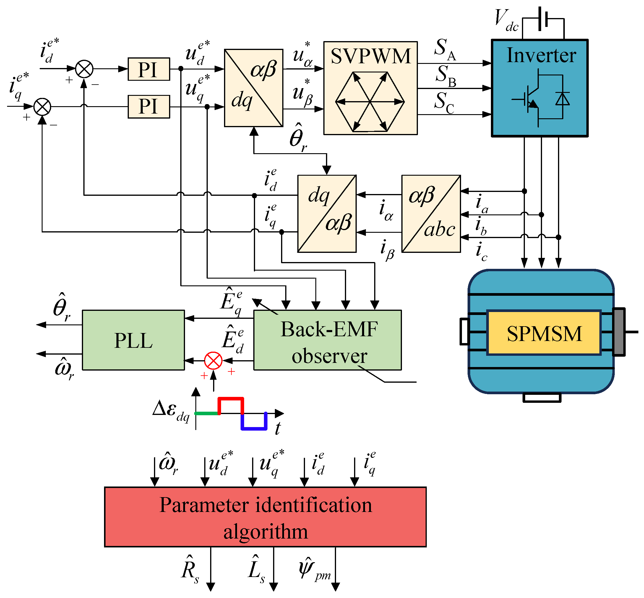
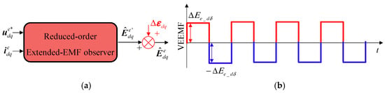
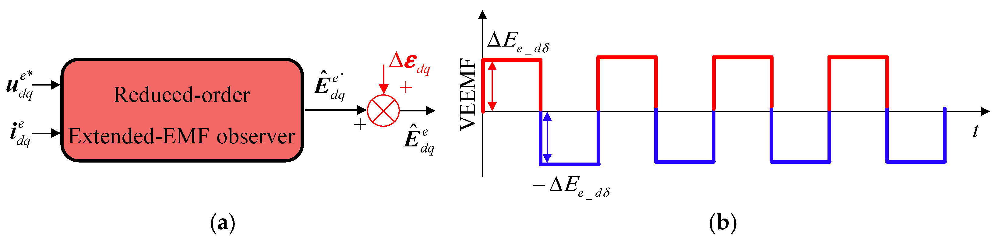
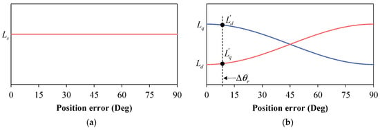
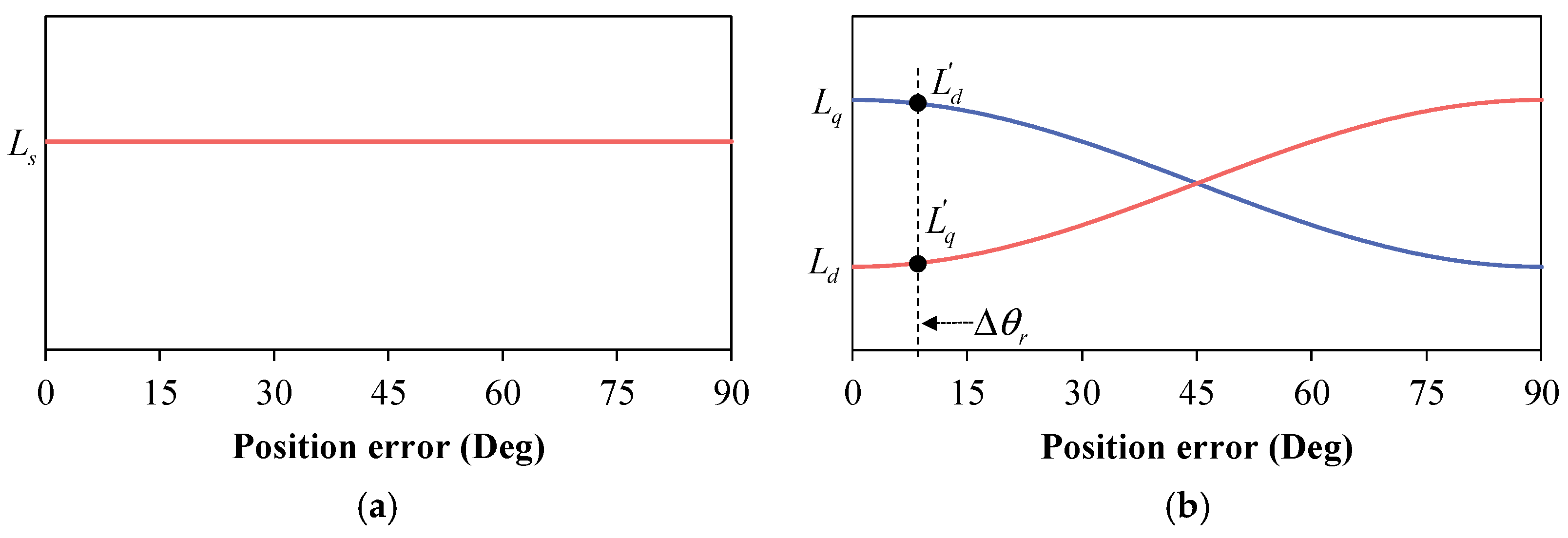
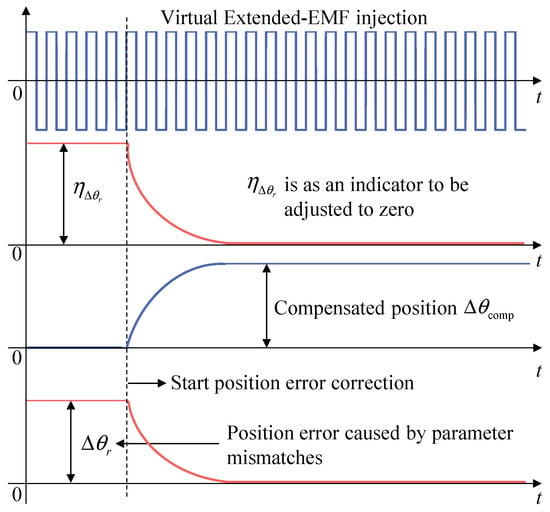
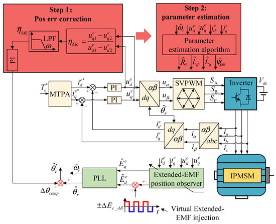
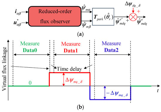
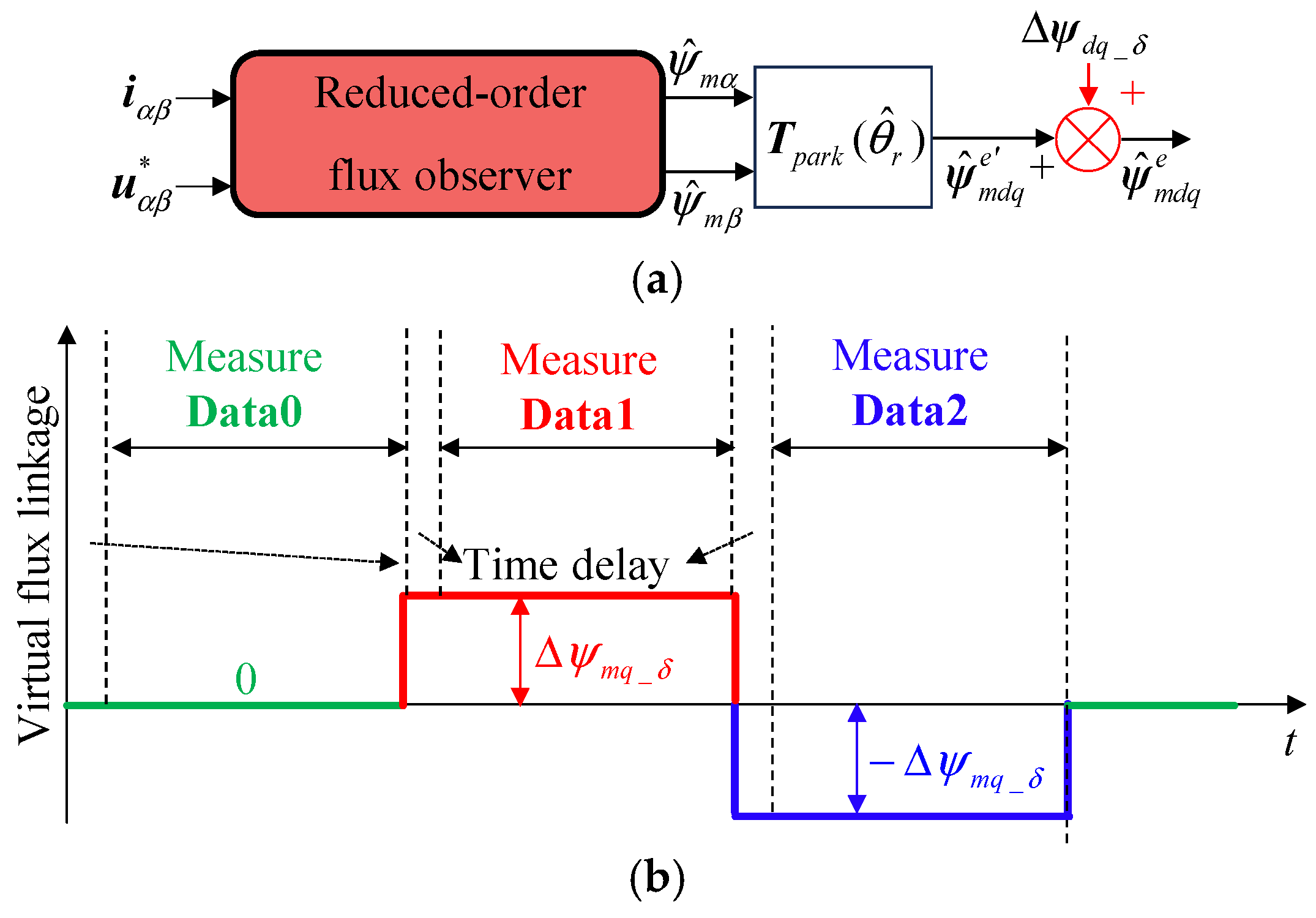
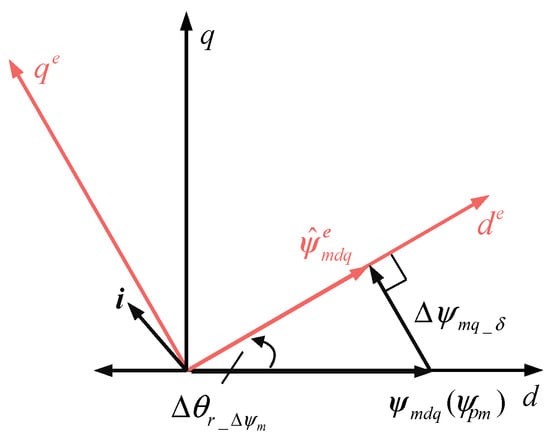
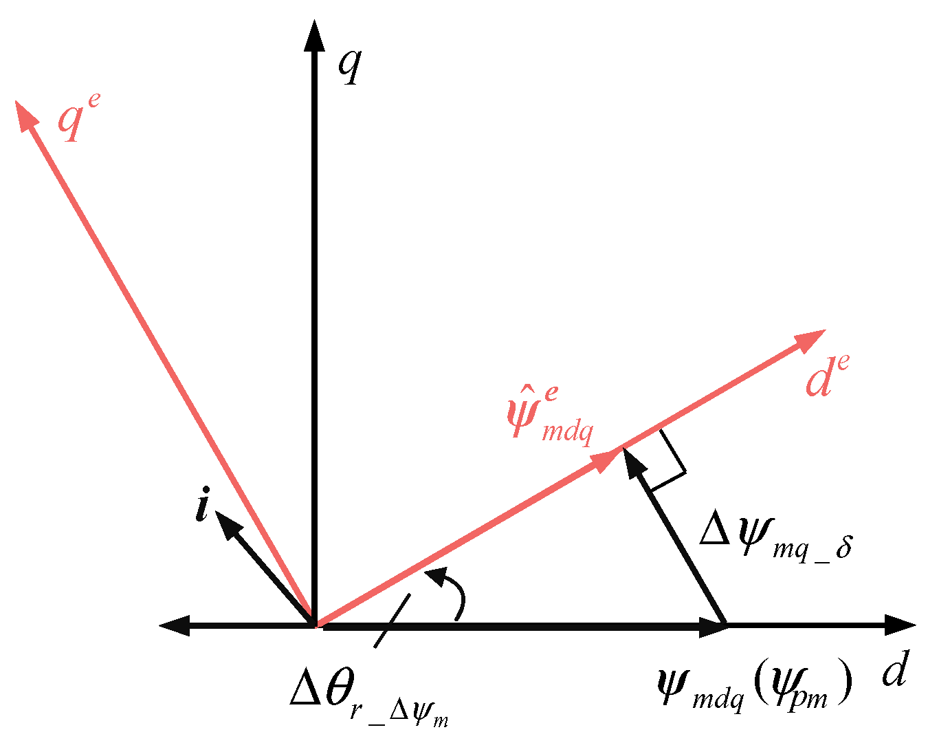
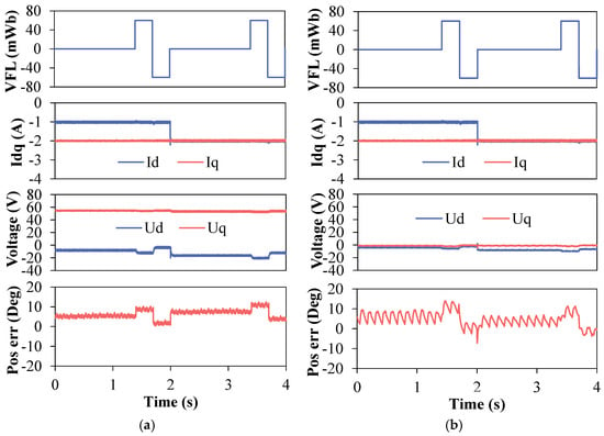
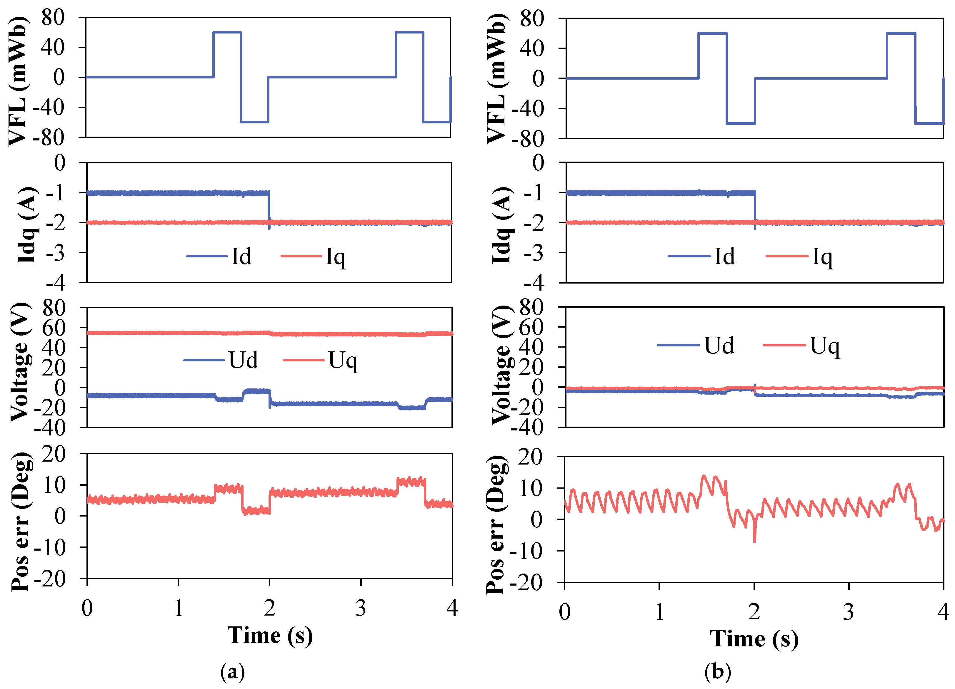
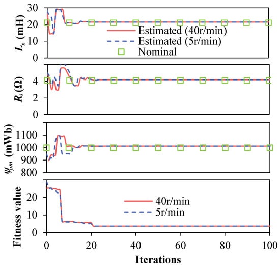
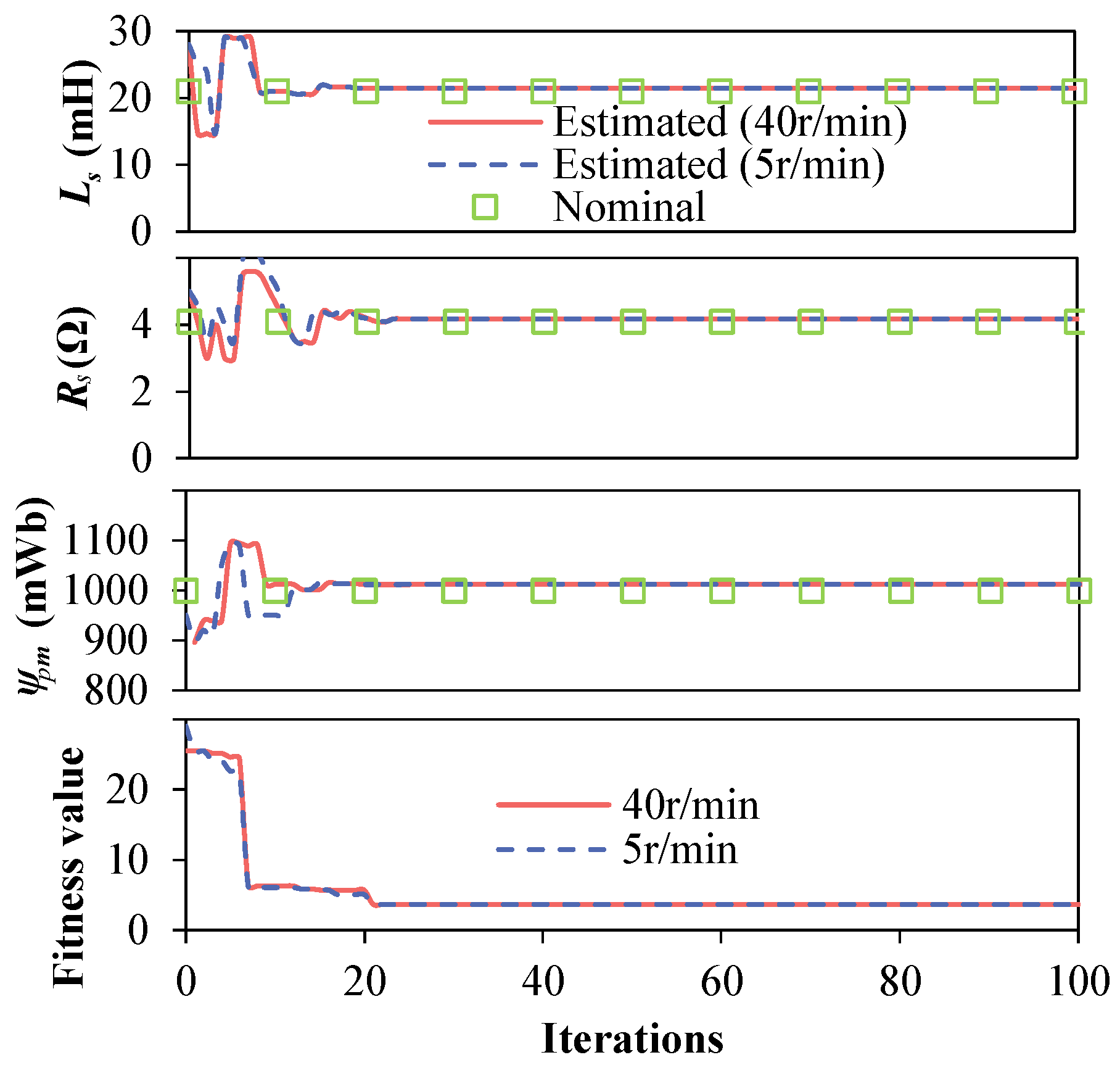
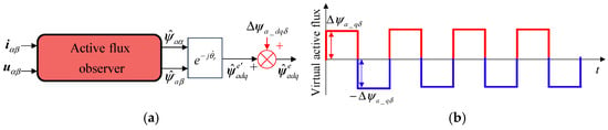
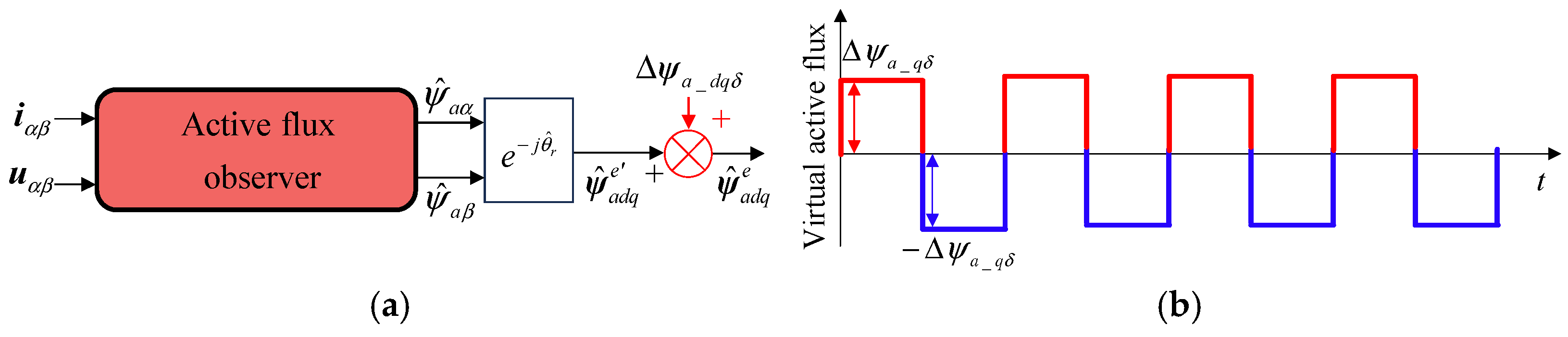
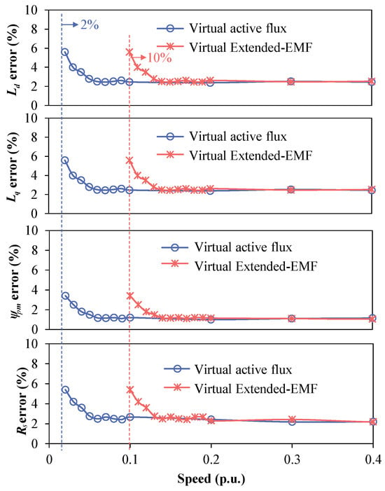
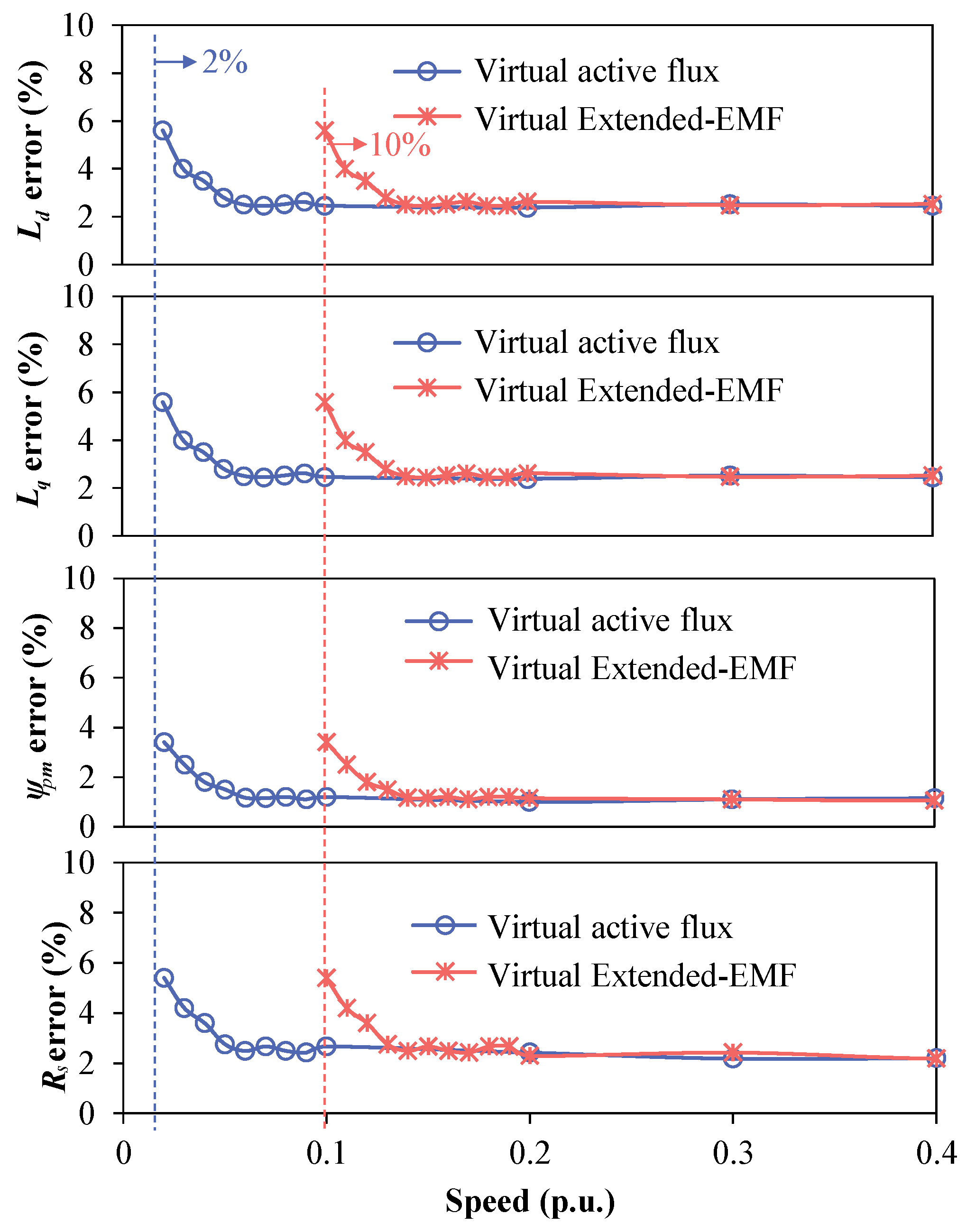
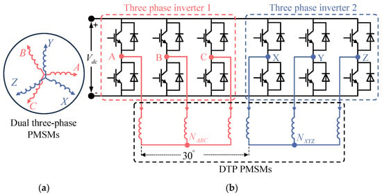
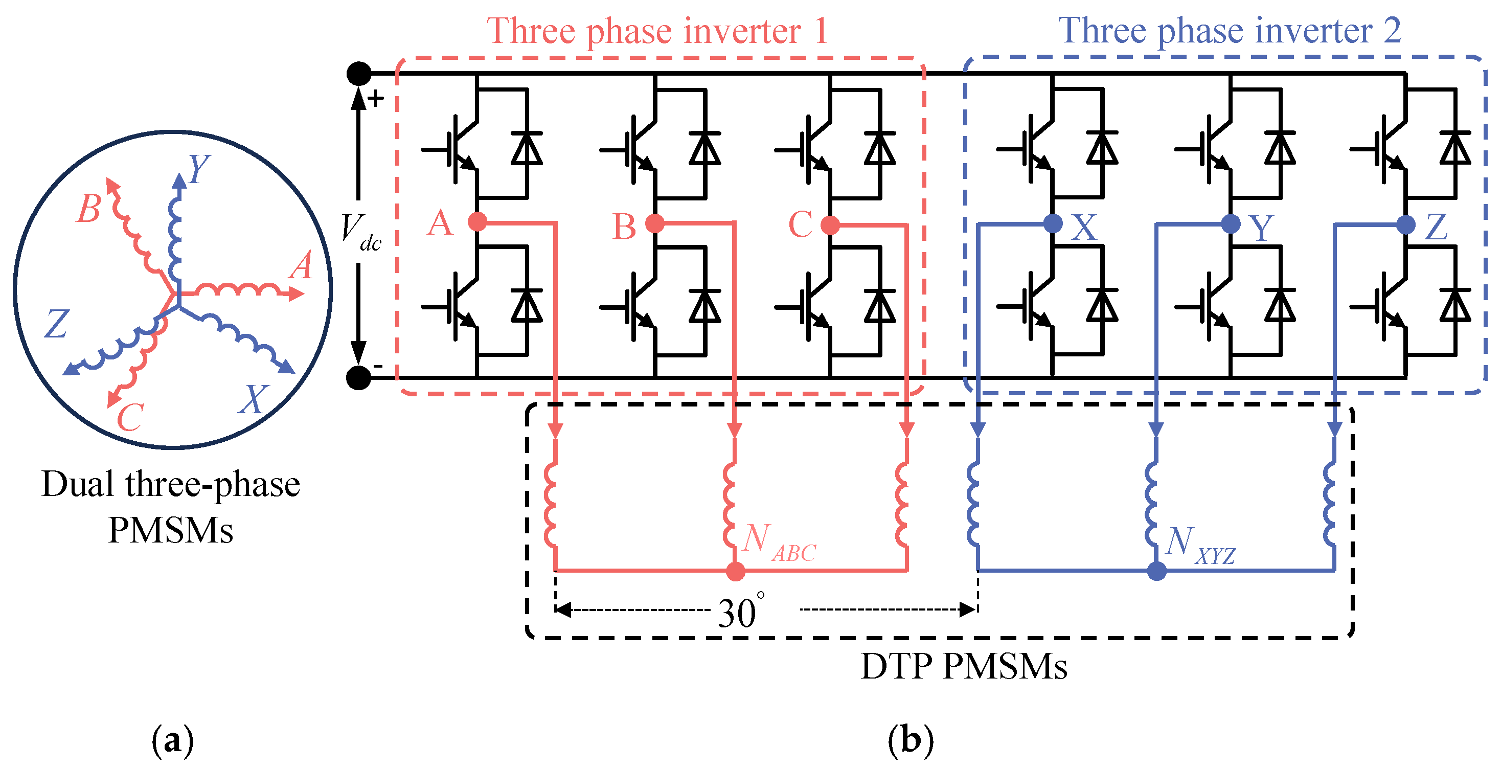
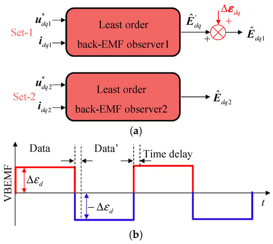
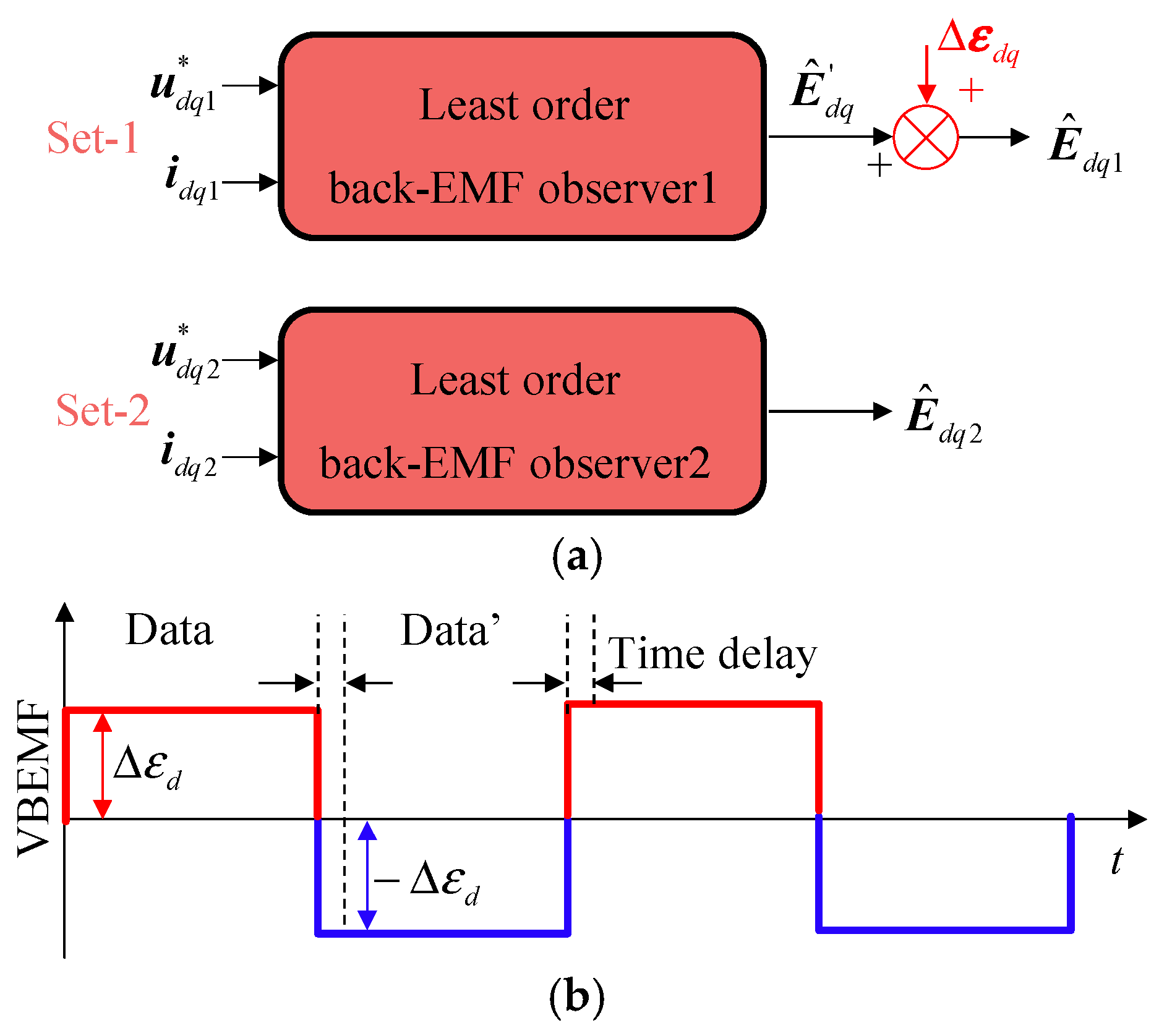
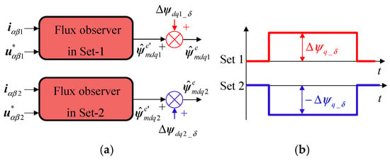
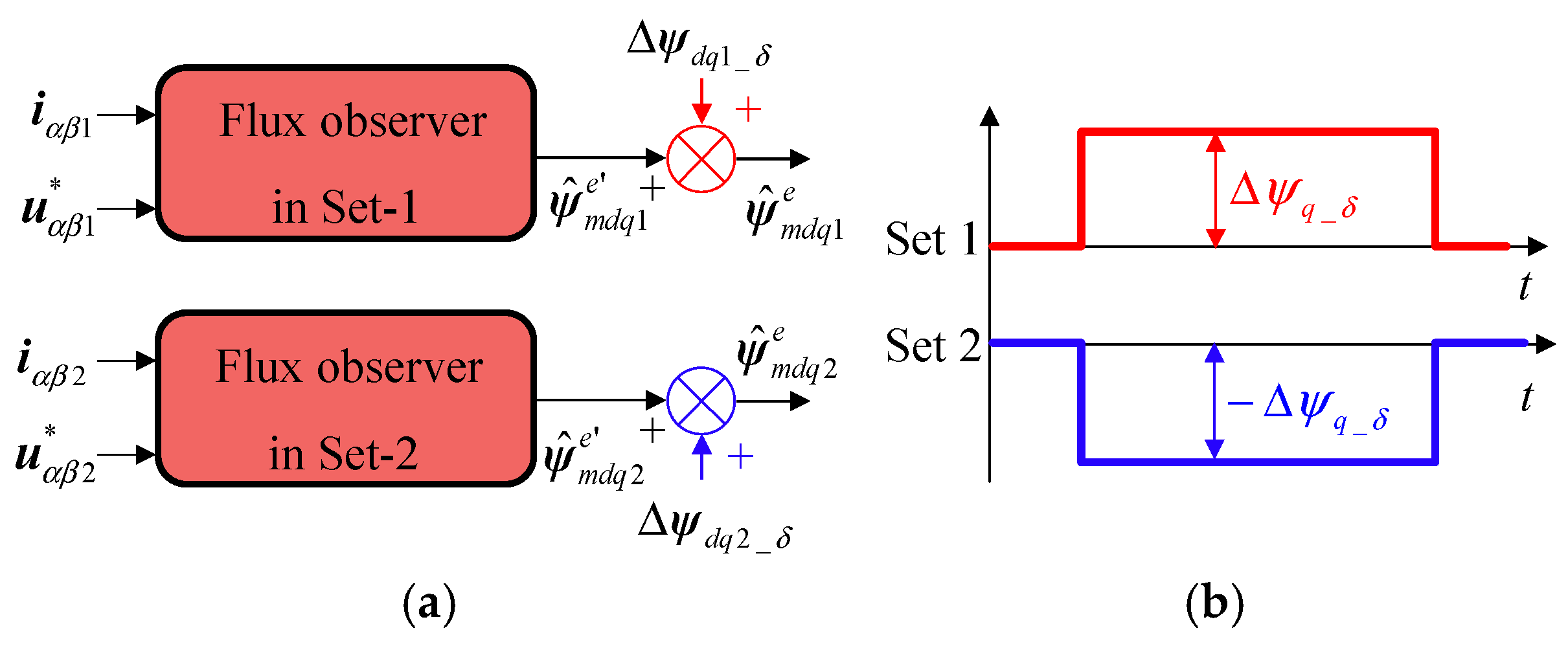

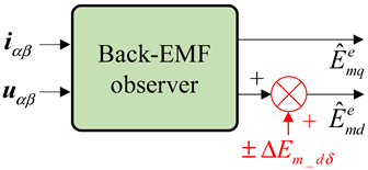
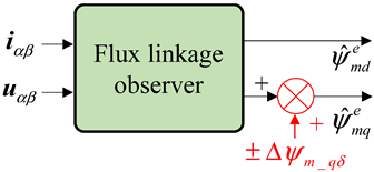
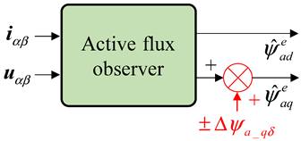
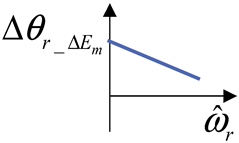
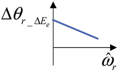
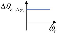
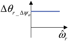
Disclaimer/Publisher’s Note: The statements, opinions and data contained in all publications are solely those of the individual author(s) and contributor(s) and not of MDPI and/or the editor(s). MDPI and/or the editor(s) disclaim responsibility for any injury to people or property resulting from any ideas, methods, instructions or products referred to in the content. |
© 2026 by the authors. Licensee MDPI, Basel, Switzerland. This article is an open access article distributed under the terms and conditions of the Creative Commons Attribution (CC BY) license.