


Abstract
To address the possible limitations of conventional energy-efficiency indicators in terms of restricted evaluation boundaries and the insufficient characterization of energy coupling and reuse processes in complex energy-utilization systems, this paper proposes a modified energy-efficiency-evaluation method based on unutilized-energy decomposition. First, a unified representation of basic energy-utilization units is established based on the concept of minimum functional units. Typical structural mappings, including series, feedback, delay, and auxiliary structures, are then introduced to describe complex energy interaction paths in a unified manner. Second, unutilized energy is distinguished from actual loss and is further decomposed into inevitable unutilized energy and potentially recoverable unutilized energy, so as to reveal the internal differences and reuse potential of energy that does not form useful output. On this basis, modified energy-efficiency indicators for downstream-utilization, feedback-recirculation, and auxiliary structures are developed, together with supporting indicators such as recovery efficiency gain, auxiliary efficiency gain, and the actual loss rate, thereby forming a comprehensive evaluation framework for complex energy-utilization systems. Finally, a gas engine combined heat and power (CHP) system is used as a case study. The results show that conventional power-generation efficiency cannot distinguish system performance differences under different heat-utilization conditions, whereas the proposed modified energy efficiency and actual loss rate can effectively reveal the effects of waste-heat utilization, thermal-load matching, and thermal-storage shifting on overall system performance. This study can provide a reference for the comprehensive energy-efficiency evaluation of combined heat and power systems, as well as other chain-type and multi-energy coupled energy-utilization systems.
1. Introduction
Improving energy-utilization efficiency is an important pathway for reducing primary energy consumption, avoiding energy waste, and supporting the low-carbon energy transition [1,2,3]. Technologies such as CHP systems, waste-heat recovery, energy storage regulation, and multi-energy collaborative utilization have been widely applied in industrial and building energy-utilization systems [4,5]. Compared with conventional single-device or single-stage conversion processes, complex energy-utilization systems usually involve multi-stage coupling and cross-period regulation. The energy flows in such systems are no longer limited to simple linear input–output relationships but exhibit stronger structural and hierarchical characteristics [6,7]. In recent years, studies on integrated energy systems, CHP systems, and storage-coupled systems have shown that multi-energy coupling, storage participation, and dynamic supply–demand matching significantly increase the complexity of energy-efficiency assessment [8,9]. Therefore, establishing a comprehensive energy-efficiency assessment method that can reflect complex energy interaction paths and the overall energy-utilization level of the system has become a key issue in energy system analysis and optimization.
Existing studies have explored the performance evaluation of complex energy-utilization systems from different perspectives. First, Mancarella [10] discussed the coupling relationships and evaluation models among different energy carriers, such as electricity, heat, and gas, from the perspective of multi-energy systems, and pointed out that multi-energy interactions increase the complexity of system performance assessments. Representative studies have also reviewed and analyzed combined cooling, heating, and power systems in terms of system configurations, performance characteristics, and optimization methods [11,12]. One group of studies has evaluated the energy conversion level and energy supply efficiency of devices or systems based on conventional energy efficiency, overall efficiency, exergy efficiency, or data envelopment analysis. Nesheim and Ertesvåg [13] discussed various efficiency indicators for CHP systems and showed that different indicators emphasize different aspects of combined electricity and heat outputs. Torchio [14] developed energy, exergy, environmental, and economic indicators for CHP system evaluation. Cong et al. [15] combined SBM-DEA with Monte Carlo simulation to evaluate the energy supply efficiency of integrated energy systems, providing a data-driven approach for efficiency assessments in multi-input and multi-output systems. Exergy efficiency complements conventional energy-efficiency assessments from the perspectives of energy quality and irreversible losses. Ertesvåg [16] compared the exergetic characteristics of different efficiency indicators for CHP systems and indicated that conventional efficiency alone is insufficient to fully reflect thermodynamic performance. Dincer and Cengel [17], Rosen and Dincer [18], and Mahian et al. [19] further illustrated the role of exergy analysis in thermal engineering and CHP system evaluations from theoretical and review-based perspectives.
Another group of studies has focused on energy cascade utilization and recovery processes, mainly including waste-heat resource identification, recovery-device performance improvement, and heat–power matching optimization. Teng et al. [20] conducted energy, exergy, and economic analyses of ORC-based CHP waste-heat recovery systems. Omara [21] reviewed the application of phase change materials in internal combustion engine waste-heat recovery and emphasized the role of thermal storage materials in alleviating the mismatch between waste-heat supply and demand. Saidur et al. [22] and Sprouse and Depcik [23] summarized internal combustion engine exhaust heat recovery technologies and organic Rankine cycle applications, respectively, indicating the technical potential of low-grade waste-heat utilization. In addition, energy storage regulation and cross-period supply–demand matching have been widely used to improve the operational flexibility of complex energy-utilization systems. Bauer et al. [24] summarized the development of thermal-energy-storage materials and systems. Miao et al. [25] and Chen et al. [26] analyzed the operating performance of power-to-heat thermal storage and CHP plants integrated with thermal energy storage, respectively, showing that storage can improve system operating conditions and alleviate heat–power coupling constraints. Yang et al. [27] further analyzed the contribution of different subsystems and conversion links to the overall energy efficiency of integrated energy systems from the perspective of marginal contribution, providing a reference for identifying weak links in system performance.
However, although existing studies provide an important foundation for the analysis of complex energy-utilization systems, several limitations remain in comprehensive energy-efficiency assessments. First, existing evaluation methods mainly focus on the final energy conversion level of devices or systems. For example, electrical efficiency mainly reflects the conversion performance on the power-generation side, whereas exergy efficiency evaluates energy quality and irreversibility, and data-driven efficiency evaluation methods, such as DEA-, SBM-DEA, or contribution-analysis-based models, are mainly used for relative efficiency comparisons among different systems, subsystems, or operating units. However, insufficient attention has been paid to the internal differences and further utilization potential of the energy that does not form useful output. In addition, studies on different coupling mechanisms, such as waste-heat recovery and energy-storage regulation, are often carried out separately for specific structures, and a unified description and assessment framework is still lacking. In complex systems, however, system boundaries and indicator meanings are often not fully consistent, which may limit the ability of conventional efficiency indicators to characterize the overall energy-utilization level of the system. Therefore, it is necessary to revisit the comprehensive energy-efficiency assessment of complex energy-utilization systems from the perspective of complex energy interaction mechanisms.
To address the above limitations, this paper proposes an energy-efficiency-assessment method based on unutilized-energy decomposition for complex energy-utilization systems, such as chain-type and multi-energy coupled systems. First, starting from energy-utilization processes and their structural relationships, the proposed method transforms complex energy interaction paths into a decomposable and combinable unified representation structure. Second, unutilized energy is distinguished from actual loss and is further divided into inevitable unutilized energy and potentially recoverable unutilized energy, so as to characterize the internal differences and reuse potential of energy that does not form useful output. On this basis, modified energy-efficiency indicators and supporting assessment indices are developed for typical energy interaction mechanisms, including downstream utilization, feedback recirculation, delay regulation, and auxiliary action. From the perspective of engineering utilization mechanisms, the proposed method aims to reveal whether potentially recoverable unutilized energy is actually recovered, shifted across time periods, or reused, thereby providing a reference for energy-saving potential identification, comprehensive energy-efficiency assessments, and operational optimization analysis of complex energy-utilization systems.
2. Representation and Structure Mapping of Energy-Utilization Units
2.1. Unified Representation of Basic Energy-Utilization Units
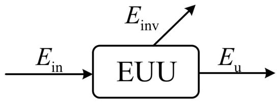
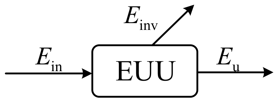
To describe different types of energy-utilization processes in a unified manner, this paper defines an energy-utilization unit (EUU) as the minimum functional unit that can independently perform a specific energy-conversion function during the process from energy input to output, as shown in Figure 1.
Figure 1.
Unified representation of an energy-utilization unit.
In an energy-utilization unit, the input energy is not completely converted into useful output that satisfies the target function. Let denote the input energy of a given unit and denote the useful output energy. According to the principle of energy conservation, the part that is not directly converted into useful output is defined as unutilized energy [28], namely
On this basis, a rectangular block diagram is adopted in this paper to represent an energy-utilization unit. The input energy enters from the left side, the useful output flows out from the right side, and the unutilized energy is extracted from the upper-right side. When multiple inputs or outputs exist, the distribution and aggregation of different branches still satisfy the energy conservation relationship. To improve readability, the main abbreviations and symbols used in the following derivations and case study are summarized in Appendix A.
2.2. Classification of Basic Energy-Utilization Units
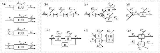
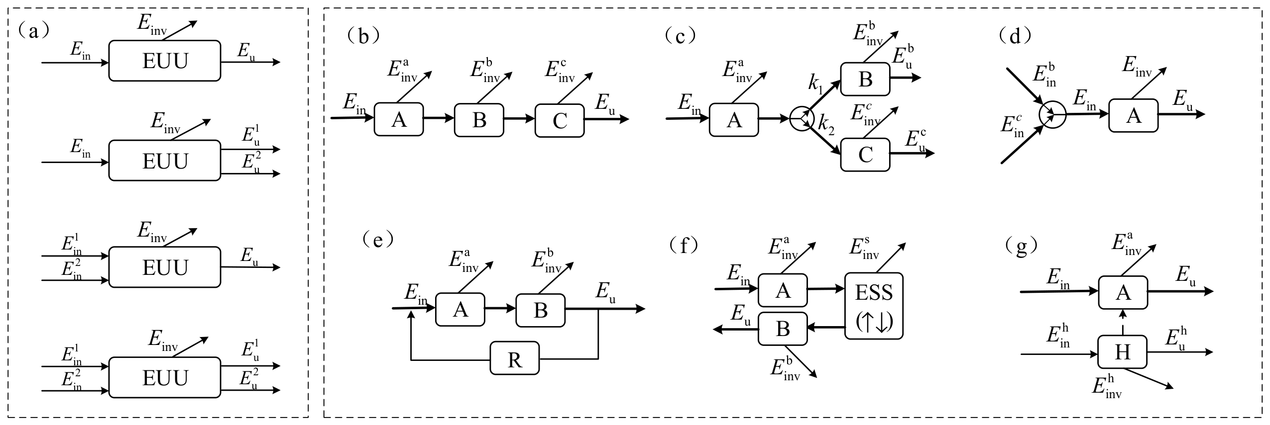
By further treating unutilized energy as an inherent output of an energy-utilization unit, basic energy-utilization units can be classified according to the number of inputs and outputs into four categories: single-input single-output (SISO) [29], single-input multiple-output (SIMO), multiple-input single-output (MISO), and multiple-input multiple-output (MIMO), as shown in Figure 2 and Table 1.
Figure 2.
Basic and typical structures of energy-utilization units. (a) Basic structures; (b) series structure; (c) radiation structure; (d) aggregation structure; (e) feedback structure; (f) delay-regulation structure; (g) auxiliary structure.
Table 1.
Unified energy accounting of basic energy-utilization units.
Among them, the SISO type is suitable for conventional single-path energy-conversion devices; the SIMO type is suitable for equipment that simultaneously produces multiple forms of energy output; the MISO type is applicable to scenarios in which multiple energy sources are aggregated to support the same load; and the MIMO type is suitable for complex systems with more significant multi-energy coupling and bidirectional energy exchange. Therefore, Table 1 should be understood as a unified representation of energy accounting boundaries and notation. Through the proposed unified representation, originally heterogeneous and discrete engineering objects can be transformed into decomposable and combinable energy-flow units, thereby laying a foundation for subsequent structural mapping and indicator definition.
2.3. Classification of Typical Structural Mappings
Complex energy-utilization systems involve not only the energy balance within individual units, but also energy interaction paths among multiple units. Therefore, the representation of basic energy-utilization units alone is insufficient to reveal the system-level energy-efficiency mechanisms.
To improve the engineering applicability of the proposed method, this paper further maps complex energy-utilization systems into several typical structures from the perspective of system combination relationships, including series, radiation, aggregation, feedback, delay-regulation, and auxiliary structures, corresponding to Figure 2b–g, respectively. In Figure 2, ESS denotes the energy-storage system, R denotes the recovery unit, and H denotes the auxiliary unit.
Among them, the series structure is the most fundamental chain-type structure, in which the useful output of the preceding unit directly serves as the input of the subsequent unit. In the radiation structure, the output of the main unit is distributed to multiple downstream branches, and the system energy efficiency is jointly affected by the branch allocation ratio and the efficiency of each branch. In the aggregation structure, multiple input sources are aggregated at a certain node to jointly support the subsequent energy-conversion process, and the evaluation focuses on multi-source contributions and overall efficiency.
The feedback structure refers to a structure in which energy leaves the main flow path and then re-enters the system to form a closed loop for reuse. When a recovery unit exists in the system, the unutilized energy generated by the original unit can be returned to the system, thereby reducing the final loss and increasing the useful system output. Therefore, the recovery unit can be regarded as a special feedback mechanism for the reuse of unutilized energy. The delay-regulation structure realizes the transfer of energy in the time dimension through an energy-storage device. In the auxiliary structure, the auxiliary unit does not directly undertake the main energy-transfer task, but affects the efficiency and loss level of the main unit by adjusting parameters or improving operating conditions.
The above structural mappings allow the proposed method to go beyond single-device efficiency analysis and further extend to the unified description of complex chain-type systems.
3. Unutilized-Energy Decomposition and Loss Analysis in Energy-Utilization Units
3.1. Classification of Unutilized Energy
To further characterize the energy-saving potential, unutilized energy can be divided into inevitable unutilized energy and potentially recoverable unutilized energy . Inevitable unutilized energy refers to the part that is determined by the principles of energy conversion, physical boundaries of the equipment, and system operating mechanisms and is in principle difficult to eliminate. Potentially recoverable unutilized energy refers to the part that can theoretically be reduced or reused through recovery, optimization, or scheduling.
3.2. Distinction Between Unutilized Energy and Actual Loss
Different from conventional descriptions, this paper emphasizes that unutilized energy is not equivalent to final loss. Unutilized energy only represents the energy that does not directly form useful output in the current unit, while part of his energy can be actually recovered only when a feasible recovery or transfer path, sufficient recovery capacity, and a receiving demand or storage space exist within the system boundary. This relationship can be expressed as follows:
where denotes the effective recovery coefficient determined by the availability of the recovery path, recovery capacity, and receiving demand. When no feasible recovery path or receiving demand exists, . When , part of it can be recovered and reused through downstream utilization.
To further clarify the difference between potentially recoverable unutilized energy and actually recovered energy, the potentially recoverable unutilized energy can be divided into two parts:
where denotes the part of potentially recoverable unutilized energy that is actually recovered and reused to form useful output, and denotes the residual part of potentially recoverable unutilized energy that is not recovered and finally becomes loss.
Accordingly, the actual loss at the system level can be defined as follows:
where represents the energy that is ultimately not utilized within the system boundary. It can be seen that unutilized energy emphasizes the energy that is not directly utilized at the unit level, whereas actual loss emphasizes the energy that is ultimately not utilized at the system level. The distinction between and further indicates that having recovery potential does not necessarily mean that the energy is actually recovered and reused. Only the part that is effectively recovered and converted into useful output can reduce the final actual loss. Distinguishing between these two concepts enables the analysis of energy-saving potential in complex systems to shift from simply reducing total losses to identifying and converting reusable energy.
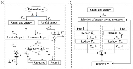
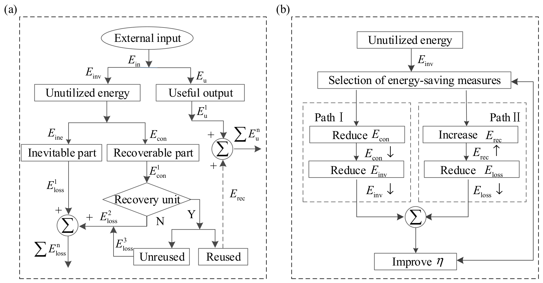
The above classification indicates that not all unutilized energy has energy-saving significance or regulation value. Instead, the key lies in the potentially recoverable part with conversion potential. Figure 3a illustrates the logical relationship among unutilized energy, recovery utilization, and final loss.
Figure 3.
Unutilized-energy decomposition, recovery-loss relationship, and energy-saving pathways. (a) Recovery-loss relationship of unutilized energy; (b) energy-saving pathways based on unutilized-energy decomposition.
Therefore, for complex systems, energy saving can be achieved from two perspectives: (1) from the formation mechanism of unutilized energy, by reducing potentially recoverable unutilized energy; and (2) from the utilization outcome of unutilized energy, by recovering as much unutilized energy as possible. Figure 3b shows the energy-saving implementation pathways based on unutilized-energy decomposition.
4. Modified Energy Efficiency for Typical Structures
4.1. Conventional Energy-Efficiency Indicators and Their Applicable Limitations
Conventional energy efficiency generally refers to the first-law energy efficiency commonly used in engineering applications. It is defined as the ratio of useful output energy to input energy under a specified system boundary:
This indicator has good interpretability when energy recovery and internal circulation are not involved. However, when unutilized energy can form new useful output in subsequent units, conventional energy efficiency may be insufficient to characterize the comprehensive energy-utilization level within the system boundary. Therefore, a modified energy-efficiency indicator is introduced in this study. To avoid the double counting of internally circulated energy and to more accurately reflect the utilization degree of energy obtained from outside the system, the initial external input energy is adopted as the unified evaluation boundary.
4.2. Modified Energy Efficiency for Recovery-Type Structures
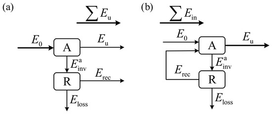
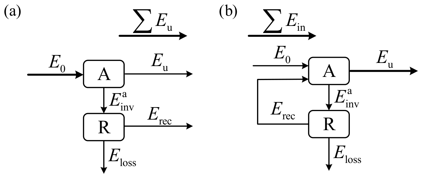
When a recovery unit exists in the system, the recovered energy may affect the system through two typical paths. As shown in Figure 4, in Figure 4a, the energy output from recovery unit re-enters the downstream unit and forms new useful output, thereby increasing the final useful energy of the system. In Figure 4b, the energy output from recovery unit R is fed back to the original unit A and participates again as a new input in the energy-conversion process, thereby enhancing the comprehensive output capability of the original unit. Since the two structures differ in their mechanisms, their modified energy-efficiency indicators and related indices should be established separately.
Figure 4.
Two typical structures through which a recovery unit affects system energy efficiency. (a) Downstream-utilization structure; (b) feedback-recirculation structure.
4.2.1. Modified Energy Efficiency for Downstream-Utilization Structures
When the output energy of the recovery unit does not return to the original unit, but enters a downstream unit and forms new useful output, the recovery unit contributes to an increase in the final useful energy of the system. For this type of structure, the modified energy efficiency for downstream utilization is defined as follows:
This definition indicates that the improvement in modified energy efficiency comes from the direct contribution of recovered energy to additional useful output. In essence, part of the energy that might otherwise become final loss is transformed into useful output of the system.
4.2.2. Modified Energy Efficiency for Feedback-Recirculation Structures
In a feedback-recirculation structure, the cumulative processed energy of the original unit increases due to feedback, whereas the external input energy of the system does not increase. Therefore, the repeated counting of internally recirculated energy must be avoided in the evaluation. The cumulative processed input of unit A consists of the initial external input of the system and the feedback-recirculated energy:
The single-pass conversion efficiency of unit A without feedback recirculation is defined as follows:
Thus, the unutilized energy generated by unit A during a single conversion process is
Let the recovery rate of recovery unit R for unutilized energy be
Substituting Equation (10) into Equation (11) yields
Substituting Equation (12) into Equation (8) yields the following relationship for the cumulative processed input of unit A:
Solving Equation (13), the cumulative processed input of unit A can be obtained as follows:
Therefore, in the feedback-recirculation structure, the recovery unit does not directly increase new external useful output. Instead, part of the unutilized energy re-enters the original unit, thereby increasing the total amount of energy actually involved in the conversion process of unit A. According to the definition of the single-pass conversion efficiency of unit A, the final useful output of the system can be expressed as follows:
The modified energy efficiency of the feedback-recirculation structure is then defined as follows:
Equation (16) shows that the modified energy efficiency of the feedback-recirculation structure is jointly determined by two factors: the single-pass conversion efficiency of the original unit A, and the recovery capability of recovery unit R for unutilized energy. When , ; and when , .
4.3. Modified Energy Efficiency for Auxiliary Structures
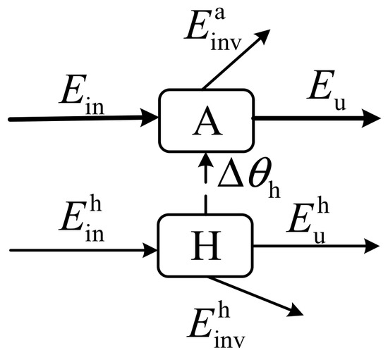
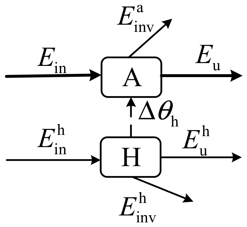
To balance mechanistic representation and model simplicity, this study adopts a single-parameter equivalent coupling method, in which the effect of an auxiliary unit is represented as the adjustment of a key parameter of the main unit, as shown in Figure 5.
Figure 5.
Auxiliary coupling structure. Note: The dashed arrow indicates the energy is not directly transferred.
For the main unit A, let its main energy-flow input be , and let the equivalent parameter that comprehensively reflects the auxiliary effect be denoted as . Depending on the specific object, this parameter may represent the power factor, voltage level, temperature, heat-transfer coefficient, excess air coefficient, or other operating variables. When no auxiliary effect is present, the key operating parameter is , and the useful output and unutilized energy of the main unit are respectively expressed as follows:
where denotes the conversion efficiency of the main unit under the benchmark parameter.
For simplicity, the parameter variation caused by the auxiliary unit is denoted as , and the operating parameter of the main unit after auxiliary action becomes . The parameter variation is related to the input energy of auxiliary unit H through a corresponding function:
where the function represents the mapping relationship between the auxiliary energy consumption and the improvement in the key parameter of the main unit.
Under auxiliary action, the useful output and unutilized energy of the main unit can be expressed as follows:
Therefore, the modified energy efficiency of the auxiliary coupling structure is defined as follows:
4.4. Modified Energy Efficiency for Delay-Regulation Structures
In addition, when surplus energy generated by an energy-utilization unit during a certain period cannot be directly consumed, it is usually converted into curtailed energy or actual loss. If this energy is transferred to a subsequent demand period through a delay-regulation unit and then utilized, it can still form useful output.
Let T denote the evaluation period. At time period t, let denote the external input energy of the system, denote the useful output energy directly formed without delay regulation, and denote the energy released across periods through the delay-regulation unit and actually utilized by the load. The modified energy efficiency of the delay-regulation structure can then be defined as follows:
where the delay-regulation process can be expressed as follows:
where denotes the stored energy in the delay-regulation unit at the beginning of time period t, denotes the stored energy at the beginning of the next time period, denotes the charged energy of the storage unit during time period t, and denotes the discharged energy of the storage unit during time period t. and are the charging and discharging efficiencies of the storage unit, respectively.
5. Comprehensive Evaluation Indicator System and Assessment Procedure
In addition to modified energy efficiency, several supporting indicators are constructed in this study to characterize the energy-utilization features of complex energy-utilization systems from different perspectives.
5.1. Composition Indicators of Unutilized Energy
- Inevitable unutilized-energy ratio
The inevitable unutilized-energy ratio is used to characterize the proportion of unutilized energy that is determined by energy conversion principles or physical equipment characteristics and is, in principle, difficult to eliminate. It is defined as follows:
- 2.
- Potentially recoverable unutilized-energy ratio
The potentially recoverable unutilized-energy ratio is used to characterize the proportion of unutilized energy that can theoretically be reduced through operation optimization, structural improvement, or recovery utilization. It is defined as follows:
5.2. Recovery Efficiency Gain
To characterize the absolute improvement in comprehensive system energy efficiency caused by the recovery unit, the recovery efficiency gain is defined as the increment of modified energy efficiency relative to conventional energy efficiency:
For the structure shown in Figure 4a, the recovery efficiency gain is
For the structure shown in Figure 4b, by taking , the recovery efficiency gain becomes
5.3. Auxiliary Efficiency Gain
To evaluate the comprehensive effect of the auxiliary unit, the benchmark energy efficiency of the system without auxiliary action is defined as follows:
Accordingly, the auxiliary efficiency gain is defined as follows:
When , the auxiliary action is regarded as a gain-type auxiliary effect. For example, a lubrication system can reduce mechanical friction in a gearbox, thereby increasing the useful output energy after lubrication. When , it indicates that although the auxiliary action improves the parameter state, it does not improve the overall system energy efficiency and can thus be regarded as a loss-type auxiliary effect. For instance, some safety relief devices maintain pressure safety by releasing working media, but part of the thermal energy carried by the high-pressure medium is also lost.
5.4. Actual Loss Rate
To reflect the proportion of the external input energy that is ultimately not utilized by the system, the actual loss rate is defined as follows:
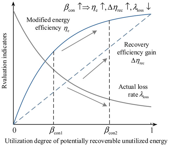
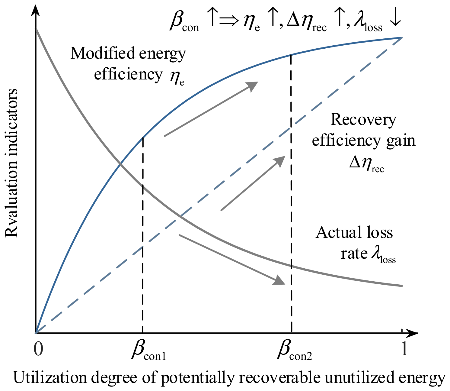
To further illustrate the internal relationships among the core evaluation indicators, Figure 6 schematically shows the variation relationships among modified energy efficiency, recovery efficiency gain, and actual loss rate.
Figure 6.
Relationship between the utilization rate of potentially recoverable unutilized energy and the core evaluation indicators. Note: The arrows indicate the trend in the indicators.
5.5. Comprehensive Evaluation Procedure
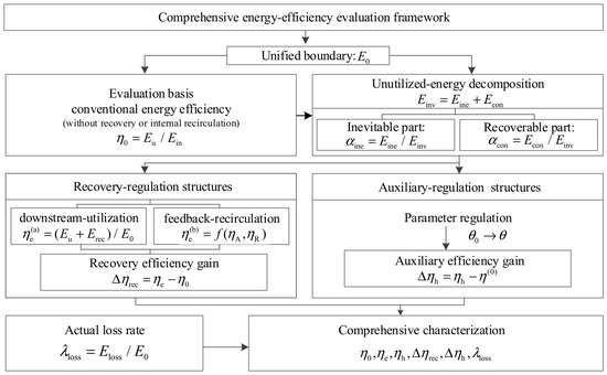
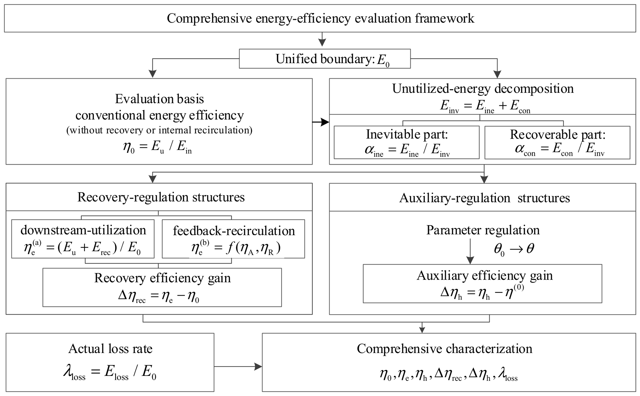
In summary, the indicator system constructed in this study is not a simple combination of several independent indicators. Instead, it takes the initial external input energy as the unified evaluation boundary and forms a systematic characterization of the comprehensive performance of complex energy-utilization systems based on unutilized-energy decomposition, structural-effect identification, and modified energy-efficiency construction. The logical relationship of the modified energy-efficiency and comprehensive evaluation indicator system is shown in Figure 7.
Figure 7.
Logical flowchart of the modified energy-efficiency and comprehensive evaluation indicator system. Note: Solid boxes denote core modules and arrows indicate logical flow.
6. Case Study
6.1. Structural Mapping and Energy-Flow Decomposition of the System
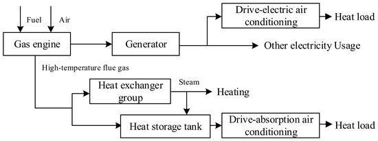
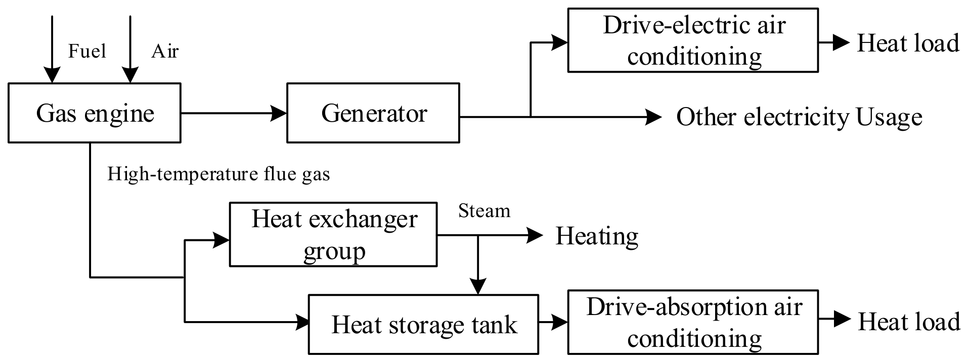
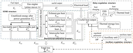
To verify the effectiveness of the proposed method, a simulation case was established based on a typical gas-engine CHP system. The schematic diagram of the case-study plant is shown in Figure 8. For internal combustion engines, gas turbines, coal-fired units, and CHP systems, waste heat contained in the exhaust gas, jacket water, lubricating oil, and cooling media can be recovered through heat exchangers, organic Rankine cycles, phase-change thermal storage, or molten-salt thermal storage [6,20,21]. In the studied system, the waste heat is recovered through heat exchangers and delivered to the thermal-load side. Under extended operating conditions, a thermal storage tank, auxiliary heating unit, and control unit are further configured to realize cross-period heat regulation and operating-state optimization.
Figure 8.
Schematic diagram of the gas-engine CHP case-study plant.
Therefore, it can cover the downstream-utilization, delay-regulation, and auxiliary structures established in this study and is representative for validating the proposed method. Specifically, the case study is designed to examine three aspects corresponding to the main objectives of this study: (1) whether the proposed method can distinguish unit-level unutilized energy from system-level actual loss under different heat-utilization conditions; (2) whether the modified energy efficiency can provide additional information compared with conventional electrical efficiency and exergy efficiency; (3) whether delay-regulation and auxiliary-regulation structures can be evaluated through the proposed supporting indicators. The relevant parameters are listed in Table 2, and the data were selected with reference to [13,20,21,30,31].
Table 2.
Types of basic energy-consuming processes and energy relationships.
According to the typical structure-mapping method proposed in this study, the gas engine CHP system can be regarded as a composite system consisting of series, downstream-utilization, delay-regulation, and auxiliary structures. As shown in Figure 9, the gas engine itself belongs to a single-input multiple-output (SIMO) structure. Its input is the chemical energy of natural gas, while its outputs include electricity and unutilized energy. The unutilized energy can be further divided into inevitable and potentially recoverable parts. Among them, radiation loss and mechanical friction are closer to inevitable unutilized energy, whereas theoretically recoverable waste heat belongs to potentially recoverable unutilized energy. Whether this part can finally be effectively utilized depends on the downstream recovery capacity and load-matching condition.
Figure 9.
Energy flow of the CHP system. Note: The arrows indicate energy categories and flow directions, respectively; the different dashed boxes correspond to different basic and typical structures. Note: The arrows indicate energy categories and flow directions, respectively; the different dashed boxes correspond to different basic and typical structures.
The heat recovery exchanger group is responsible for recovering potentially recoverable unutilized energy, and the recovered heat is directly delivered to the thermal-load side, essentially corresponding to a downstream-utilization structure. The thermal storage tank transfers heat from surplus periods to shortage periods and thus belongs to a delay-regulation structure. The auxiliary unit indirectly improves the energy efficiency of the main system by improving the operating states of the gas engine and the heat recovery process, and therefore belongs to an auxiliary structure.
6.2. Energy-Flow Calculation Model of the System
For the gas internal combustion engine, let denote the fuel input power in period , denote the electrical output power, denote the electrical efficiency, and denote the theoretical recoverable heat fraction. Then,
where is the theoretical recoverable waste-heat power, corresponding to the recoverable unutilized energy defined above. The waste heat of the gas internal combustion engine mainly includes exhaust gas heat, jacket-water heat, lubricating-oil heat, and intercooler heat. Let denote the set of waste-heat sources, , denote the proportion of the k-th heat source, and denote the corresponding heat-exchanger efficiency. Then,
where is the waste-heat power actually recovered by the heat-exchanger group. Let denote the heat load in period t. Without thermal storage, the effectively utilized heat and curtailed heat are expressed as follows:
To represent the delay-regulation structure, a thermal storage unit is introduced. Let denote the stored thermal energy and denote the maximum storage capacity. The storage state is updated as follows:
The thermal storage unit charges during heat-surplus periods and discharges during heat-deficit periods, thereby shifting part of the recoverable unutilized energy across time periods for subsequent useful heat supply. The useful heat supply after considering thermal storage can be expressed as follows:
This model corresponds to the delay-regulation structure proposed above. Its role is to improve the temporal matching between the recovered heat and heat-load demand.
For the auxiliary-regulation structure, a single-parameter equivalent coupling method is used to describe the auxiliary effect. Let denote the auxiliary power consumption and denote the auxiliary power consumption required to reach the reference auxiliary effect. The auxiliary response factor is defined as follows:
where , which is used to characterize the influence of auxiliary power consumption on the improvement of the equivalent operating parameter. Let denote the baseline parameter without auxiliary regulation, and let denote the parameter improvement under the reference auxiliary condition. Then, the equivalent parameter after auxiliary regulation can be expressed as follows:
On this basis, the equivalent improvements in electrical efficiency and heat-recovery capability caused by the auxiliary effect can be written as follows:
where and are the improvements in electrical efficiency and heat-recovery capability under the reference auxiliary condition, respectively. After considering auxiliary energy consumption, the net modified efficiency of the system is given by
6.3. Evaluation Results Under Different Heat-Utilization Conditions
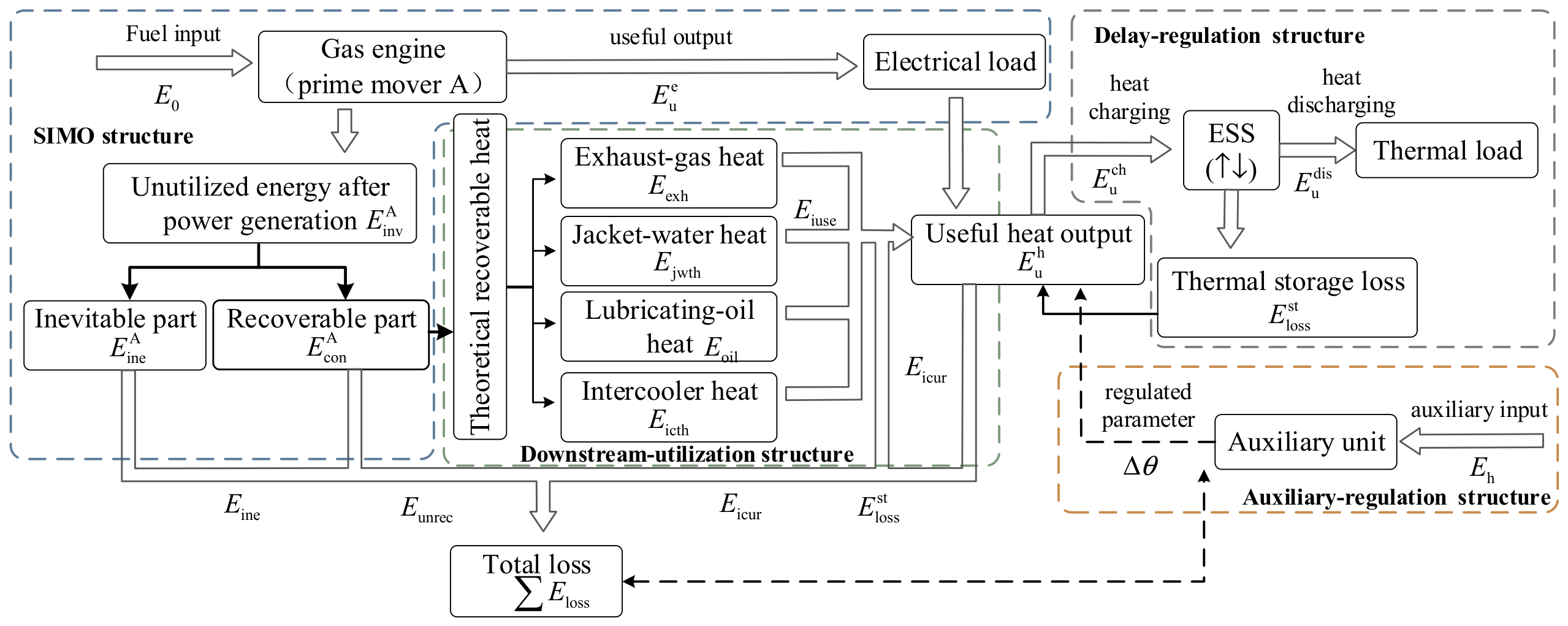
To verify the effectiveness of the proposed indicator system, three basic steady-state cases are considered. As shown in Figure 10c, Case A is a separate-supply case, in which the heat recovery unit is not put into operation and the system degenerates into a pure power-generation unit. Case B is a CHP matching case, in which the heat demand is basically matched with the recoverable heat. Case C is a CHP absorption-limited case, in which the heat demand is significantly lower than the recoverable heat.
Figure 10.
Comparison of key indicators, heat decomposition, and heat-utilization mechanisms under different operating cases. (a) Key performance indicators; (b) source-wise heat decomposition; (c) heat-utilization mechanisms under different operating cases. Note: In (a), the dashed arrows indicate the trends in efficiency for the two categories In (b), the different shades within the same color series correspond to exhaust-gas waste heat, jacket-water waste heat, lubricating-oil waste heat, and intercooler waste heat, respectively.
It should be noted that the modified energy efficiency defined in this study is a comprehensive utilization indicator based on an energy-conservation perspective. Its purpose is to characterize the degree to which the external input energy within the system boundary is finally utilized. Therefore, under the unified evaluation boundary, both the useful electrical output and the useful thermal output actually utilized by the thermal load can be included in the useful output term. This indicator reflects the comprehensive utilization level of the system and the change in final loss. It does not directly characterize the quality difference among different forms of energy and therefore should not be interpreted as efficiency in the sense of energy-quality equivalence.
As shown in Figure 10a, the conventional energy efficiency remains basically the same under the three cases. However, the modified energy efficiency and actual loss rate show significant differences. In the separate-supply case, the modified energy efficiency is 0.368 and the actual loss rate is 0.632. In the CHP matching case, the modified energy efficiency increases to 0.729, while the actual loss rate decreases to 0.271. In the CHP absorption-limited case, the modified energy efficiency decreases to 0.581, and the actual loss rate increases to 0.419. Figure 10b further explains the above differences from the perspective of heat-source composition. In Case A, only theoretical recoverable heat exists. This indicates that although the unit has waste-heat utilization potential, this potential does not enter the utilization process. In Cases B and C, the total theoretical recoverable heat is close to the total actually recovered heat, indicating that the recovery potential of the unit and the capability of the recovery devices are basically the same.
Therefore, the key to improving the performance of complex energy-utilization systems does not lie solely in the recovery capability of the equipment, but rather in whether the potentially recoverable unutilized energy can be effectively utilized.
6.4. Comparative Analysis with Existing Energy-Efficiency Indicators
To further clarify the relationship between the proposed method and existing indicators, the conventional electrical efficiency and system-level exergy efficiency are introduced as reference indicators. The conventional electrical efficiency listed in Table 3 is calculated as follows:
corresponding to Equation (5), where denotes the useful electrical output, and denotes the fuel input energy.
Table 3.
Comparison of key indicators under basic operating condition.
Based on the conventional exergy analysis method for CHP and thermal systems [16,17,18,31], the system-level exergy efficiency is calculated as the ratio of the sum of useful electrical output and useful thermal exergy to the fuel input exergy:
where denotes the useful thermal exergy, and denotes the fuel input exergy. The useful thermal exergy is calculated as follows:
where is the useful heat absorbed by the thermal load, is the ambient temperature, and is the heat-utilization temperature. The fuel input exergy is calculated as follows:
where is the chemical exergy coefficient of the fuel. In this study, natural gas is used as the fuel, and is set to 1.04 according to commonly used fuel chemical-exergy coefficients [32]. A comparison of the calculation results is shown in Table 3 below:
The comparison results show that exergy efficiency can also reflect the relative differences in system performance under different cases. Compared with conventional electrical efficiency, exergy efficiency provides a more comprehensive thermodynamic reference by considering energy quality degradation and irreversibility. However, its variation under different heat-utilization conditions is less pronounced than that of the modified energy efficiency, because exergy analysis does not explicitly track whether potentially recoverable unutilized energy is finally absorbed by the load, shifted across time periods, or converted into actual loss. In contrast, the proposed method focuses on the final engineering-utilization outcome of recoverable unutilized energy under a unified external-input boundary. Therefore, conventional electrical efficiency, exergy efficiency, and the proposed modified energy efficiency have different evaluation focuses: the first reflects power-generation conversion performance, the second evaluates energy quality and irreversibility, and the proposed indicator further reveals recovery paths, reuse outcomes, and actual loss reduction. Thus, exergy analysis and the proposed method are complementary from the perspectives of thermodynamic essence and engineering utilization mechanism, respectively.
6.5. Gain Analysis of Delay-Regulation and Auxiliary Structures
To further verify the effects of delay-regulation and auxiliary structures, cases with and without the thermal storage unit and cases with and without the auxiliary unit are respectively set based on the basic case analysis. The comprehensive system performance is then compared. The relevant results are listed in Table 4.
Table 4.
Comparison of key indicators under delay-regulation and auxiliary cases.
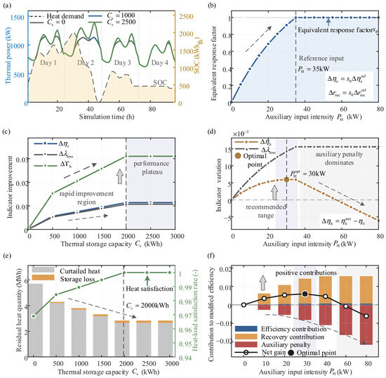
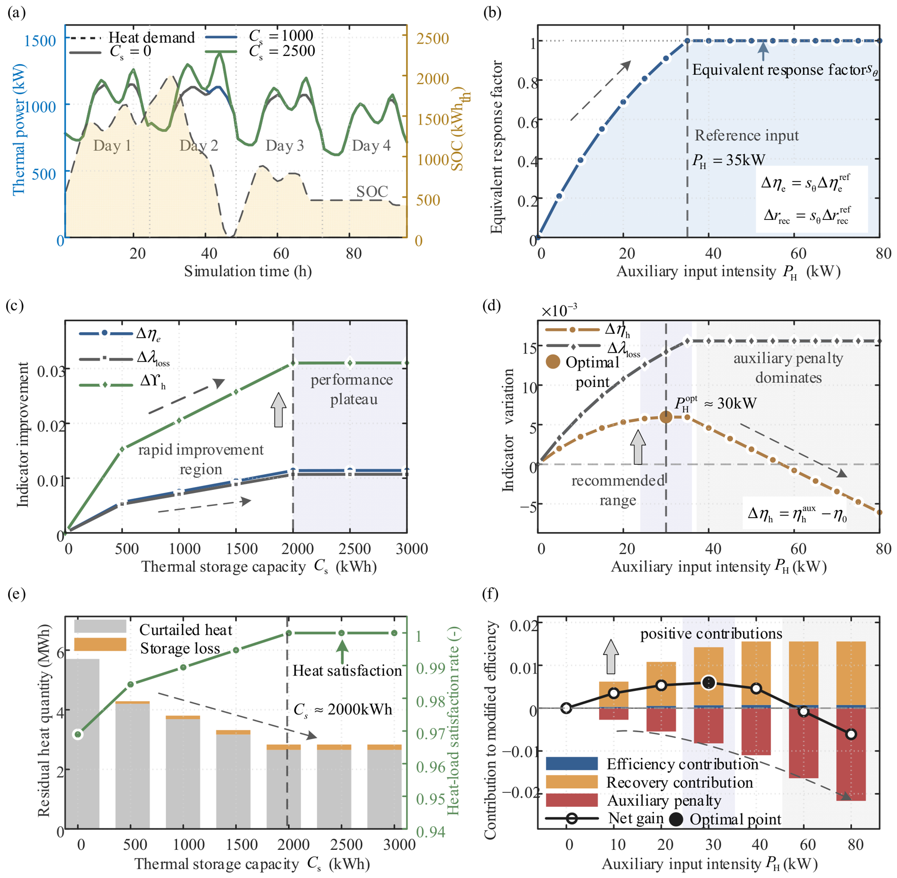
Under the continuous four-day operating condition, the modified energy efficiency without thermal storage is 0.7169, the actual loss rate is 0.2831, the heat-load satisfaction rate is 0.9689, and the cumulative rejected heat is 5702.3 kWh. After thermal storage is introduced, the storage unit does not change the first-stage energy-conversion capability of the system. Instead, it transfers surplus heat from periods of excess supply to periods of heat shortage, thereby reducing rejected heat caused by temporal mismatch.
To further analyze the effects of delay-regulation and auxiliary-regulation parameters on system performance, the thermal storage capacity and auxiliary input intensity were varied, and the corresponding changes in key indicators, residual rejected heat, and auxiliary benefit components were evaluated, as shown in Figure 11.
Figure 11.
Sensitivity analysis of delay-regulation and auxiliary-regulation structures: (a) 96 h heat-balance response; (b) equivalent auxiliary response; (c) indicator improvement with thermal storage capacity; (d) indicator gains with auxiliary input intensity; (e) residual heat and heat-load satisfaction; (f) auxiliary benefit decomposition. Note: The different color shadings distinguish thermal states or contribution types; the arrows indicate causal regulation paths or driving directions.
As the thermal storage capacity increases, the residual rejected heat gradually decreases and the heat-load satisfaction rate improves. Meanwhile, the modified-efficiency gain and the reduction in the actual loss rate increase accordingly. This indicates that the thermal storage unit can shift recoverable heat from surplus periods to subsequent demand periods, thereby reducing the actual loss caused by temporal mismatch. When the storage capacity exceeds approximately 2000 kWh, the main heat-supply mismatch has been largely mitigated and further increasing the storage capacity provides limited additional benefit.
For the auxiliary-regulation structure, the equivalent response factor increases with the auxiliary input intensity and gradually approaches saturation. The gross modified-efficiency gain and the reduction in the actual loss rate also increase first and then tend to stabilize. In contrast, because auxiliary regulation entails additional energy consumption, the net efficiency gain first increases and then decreases. Therefore, the delay-regulation structure mainly improves system performance by shifting recoverable heat across time periods, whereas the effectiveness of auxiliary regulation depends on the balance between the performance improvement of the main system and the additional auxiliary energy consumption.
Overall, the basic operating cases show that the proposed modified energy efficiency and actual loss rate can distinguish different final utilization outcomes of recovered heat, whereas conventional electrical efficiency remains unchanged. The comparison with exergy efficiency further indicates that the proposed method provides additional engineering-utilization information on recovery paths and actual loss reduction. The delay-regulation and auxiliary-regulation analyses demonstrate that the proposed indicators can also describe cross-period heat shifting and auxiliary-input effects. Therefore, the case study supports the applicability of the proposed framework to complex energy-utilization systems involving waste-heat recovery, storage shifting, and auxiliary regulation.
7. Conclusions
This study proposed a modified energy-efficiency assessment framework for complex energy-utilization systems based on unutilized-energy decomposition. By introducing the concept of minimum functional units, the proposed framework provides a unified representation of basic energy-utilization processes and maps complex energy interactions into several typical structures. In this way, multi-stage and multi-energy coupling relationships can be transformed into decomposable and combinable energy-flow paths, providing a consistent modeling basis for efficiency correction and comprehensive performance assessment.
The main contribution of this study is the distinction between unutilized energy and actual loss. Unutilized energy was further decomposed into inevitable unutilized energy and potentially recoverable unutilized energy. This distinction indicates that the energy-saving potential of a complex energy-utilization system depends not only on reducing the total amount of unutilized energy, but also on whether the recoverable part can be reused through recovery, feedback, temporal shifting, or auxiliary regulation. Based on this mechanism, modified energy-efficiency indicators were developed.
A gas-engine CHP system was used to validate the proposed framework. The results showed that the proposed modified energy efficiency and actual loss rate effectively reflected whether recoverable unutilized energy was finally converted into useful output or actual loss. In the matched CHP case, the modified energy efficiency increased from 0.3680 to 0.7291, while the actual loss rate decreased from 0.6320 to 0.2709. The analyses of delay-regulation and auxiliary-regulation structures further demonstrated that thermal storage can improve system performance by shifting recoverable heat across time periods, whereas excessive auxiliary input may offset the positive efficiency improvement of the main system.
The proposed method provides a complementary engineering-utilization perspective for the assessment of CHP systems, waste-heat recovery systems, and other chain-type or multi-energy coupled energy-utilization systems. This method expands upon existing assessment methods by focusing on the ultimate utilization of potentially recoverable, untapped energy and its conversion into actual losses. Future work will apply the proposed framework to more industrial and integrated energy systems, improve the parameter determination method under dynamic operating conditions, and explore its potential for online energy-saving diagnosis and performance assessment.
Author Contributions
Conceptualization, Y.Z. (Yongqiang Zhu) and Y.Z. (Yue Zhao); methodology, Y.Z. (Yongqiang Zhu) and Y.Z. (Yue Zhao); formal analysis, Y.Z. (Yue Zhao) and Y.L.; investigation, Y.L.; validation, Y.Z. (Yue Zhao); writing—original draft preparation, Y.Z. (Yue Zhao); writing—review and editing, Y.Z. (Yue Zhao); visualization, Y.Z. (Yue Zhao) and Y.L. All authors have read and agreed to the published version of the manuscript.
Funding
This research received no external funding.
Data Availability Statement
The original contributions presented in the study are included in the article, further inquiries can be directed to the corresponding author.
Conflicts of Interest
The authors declare no conflicts of interest.
Appendix A
Table A1 summarizes the main abbreviations, energy variables, exergy variables, efficiency indicators, and time-dependent variables used in this study.
Table A1.
Nomenclature of abbreviations and symbols used in this study.
References
- Patterson, M.G. What is energy efficiency? Concepts, indicators and methodological issues. Energy Policy 1996, 24, 377–390. [Google Scholar] [CrossRef]
- Sorrell, S. Reducing energy demand: A review of issues, challenges and approaches. Renew. Sustain. Energy Rev. 2015, 47, 74–82. [Google Scholar] [CrossRef]
- International Energy Agency. Energy Efficiency Indicators: Essentials for Policy Making; IEA: Paris, France, 2014. [Google Scholar]
- Guo, F.R.; Liu, H.H.; Song, W.; Cui, W.; Li, M.; Wang, X.; Wu, Z. Economic analysis of a combined heat and power system based on phase change thermal storage and solid-state hydrogen storage. Therm. Power Gener. 2026, 55, 59–67. (In Chinese) [Google Scholar] [CrossRef]
- Zuo, Q.Y.; Qin, X.G.; An, W.Z.; Liu, P.C.; Meng, W.J.; Wang, X.; Tian, H. Design and experiment of a two-stage waste heat recovery system for internal combustion engines. Intern. Combust. Engine Eng. 2026, 47, 58–64. (In Chinese) [Google Scholar] [CrossRef]
- Li, B.; Wang, S.-S.; Wang, K.; Song, L. Thermo-economic analysis of a combined cooling, heating and power system based on carbon dioxide power cycle and absorption chiller for waste heat recovery of gas turbine. Energy Convers. Manag. 2020, 224, 113372. [Google Scholar] [CrossRef]
- Yao, Y.; Shi, L.; Tian, H.; Wang, X.; Sun, X.; Zhang, Y.; Wu, Z.; Sun, R.; Shu, G. Combined cooling and power cycle for engine waste heat recovery using CO2-based mixtures. Energy 2022, 240, 122471. [Google Scholar] [CrossRef]
- Su, H.; Huang, Q.; Wang, Z. An energy efficiency index formation and analysis of integrated energy system based on exergy efficiency. Front. Energy Res. 2021, 9, 723647. [Google Scholar] [CrossRef]
- Ma, T.; Li, M.J.; Fan, C.H.; Dong, H.S. A novel real-time dynamic performance evaluation and capacity configuration optimization method of generation-storage-load for integrated energy system. Appl. Energy 2024, 374, 123896. [Google Scholar] [CrossRef]
- Mancarella, P. MES (multi-energy systems): An overview of concepts and evaluation models. Energy 2014, 65, 1–17. [Google Scholar] [CrossRef]
- Wu, D.W.; Wang, R.Z. Combined cooling, heating and power: A review. Prog. Energy Combust. Sci. 2006, 32, 459–495. [Google Scholar] [CrossRef]
- Cho, H.; Smith, A.D.; Mago, P. Combined cooling, heating and power: A review of performance improvement and optimization. Appl. Energy 2014, 136, 168–185. [Google Scholar] [CrossRef]
- Nesheim, S.J.; Ertesvåg, I.S. Efficiencies and indicators defined to promote combined heat and power. Energy Convers. Manag. 2007, 48, 1004–1015. [Google Scholar] [CrossRef]
- Torchio, M.F. Energy-exergy, environmental and economic criteria in combined heat and power plants: Indexes for the evaluation of the cogeneration potential. Energies 2013, 6, 2686–2708. [Google Scholar] [CrossRef]
- Cong, D.; Liang, L.L.; Jing, S.X.; Han, Y.; Geng, Z.; Chu, C. Energy supply efficiency evaluation of integrated energy systems using novel SBM-DEA integrating Monte Carlo. Energy 2021, 231, 120834. [Google Scholar] [CrossRef]
- Ertesvåg, I.S. Exergetic comparison of efficiency indicators for combined heat and power (CHP). Energy 2007, 32, 2038–2050. [Google Scholar] [CrossRef]
- Dincer, I.; Cengel, Y.A. Energy, entropy and exergy concepts and their roles in thermal engineering. Entropy 2001, 3, 116–149. [Google Scholar] [CrossRef]
- Rosen, M.A.; Dincer, I. Exergy as the confluence of energy, environment and sustainable development. Exergy 2001, 1, 3–13. [Google Scholar] [CrossRef]
- Mahian, O.; Mirzaie, M.R.; Kasaeian, A.; Mousavi, S.H. Exergy analysis in combined heat and power systems: A review. Energy Convers. Manag. 2020, 226, 113467. [Google Scholar] [CrossRef]
- Teng, S.; Wang, M.; Xi, H.; Wen, S. Energy, exergy, economic analysis, optimization and comparison of different ORC based CHP systems for waste heat recovery. Case Stud. Therm. Eng. 2021, 28, 101444. [Google Scholar] [CrossRef]
- Omara, A.A.M. Phase change materials for waste heat recovery in internal combustion engines: A review. J. Energy Storage 2021, 44, 103421. [Google Scholar] [CrossRef]
- Saidur, R.; Rezaei, M.; Muzammil, W.K.; Hassan, M.H.; Paria, S.; Hasanuzzaman, M. Technologies to recover exhaust heat from internal combustion engines. Renew. Sustain. Energy Rev. 2012, 16, 5649–5659. [Google Scholar] [CrossRef]
- Sprouse, C.; Depcik, C. Review of organic Rankine cycles for internal combustion engine exhaust waste heat recovery. Appl. Therm. Eng. 2013, 51, 711–722. [Google Scholar] [CrossRef]
- Bauer, T.; Steinmann, W.-D.; Laing, D.; Tamme, R. Thermal energy storage materials and systems. Annu. Rev. Heat Transf. 2012, 15, 131–177. [Google Scholar] [CrossRef]
- Miao, L.; Liu, M.; Zhang, K.; Zhao, Y.; Yan, J. Energy, exergy, and economic analyses on coal-fired power plants integrated with the power-to-heat thermal energy storage system. Energy 2023, 284, 129236. [Google Scholar] [CrossRef]
- Chen, C.; Ge, Z.; Zhang, Y. Study of combined heat and power plant integration with thermal energy storage for operational flexibility. Appl. Therm. Eng. 2023, 219, 119537. [Google Scholar] [CrossRef]
- Yang, S.; Chen, M.; Zuo, Q. A marginal contribution theory-based energy efficiency contribution analysis for integrated energy system. Front. Energy Res. 2021, 9, 723665. [Google Scholar] [CrossRef]
- Zhu, Y.Q.; Li, X.Y. Research on energy saving effect evaluation and energy saving potential analysis indicators. China Energy 2023, 45, 5–17. (In Chinese) [Google Scholar]
- Zhu, Y.Q.; Gao, C.G. General representation of energy relationship in energy-using systems and its influencing factors. Electr. Appar. Energy Effic. Manag. Technol. 2020, 4, 99–105. (In Chinese) [Google Scholar]
- Hu, W.T.; Sun, R.Q.; Zhang, K.Z.; Liu, M.; Yan, J. Thermoeconomic analysis and multiple parameter optimization of a combined heat and power plant based on molten salt heat storage. J. Energy Storage 2023, 72, 108698. [Google Scholar] [CrossRef]
- Zhao, S.F.; Wang, W.S.; Ge, Z.H. Energy and exergy evaluations of a combined heat and power system with a high back-pressure turbine under full operating conditions. Energies 2020, 13, 4484. [Google Scholar] [CrossRef]
- Szargut, J.; Morris, D.R.; Steward, F.R. Exergy Analysis of Thermal, Chemical, and Metallurgical Processes; Hemisphere Publishing Corporation: New York, NY, USA, 1988. [Google Scholar]

Disclaimer/Publisher’s Note: The statements, opinions and data contained in all publications are solely those of the individual author(s) and contributor(s) and not of MDPI and/or the editor(s). MDPI and/or the editor(s) disclaim responsibility for any injury to people or property resulting from any ideas, methods, instructions or products referred to in the content. |
© 2026 by the authors. Licensee MDPI, Basel, Switzerland. This article is an open access article distributed under the terms and conditions of the Creative Commons Attribution (CC BY) license.