


Abstract
In this paper, we address shaft oscillations and grid-connected oscillation frequency coupling in doubly fed induction generators (DFIGs) under DC-link dynamics. A comprehensive DFIG shaft system model incorporating DC-link dynamics is established, and frequency coupling is analyzed. From our findings, we reached the following conclusions: (a) DC-link voltage fluctuations alter electromagnetic torque through rotor-side converter (RSC) and grid-side converter (GSC) coupling, affecting shaft dynamics; (b) DC-link dynamics compromise grid connection stability by influencing both GSC and RSC output voltages. To mitigate these effects, a DC-link dynamics suppression module is proposed. Simulations confirm that in maximum power point tracking (MPPT) mode, the module enhances electrical positive damping and improves shaft stability. In constant power mode, its stabilizing effect is comparatively limited. The suppression module effectively mitigates grid-connected frequency coupling during DC-link voltage fluctuations.
1. Introduction
With the advancement of wind power technology, doubly fed induction generators (DFIGs) have become the mainstream wind turbine configuration because of their cost-effectiveness, and their market penetration continues to increase [1]. However, the high penetration of wind power integration has introduced a series of grid stability challenges. Particularly notable is the sub-synchronous oscillation (SSO) phenomenon caused by the interaction between the DFIG shaft system, electrical components, and grid connection [2,3].
Practical engineering cases demonstrate that SSO can trigger large-scale wind farm disconnection incidents. For instance, in July 2015, a sub-/super-synchronous oscillation event occurred in Hami, Xinjiang, China, with active power oscillations varying between 27 Hz and 33 Hz [4]. Another notable case was the SSO incident at the UK’s Hornsea wind farm on 9 August 2019, characterized by an oscillation frequency of 8.4 Hz [5]. Current research efforts primarily focus on the impact of DFIG shaft parameters, grid impedance, and controller optimization on the grid-connected stability of wind power systems [6,7,8,9]. In conventional modeling approaches for DFIG grid-connected systems, the DC-link voltage is typically assumed to be an ideal DC source, neglecting the dynamics of the DC-link [10,11,12,13]. However, in the context of DFIG shaft dynamics, DC-link voltage fluctuations affect the power output of both the rotor-side converter (RSC) and grid-side converter (GSC), thereby influencing the electromagnetic torque of the DFIG unit. This torque imbalance disrupts mechanical torque equilibrium, leading to rotor speed instability. If such instability exceeds safety thresholds, it can cause mechanical damage to DFIG components [14].
In the stability analysis of grid-connected DFIG systems, the results presented in Ref. [15] demonstrate that when the RSC is simplified as a constant power load, its dynamic behavior can affect system impedance through the DC-link, while the RSC and GSC become coupled via the DC-link, thereby influencing the overall system impedance. The findings presented in Ref. [16] revealed that in large-scale wind farms, the DC-link voltages of DFIG units interact with each other, and DC-link dynamics and capacitance values play critical roles in small-signal modeling at the DC-link voltage control timescale (approximately 100 ms), significantly impacting both the small-signal modeling and stability analysis of the entire system. As shown in [17], the DC-link voltage control constitutes part of the outer-loop control in voltage-source converters. Neglecting this control element would compromise the accuracy of subsynchronous oscillation analysis in DFIG-connected hybrid AC/DC grids, while frequency coupling effects would further degrade grid synchronization stability. Additionally, the phase-locked loop (PLL) and active and reactive power control loops in voltage-source converters also contribute to DC-link dynamics [18,19,20]. In summary, DC-link dynamics affect both the shaft dynamics of DFIGs (through RSC and GSC interactions) and the system impedance, ultimately jeopardizing grid connection security. Therefore, comprehensive electromechanical-grid modeling of DFIGs must incorporate the dynamic interactions among the DC-link, shaft system, GSC, and RSC to accurately characterize DC-link dynamics.
To mitigate the impact of DC-link dynamics on both shaft dynamics and system impedance in DFIG systems, the authors of Ref. [21] proposed an improved GSC control strategy to suppress DC-link voltage fluctuations. The authors of Ref. [22] developed a voltage-source converter controller that utilizes DC capacitance dynamics to emulate synchronous machine rotor equations, enhancing system damping through regulation of damping and inertia coefficients to suppress voltage fluctuations under power disturbances. The authors of Ref. [23] eliminated the PLL in the voltage-source converter control strategy by integrating grid synchronization with active power regulation, generating virtual power angles through DC voltage squared terms while increasing capacitance to enhance inertial support capability and reduce fluctuations during frequency deviations. The authors of Ref. [24] implemented q-axis voltage feedback in voltage-source converters to provide active damping, avoiding synchronous oscillations induced by conventional power feedforward and thereby improving weak grid stability.
Compared with existing studies, the innovations of this study are mainly reflected in three aspects:
- (1)
- Unlike the authors of previous studies, who treated the DC-link as an ideal voltage source or solely focused on the voltage stability of the GSC [10,11,12,13,21,22,23,24], we explicitly establish a coupling path between the torque and the DC bus through shaft system derivation. The transfer function reveals how DC-link voltage fluctuations alter the electromagnetic torque, thereby affecting the electromagnetic damping torque coefficient , which directly determines the stability of shaft system oscillations.
- (2)
- Compared with traditional frequency-domain coupled impedance models, the model established in this study incorporates the dynamic characteristics of the DC-link [15,16,17], integrating the coupling effects of the RSC, GSC, and DC-link into a unified admittance term . This admittance term is connected in parallel with the independent admittances of the RSC and GSC to form a complete impedance model of the DFIG .
- (3)
- A DC-link dynamics suppression module is proposed to enhance the positive damping of the shaft system through phase modulation, which is verified via the Nyquist criterion and FFT analysis of the current at the point of common coupling.
The subsequent sections are organized as follows: In Section 2, we detail the development of the shaft model considering DC-link dynamics; in Section 3, we present the construction of the frequency-domain coupling analytical model incorporating DC-link dynamics; in Section 4, the effectiveness of the suppression strategy is analyzed and verified; in Section 5, we present the simulation validation; and in Section 6, we provide concluding remarks.
2. Modeling of DFIG Shaft System Considering DC-Link Dynamics
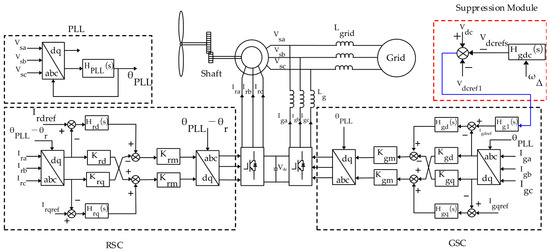
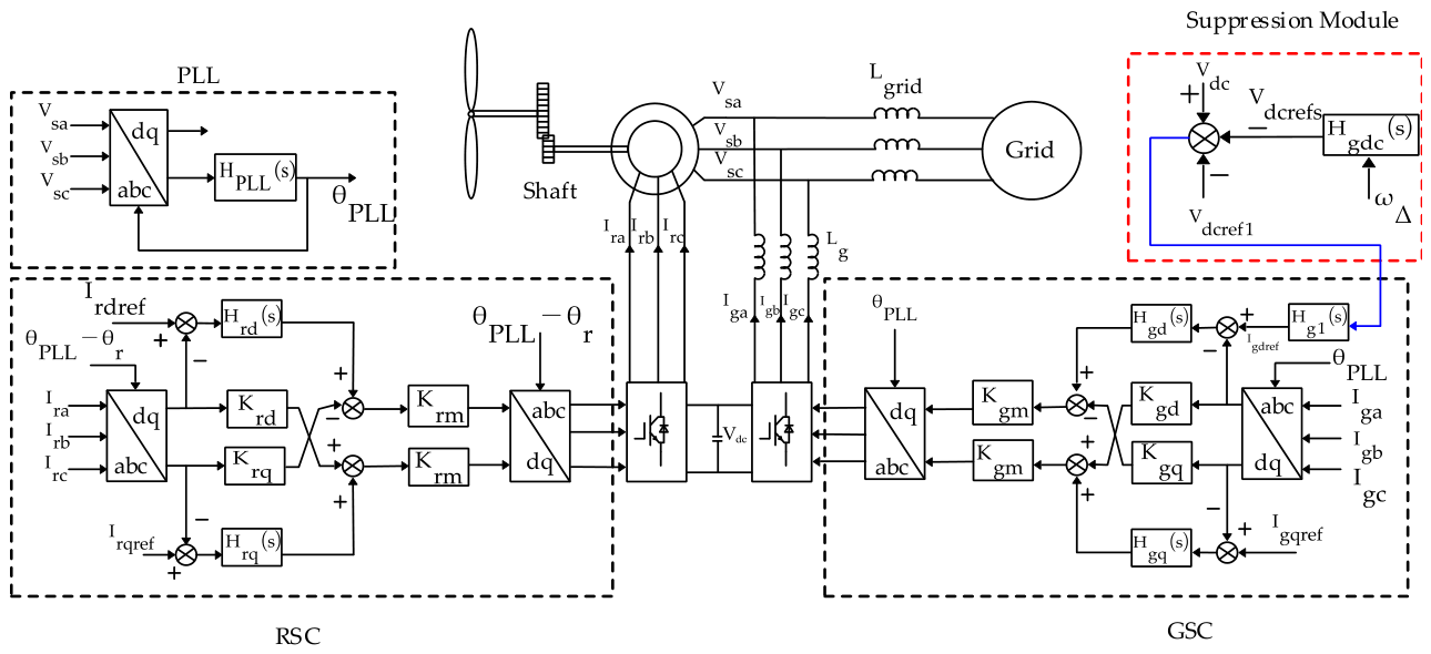
In DFIG systems, the DC-link provides DC voltage to both the RSC and GSC. When the DC-link voltage is subjected to disturbances, corresponding variations occur in the DFIG’s electromagnetic torque and active power output. These variations affect the DFIG’s electromagnetic damping, consequently impacting shaft system stability. The DFIG system configuration is illustrated in Figure 1.
Figure 1.
DFIG system diagram.
The dynamic variations of the DC-link capacitor voltage reflect power changes in both the RSC and GSC, which can be expressed using the following equation:
where is the DC-link capacitance, represents the steady-state DC-link voltage, and and denote the power variations at the GSC and RSC, respectively.
where is the steady-state slip ratio, represents the synchronous angular velocity, and denotes the electromagnetic torque variation.
The power response of the GSC is affected by the dynamic characteristics of its control loop. Under stator flux d-axis orientation, is approximately equal to the grid voltage . By substituting the grid-side voltage into the GSC control loop, the corresponding expression is given as follows:
where and represent the proportional and integral gains, respectively, of the GSC’s outer voltage control loop.
Applying the Laplace transform to Equation (4) and rearranging it, the relationship between the DC-link voltage variation and electromagnetic torque variation can be derived as follows:
At the steady-state operating point, the DC-link voltage increment and electromagnetic torque increment have a fixed expression, with constant magnitude and phase characteristics. By configuring the control loop, the characteristics of the transfer function can be altered to ensure that its associated electrical damping torque is positive. This process enhances shaft damping and mitigates power fluctuations caused by DC-link voltage variations, thereby reducing grid power oscillations and improving both shaft dynamics and grid stability.
To mitigate DC-link dynamics, we propose a DC-link dynamics suppression module , which integrates three functional components: phase compensation, DC blocking, and gain adjustment. The transfer function is formulated as follows:
The proposed DC-link suppression module introduces an additional transfer function into the existing DFIG control structure. The implementation complexity of this module is moderate, primarily reflected in the following aspects:
- (1)
- Precise parameter tuning is required based on the system operating point and natural oscillation frequency;
- (2)
- No additional control hardware is required;
- (3)
- Effective coordination with the existing RSC and GSC control loops can be achieved, avoiding the introduction of adverse interactions.
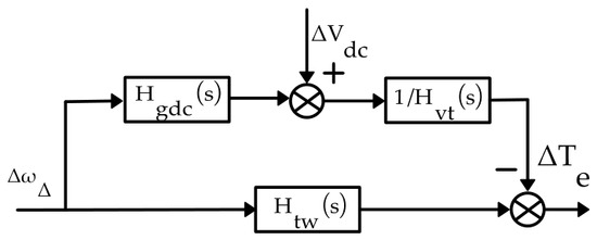
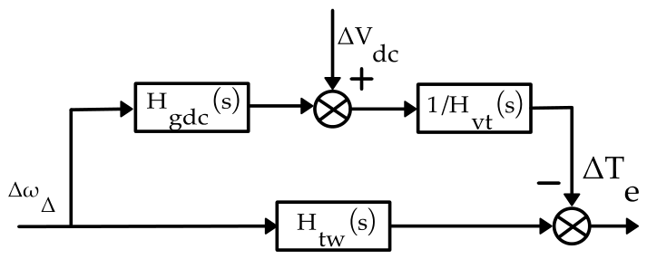
When the DC-link dynamics suppression module is incorporated, the relationship between the DFIG’s electromagnetic torque variation and rotational speed difference variation (as illustrated in Figure 2) can be expressed as follows [25].
where is the turbine angular velocity and is the rotor angular velocity.
Figure 2.
Block diagram of DFIG shaft transfer function under DC dynamics suppression.
When the DFIG operates in maximum power point tracking (MPPT) control mode and disregards the inherent DC-link dynamics, based on mechanical and aerodynamic linearization, the transfer function is expressed as follows:
where is a constant related to the inherent properties of the wind turbine and the gear ratio. The expression under constant power mode is as follows:
where and are the inertia time constants of the wind turbine and DFIG rotor, and are the proportional and integral gains of the rotor-side PI controller, P is the rated power, and .
From Equation (7), the electromagnetic torque variation is decomposed into a damping torque component (in phase with the speed difference variation ) and a synchronous torque component (in phase with the torsional angle variation ):
where is the electromagnetic damping torque coefficient and is the electrical synchronous torque coefficient.
The dynamic equations of the two-mass shaft system are expressed in incremental form as follows:
where is the damping coefficient of the wind turbine and rotor shaft, is the stiffness coefficient, and is the input mechanical torque.
From Equation (12), the DFIG shaft oscillation damping coefficient is obtained as follows:
where is the natural oscillation frequency of the DFIG shaft system ( rad/s).
From Equation (13), the influence of on the DFIG shaft oscillation damping coefficient, the phase relationship between and , and shaft stability is summarized in Table 1. In this paper, a negative electrical damping coefficient corresponds to positive damping, whereas a positive corresponds to negative damping.
Table 1.
Impact of on DFIG shaft stability.
3. Frequency-Coupled Oscillation Modeling of DFIG Considering DC-Link Dynamics
3.1. Analytical Model of DFIG Under DC-Link Dynamics
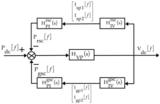
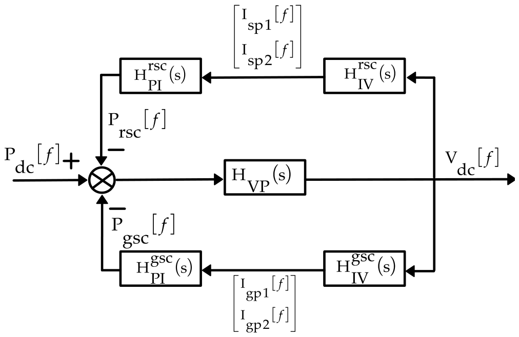
As shown in Figure 1, DC-link voltage fluctuations propagate through both the outer-loop and inner-loop voltage control channels to affect the output voltage of the GSC while simultaneously influencing the RSC output voltage via the rotor-side control loop. The detailed small-signal transfer path of DC dynamics is shown in Figure 3.
Figure 3.
Signal transmission paths of DC-link dynamics in DFIG systems.
From Equation (1), the frequency-domain transfer function between DC power and DC-link voltage can be derived as follows:
where , is the reference voltage of the DC-link, is the input reference voltage of the DC-link (a constant value), and is the compensation voltage of the DC-link. When the frequency of the DC-link voltage disturbance component is , the d-axis current reference for the GSC at this frequency can be obtained as follows:
where is the DC-link voltage outer-loop controller.
Substituting the dq-axis current components of the GSC (the frequency-domain expressions of GSC’s dq-axis currents under phase-locked loop are derived in Appendix A, Equations (A1)–(A6) into the grid-side control loop yields the following:
where is the inner-loop d-axis controller of the GSC, which is expressed as , and is the inner-loop q-axis controller of the GSC, which is expressed as , and are the dq-axis decoupling coefficients of the GSC, and and are the frequency-domain forms of the GSC dq-axis currents.
Applying the inverse Park transform to Equation (16) gives , while the GSC output voltage is determined by both the modulation coefficient and the DC-link voltage [11,12]:
where is the modulation coefficient of the GSC, and is the phase-a voltage of the GSC in the time domain.
Combined with the dynamic characteristics of the GSC filter inductance , substituting Equations (15) and (16) into Equation (17),the relationship between the GSC current and DC-link voltage in the frequency domain is obtained as follows (this equation reveals that the GSC current perturbation is generated by the DC-link voltage through the combined effects of the inner and outer loop controllers, the decoupling terms, and the filter inductor. Furthermore, coupling exists between the positive and negative frequency components):
where , represents the fundamental-frequency voltage of the GSC, is the GSC current in the frequency domain, which is expressed as , and * denotes the complex conjugate.
Similarly, the relationship between the RSC current and DC-link voltage in the frequency domain can be derived as follows:
where is the stator current in the frequency domain, which is expressed as , , , , and are given as follows:
In Equations (19)–(21), and are the inner-loop controllers of the RSC (subscripts d and q denote the d-axis and q-axis components of the corresponding variables, respectively), can be expressed as , can be expressed as , is the fundamental-frequency voltage of the RSC; and are the decoupling coefficients of the RSC, is the modulation coefficient, represents the resistance (subscripts s and r correspond to the stator and rotor components of the DFIG, respectively), is the inductance, is the mutual inductance, and is the turns ratio. The positive and negative sequence steady-state slip ratios and in the frequency domain are given in the Appendix A, Equation (A11).
The DC-link power of the DFIG is related to both the GSC and RSC. From (1), the DC-link power can be rewritten as follows:
where subscripts a, b, and c denote the three-phase components, i and v represent the time-domain current and voltage, and subscripts r and g denote the RSC and GSC, respectively. Transforming (22) into the frequency domain yields the following:
where , , , and are the fundamental-frequency components of the grid voltage, rotor voltage, GSC output current, and rotor current. The subscript p1 denotes the frequency component at , and the subscript p2 denotes the frequency component at .
Substituting the frequency-domain equations of the DFIG’s rotor and stator voltages (Appendix A, Equations (A7)–(A11)) into (23) gives the following:
Specifically, the functional relationship between DC-link power and DC-link voltage (), the functional relationship between DC-link power and GSC current (), and the functional relationship between DC-link power and RSC current () are detailed in Equations (A18)–(A20) in Appendix A.
3.2. Frequency-Coupled Analytical Model of DFIG Under DC-Link Dynamics
Based on the signal transmission paths of DFIG DC-link dynamics, the frequency-coupled analytical model of the DFIG grid connection port under DC-link dynamics can be derived as follows:
When DC-link dynamics are neglected, the frequency-coupled impedances of the RSC and GSC in the DFIG remain decoupled. Therefore, when considering the effects of DC-link dynamics, the overall frequency-coupled analytical model of the DFIG system can be obtained by connecting in parallel the RSC and GSC frequency-coupled impedance models (Appendix A, Equations (A12)–(A17)) with the frequency-coupled analytical model of the DFIG grid connection port under DC-link dynamics:
3.3. Frequency-Coupled Analytical Model of DFIG Grid Integration Considering DC-Link Dynamics
During DFIG grid integration, DC-link dynamics also affect the grid-connected system and induce corresponding frequency responses. When treating the three-phase balanced grid as a feedback loop, the ratio of the DFIG terminal voltage disturbance to current disturbance at frequency points and constitutes the grid-connected frequency-coupled impedance. From Equations (27) and (28), the grid-connected impedance is derived as follows [26,27]:
where the superscripts 11, 12, 21, and 22 denote the elements of the matrix, represents the grid impedance, and and are the grid-connected impedances of the DFIG at frequency points and .
3.4. Assumptions and Limitations
The proposed model and analysis are based on the following assumptions and constraints:
- (1)
- Switching-cycle averaging assumption: All converters (RSC and GSC) are modeled using the switching-cycle averaged model, which neglects high-frequency switching harmonics at 10 kHz and above. This assumption is fully valid for analyzing the low-frequency dynamics of interest in this paper, such as shaft system oscillations and subsynchronous oscillations.
- (2)
- Balanced three-phase grid assumption: The grid is assumed to be a balanced three-phase system, and all analyses are conducted in the synchronous dq reference frame. Unbalanced grid conditions are beyond the scope of this study.
- (3)
- Current limiting, PWM saturation, and anti-windup mechanisms: The model assumes ideal power switches without conduction or switching losses, and temporarily omits current limiting, PWM saturation, and anti-windup mechanisms. These nonlinear effects are only activated under large disturbances. Since this study focuses on small-signal perturbation conditions, their omission does not compromise the accuracy of the stability analysis.
- (4)
- Small-signal perturbation amplitude: All analyses and simulations are based on the small-signal linearization assumption, with the perturbation amplitude not exceeding 5% of the rated value. Large-disturbance conditions require nonlinear analysis methods, which may lead to deviations from the predictions made in this paper.
4. Impact of DC-Link Dynamics Suppression on DFIG Shaft Oscillation Damping and Grid-Connected Impedance
In addition to influencing the DFIG’s electromagnetic torque and active power output (thereby altering the electrical damping torque coefficient associated with shaft oscillations), DC-link dynamics also impact grid stability through the control loops of both the RSC and GSC, ultimately modifying the DFIG unit’s grid connection behavior.
4.1. Influence of DC-Link Dynamics Suppression on DFIG Shaft System
Based on the established DFIG shaft model, when rotor frequencies are 0.8 pu, 0.9 pu, 1.0 pu, 1.2 pu, 1.3 pu, and 1.4 pu, the phase angle of at the DFIG’s natural oscillation frequency ( = 9.14 rad/s) is calculated. The results indicate an average required phase compensation of −150°, yielding parameter values of = −0.408, and = 0.408, with the DC-blocking constant set to = 10 and gain = 1.6. The implementation and stability analysis of the suppression module in the discrete domain are presented in Appendix C.
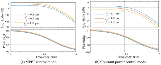
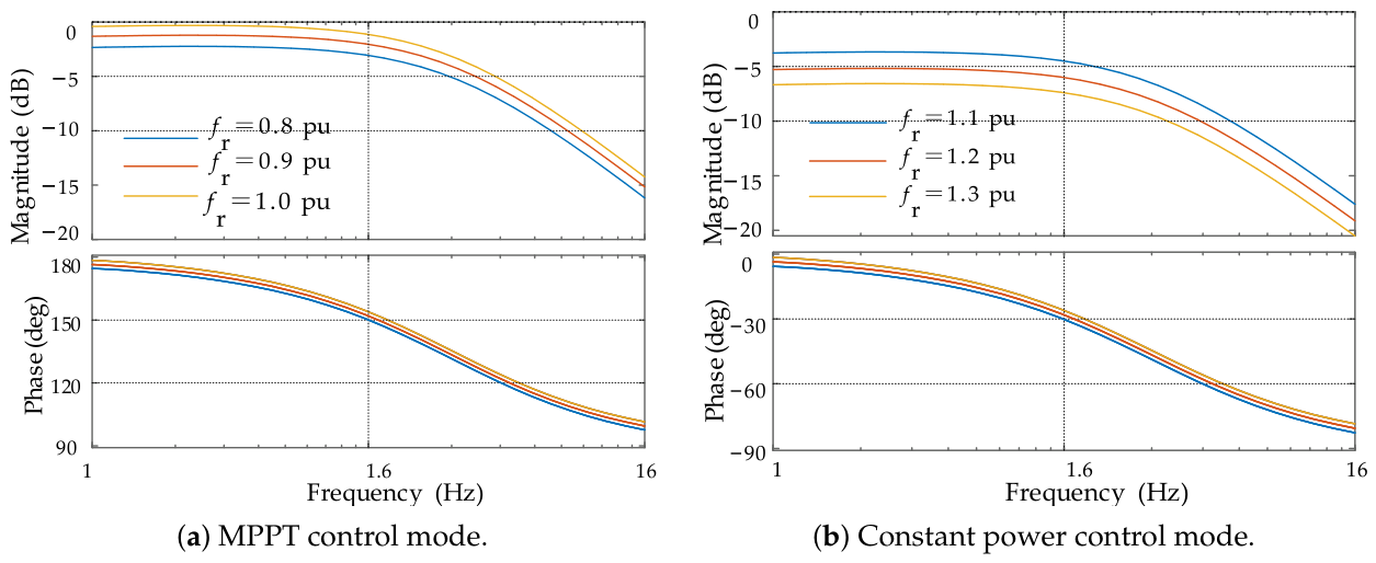
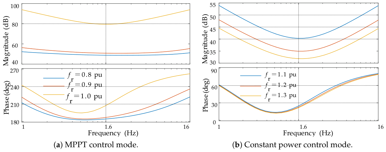
Using the DFIG parameters listed in Table 2 and a grid inductance of 0.82 mH, the Bode plots of are derived from (7) for rotor frequencies of 0.8 pu, 0.9 pu, 1.0 pu, 1.2 pu, 1.3 pu, and 1.4 pu. Figure 4 presents the results without DC-link dynamics suppression, while Figure 5 presents the effects with suppression implemented (Frequency (Hz) refers to the disturbance frequency).
Table 2.
2MW DFIG parameters.
Figure 4.
Bode diagrams of at different wind speeds without the DC-link dynamics suppression module.
Figure 5.
Bode diagrams of at different wind speeds with the DC-link dynamics suppression module.
- (1)
- In MPPT control mode without the DC-link dynamics suppression module, the phase angle range of is approximately 100–180°, with electrical damping coefficients of −0.6524, −0.7340, and −0.8147 at different rotor frequencies. With the suppression module, the phase angle range shifts to 180–260° and becomes −0.6728, −0.8452, and −2.7263. All points lie in the second and third quadrants of the phasor diagram where , indicating positive damping for the shaft system. As rotor frequency increases, increases ( becomes more negative), enhancing shaft stability.
- (2)
- In constant power control mode without suppression, the phase angle range is −90–0°, with values of 0.5532, 0.4648, and 0.3961. With suppression, the range changes to 10–80°, and becomes 4.7579, 2.6063, and 1.8416. All points are in the first and fourth quadrants where , providing negative damping that weakens shaft stability under disturbances. Under constant power control, the RSC regulates the active power reference to a fixed value rather than tracking the MPPT curve. Consequently, the electromagnetic torque becomes insensitive to the angular velocity deviation . The shaft system control adjusts the rotor current to actively counteract the speed deviation, which weakens the electromechanical coupling effect. In engineering applications, when operating in constant power mode, the wind turbine activates pitch angle control. This control mechanism essentially provides strong mechanical damping for shaft torsional oscillations. Consequently, the negative impact of the suppression module (if kept active) on shaft stability is significantly mitigated by the pitch control.
- (3)
- For the DFIG in MPPT mode, the suppression module significantly reduces (i.e., makes it more negative), thereby increasing positive damping from the electrical system and improving shaft stability.
4.2. Impact of DC-Link Dynamics Without the Suppression Module on DFIG Grid Impedance
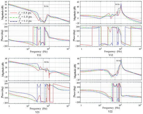
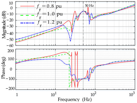
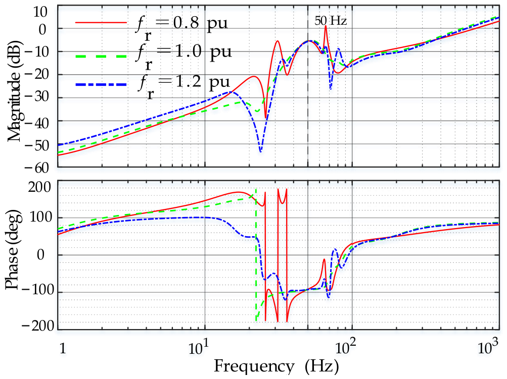
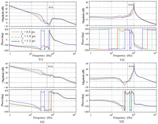
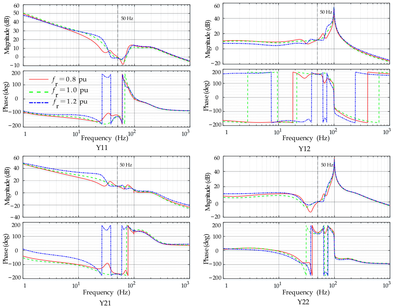
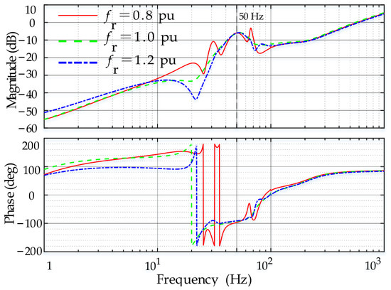
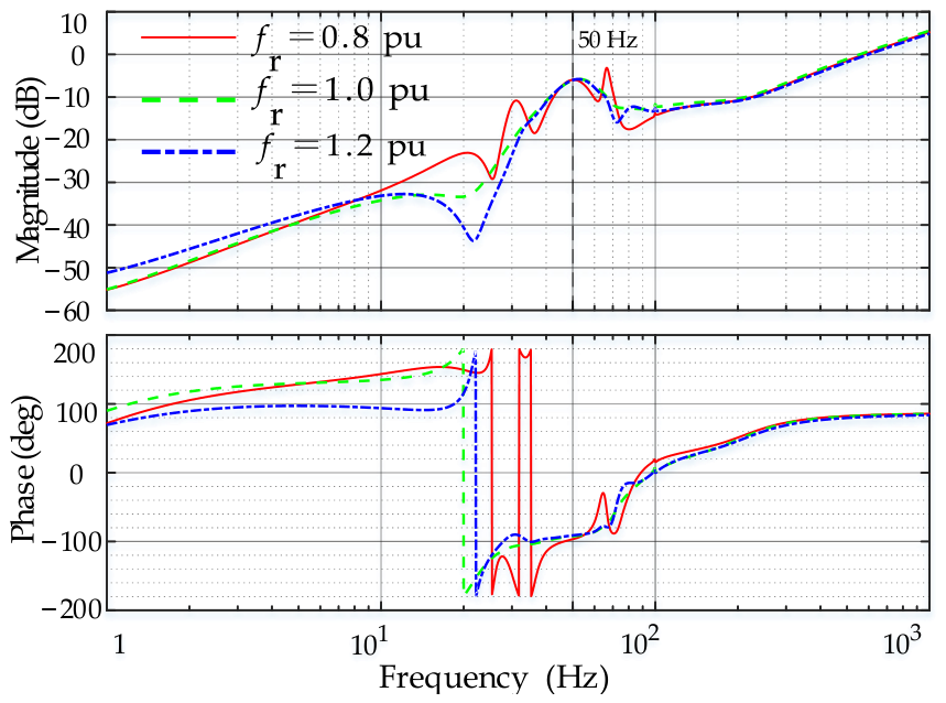
When the DC-link dynamics suppression module is disabled (parameters unchanged), the frequency coupling characteristics of DFIG considering DC-link dynamics (27) at rotor frequencies of 0.8 pu, 1.0 pu, and 1.2 pu are shown in Figure 6. The grid-impedance characteristics (29) are presented in Figure 7.
Figure 6.
Frequency coupling characteristics of DFIG with DC-link dynamics (without the suppression module).
Figure 7.
Grid-impedance characteristics of DFIG with DC-link dynamics (without the suppression module).
In Figure 6, it can be observed that, near the 50 Hz fundamental frequency, the amplitude ratios between diagonal components , and off-diagonal components , approach unity, indicating significant frequency coupling. As rotor frequency increases, frequency coupling characteristics change substantially below 50 Hz but remain relatively stable above 50 Hz.
In Figure 7, it can be observed that the grid impedance exhibits positive damping when and negative damping when . The zero-crossing frequencies of (where ) are 2 Hz, 1.5 Hz, and 2.5 Hz at increasing rotor frequencies. Under MPPT control, this finding indicates reduced negative damping; under constant power control, it implies increased negative damping. At different rotor frequencies, DFIG grid impedance has a greater impact below 50 Hz and less influence above 50 Hz.
According to the generalized Nyquist stability criterion [26,27],
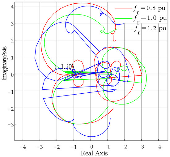
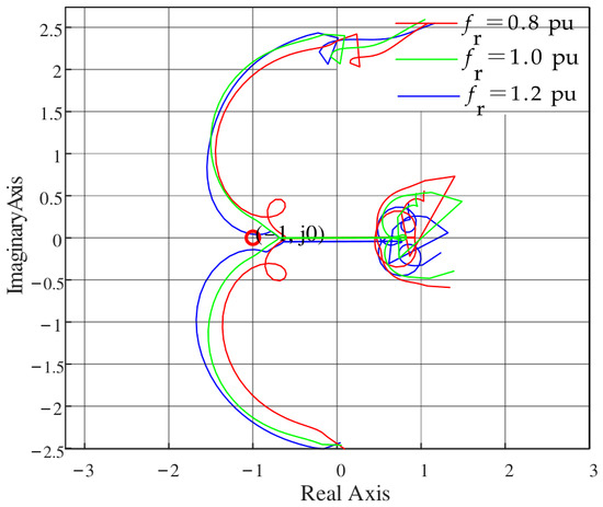
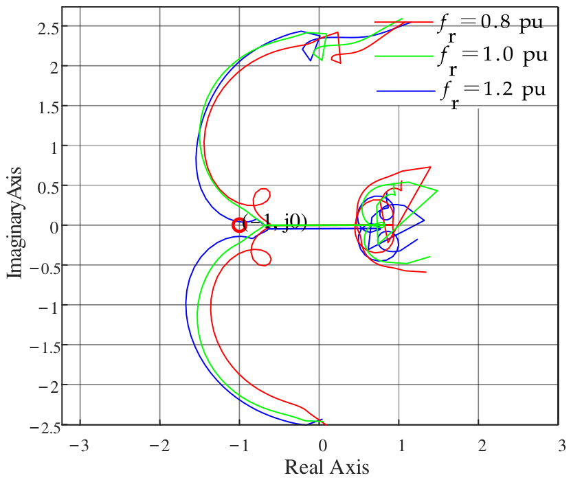
The Nyquist plot of the DFIG, with DC-link dynamics included and the DC-link dynamics suppression module disabled, is shown in Figure 8. It is observed that all Nyquist curves encircle the (−1, j0) point, with intersection frequencies at 18 Hz and 82 Hz, 20 Hz and 80 Hz, and 17 Hz and 83 Hz, respectively. This finding indicates oscillatory instability during grid synchronization, with oscillation frequencies of 18/82 Hz, 20/80 Hz, and 17/83 Hz at the grid connection point.
Figure 8.
Nyquist plot of DFIG with DC-link dynamics (without a suppression module).
Based on the loop gain matrix , the gain margin (GM) and phase margin (PM) of the system are calculated. Without the suppression module, when the rotor frequency is 0.8 pu, dB and ; at a rotor frequency of 1.0 pu, dB and ; and at 1.2 pu, dB and . The GM of the system is less than 0, and the PM is relatively small, indicating that the system may experience oscillations due to multi-modal coupling or nonlinear factors.
4.3. Impact of the DC-Link Dynamics Suppression Module on Grid Impedance
With the DC-link dynamics suppression module activated (parameters unchanged), the frequency coupling characteristics (27) and grid-impedance characteristics (29) of the DFIG at rotor frequencies of 0.8 pu, 1.0 pu, and 1.2 pu are shown in Figure 9 and Figure 10.
Figure 9.
Frequency coupling characteristics of the DFIG under DC-link dynamics (with the suppression module).
Figure 10.
Grid-impedance characteristics of the DFIG under DC-link dynamics (with the suppression module).
In Figure 9, it can be observed that with the DC-link dynamics suppression module activated, the amplitude fluctuations of , , , are significantly reduced. As the rotor frequency increases, the frequencies where in Figure 10 (DFIG grid impedance with suppression) are 1.4 Hz, 1.0 Hz, and 2.0 Hz, indicating a moderate reduction in the degree of negative damping in the grid impedance after implementing the suppression module.
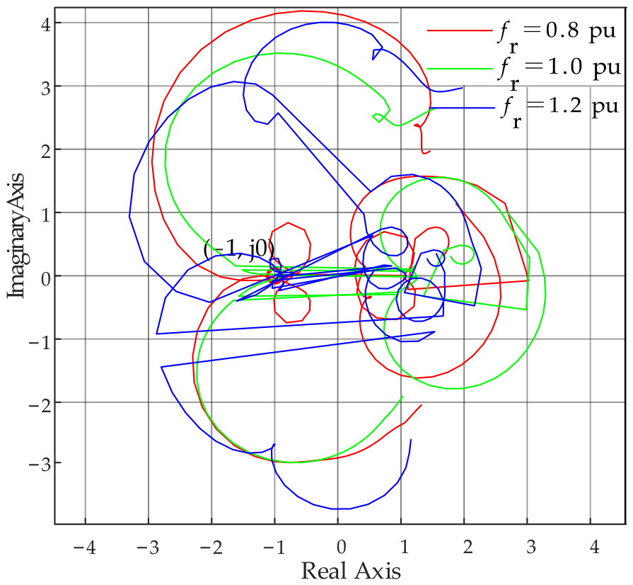
The Nyquist plot of the DFIG with the DC-link dynamics suppression module activated is shown in Figure 11. As observed in Figure 11, neither Nyquist curve of the interconnected system encircles the (−1, j0) point, demonstrating that the system satisfies small-signal stability requirements.
Figure 11.
Nyquist plot of the DFIG under DC-link dynamics (with the suppression module).
After incorporating the suppression module, the GM and PM of the system are calculated. At a rotor frequency of 0.8 pu, dB and ; at 1.0 pu, dB and ; and at 1.2 pu, dB and . Compared to the case without the suppression module, the stability margins have been significantly improved.
5. Simulation Verification
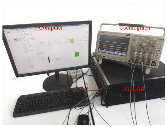
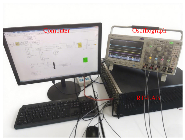
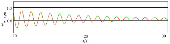
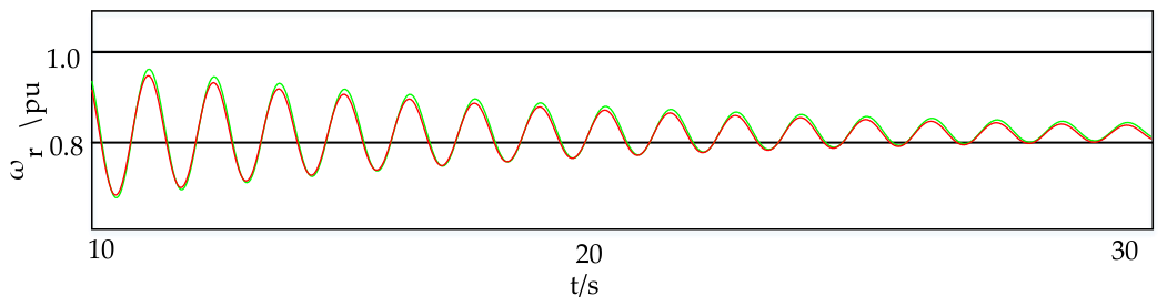
A 2 MW DFIG simulation model is established on the software-in-the-loop real-time simulation platform shown in Figure 12 (which includes a computer, an oscilloscope, and RT-LAB); the simulation time step is set to 1 µs. The system sampling time is 100 µs. In the simulation experiments, a step disturbance with an amplitude of 5% of the rated DC voltage (60 V) is superimposed on the DC bus voltage reference, and this identical disturbance is applied across all simulation experimental cases. Based on the DFIG wind power system parameters listed in Table 2 (grid inductance: 0.82 mH, rotor frequency: 0.8 pu), the results presented in Figure 13 demonstrate the impact of the DC-link dynamics suppression module on the DFIG rotor speed.
Figure 12.
Real-time simulation platform.
Figure 13.
Rotor speed waveforms under DC-link voltage fluctuations. Red—with the suppression module; green—without the suppression module.
As seen in Figure 13, with the DC-link dynamics suppression module activated, the rotor speed fluctuations of the DFIG are significantly reduced, and shaft oscillations diminish. These results align with the shaft stability analysis presented in Section 4.1.
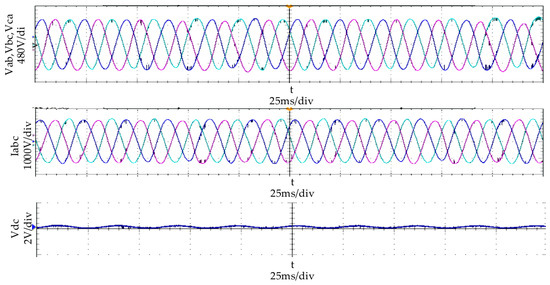
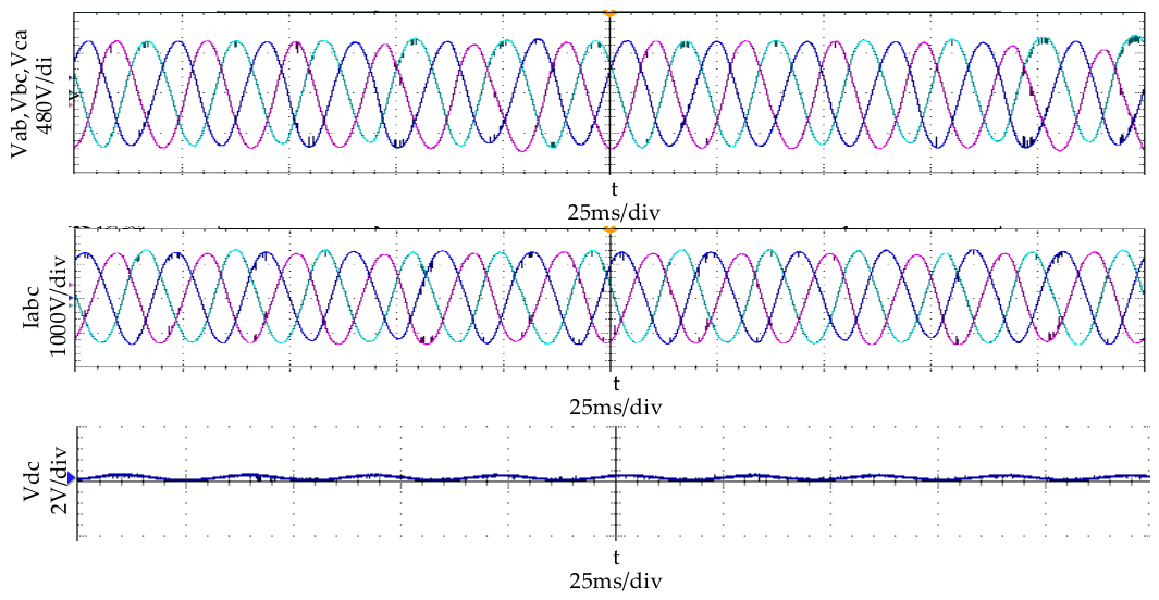
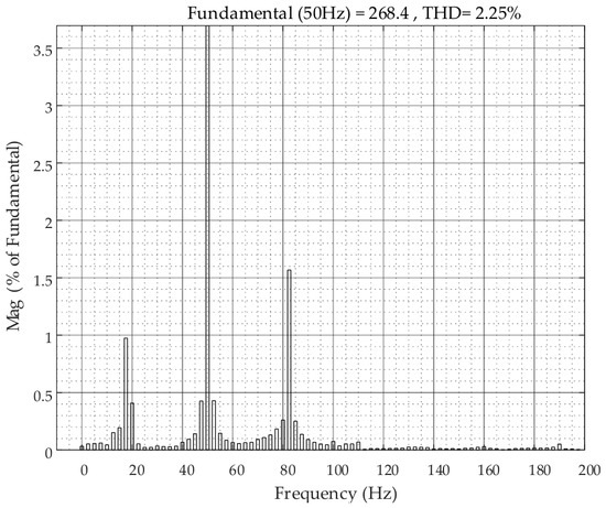
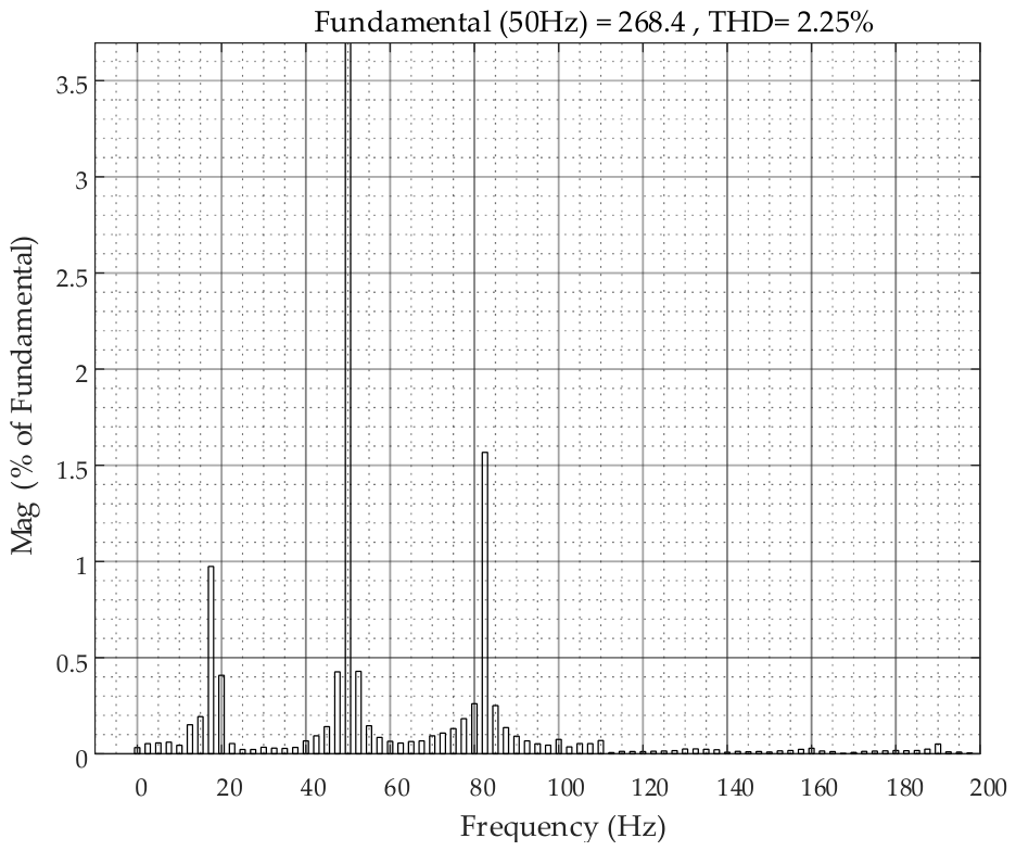
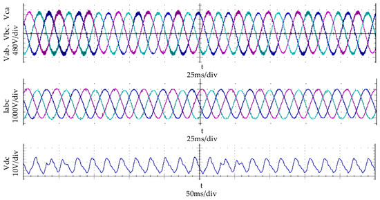
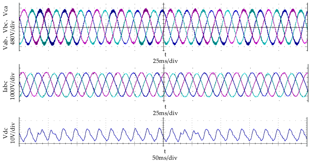
At a rotor frequency of 0.8 pu, after the DFIG system with the suppression module reaches steady-state operation, the following waveforms at the grid connection point are captured and shown in Figure 14: the three-phase voltage at the grid connection point (, , ), three-phase currents (), and DC-link voltage (). The corresponding FFT analysis results are presented in Figure 15.
Figure 14.
Grid-connected waveforms of the DFIG (with the suppression module).
Figure 15.
FFT analysis of the three-phase currents at the grid connection point (with the suppression module).
The FFT analysis results presented in Figure 15 reveal minor harmonic components in the grid connection point current, signifying a stable state. This finding confirms that the DC dynamics suppression link effectively mitigates frequency coupling oscillations.
At a rotor frequency of 0.8 pu, the following waveforms at the grid connection point of the DFIG machine-side system under steady-state operation without the DC-link dynamics suppression module are shown in Figure 16. The corresponding FFT analysis results are presented in Figure 17.
Figure 16.
Grid-connected waveforms of the DFIG (without the suppression module).
Figure 17.
FFT analysis of the three-phase currents at the grid connection point (without the suppression module).
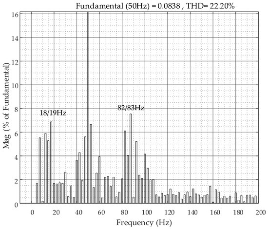
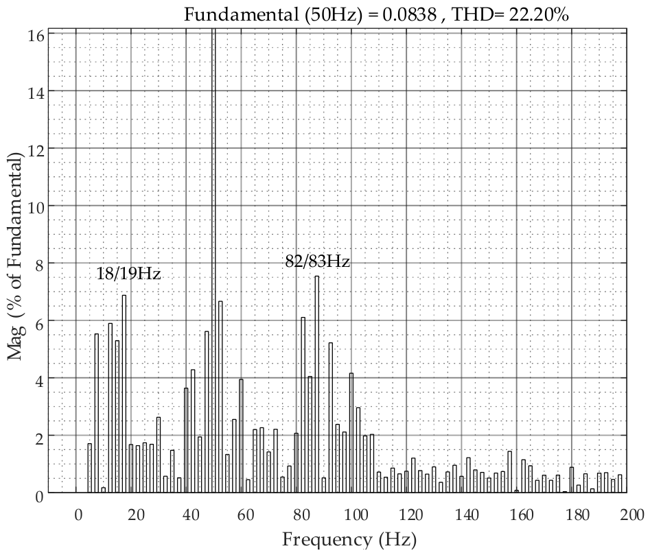
In Figure 17, the FFT analysis results of the three-phase currents at the grid connection point (without the suppression module) reveal distinct harmonic components at approximately 18/19 Hz and 82/83 Hz, alongside the fundamental 50 Hz component. These frequencies correspond to sub-synchronous and super-synchronous oscillations, which are symmetrically distributed around the fundamental frequency. The presence of these components leads to a high total harmonic distortion (THD) level (the value is 19.95% higher than the THD obtained with the suppression module), indicating severe distortion of the grid current. This distortion is a direct manifestation of the frequency-coupling effect induced by DC-link dynamics. The high THD confirms that the DFIG system without suppression is prone to oscillatory instability, which can compromise power quality and grid reliability. This phenomenon aligns with the generalized Nyquist criterion results presented in Figure 8. The encirclement of the critical point (−1, j0) confirms system instability at the 18/82 Hz band.
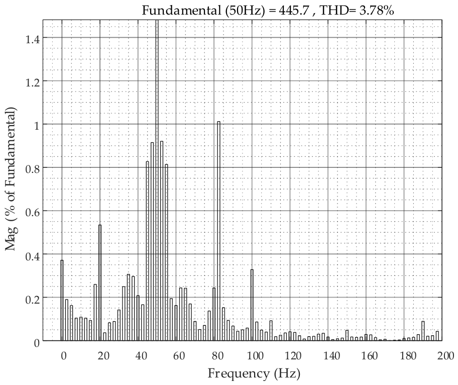
To demonstrate the effectiveness of the DC-link dynamics suppression module, the following observations can be made from Figure A2 (Appendix B): when the rotor frequency is 1.2 pu, the FFT analysis results show that after applying the DC dynamics suppression module, the harmonic component of the grid-connected current increases by 1.53% compared to the case at a rotor frequency of 0.8 pu. However, the system remains stable, which is consistent with the Nyquist analysis results presented in Figure 11. Furthermore, as shown in Figure A4 (Appendix B), at a rotor frequency of 0.8 pu and a grid inductance of 1.64 mH, the FFT analysis results indicate that after applying the suppression module, the harmonic component of the grid-connected current increases by 3.79% compared to the case at a rotor frequency of 0.8 pu, and the system still maintains satisfactory stability.
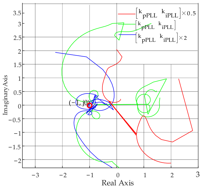
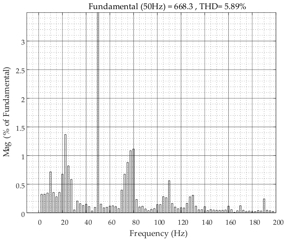
When the PLL control parameter is reduced to 0.5 times its nominal value (bandwidth: 21 Hz), the Nyquist curve in Figure A5 does not encircle the (−1, j0) point. The system achieves a GM of 10.5 dB and a PM of , both of which are improved over the nominal condition, confirming that the small-signal stability requirements are satisfied. Under the same parameter setting, Figure A7 shows that the harmonic content of the grid-connected current is 5.89%, indicating stable system operation.
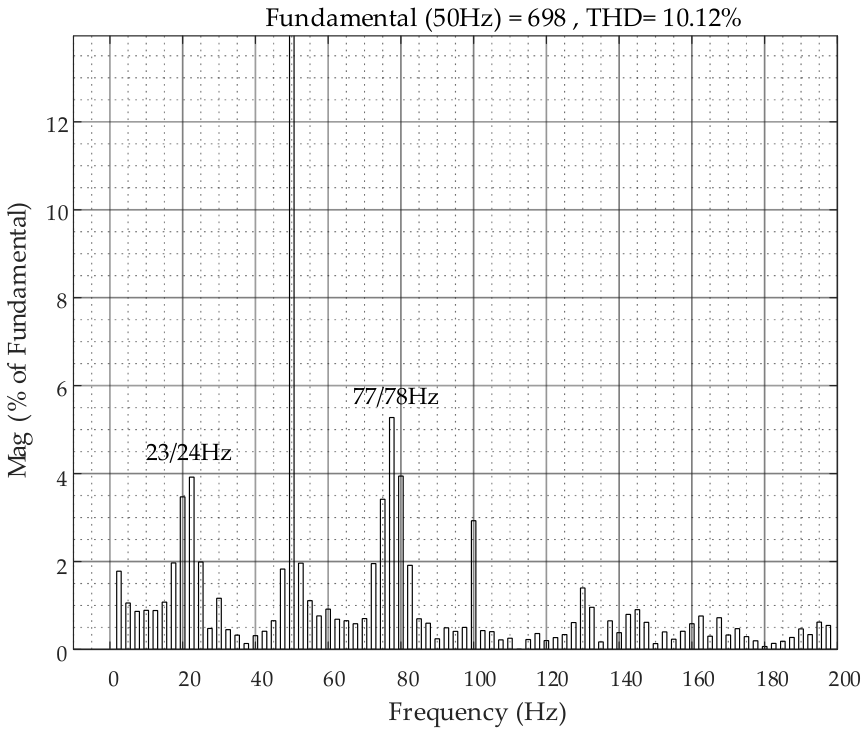
Conversely, when the parameter is increased to 2 times the nominal value (bandwidth: 82 Hz), the Nyquist curve in Figure A5 encircles the (−1, j0) point, with a unit-circle crossing at 23/77 Hz. The GM drops to dB and the PM to , which may induce system oscillations. Furthermore, the harmonic content rises to 10.12% (an increase of 7.87% relative to the nominal condition), and the FFT analysis in Figure A9 detects the 23/77 Hz component. Therefore, increasing the PLL control bandwidth adversely affects the grid-connected operation of the DFIG.
6. Conclusions
Based on our investigation into the mechanisms of shaft oscillation and grid-connected frequency coupling in DFIGs under DC-link dynamics, we draw the following conclusions:
- (1)
- DC-link voltage fluctuations affect electromagnetic torque through interactions between the RSC and GSC, altering shaft dynamic characteristics. Simultaneously, they compromise system stability by propagating through control loops to the grid-connected system.
- (2)
- The DC-link dynamics suppression module proposed in this paper can significantly enhance electrical positive damping in MPPT mode. By optimizing the phase relationship of the electromagnetic torque response, this module effectively mitigates speed fluctuations and improves shaft stability. However, in constant power mode, its stabilizing effect is limited and may even introduce negative damping.
- (3)
- Frequency-domain modeling and the generalized Nyquist criterion demonstrate that the suppression module reduces the negative damping region of grid impedance, avoids encirclement of the critical point (−1, j0) in Nyquist plots, eliminates sub/super-synchronous oscillations (e.g., 18/82 Hz), and enhances grid connection robustness. Simulation results validate model accuracy and confirm the engineering applicability of the proposed suppression strategy.
Author Contributions
Methodology, Y.L.; validation, Z.W. and Y.L.; investigation, Z.W.; data curation, Z.W.; writing—original draft, Z.W.; writing—review and editing, Z.W. All authors have read and agreed to the published version of the manuscript.
Funding
This research received no external funding.
Data Availability Statement
The original contributions presented in this study are included in the article. Further inquiries can be directed to the corresponding author.
Conflicts of Interest
The authors declare no conflicts of interest.
Appendix A
Based on the small-signal modeling approach [11,12], the frequency-domain expressions for the voltage and current of the DFIG’s GSC are given as follows:
where , and other components can be derived analogously.
Applying the Park transformation to (A1) and (A2), the frequency-domain expression of the PLL is obtained through the harmonic linearization method:
where
Based on the frequency-domain expression of the grid-side PLL in the DFIG, the current expressions in the dq-frame for the GSC can be derived as follows:
By performing a frequency transformation on the DFIG voltage and flux equations in the dq-frame, the rotor voltage expressions at frequencies and are, respectively, given as follows:
where
Appendix B
At a rotor frequency of 1.2 pu, after the DFIG system with the suppression module reaches steady-state operation, the waveforms at the grid connection point shown in Figure A1 are captured (the three-phase voltage at the grid connection point (, , ), three-phase currents (), and DC-link voltage ()). The corresponding FFT analysis results are presented in Figure A2.
At a rotor frequency of 0.8 pu (grid inductance: 1.64 mH), after the DFIG system with the suppression module reaches steady-state operation, the following waveforms at the grid connection point are captured, as shown in Figure A3: the three-phase voltage at the grid connection point (, , ), three-phase currents (), and DC-link voltage (). The corresponding FFT analysis results are presented in Figure A4.
Figure A1.
Grid-connected waveforms of the DFIG (with the suppression module, rotor frequency is 1.2 pu).
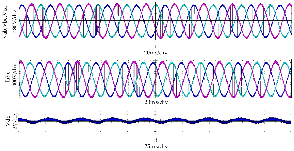
Figure A2.
FFT analysis of the three-phase currents at the grid connection point (with the suppression module, rotor frequency is 1.2 pu).
Using the PLL control parameters in Table 2, adjusting to 0.5 and 2 times their original values changes the corresponding PLL control bandwidth to 21 Hz and 82 Hz from 40 Hz. Keeping the rotor frequency at 0.8 pu and the remaining parameters unchanged, the Nyquist analysis with the DC-link suppression module included is presented in Figure A5.
Figure A3.
Grid-connected waveforms of the DFIG (with the suppression module, grid inductance: 1.64 mH).
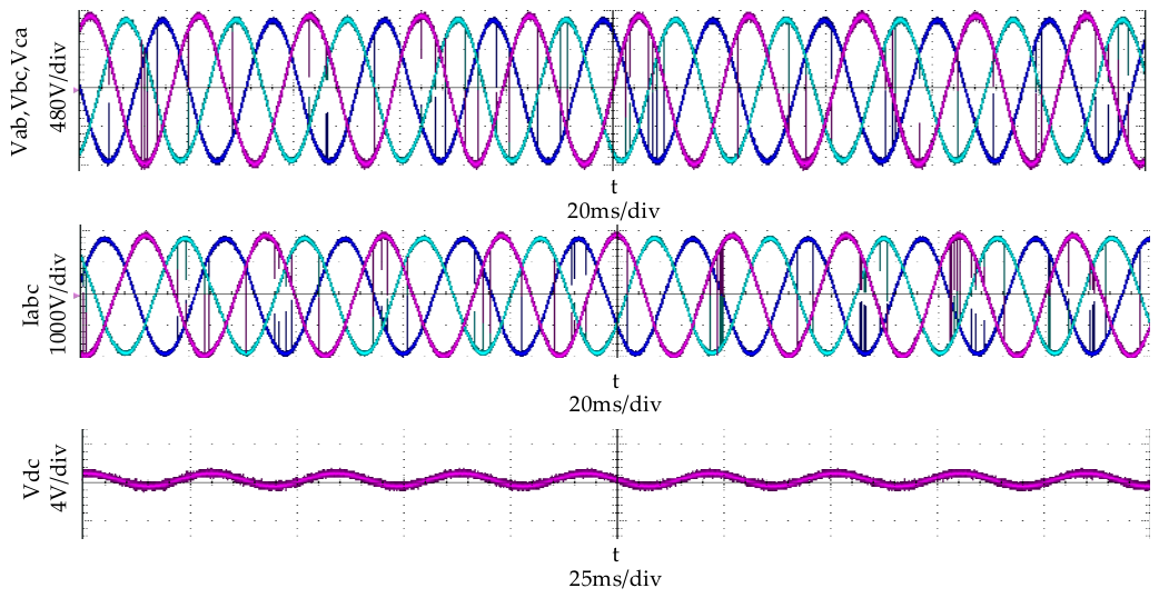
Figure A4.
FFT analysis of the three-phase currents at the grid connection point (with the suppression module, grid inductance: 1.64 mH).
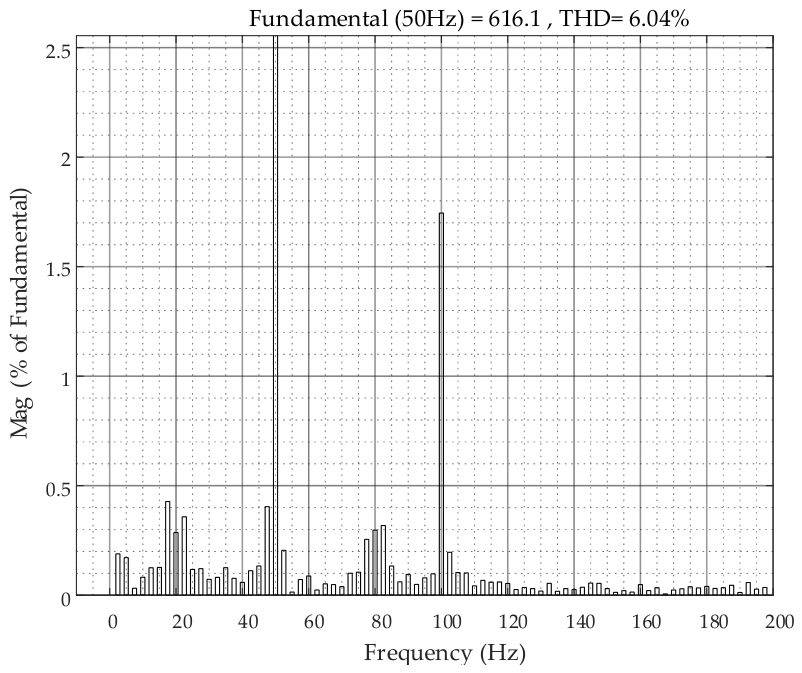
Figure A5.
Nyquist plot of the DFIG considering the PLL parameters (with the suppression module).
At a rotor frequency of 0.8 pu (), after the DFIG system with the suppression module reaches steady-state operation, the following waveforms at the grid connection point are captured and shown in Figure A6: the three-phase voltage at the grid connection point (, , ), three-phase currents (), and DC-link voltage (). The corresponding FFT analysis results are presented in Figure A7.
Figure A6.
Grid-connected waveforms of the DFIG under (with the suppression module).
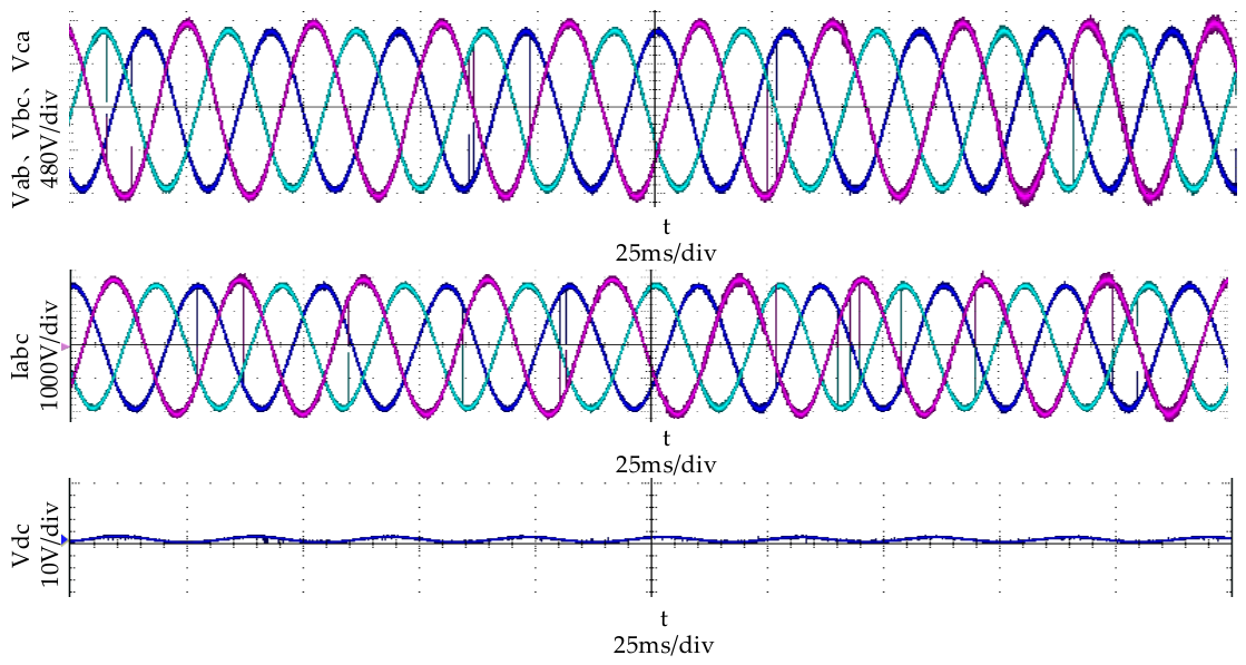
Figure A7.
FFT analysis of the three-phase currents at the grid connection point (with the suppression module, ).
At a rotor frequency of 0.8 pu (), after the DFIG system with the suppression module reaches steady-state operation, the following waveforms at the grid connection point are captured and shown in Figure A8: the three-phase voltage at the grid connection point (, , ), three-phase currents (), and DC-link voltage (). The corresponding FFT analysis results are presented in Figure A9.
Figure A8.
Grid-connected waveforms of the DFIG under (with the suppression module).
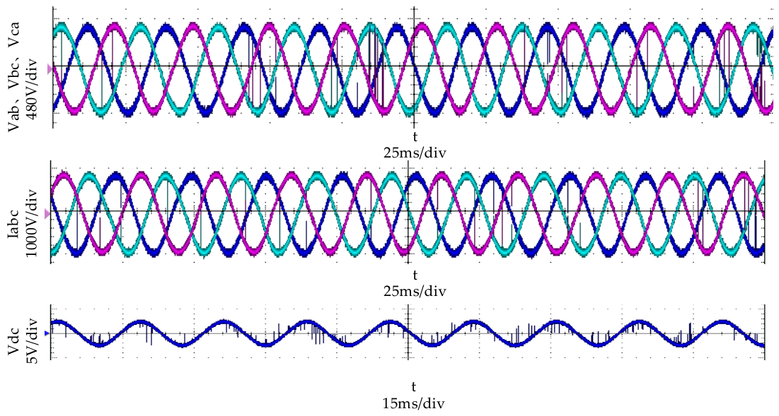
Figure A9.
FFT analysis of the three-phase currents at the grid connection point (with the suppression module, ).
Appendix C
With a sampling time of µs, the DC-link suppression module in this paper is discretized using the bilinear transformation. The transformation formula is given by the following:
This yields the zero-pole form:
From Equation (A24), the discrete-domain poles are and . Since both lie within the unit circle, the controller itself is asymptotically stable. The discrete-domain zeros are and 1. The zero at is located in the right half-plane (RHP), introducing a non-minimum phase characteristic. However, since the controller bandwidth is primarily in the low-frequency range, this characteristic will not affect the high-frequency dynamic performance. The zero at 1 is introduced to achieve DC blocking, ensuring that the suppression module does not compromise the steady-state regulation accuracy of the DC-link voltage.
In summary, the condition introduces an RHP zero. This phenomenon is acceptable and does not compromise system stability. The compensator is causal and stable and can be readily implemented in the discrete-time domain.
References
- Fu, Y.; Ren, Z.; Wei, S.; Xu, Y.; Li, F. Using Flux Linkage Difference Vector in Early Inter-Turn Short Circuit Detection for the Windings of Offshore Wind DFIGs. IEEE Trans. Energy Convers. 2021, 36, 3007–3015. [Google Scholar] [CrossRef] [Scilit]
- Han, J.; Liu, C.; Liu, Z.; Jatskevich, J.; Shang, L.; Dong, X. Dynamic-Tracking Damping Controller for DFIG-Based Wind Farms to Mitigate Sub-Synchronous Control Interactions. IEEE Trans. Power Electron. 2025, 40, 2248–2258. [Google Scholar]
- Zhang, X.; Liu, H.; Cao, Y.; Fu, Y.; Huang, Y.; Li, Y. Virtual Shaft Control of Virtual Synchronous Generator with Nonlinear Stiffness for Power Oscillation Suppression. IEEE Trans. Power Deliv. 2025, 40, 497–508. [Google Scholar]
- Liu, H.; Xie, X.; He, J.; Xu, T.; Yu, Z.; Wang, C.; Zhang, C. Subsynchronous Interaction Between Direct-Drive PMSG Based Wind Farms and Weak AC Networks. IEEE Trans. Power Syst. 2017, 32, 4708–4720. [Google Scholar] [CrossRef] [Scilit]
- Yan, X.; Chang, W.; Cui, S.; Rasool, A.; Jia, J.; Sun, Y. Recurrence of Sub-Synchronous Oscillation Accident of Hornsea Wind Farm in UK and Its Suppression Strategy. Energies 2021, 14, 7685. [Google Scholar] [CrossRef] [Scilit]
- Leon, A.E.; Solsona, J.A. Sub-Synchronous Interaction Damping Control for DFIG Wind Turbines. IEEE Trans. Power Syst. 2014, 30, 419–428. [Google Scholar] [CrossRef] [Scilit]
- Mei, F.; Pal, B. Modal Analysis of Grid-Connected Doubly Fed Induction Generators. IEEE Trans. Energy Convers. 2007, 22, 728–736. [Google Scholar] [CrossRef] [Scilit]
- Leon, A.E. Integration of DFIG-Based Wind Farms Into Series-Compensated Transmission Systems. IEEE Trans. Sustain. Energy 2016, 7, 451–460. [Google Scholar]
- Vieto, I.; Sun, J. Refined Small-Signal Sequence Impedance Models of Type-III Wind Turbines. In 2018 IEEE Energy Conversion Congress and Exposition (ECCE); IEEE: New York, NY, USA, 2018. [Google Scholar]
- Xu, Y.; Nian, H.; Chen, L. Small-Signal Modeling and Analysis of DC-Link Dynamics in Type-IV Wind Turbine System. IEEE Trans. Ind. Electron. 2020, 68, 1423–1433. [Google Scholar]
- Sun, J. Small-Signal Methods for AC Distributed Power Systems–A Review. IEEE Trans. Power Electron. 2009, 24, 2545–2554. [Google Scholar]
- Sun, J. Impedance-Based Stability Criterion for Grid-Connected Inverters. IEEE Trans. Power Electron. 2011, 26, 3075–3078. [Google Scholar]
- Xue, T.; Lyu, J.; Wang, H.; Cai, X. A Complete Impedance Model of a PMSG-Based Wind Energy Conversion System and Its Effect on the Stability Analysis of MMC-HVDC Connected Offshore Wind Farms. IEEE Trans. Energy Convers. 2021, 36, 3449–3461. [Google Scholar]
- Yunus, A.M.S.; Ieee, S.M.; Abu-Siada, A.; Ieee, S.M. Impact of DC-link fault on the dynamic performance of DFIG. In Proceedings of the Power and Energy Society General Meeting; IEEE: New York, NY, USA, 2012. [Google Scholar]
- Zhang, C.; Cai, X.; Molinas, M.; Rygg, A. On the Impedance Modeling and Equivalence of AC/DC Side Stability Analysis of a Grid-tied Type-IV Wind Turbine System. IEEE Trans. Energy Convers. 2018, 24, 1000–1009. [Google Scholar]
- Hu, J.; Yuan, H.; Yuan, X. Modeling of DFIG-Based WTs for Small-Signal Stability Analysis in DVC Timescale in Power Electronics Dominated Power Systems. IEEE Trans. Energy Convers. 2017, 32, 1151–1165. [Google Scholar]
- Liu, H.; Xie, X. Comparative Studies on the Impedance Models of VSC-Based Renewable Generators for SSI Stability Analysis. IEEE Trans. Energy Convers. 2019, 34, 1442–1453. [Google Scholar] [CrossRef] [Scilit]
- Hu, J.; Huang, Y.; Wang, D.; Yuan, H.; Yuan, X. Modeling of Grid-Connected DFIG-Based Wind Turbines for DC-Link Voltage Stability Analysis. IEEE Trans. Sustain. Energy 2015, 6, 1325–1336. [Google Scholar]
- Zhou, P.; Yuan, X.; Hu, J.; Huang, Y. Stability of DC-link voltage as affected by phase locked loop in VSC when attached to weak grid. In 2014 IEEE PES General Meeting|Conference & Exposition; IEEE: New York, NY, USA, 2014. [Google Scholar]
- Huang, Y.; Yuan, X.; Hu, J. Effect of reactive power control on stability of DC-link voltage control in VSC connected to weak grid. In 2014 Proceedings of the PES General Meeting|Conference Exposition; IEEE: New York, NY, USA, 2014. [Google Scholar]
- Yao, J.; Li, H.; Liao, Y.; Chen, Z. An Improved Control Strategy of Limiting the DC-Link Voltage Fluctuation for a Doubly Fed Induction Wind Generator. IEEE Trans. Power Electron. 2008, 23, 1205–1213. [Google Scholar] [CrossRef] [Scilit]
- Huang, L.; Xin, H.; Wang, Z.; Wu, K.; Wang, H.; Hu, J.; Lu, C. A Virtual Synchronous Control for Voltage Source Converters Utilizing Dynamics of DC-Link Capacitor to Realize Self-Synchronization. IEEE J. Emerg. Sel. Top. Power Electron. 2017, 5, 1565–1577. [Google Scholar] [CrossRef] [Scilit]
- Han, C.; Shang, L.; Su, S.; Dong, X.; Wang, B.; Bai, H.; Li, W. Grid Synchronization Control for Grid-Connected Voltage Source Converters Based on Voltage Dynamics of DC-Link Capacitor. J. Mod. Power Syst. Clean. Energy 2023, 12, 1678–1689. [Google Scholar]
- Zhao, L.; Jin, Z.; Wang, X. Small-Signal Synchronization Stability of Grid-Forming Converters with Regulated DC-Link Dynamics. IEEE Trans. Ind. Electron. 2023, 70, 12399–12409. [Google Scholar]
- Yao, J.; Zhang, T.; Wang, X.; Zeng, D.; Sun, P. Control strategy for suppressing the shafting oscillation of the grid-connected DFIG-based wind power generation system. Int. Trans. Electr. Energy Syst. 2019, 29, e12053. [Google Scholar]
- Cespedes, M.; Sun, J. Impedance Modeling and Analysis of Grid-Connected Voltage-Source Converters. IEEE Trans. Power Electron. 2014, 29, 1254–1261. [Google Scholar]
- Wen, B.; Boroyevich, D.; Burgos, R.; Mattavelli, P.; Shen, Z. Analysis of D-Q Small-Signal Impedance of Grid-Tied Inverters. IEEE Trans. Power Electron. 2015, 31, 675–687. [Google Scholar]


Disclaimer/Publisher’s Note: The statements, opinions and data contained in all publications are solely those of the individual author(s) and contributor(s) and not of MDPI and/or the editor(s). MDPI and/or the editor(s) disclaim responsibility for any injury to people or property resulting from any ideas, methods, instructions or products referred to in the content. |
© 2026 by the authors. Licensee MDPI, Basel, Switzerland. This article is an open access article distributed under the terms and conditions of the Creative Commons Attribution (CC BY) license.