


Abstract
Hydrogen oxy-combustion with high CO2 dilution is a key component of supercritical CO2 (sCO2) power cycles, such as the Allam cycle, enabling high-efficiency, near-zero-emission power generation with integrated carbon capture. However, combustion behavior under high-CO2 conditions remains insufficiently characterized, particularly with respect to mixing and flame stability. In this study, hydrogen combustion in an O2–CO2 environment was investigated experimentally and numerically using a custom-designed multi-hole burner. The experiments were conducted in a 1-bar combustion chamber, while the inlet pressures of the reactants were varied between 10 and 50 bar to isolate the effect of injection conditions. Numerical simulations were performed to analyze flow, mixing, and flame structure. The results show that increasing inlet pressure leads to a more compact and localized flame, despite reduced velocity levels in the combustor due to increased reactant density. Higher inlet pressures result in increased peak temperatures but lower mean combustor temperatures, indicating more intense but spatially confined heat release. The flow field remains structurally similar across cases, while reduced radial spreading and longer residence times influence combustion behavior. Stable flame operation was achieved over a wide range of conditions, demonstrating the feasibility of hydrogen oxy-combustion under high CO2 dilution. The combined experimental and numerical analysis provides insight into the interplay between injection conditions, mixing, and reaction rates in highly CO2-diluted hydrogen combustion. The obtained results support the development of compact and stable direct-fired combustors for next-generation supercritical CO2 power cycles and hydrogen-based low-emission energy systems.
1. Introduction
The continued dependence on fossil fuels for global energy production remains a key contributor to anthropogenic carbon dioxide (CO2) emissions, which intensify the greenhouse effect and accelerate global warming. Despite increasing commitments to climate action [1], recent climate projections indicate that additional efforts beyond currently implemented measures are required to achieve the targets of the Paris Agreement. The growing risk of exceeding the agreed temperature limits further highlights the urgent need for the development and deployment of low-emission and decarbonization technologies. In this context, the development and deployment of low-carbon and carbon-neutral energy systems have become a global priority. In response, advanced energy technologies are being investigated, such as supercritical power cycles and hydrogen-based combustion systems [2,3,4,5,6,7,8]. Among emerging solutions, hydrogen has gained significant attention as a clean, high-energy fuel with the potential to decarbonize not only power generation but also transportation, heavy industry, and energy-intensive process sectors, especially when produced from renewable sources. When coupled with oxygen in combustion, hydrogen produces only water vapor, making it an attractive option for zero-emission thermal systems. However, hydrogen combustion presents engineering challenges due to its high diffusivity, low ignition energy, and broad flammability limits. These characteristics become even more complex under high CO2-rich environments. The Allam cycle [3,9,10] is a novel power generation system that uses supercritical CO2 (sCO2) as both a working fluid and a heat transfer medium. It employs oxy-fuel combustion—the combustion of fuel with pure oxygen instead of air—combined with CO2 recycling to achieve high thermal efficiencies and near-complete carbon capture. While most existing Allam cycle demonstrations use natural gas [3,9,10], interest in hydrogen-fired variants is growing [11,12], as they promise full decarbonization with minimal system modification. A critical component of this technology is the direct-fired oxy-combustor, which often operates with CO2 concentrations above 70%.
The development of stable and efficient hydrogen oxy-combustion systems is of particular importance for next-generation low-emission power technologies based on supercritical CO2 cycles. In such systems, combustor operation directly affects thermal efficiency, compactness of the installation, turbine inlet conditions, and operational stability. In contrast to conventional air combustion systems, hydrogen combustion under highly CO2-diluted conditions involves strong interactions between turbulence, mixing, density gradients, and chemical kinetics, which significantly influence flame stabilization and heat release characteristics. Therefore, understanding the influence of reactant injection conditions on flame structure and thermal behavior is essential for the development of reliable direct-fired sCO2 combustors and future hydrogen-based energy systems. Previous investigations demonstrated that highly CO2-diluted oxy-fuel combustion is strongly connected with the development of advanced supercritical CO2 power cycles, where elevated-pressure operation and compact combustor design are essential for achieving high thermal efficiency and reduced equipment size [13].
Despite the growing interest in these systems, research on hydrogen combustion is limited [14,15,16,17,18], especially in high CO2-diluted environments [13,19,20]. Most combustion studies—whether experimental or numerical—have focused on hydrogen flames, often in air or nitrogen-diluted systems [21,22]. Available data on flame dynamics, stability, and reaction kinetics under the effect of high CO2 concentration are scarce [23,24]. To date, only a few experimental studies have been found that explore practical burner designs specifically intended for compact combustion chambers operating under oxy-fuel CO2 cycle conditions [25]. Yet such designs are essential for achieving reliable ignition, flame stability, and thermal efficiency in these systems.
Hydrogen combustion in CO2-diluted atmospheres introduces additional complexity. CO2 acts not only as a thermal diluent, reducing peak flame temperatures and suppressing NOₓ formation, but also influences reaction kinetics by altering chain-branching pathways and acting as a third body in elementary reactions, as previously reported for highly CO2-diluted oxy-fuel combustion systems operating under elevated-pressure conditions [13]. Moreover, the large disparity in density between hydrogen and CO2 makes it difficult to achieve homogeneous mixing, which is vital for stable flame propagation and consistent heat release. These challenges are magnified under conditions relevant to sCO2 systems, where fluid compressibility, radiation heat transfer, and turbulence-chemistry interactions must all be considered in combustion design.
The novelty of the present work lies in the combined experimental and numerical investigation of hydrogen oxy-combustion in a highly CO2-diluted environment using a custom-designed multi-hole burner integrated into a compact combustion chamber. Unlike previous studies, the chamber pressure was maintained at atmospheric conditions while the reactant inlet pressures were varied from 10 to 50 bar. This approach enabled the isolation of injection-related effects, including changes in reactant density, mixing intensity, flame compactness, and heat release distribution, without the additional influence of elevated chamber pressure.
The main objectives of the study are to:
- analyze flame structure and stability over a range of inlet pressures,
- evaluate the role of CO2 as both a diluent and a cooling medium,
- investigate the influence of hydrogen mass flow rate and oxidizer composition,
- assess the predictive capability of numerical models under these conditions.
By combining detailed experimental observations with numerical simulations, this work provides new insight into the interplay between mixing, reaction rates, and injection conditions in CO2-diluted hydrogen combustion. The results contribute to a better understanding of combustion processes relevant to sCO2 power cycles and support the design of efficient and stable hydrogen-fueled combustors for future low-emission energy systems.
2. Materials and Methods
2.1. Experimental Setup
The experimental campaign was conducted using a custom-designed hydrogen burner integrated into a compact combustion chamber. The system was developed with the long-term objective of simulating operating conditions relevant to sCO2 power cycles, including elevated pressures; however, the present study is limited to atmospheric chamber conditions (1 bar) while varying the inlet pressures of the reactants in the range of 10 to 50 bar.
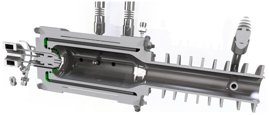
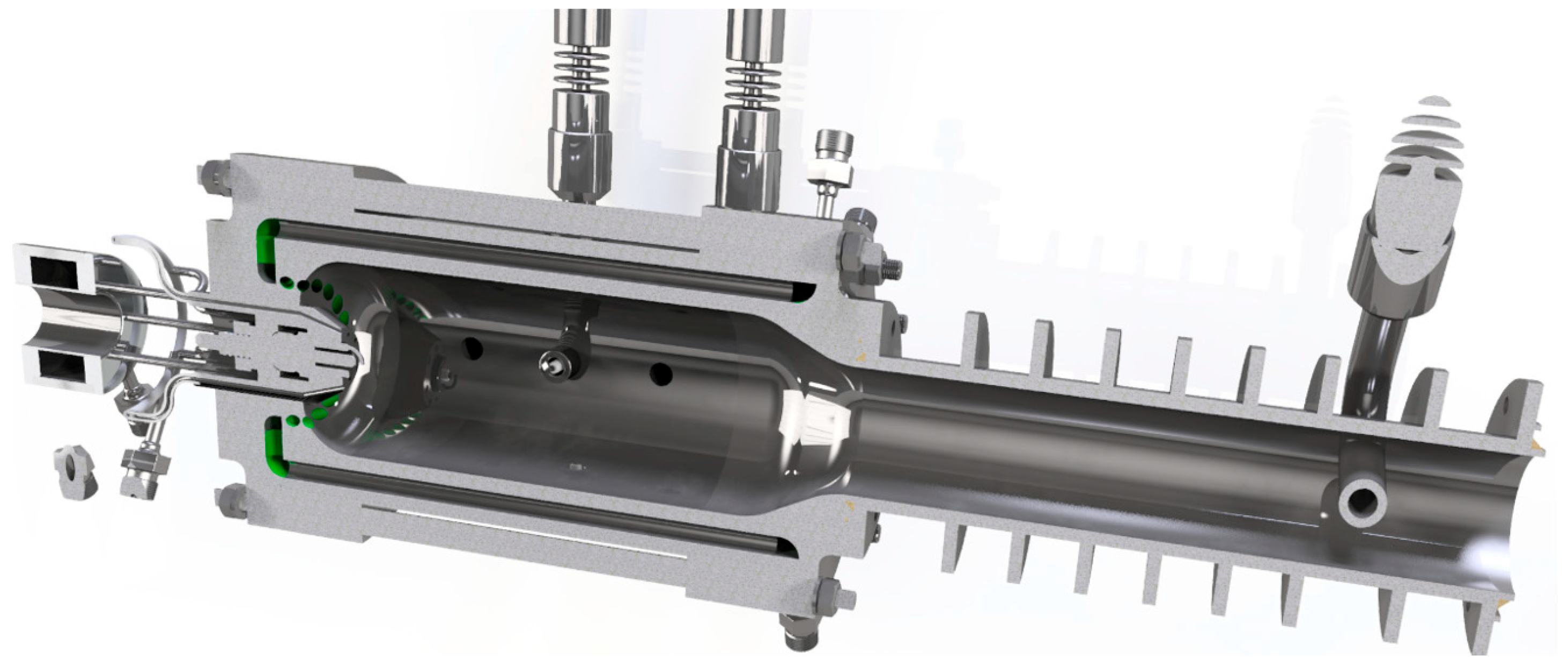
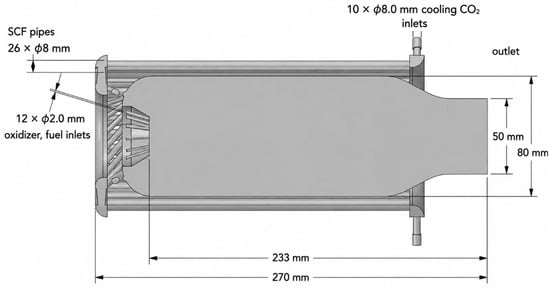
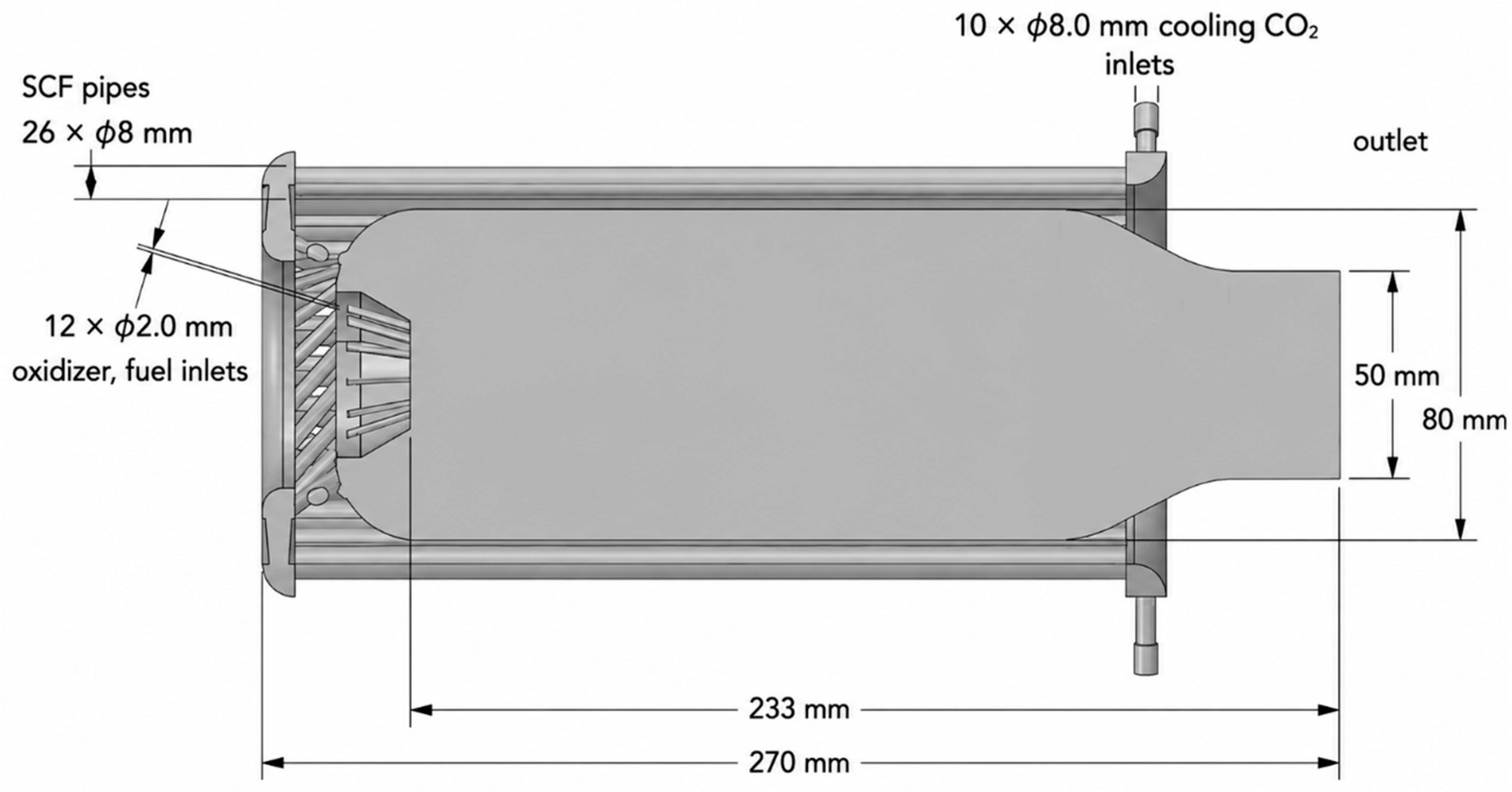
The combustion chamber (Figure 1) has a total internal volume of 1 L and operates at a constant pressure of 1 bar. The outer casing of the chamber incorporates integrated channels for carbon dioxide (CO2) circulation. The CO2 serves a dual purpose: (i) cooling the chamber walls and (ii) preheating the CO2 prior to its injection into the combustion zone. The preheated CO2 is introduced tangentially through multiple ports distributed along the inner wall, generating swirl and enhancing flame stability. Temperature measurements were carried out using two thermocouples installed along the combustor axis. Two CT300-1-B-N thermocouples equipped with NiCr–Ni measuring electrodes were installed along the combustor axis. One thermocouple was positioned closer to the combustor head, providing direct access to the chamber and enabling measurement of gas temperature in the near-injector region. The second thermocouple was located further downstream, allowing the assessment of temperature evolution along the chamber length. The distance between the burner outlet and the end of the combustion chamber was approximately 265 mm. The thermocouples were positioned approximately 53 mm and 133 mm downstream of the burner outlet, corresponding to about 20% and 50% of the chamber length, respectively.
Figure 1.
Combustor geometry.
A custom-built burner is mounted along the central axis of the chamber. The burner features twelve injection holes, each with a diameter of 2 mm, arranged in two concentric circles (six per ring) with a 2 mm radial offset. The configuration enables coaxial injection of hydrogen and oxidizer, with nozzle orientations designed to promote efficient mixing.
Hydrogen is supplied through the six inner injection holes (smaller diameter), with a mass flow rate ranging from 0.015 to 0.021 kg/min. The oxidizer mixture, consisting of oxygen and carbon dioxide, is introduced through the six outer injection holes at a volumetric ratio of 29% O2 to 71% CO2. In addition, cooling carbon dioxide is supplied at a mass flow rate of 1.7 kg/min.
Tests were conducted to evaluate the stability of combustion and to determine the minimum flammability limits for the designed burner and chamber. Another measured parameter was the temperature distribution inside the combustion chamber (denoted as temperature T2 in the graphs) and the exhaust gas temperature after the cooler (temperature T3 in the graphs). The external surface temperature of the combustion chamber shell and cooler was also measured.
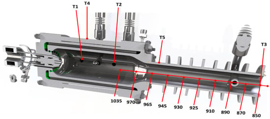
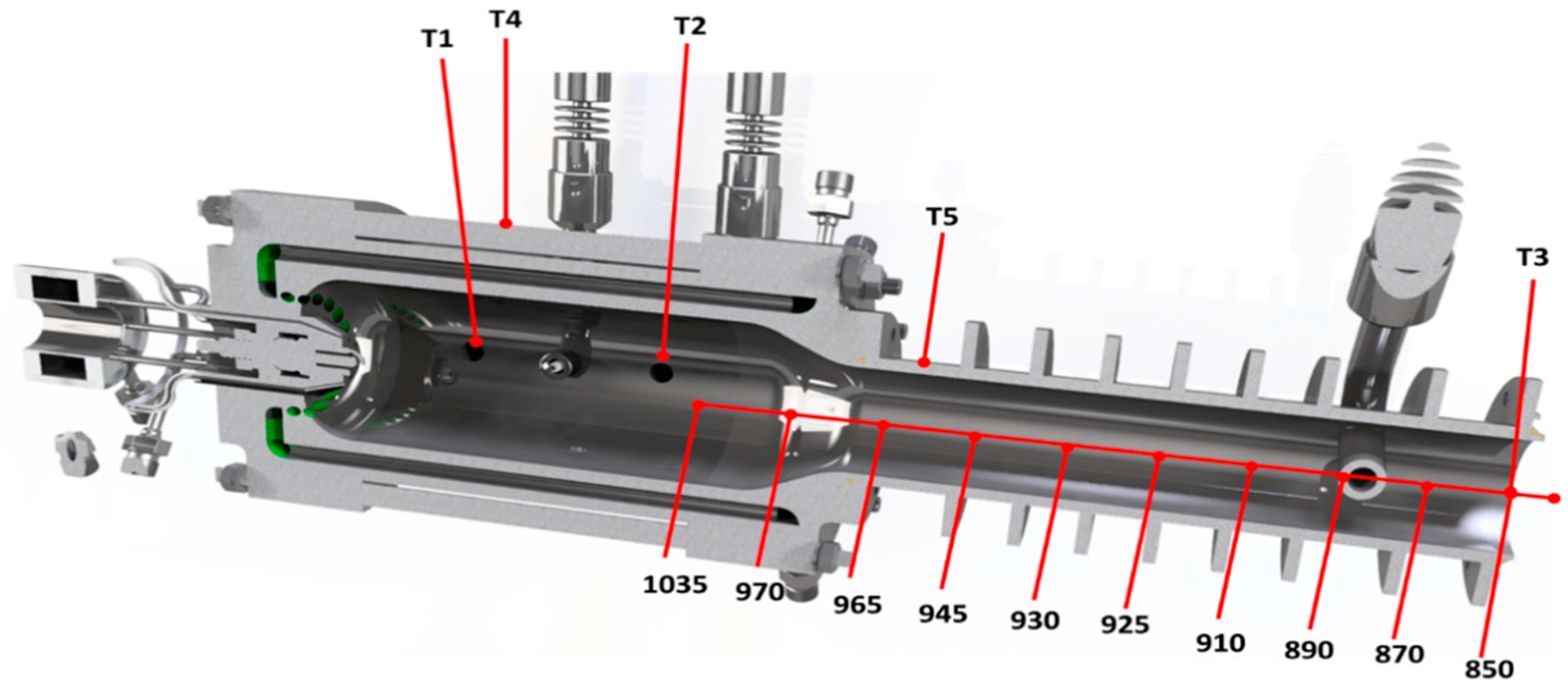
The arrangement of temperature measurement locations inside the combustor and cooling section is presented in Figure 2. Temperature measurements were performed at three characteristic locations along the combustor axis, denoted as T1, T2, and T3. The T1 location was positioned close to the injector region, while T2 was located inside the main combustion chamber. The T3 measurement point was situated downstream in the outlet cooling tube to evaluate the thermal evolution of flue gases during cooling.
Figure 2.
Scheme of a combustor with outlet tube (cooling-1).
The outlet section incorporates a cooling tube designed to reduce flue gas temperature before discharge. The temperatures presented in Figure 2 were obtained using an additional movable thermocouple inserted into the cooling tube. Measurements were performed at intervals of approximately 3 cm along the tube axis to determine the axial temperature distribution. These measurements were independent of the permanently installed thermocouples T1 and T2. The temperature decrease along the cooling section enabled the evaluation of the effectiveness of CO2-based thermal management within the system.
Experimental tests were carried out at inlet gas pressures of 10, 20, 30, 40, and 50 bar. For each test series at a given pressure, the initial test parameters were set for the nominally calculated combustion power of 42 kW. The flow rates of gases supplied to the chamber were as follows:
- H2—0.021 kg/min
- O2—0.21 kg/min
- CO2 (burner)—0.7 kg/min
- CO2 (cooling)—1.7 kg/min
The hydrogen flow rate to the burner was then gradually reduced to 0.013 kg/min. This resulted in test points corresponding to an excess oxidizer ratio ranging from 1.26 to 2.21 and a burner power range from 42 to 26 kW. Flame blowout occurred below a hydrogen flow rate of 0.015 kg/min.
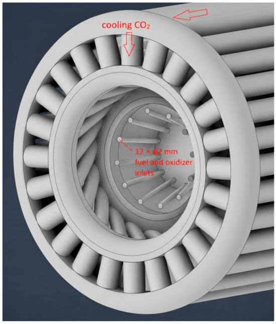
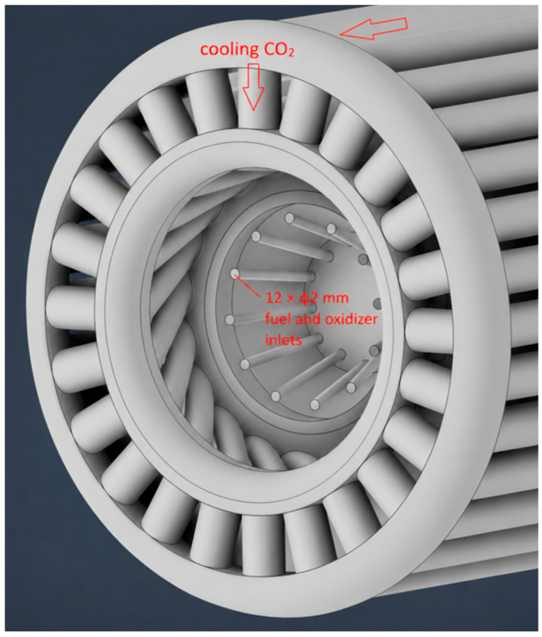
Figure 3 presents the fluid-domain representation of the combustor head used in the numerical simulations. The geometry shown corresponds to the fluid volume. The central region contains twelve injection channels with a diameter of 2 mm, arranged in two concentric rings and used for alternating fuel and oxidizer injection. Surrounding the burner head, a series of tangential cooling channels forms the flow path for the cooling CO2 stream. The cooling CO2 flows around the combustion chamber, providing thermal protection of the chamber walls and promoting swirl generation in the vicinity of the burner. The presented geometry was used to define the computational domain and boundary conditions for the CFD simulations.
Figure 3.
Combustor head geometry.
2.2. Numerical Setup
Figure 4 depicts the numerical geometry.
Figure 4.
Numerical domain of H2 combustor.
Numerical simulations were conducted using ANSYS Fluent 2024 R2 to replicate the experimental configuration. The computational domain reproduced the exact geometry of the burner and combustion chamber, including swirl-inducing tangential inlets.
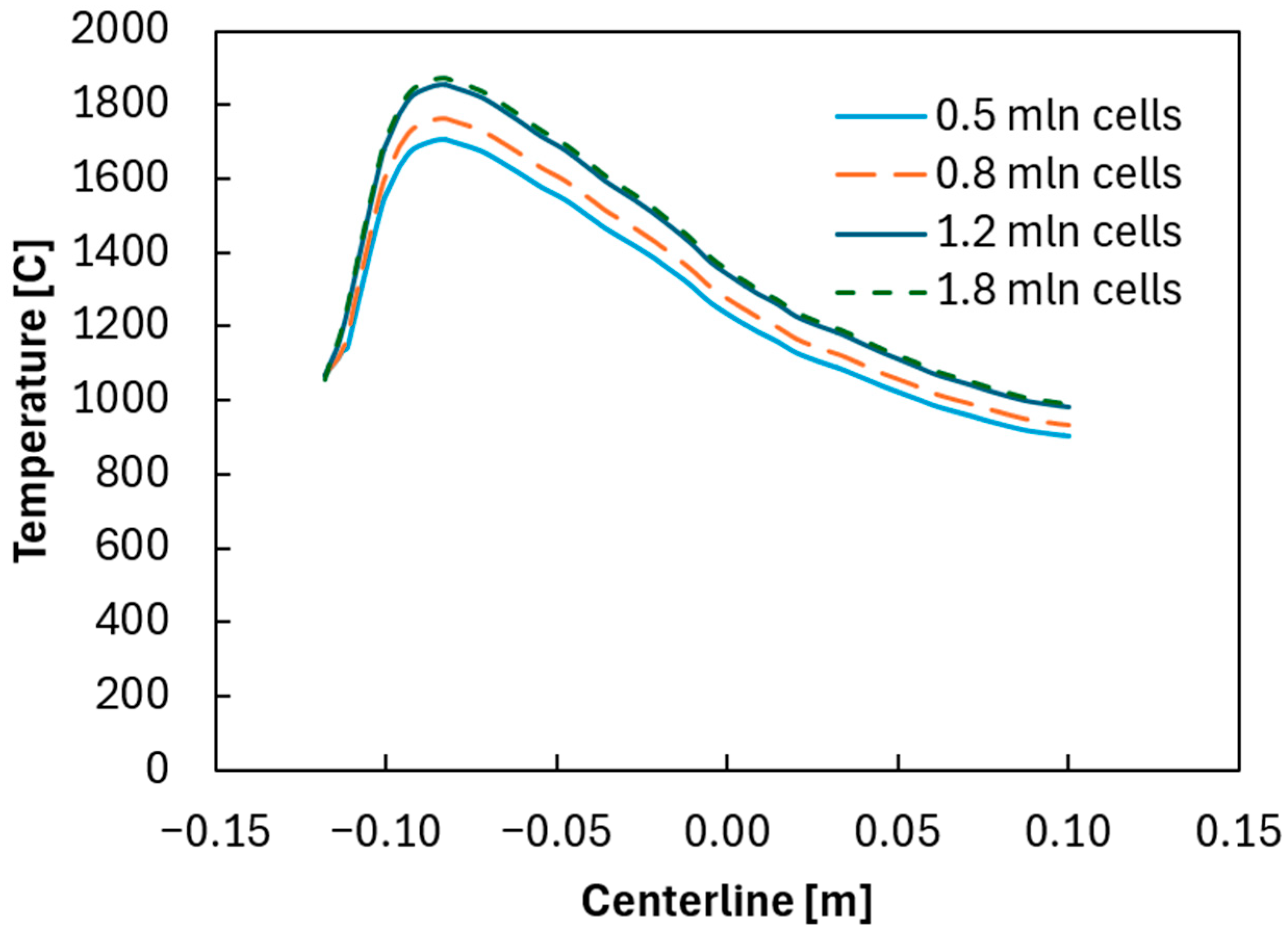
A mesh independence study was performed using four computational meshes containing approximately 0.5, 0.8, 1.2, and 1.8 million cells. Figure 5 compares the temperature distributions along the combustor centerline obtained for each mesh. The results indicate a noticeable dependence of the solution on mesh resolution for the coarse and medium meshes (0.5 and 0.8 million cells), particularly in the region of maximum temperature. Increasing the mesh density from 0.5 to 1.2 million cells resulted in a significant change in the predicted temperature field and peak temperature values.
Figure 5.
Mesh independence study—temperature distribution along the centerline.
In contrast, the temperature profiles obtained with the 1.2 and 1.8 million cell meshes are nearly identical over the entire investigated domain. The difference in the predicted peak temperature between these two meshes was below 2%, indicating that further mesh refinement has only a minor influence on the numerical results. Therefore, the mesh containing approximately 1.2 million cells was selected for all subsequent simulations as a compromise between computational cost and solution accuracy. The mesh quality was assessed using orthogonal quality and skewness metrics. The average and minimum orthogonal quality values were 0.78 and 0.21, respectively, while the average and maximum skewness values were 0.23 and 0.72. These values indicate good mesh quality and confirm the suitability of the computational grid for the performed simulations.
A pressure-based solver operating under steady-state assumptions was used throughout. The realizable k-ε approach was used in the current simulations. Radiative heat transfer was modeled using the Discrete Ordinates (DO) approach, while the absorption coefficient was determined via the Weighted Sum of Gray Gases Model (WSGGM). These established models are commonly employed in combustion analyses. The underlying equations and theoretical formulations are thoroughly detailed in the ANSYS Fluent Theory Guide. The interaction between combustion and chemistry was captured using the Eddy Dissipation Model (EDM). The global mechanism with four governing reactions was applied. Both approaches showed good agreement with experimental results, with EDM demonstrating improved numerical stability and convergence in more simplified cases.
A four-step global mechanism is used (Table 1).
Table 1.
Global reaction mechanism applied.
Application of the global mechanism is justified by [24]. The results reported in [24] showed that the Eddy Dissipation Model (EDM) combined with a global four-step mechanism produced results in close agreement with those obtained using the Eddy Dissipation Concept (EDC) and the detailed FFCM-1 mechanism consisting of 38 species and 291 reactions. Therefore, to reduce computational cost, the former approach was adopted in the present study. Refs. [23,24] are in fact directly related publications and are strictly related to hydrogen combustion in high CO2-environment conditions.
The swirling flow pattern generated by the burner plays a critical role in flame stabilization. The simulation accounted for this using momentum source terms aligned with the tangential injection scheme. Grid independence was verified, and convergence was ensured through residual monitoring and comparison against experimental temperature profiles.
2.3. Measurement Uncertainty
The uncertainty of the experimental measurements was estimated based on instrument specifications, repeatability of the experiments, and signal fluctuations observed during operation. Temperature measurements performed using thermocouples were associated with an estimated uncertainty of approximately ±5 °C. Pressure measurements were characterized by an uncertainty of ±1 bar, while the uncertainty of gas mass flow rates was estimated to remain below ±3% of the measured value.
The visible flame length determined from optical observations was associated with an uncertainty of approximately ±1 cm due to flame luminosity fluctuations and difficulties in defining the exact boundary of the visible reaction zone during transient operation.
Numerical uncertainty was minimized through mesh independence verification and convergence monitoring of residuals and characteristic temperature values.
3. Results and Discussion
3.1. Experimental Results
The key part of the experimental investigation consisted of a temperature distribution analysis inside the combustor for different oxygen excess ratios, pressures, and outlet gas compositions.
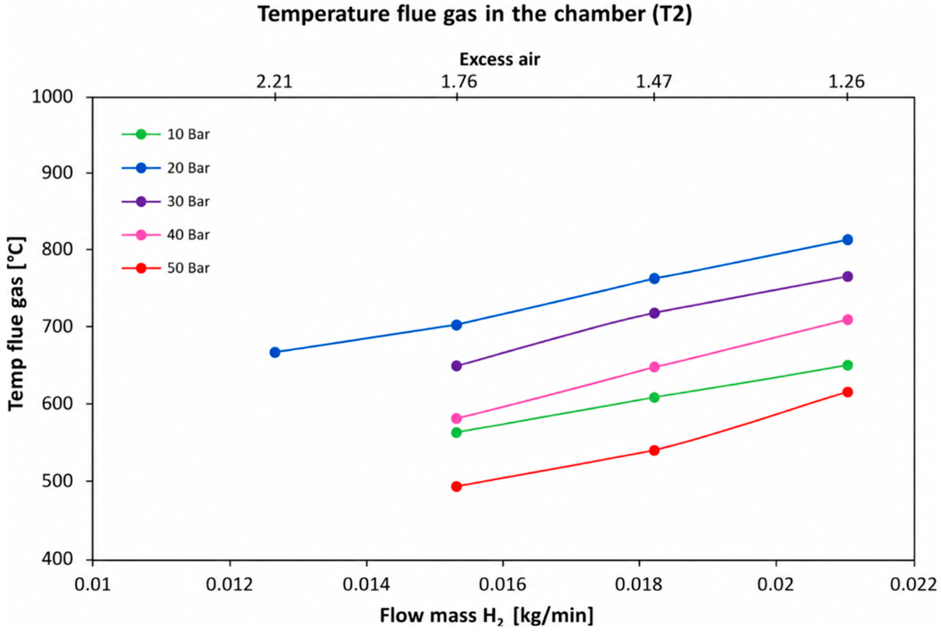
Figure 6 displays the flue gas temperature in the combustion chamber as a function of hydrogen mass flow rate under different pressures. In all cases, increasing the hydrogen flow rate leads to a rise in flue gas temperature, reflecting increased energy input. At a given flow rate, pressure significantly affects temperature: 20 bar consistently yields the highest flue gas temperatures, followed by 30 bar, 40 bar, 10 bar, and the lowest values at 50 bar. This suggests that moderate reactant inlet pressures result in the highest measured flue gas temperatures, whereas a further increase to 50 bar leads to a temperature decrease. The observed behavior indicates that the relationship between reactant inlet pressure and measured flue gas temperature is non-linear and is influenced by changes in flame structure and heat release distribution within the combustor.
Figure 6.
Flue gas temperature in the combustion chamber (T2 in Figure 2).
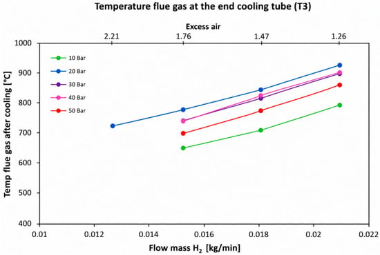
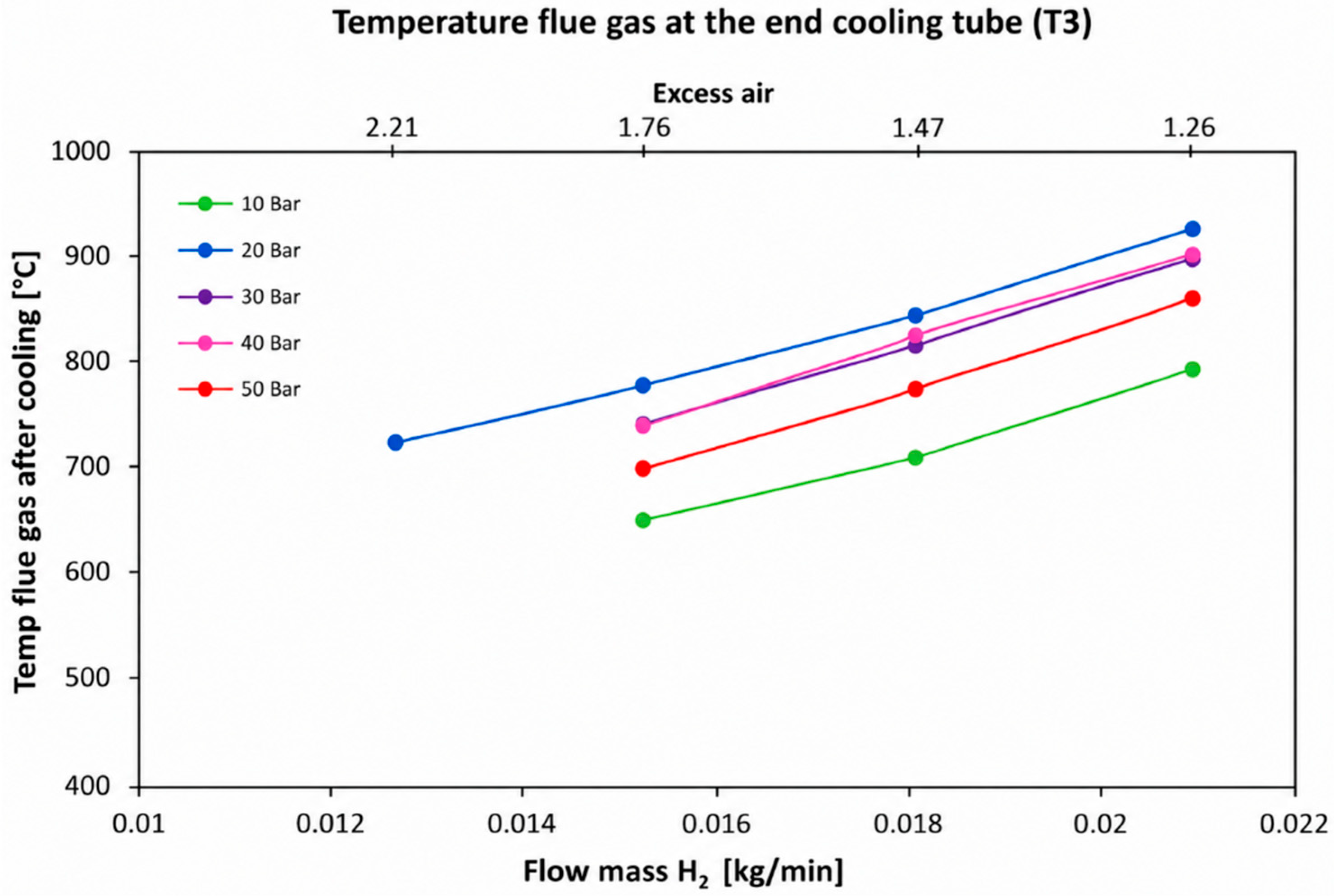
Figure 7 illustrates the flue gas temperature at the end of the cooling tube as a function of hydrogen mass flow rate under different combustor pressures. Across all pressures, the flue gas temperature increases with rising hydrogen flow rate, indicating a correlation with higher heat release. At a constant flow rate, pressure also influences the temperature: the highest temperatures are observed at 20 and 30 bar, while 10 bar and 50 bar yield lower temperatures. The lowest temperatures occur at 10 bar, and temperatures tend to decrease again at 50 bar, suggesting an optimal pressure range for maximum flue gas temperature. Excess air decreases as hydrogen flow increases, reinforcing the role of air-fuel ratio in temperature regulation.
Figure 7.
Flue gas temperature at the end of the cooling tube (T3 in Figure 2).
3.2. Numerical Results
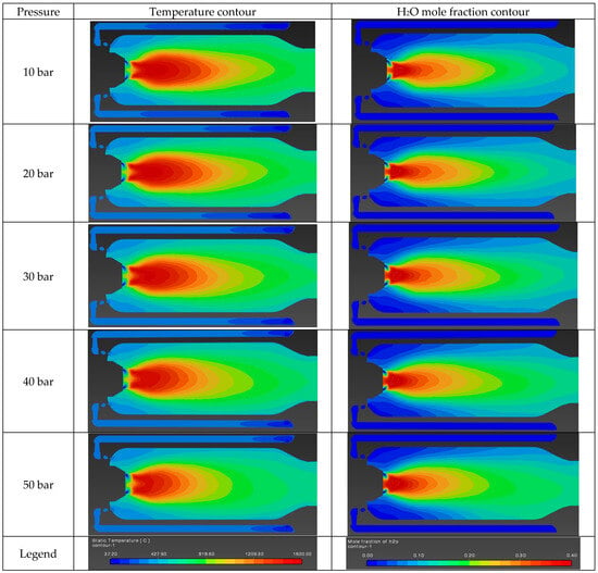
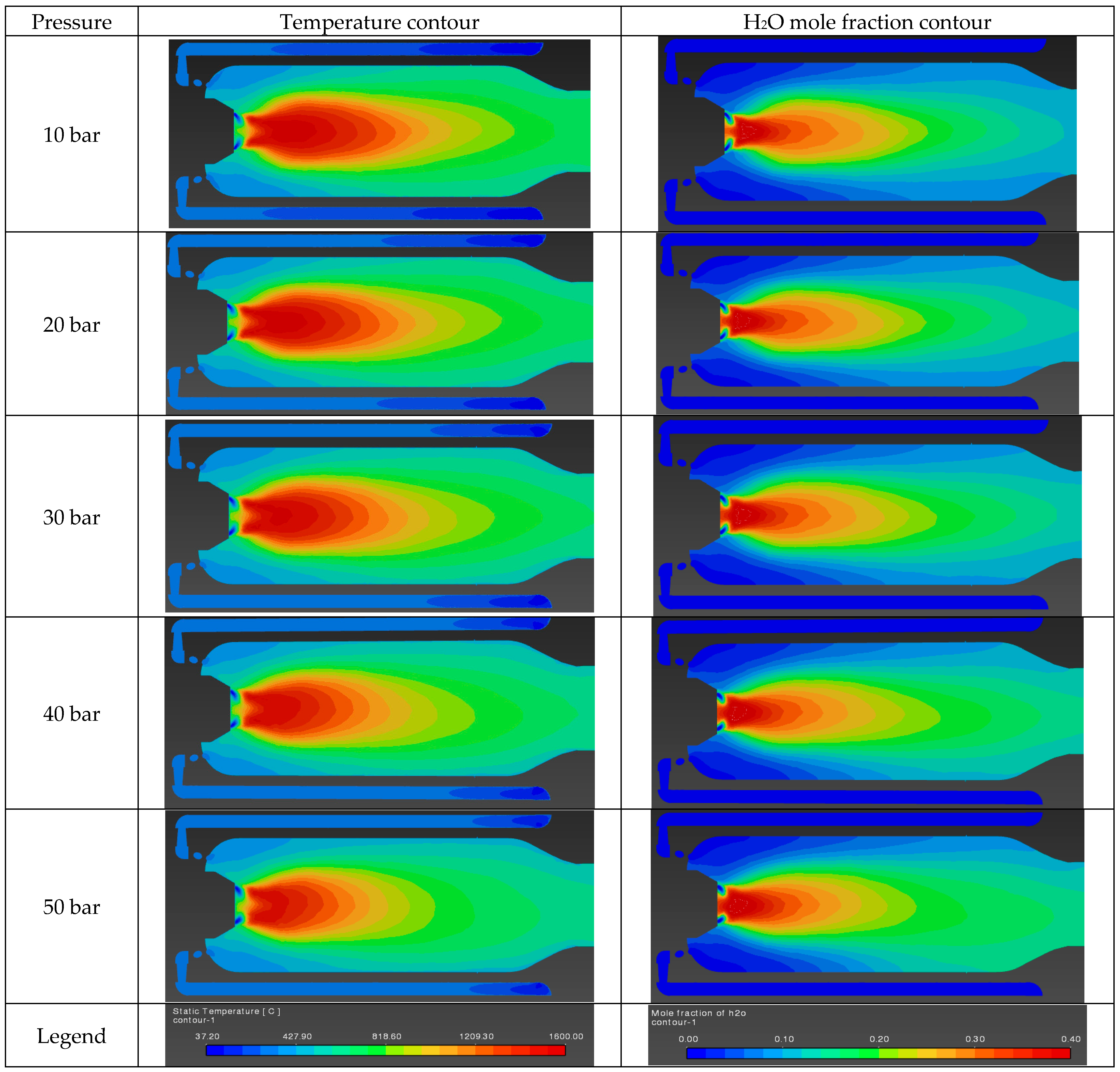
Figure 8 presents temperature (left column) and H2O mole fraction (right column) contours inside the combustor for increasing inlet pressures (10–50 bar), with the chamber pressure fixed at 1 bar. In all cases, a jet-driven flame forms downstream of the injector, characterized by a high-temperature and high-product core aligned with the flow direction.
Figure 8.
Temperature and H2O mole fraction contours of investigated cases (10–50 bar).
At 10 bar, the flame is long and relatively diffuse. The high-temperature region extends far downstream, and both temperature and H2O fields show significant radial spreading. This indicates that mixing occurs over a larger volume, leading to a more distributed reaction zone and gradual heat release. As the inlet pressure increases to 20 and 30 bar, the flame becomes progressively shorter and more concentrated. The peak temperature region shifts closer to the injector, and the axial extent of both the temperature and H2O fields decreases. Radial gradients become steeper, indicating a more confined reaction zone.
At 40–50 bar, the flame is clearly compact and highly localized near the injector. Similar modifications of flame structure and combustion behavior under increased reactant density and CO2 dilution were previously reported in studies of hydrogen oxy-combustion systems [19,26,27]. The high-temperature core is shorter, with a rapid decay in temperature downstream. Similarly, the region of high H2O mole fraction is a bit more confined to a smaller axial distance, confirming that combustion is completed earlier. The surrounding regions remain relatively cold and lean in products, indicating limited large-scale mixing. The H2O mole fraction contours closely follow the temperature field, as expected for hydrogen combustion. The coincidence of peak temperature and peak H2O regions confirms that the main reaction zone becomes more compact and shifts toward the injector with increasing inlet pressure.
Overall, increasing inlet pressure at constant chamber pressure leads to a transition from a long, distributed flame to a short, intense, and localized reaction zone, governed by the interplay between reduced large-scale mixing and enhanced reaction rates.
Table 2 presents the mean and maximum combustor temperatures for inlet pressures ranging from 10 to 50 bar. As the inlet pressure increases, the maximum temperature rises steadily from 1530 °C at 10 bar to 1619 °C at 50 bar, while the mean combustor temperature decreases from 693 °C to 612 °C.
Table 2.
Mean and maximum combustor temperatures for given conditions.
These trends are consistent with the previously observed flame structure. The increase in maximum temperature reflects the formation of a more intense and localized reaction zone near the injector at higher inlet pressures. At the same time, the decrease in mean temperature indicates that a larger portion of the combustor volume remains at lower temperatures.
This behavior confirms that, with increasing inlet pressure, combustion becomes more concentrated and occurs over a shorter axial distance, leading to a compact flame with higher peak temperatures but reduced overall thermal uniformity within the chamber.
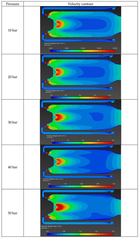
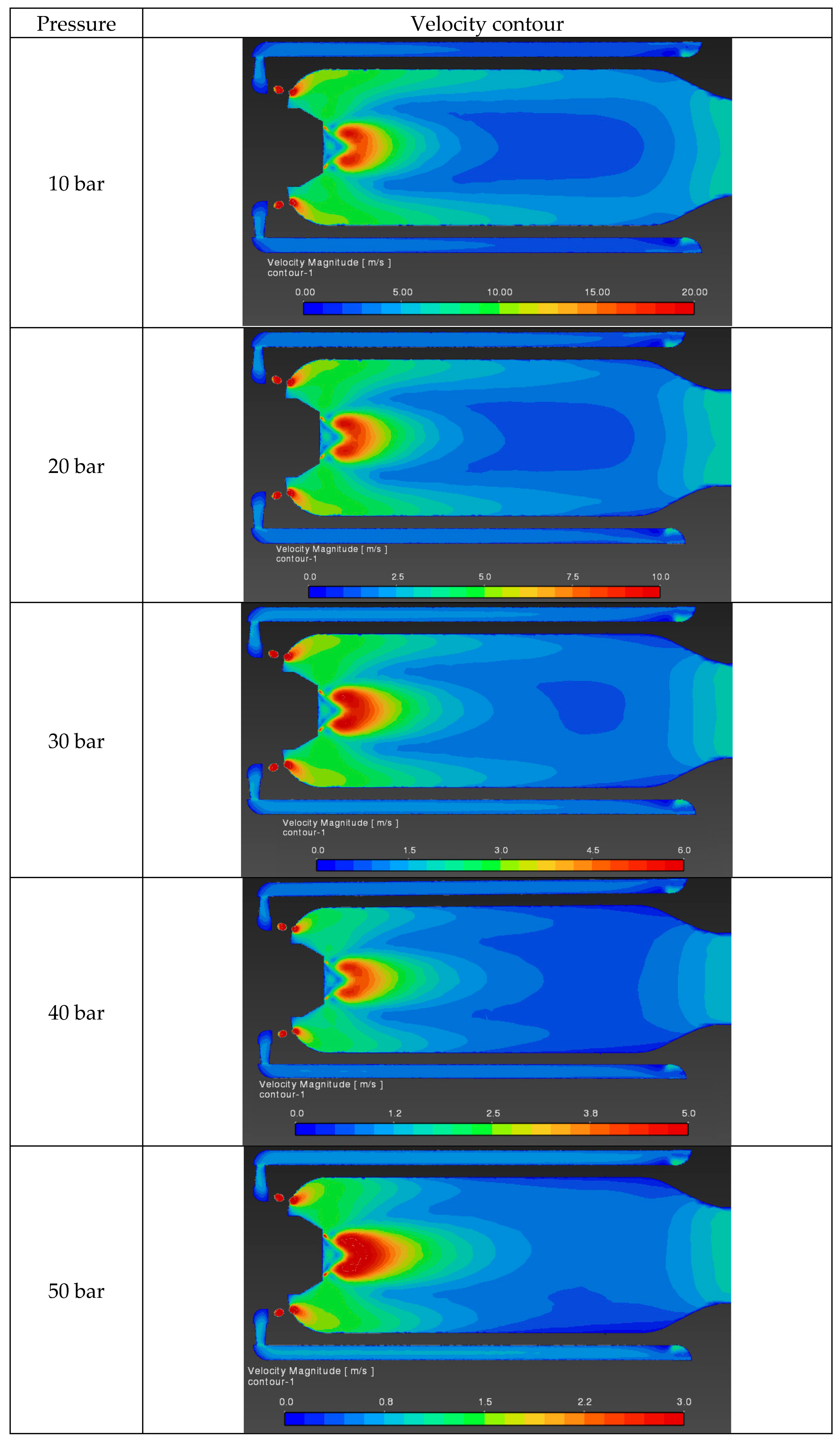
The velocity contours (Figure 9) for different inlet pressures exhibit a very similar spatial distribution, indicating that the overall flow structure inside the combustor does not change significantly with increasing inlet pressure. In all cases, a jet-like flow is observed, with the highest velocities located near the injector and a gradual decay downstream. However, the velocity magnitude decreases with increasing inlet pressure, as indicated by the different contour scales. A similar reduction in jet velocity for constant mass flow conditions at elevated reactant density was previously reported in studies of hydrogen combustion systems operating under pressurized conditions [15]. This behavior is associated with the increase in reactant density at higher inlet pressures. For a given mass flow rate, higher density results in lower flow velocities, consistent with the continuity relation. As a result, although the flow topology remains largely unchanged, the absolute velocity levels are reduced at higher inlet pressures. This implies longer residence times and contributes to the observed shortening of the flame and earlier completion of combustion.
Figure 9.
Velocity contours of investigated cases (10–50 bar).
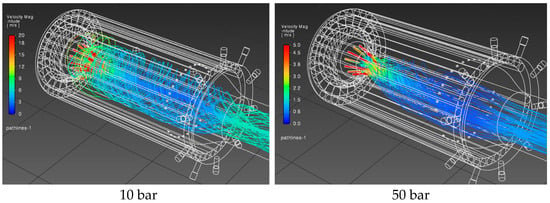
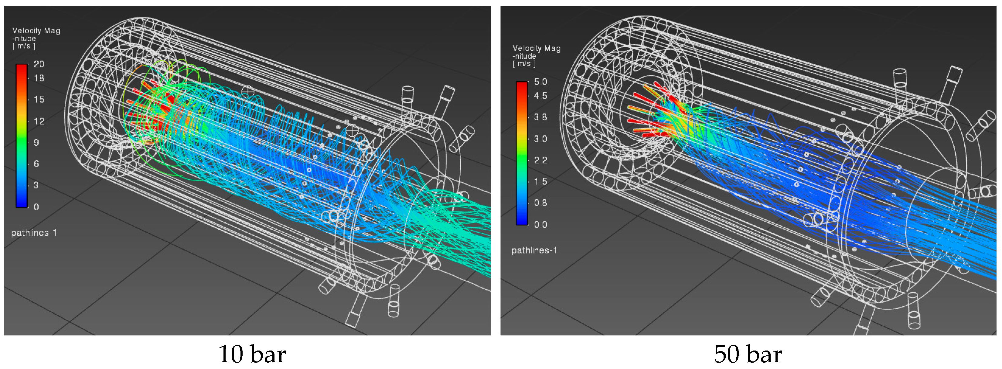
Figure 10 presents velocity pathlines colored by velocity magnitude for two cases: 10 bar and 50 bar inlet pressure, with the chamber pressure maintained at 1 bar. The pathlines illustrate the trajectories of fluid particles and provide insight into the flow structure and mixing behavior inside the combustor. At 10 bar, the pathlines exhibit noticeable radial dispersion shortly after injection. The flow spreads outward from the injector, and the trajectories show stronger deviation from the axial direction. This indicates more effective large-scale mixing and entrainment of the surrounding fluid. The velocity magnitude decreases gradually along with the flow direction, consistent with the broader and more diffused jet observed in the contour plots.
Figure 10.
Velocity pathlines for 10 and 50 bar.
At 50 bar, the pathlines are significantly more aligned with the axial direction, forming a more coherent and focused jet. The trajectories show reduced radial spreading, and the flow remains confined to a narrower region along the combustor axis. This indicates weaker large-scale mixing and a more organized, jet-like flow structure. Additionally, the overall velocity magnitude is lower compared to the 10-bar case, as reflected by the color scale. The comparison confirms that increasing inlet pressure leads to a more collimated and less dispersive flow, despite the reduction in absolute velocity magnitude. This results in reduced global mixing but increased residence time, which supports the earlier observation of a shorter and more localized flame at higher inlet pressures.
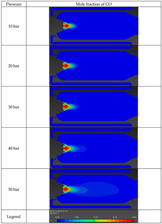
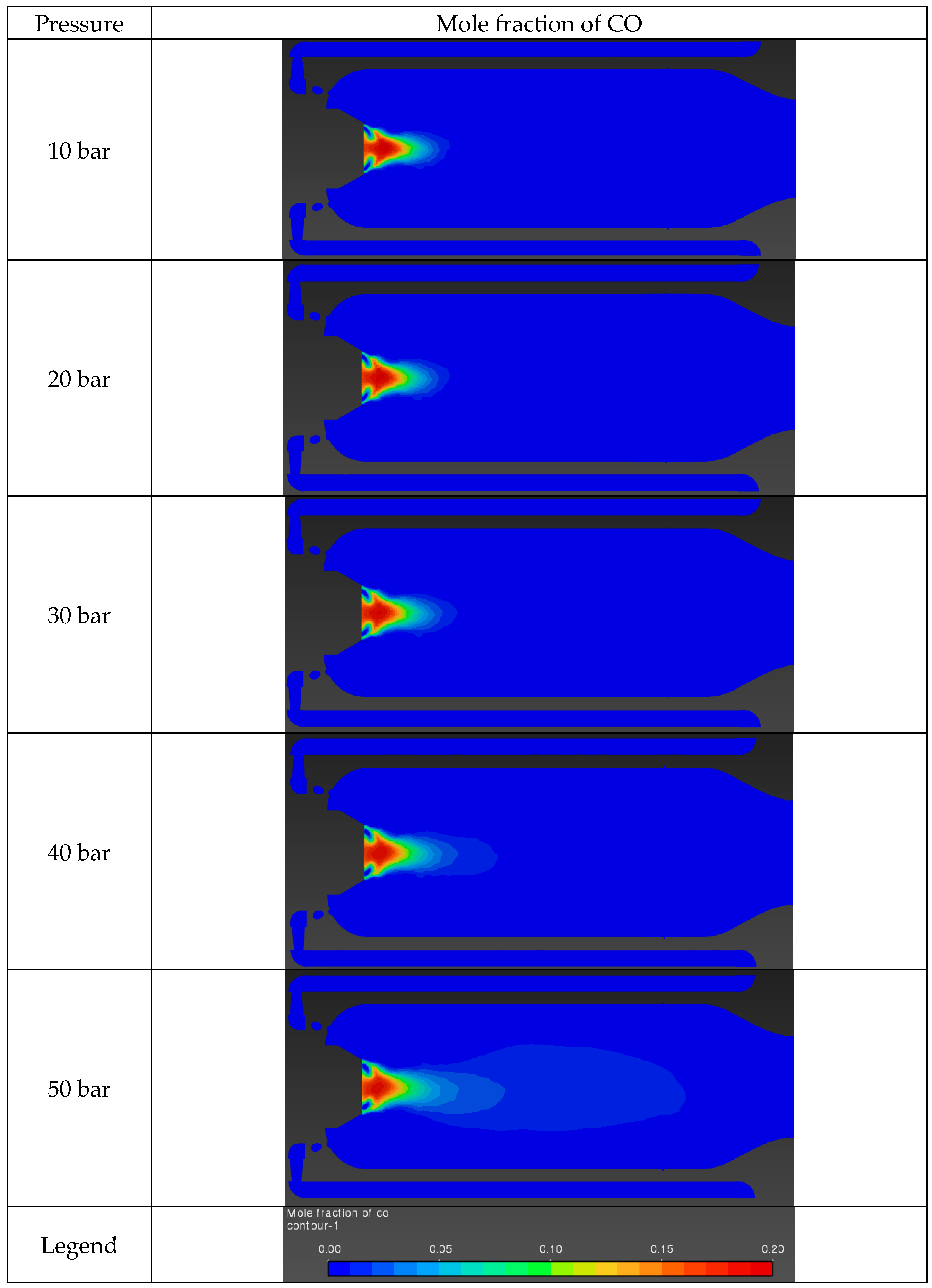
Figure 11 presents the mole fraction of CO inside the combustor for inlet pressures ranging from 10 to 50 bar, with the chamber operating at 1 bar. In all cases, CO is formed primarily in the high-temperature region near the injector, where thermal decomposition of CO2 occurs: . At 10 bar, the CO is confined to a relatively small region close to the reaction zone, with a sharp decay downstream. This indicates that CO is produced locally at high temperatures and rapidly diminishes as the gases cool and recombine. As the inlet pressure increases to 20 and 30 bar, the region of elevated CO mole fraction becomes slightly more extended downstream, while remaining concentrated along the burner axis. The peak values remain localized near the injector, consistent with the location of maximum temperature. At 40 and 50 bar, the CO distribution becomes noticeably more elongated, with a low but non-negligible CO presence extending further into the combustor. This corresponds to the formation of a broader region of intermediate CO levels downstream of the primary reaction zone. The CO observed in these simulations is not a product of incomplete combustion in the classical sense but a result of high-temperature equilibrium effects.
Figure 11.
Mole fraction of CO for different inlet pressures (10–50 bar).
3.3. Comparison of Experimental and Numerical Results
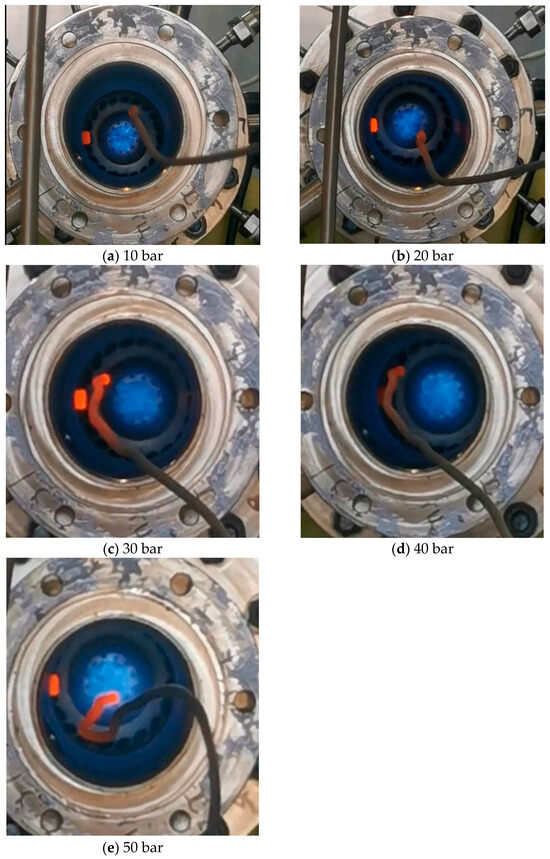
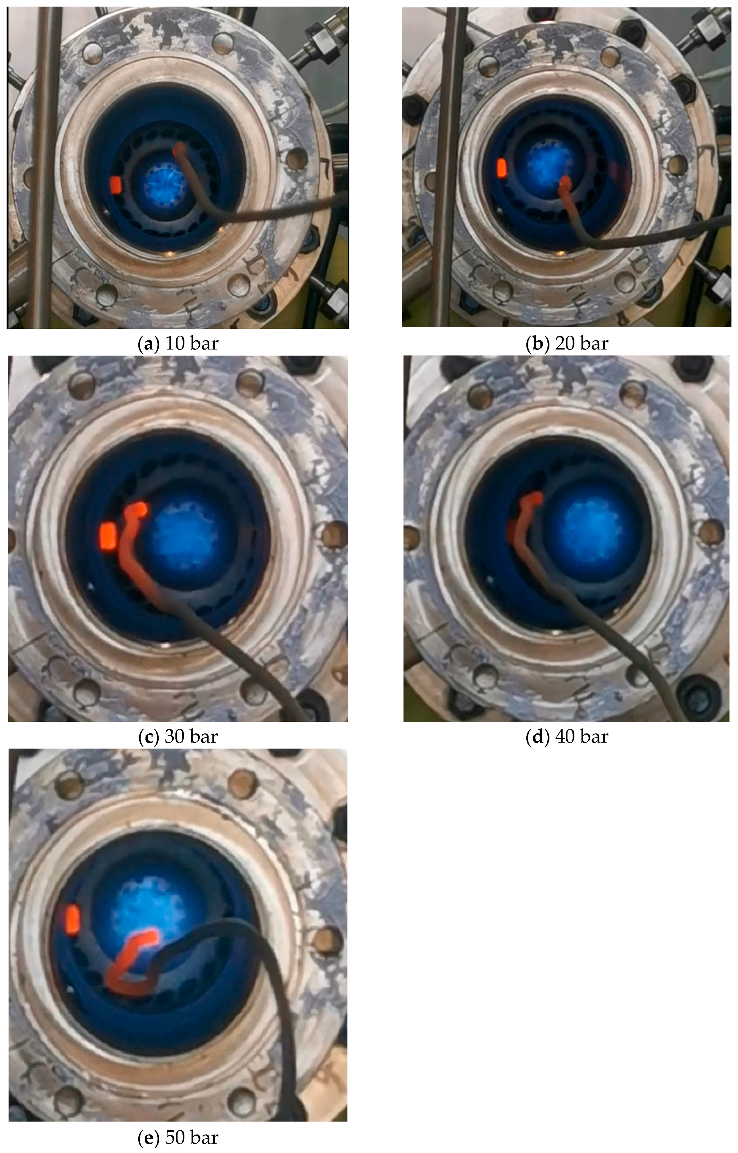
Figure 12 presents the visual appearance of the hydrogen flame inside the combustor for different inlet pressures of the reactants (10–50 bar), while the chamber itself operates at atmospheric pressure (1 bar). The images show a front view of the flame through the optical access of the combustor. As the inlet pressure increases, the flame becomes visibly more compact and confined, with a reduction in its apparent spatial extent. At 10 bar (a), the flame appears relatively diffuse and less intense, with a broader luminous region and lower optical density. As the inlet pressure increases to 20 and 30 bar (b–c), the flame gradually becomes more concentrated near the burner axis, and its structure becomes more clearly defined.
Figure 12.
Front view of the (a) 10-bar, (b) 20-bar, (c) 30-bar, (d) 40-bar, and (e) 50-bar hydrogen flame inside the combustor.
At higher inlet pressures (40–50 bar, d–e), the flame is distinctly compact, stable, and well-confined, with a reduced visible volume. This observation is consistent with the numerical results, which indicate a shorter reaction zone and more localized heat release at higher inlet pressures.
The flame exhibits a characteristic blue coloration, typical of hydrogen combustion, indicating a clean process with negligible soot formation. The visible emission is dominated by excited radicals (e.g., OH*), while the absence of yellow luminosity confirms minimal particulate radiation. The brighter regions observed near the injector and along certain structural elements correspond to metal surfaces heated by radiative heat transfer from the flame, rather than to combustion zones.
Between the lowest and highest inlet pressures, the flame appears optically brighter and more intense, particularly in case (e). This effect is associated with increased gas density, which enhances radiative emission and light scattering, leading to a denser visual appearance of the flame. Importantly, this optical intensification does not indicate a longer flame but rather a more concentrated and energetic reaction zone.
The flame remains stable and approximately axisymmetric across all cases, indicating effective interaction between the fuel, oxidizer, and the tangentially injected CO2. No signs of flame blow-off or significant asymmetry are observed, suggesting that the burner design ensures robust operation over the investigated range of inlet pressures.
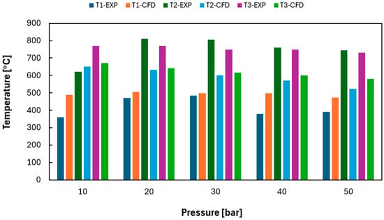
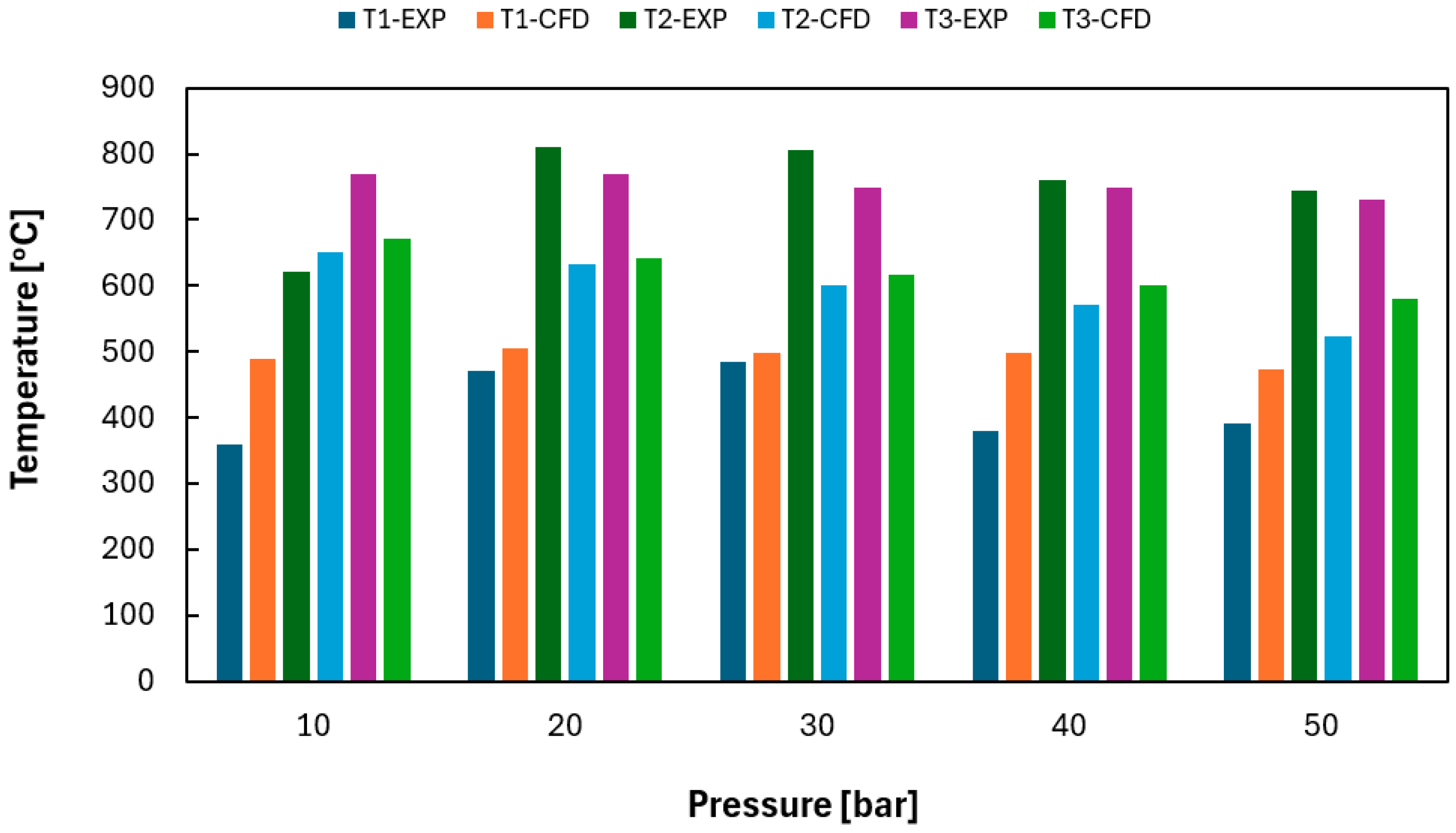
Figure 13 compares experimental (EXP) and numerical (CFD) temperatures at three axial locations inside the combustor: T1 (near the inlet), T2 (mid-chamber), and T3 (outlet), for inlet pressures ranging from 10 to 50 bar—T1, T2, and T3 are depicted in Figure 3. In both experimental and numerical results, a clear increase in temperature along the chamber axis is observed. This reflects the progressive heat release and downstream transport of thermal energy within the combustor. At T1, the CFD results consistently overpredict the experimentally measured temperatures. This indicates that the numerical model predicts a more intense heat release close to the injector region than observed experimentally during the initial stage of operation. In contrast, at T2, the CFD simulations underpredict the measured temperatures, suggesting that the numerical model may underestimate downstream heat transfer and turbulent mixing development inside the combustor. Table 3 presents a quantitative error analysis between the experimentally measured temperatures and the CFD predictions at the three measurement locations (T1, T2, and T3) for all investigated inlet pressures. The relative error was calculated based on the difference between numerical and experimental values.
Figure 13.
Temperatures obtained from experiments and CFD. Those temperatures correspond to temperatures (T1, T2, T3) shown in Figure 3.
Table 3.
Error analysis.
The results indicate that the CFD model reproduces the overall temperature trends observed in the experiments; however, noticeable quantitative discrepancies remain. The smallest deviations were observed at selected operating conditions for T1, where the error was below 10%, while the largest deviations occurred at T2 and T3, reaching approximately 30% for some cases. On average, the relative errors were approximately 19.5%, 21.1%, and 17.1% for T1, T2, and T3, respectively.
The observed discrepancies are associated with several factors. First, the experimental measurements were performed during the startup and transient operation of the combustor, whereas the CFD simulations represent fully developed steady-state conditions. Consequently, temporal fluctuations and thermal stabilization effects present in the experiments cannot be fully captured by the numerical model.
Second, the combustion process was modeled using the Eddy Dissipation Model (EDM) combined with a global four-step reaction mechanism. Although this approach provides satisfactory computational efficiency and reproduces the overall combustion behavior, it may not accurately predict local reaction rates and heat release distribution under highly CO2-diluted conditions. Additional discrepancies may arise from the simplified turbulence-chemistry interaction treatment.
Furthermore, uncertainties associated with thermocouple measurements, wall heat losses, and radiative heat transfer modeling may also contribute to the observed temperature differences. In particular, radiation modeling in hydrogen oxy-combustion systems containing significant amounts of CO2 remains challenging due to the strong radiative properties of combustion products and participating gases.
Despite these quantitative differences, both experimental observations and CFD simulations consistently indicate the same qualitative combustion trends, including flame stabilization under highly CO2-diluted conditions and progressive localization of the reaction zone with increasing inlet pressure.
Table 4 presents the mean visible flame length obtained from experiments (EXP) and CFD simulations for inlet pressures ranging from 10 to 50 bar, while the combustion chamber operates at atmospheric pressure (1 bar). The length was estimated from video recordings obtained during the experiments. A graduated scale placed along the combustion chamber was used as a reference for length measurements. Due to the dynamic nature of the flame, the reported values correspond to average visible flame lengths determined from the recorded videos.
Table 4.
Mean visible flame length for experiment and CFD.
The experimental results show that the visible flame length remains approximately constant, at about 13.0 ± 1.0 cm, across all investigated pressure conditions. This indicates that, within the uncertainty of the measurements, the inlet pressure does not significantly affect the visible flame length during the experimental observations.
In contrast, the CFD results predict a clear decrease in flame length with increasing inlet pressure, from 13.5 cm at 10 bar to 9.0 cm at 50 bar. This trend is consistent with the previously discussed numerical results, which showed a more compact and localized reaction zone at higher inlet pressures due to increased reactant density and faster chemical kinetics.
The discrepancy between experimental and numerical results can be explained by the different nature of the data. The experimental visible flame length corresponds to the visible luminous region, which is influenced by optical effects, transient operation, and measurement uncertainty. As observed in the flame images, the apparent size of the flame does not change significantly, even though its internal structure evolves.
On the other hand, the CFD-based flame length is derived from temperature or reaction rate fields, which provide a more direct representation of the actual reaction zone. These results indicate that the physical flame becomes shorter with increasing inlet pressure, even if this effect is not clearly visible in the experimental images.
Additionally, it should be noted that the experiments were conducted during the initial transient phase, whereas the CFD simulations represent a steady-state solution. This difference further contributes to the observed discrepancy.
Overall, the CFD results suggest a pressure-dependent reduction in flame length, consistent with the trends observed in temperature and species fields, while the experimental measurements indicate that the visible flame length remains approximately constant within the measurement uncertainty.
3.4. Practical Implications for Supercritical CO2 Combustion
The obtained results have important implications for the development of future direct-fired combustors dedicated to supercritical CO2 power cycles. The numerical and experimental investigations demonstrated that increasing reactant inlet pressure promotes the formation of a more compact and localized flame while maintaining stable combustion under highly CO2-diluted conditions. Such behavior is particularly desirable in practical sCO2 systems, where combustor size should be minimized to reduce investment costs and facilitate integration with high-pressure turbomachinery.
The observed shortening of the reaction zone suggests that efficient combustion can be achieved within a smaller combustion volume, potentially enabling more compact combustor designs. Furthermore, stable flame operation over the investigated pressure range indicates that the proposed burner configuration may provide reliable combustion under conditions characterized by high reactant densities and significant CO2 recirculation, which are typical for Allam-cycle-based systems.
The results also indicate that elevated reactant pressures lead to higher local peak temperatures while preserving overall flame stability. This phenomenon may improve combustion intensity and facilitate the achievement of turbine inlet temperatures required for high cycle efficiencies. Consequently, the presented findings provide useful guidelines for the design of hydrogen-fueled combustors intended for future low-emission power generation systems based on supercritical CO2 technology.
4. Conclusions
Numerical modeling helped evaluate the mixing and combustion characteristics under high CO2 dilution conditions, while experimental studies analyzed the effect of varying CO2 concentrations, including an additional cooling CO2 stream. The following conclusions can be drawn from the research:
- The study demonstrates stable hydrogen flame propagation in an environment with over 70% CO2 dilution and gas inlet pressures up to 50 bar.
- Flame length decreases with pressure. The H2O distribution confirms what the temperature plots already showed: higher pressure produces a more compact, quenched flame.
- Maximum H2O concentration (~0.4) is roughly constant across all conditions, so the total combustion chemistry is not suppressed—only the flame shape changes.
- The temperature along the cooling tube decreases steadily with distance from the burner, confirming the effectiveness of CO2 cooling.
- The numerical results showed that increasing the reactant inlet pressure from 10 to 50 bar led to a progressive localization of the combustion zone. The maximum combustor temperature increased from 1530 °C to 1619 °C, corresponding to an increase of approximately 5.8%, while the average combustor temperature decreased from 693 °C to 612 °C, representing a reduction of approximately 11.7%. These results indicate that elevated reactant pressures promote the formation of a more compact and intense reaction zone while maintaining stable combustion under highly CO2-diluted conditions.
- The numerical simulations successfully reproduced the main combustion characteristics observed experimentally, including flame stabilization, temperature distribution trends, and reaction zone localization. Although quantitative discrepancies between experimental and numerical temperatures were observed, the CFD model provided a useful tool for analyzing the influence of reactant inlet pressure on combustion behavior.
In most tested scenarios, stable flame propagation was successfully achieved, providing valuable insights into the feasibility of hydrogen oxy-combustion under high CO2 dilution conditions.
From the perspective of energy system development, the obtained results indicate that hydrogen oxy-combustion under high CO2 dilution may support the design of compact and thermally efficient combustors dedicated to direct-fired supercritical CO2 cycles. The observed stable flame operation over a broad range of injection conditions demonstrates the potential applicability of such combustion systems in future low-emission hydrogen-based power technologies.
Author Contributions
Conceptualization, J.M., M.C., P.B., M.K. and H.P.-K.; methodology, J.M., M.C., P.B., M.K., D.P. and H.P.-K.; software, J.M.; validation, M.C., P.B. and M.K.; formal analysis, J.M., M.C., P.B. and M.K.; investigation, J.M., M.C., P.B., M.K. and D.P.; data curation, J.M., M.C., P.B. and M.K.; writing—original draft preparation, J.M. and M.C.; writing—review and editing, T.H. and H.P.-K.; visualization, J.M., M.C., P.B. and M.K.; supervision, T.H. and H.P.-K.; funding acquisition, H.P.-K. All authors have read and agreed to the published version of the manuscript.
Funding
The research received no external funding.
Data Availability Statement
The data presented in this study are available on request from the corresponding author.
Acknowledgments
This research was carried out within the framework of the HERMES project under the European Union grant No. 101083748. It received no external funding.
Conflicts of Interest
The authors declare no conflicts of interest.
References
- The Glasgow Climate Pact—Key Outcomes from COP26. Available online: https://unfccc.int/process-and-meetings/the-paris-agreement/the-glasgow-climate-pact-key-outcomes-from-cop26 (accessed on 14 March 2026).
- Reale, F. The Allam Cycle: A Review of Numerical Modeling Approaches. Energies 2023, 16, 7678. [Google Scholar] [CrossRef] [Scilit]
- Chan, W.; Morosuk, T.; Li, X.; Li, H. Allam Cycle: Review of Research and Development. Energy Convers. Manag. 2023, 294, 117607. [Google Scholar] [CrossRef] [Scilit]
- Xie, M.; Chen, X.; Chen, L.; Zhou, M.; Liu, Y.; Zeng, L.; Shi, H.; Zhang, F.; Xie, S.; Zhao, Y. Evaluating the Feasibility of a Novel Allam Cycle for Co-Generating Power and Water in Hot Regions. Energy Convers. Manag. 2024, 309, 118447. [Google Scholar] [CrossRef] [Scilit]
- Rodríguez Hervás, G.; Petrakopoulou, F. Exergoeconomic Analysis of the Allam Cycle. Energy Fuels 2019, 33, 7561–7568. [Google Scholar] [CrossRef] [Scilit]
- Zhu, Z.; Chen, Y.; Wu, J.; Zhang, S.; Zheng, S. A Modified Allam Cycle without Compressors Realizing Efficient Power Generation with Peak Load Shifting and CO2 Capture. Energy 2019, 174, 478–487. [Google Scholar] [CrossRef] [Scilit]
- Wang, K.; Wang, S.S. Thermodynamic Analysis of a Comprehensive Energy Utilization System for Natural Gas Pressure Reduction Stations Based on Allam Cycle. Appl. Therm. Eng. 2022, 205, 118033. [Google Scholar] [CrossRef] [Scilit]
- Sabatino, F.D.; Connolly, B.J.; Pryor, O.M.; White, S.H. Perspectives on Oxy-Fuel Combustion for Supercritical CO2 Direct-Fired Power Cycle. Appl. Energy Combust. Sci. 2024, 20, 100297. [Google Scholar] [CrossRef] [Scilit]
- Delimont, J.; Mcclung, A.; Portnoff, M. Simulation of a Direct Fired Oxy-Fuel Combustor for sCO2 Power Cycles. In Proceedings of the 5th International Symposium-Supercritical CO2 Power Cycles, San Antonio, TX, USA, 29–31 March 2016. [Google Scholar]
- Allam, R.J.; Fetvedt, J.E.; Forrest, B.A.; Freed, D.A. The Oxy-Fuel, Supercritical CO2 Allam Cycle: New Cycle Developments to Produce Even Lower-Cost Electricity from Fossil Fuels Without Atmospheric Emissions. In Proceedings of the ASME Turbo Expo 2014: Turbine Technical Conference and Exposition, Düsseldorf, Germany, 16–20 June 2014. [Google Scholar]
- Hussain, M.; Abdelhafez, A.; Nemitallah, M.A.; Araoye, A.A.; Ben-Mansour, R.; Habib, M.A. A Highly Diluted Oxy-Fuel Micromixer Combustor with Hydrogen Enrichment for Enhancing Turndown in Gas Turbines. Appl. Energy 2020, 279, 115818. [Google Scholar] [CrossRef] [Scilit]
- Mularski, J.; Krochmalny, K.; Jamroziak, K.; Pyka, D.; Pawlak-Kruczek, H.; Oles, S.; Pozarlik, A. Performance Assessment of Hydrogen-Fueled Direct-Fired Transcritical CO2 Power Cycle: Influence of Key Operational Parameters on Efficiency. Fuel 2026, 426, 139571. [Google Scholar]
- Shao, J.; Choudhary, R.; Davidson, D.F.; Hanson, R.K.; Barak, S.; Vasu, S. Ignition Delay Times of Methane and Hydrogen Highly Diluted in Carbon Dioxide at High Pressures up to 300 Atm. Proc. Combust. Inst. 2019, 37, 4555–4562. [Google Scholar] [CrossRef] [Scilit]
- Pashchenko, D. Hydrogen-Rich Fuel Combustion in a Swirling Flame: CFD-Modeling with Experimental Verification. Int. J. Hydrogen Energy 2020, 45, 19996–20003. [Google Scholar] [CrossRef] [Scilit]
- Howarth, T.L.; Picciani, M.A.; Richardson, E.S.; Day, M.S.; Aspden, A.J. Direct Numerical Simulation of a High-Pressure Hydrogen Micromix Combustor: Flame Structure and Stabilisation Mechanism. Combust. Flame 2024, 265, 113504. [Google Scholar] [CrossRef] [Scilit]
- Donohoe, N.; Heufer, K.A.; Aul, C.J.; Petersen, E.L.; Bourque, G.; Gordon, R.; Curran, H.J. Influence of Steam Dilution on the Ignition of Hydrogen, Syngas and Natural Gas Blends at Elevated Pressures. Combust. Flame 2015, 162, 1126–1135. [Google Scholar] [CrossRef] [Scilit]
- Yilmaz, H.; Cam, O.; Tangoz, S.; Yilmaz, I. Effect of Different Turbulence Models on Combustion and Emission Characteristics of Hydrogen/Air Flames. Int. J. Hydrogen Energy 2017, 42, 25744–25755. [Google Scholar] [CrossRef] [Scilit]
- Goulier, J.; Comandini, A.; Halter, F.; Chaumeix, N. Experimental Study on Turbulent Expanding Flames of Lean Hydrogen/Air Mixtures. Proc. Combust. Inst. 2017, 36, 2823–2832. [Google Scholar] [CrossRef] [Scilit]
- Beigzadeh, A.; Alabbad, M.; Liu, D.; Aljohani, K.; Hakimov, K.; Kashif, T.A.; Zanganeh, K.; Croiset, E.; Farooq, A. Reaction Kinetics for High Pressure Hydrogen Oxy-Combustion in the Presence of High Levels of H2O and CO2. Combust. Flame 2023, 247, 112498. [Google Scholar] [CrossRef] [Scilit]
- Barak, S.; Ninnemann, E.; Neupane, S.; Barnes, F.; Kapat, J.; Vasu, S. High-Pressure Oxy-Syngas Ignition Delay Times with CO2 Dilution: Shock Tube Measurements and Comparison of the Performance of Kinetic Mechanisms. J. Eng. Gas Turbine Power 2019, 141, 021011. [Google Scholar] [CrossRef] [Scilit]
- Coogan, S.; Gao, X.; Mcclung, A. Evaluation of kinetic mechanisms for direct fired supercritical oxy-combustion of natural gas. In Proceedings of the ASME Turbo Expo 2016: Turbomachinery Technical Conference and Exposition, Seoul, Republic of Korea, 13–17 June 2016. [Google Scholar]
- Kéromnès, A.; Metcalfe, W.K.; Heufer, K.A.; Donohoe, N.; Das, A.K.; Sung, C.J.; Herzler, J.; Naumann, C.; Griebel, P.; Mathieu, O.; et al. An Experimental and Detailed Chemical Kinetic Modeling Study of Hydrogen and Syngas Mixture Oxidation at Elevated Pressures. Combust. Flame 2013, 160, 995–1011. [Google Scholar] [CrossRef] [Scilit]
- Oleś, S.; Mularski, J.; Pyka, D.; Pawlak-Kruczek, H.; Pozarlik, A. Optimization of Hydrogen Supercritical Oxy-Combustion in Gas Turbines. Fuels 2025, 6, 6. [Google Scholar] [CrossRef] [Scilit]
- Oleś, S.; Mularski, J.; Pawlak-Kruczek, H.; Singh, A.K.; Pozarlik, A. Assessment of Global and Detailed Chemical Kinetics in Supercritical Combustion for Hydrogen Gas Turbines. Energies 2025, 18, 3380. [Google Scholar] [CrossRef] [Scilit]
- Delimont, J.; Mcclung, A.; Portnoff, M. Direct Fired Oxy-Fuel Combustor for sCO2 Power Cycles: 1MW Scale Design and Preliminary Bench Top Testing. In Proceedings of the ASME Turbo Expo 2017: Turbomachinery Technical Conference and Exposition, Charlotte, NC, USA, 26–30 June 2017. [Google Scholar]
- Liu, Y.; Xue, Q.; Zuo, H.; Yang, F.; Peng, X.; Wang, J. Effects of CO2 and N2 Dilution on the Combustion Characteristics of H2/CO Mixture in a Turbulent, Partially Premixed Burner. ACS Omega 2021, 6, 15651–15662. [Google Scholar] [CrossRef] [Scilit] [PubMed]
- Nasim, M.N.; Nawaz, B.; Das, S.K.; Sublaban, A.; Mack, J.H. A Fundamental Investigation of Premixed Hydrogen Oxy-Combustion in Carbon Dioxide. In Proceedings of the THIESEL 2022 Conference on Thermo- and Fluid Dynamics of Clean Propulsion Powerplants, Valencia, Spain, 8–11 September 2020. [Google Scholar]

Disclaimer/Publisher’s Note: The statements, opinions and data contained in all publications are solely those of the individual author(s) and contributor(s) and not of MDPI and/or the editor(s). MDPI and/or the editor(s) disclaim responsibility for any injury to people or property resulting from any ideas, methods, instructions or products referred to in the content. |
© 2026 by the authors. Licensee MDPI, Basel, Switzerland. This article is an open access article distributed under the terms and conditions of the Creative Commons Attribution (CC BY) license.