


Abstract
Thermoelectric generation (TEG) systems suffer from severe power losses under heterogeneous temperature distributions (HTDs). This paper proposes a battery-based dynamic voltage compensation scheme optimized by an adaptive hierarchical actor–critic (AHAC) reinforcement learning algorithm. Unlike conventional methods, the AHAC controller is rigorously mapped to the physical TEG model, where the state vector explicitly incorporates temperature-dependent Seebeck coefficients, internal resistances, column voltages, currents, thermal profiles, and battery states. The action corresponds directly to battery voltage injection, and the reward function is strictly derived from the net power maximization objective defined by the system’s power balance equations. By complying with thermoelectric material characteristics and thermal–electrical coupling dynamics, the proposed method ensures physical interpretability and reproducibility. The simulation and hardware-in-the-loop (HIL) results confirm the real-time feasibility of online inference and control execution, with power enhancement rates from 3.14% to 13.91% (9 × 9) and 0.44% to 13.23% (9 × 6), outperforming Dyna-Q, GA, and PG methods. The revised framework guarantees methodological coherence between the control algorithm and the TEG’s physical and optimization models.
1. Introduction
As industrialization accelerates and global economic growth remains robust, electricity demand continues to rise at an unprecedented pace [1,2,3]. This growing demand places considerable pressure on traditional non-renewable energy sources, such as coal, oil, and natural gas [4], which are not only finite in nature but also major contributors to greenhouse gas emissions [5]. In this context, renewable energy technologies have attracted significant attention due to their environmental benefits and long-term sustainability [6,7,8,9]. Among these, thermoelectric generation (TEG) has emerged as a promising solution, offering advantages such as high conversion efficiency, stable performance, and low maintenance requirements [10]. TEG systems have been deployed in diverse applications, including industrial waste heat recovery [11,12], geothermal power systems [13], and combined photothermal–thermoelectric cooling systems [14,15]. Furthermore, thermoelectric generators hold significant promise for automotive exhaust heat recovery, representing a high-impact application aimed at improving vehicle energy efficiency [16,17]. In this scenario, TEG systems are integrated with the vehicle’s exhaust system, typically requiring large-scale heat exchangers to handle substantial thermal fluxes. The pursuit of higher power output further intensifies the thermal demands on the system. However, the spatial constraints of the exhaust pipe and the dynamic, non-uniform flow of exhaust gases often lead to pronounced heterogeneous temperature distributions (HTDs) across the TEG array [16]. This HTD is more severe and complex compared to many stationary applications due to rapid transient operations and varying engine loads. Consequently, mitigating the efficiency degradation caused by such significant temperature inhomogeneity becomes a critical challenge for realizing the full potential of TEGs in automotive applications [17], which directly motivates the development of advanced, real-time compensation strategies.
Beyond these conventional applications, recent research has significantly expanded the frontier of TEG technology through innovative system integration and advanced analysis methods. For instance, the inverse prediction and optimization of a solar pond-driven TEG system [18] demonstrates the potential of coupling TEGs with low-grade thermal storage for stable renewable power generation. Complementary to this, experimental analysis of a novel solar pond-driven thermoelectric energy system [19] provides empirical validation for such hybrid configurations, highlighting practical pathways to enhance energy conversion efficiency. In the realm of waste heat recovery, studies on utilizing two-phase thermosyphons for biomass heat engine waste heat harvesting [20] showcase the effectiveness of advanced heat transfer technologies in overcoming the thermal resistance challenges inherent in TEG applications, thereby maximizing the utilization of disparate heat sources. Furthermore, the application of response surface methodology (RSM) for the experimental analysis and thermal resistance modeling of a TEG system [21] represents a paradigm shift towards data-driven modeling and multi-objective optimization, enabling more accurate performance prediction and system-level design enhancements. These studies collectively underscore a growing trend: moving beyond component-level studies to system-level integration and intelligent optimization, which is crucial for unlocking the full potential of TEG technology in real-world scenarios.
However, the efficiency of the TEG system is significantly constrained by HTD, which includes voltage and internal resistance fluctuations, unstable current and power outputs, and overall performance degradation. Beyond the immediate electrical performance degradation, HTD induces thermal–mechanical stress in TEG modules. This phenomenon arises from the differential thermal expansion coefficients of the constituent materials (e.g., semiconductors, ceramics, and electrodes). When adjacent cells or modules operate at substantially different temperatures, the resulting non-uniform expansion and contraction generate shear and tensile stresses at the material interfaces. These stresses can lead to micro-cracking, delamination, and ultimately, permanent mechanical failure of the thermoelectric elements, severely compromising the structural integrity and long-term reliability of the entire TEG system. To address these issues, researchers have explored maximum power point tracking (MPPT) techniques that align TEG operation with the global maximum power point (GMPP) across varying temperature profiles [22,23]. For example, a greedy search neural network-based (GSNN) MPPT algorithm has been proposed for a centralized TEG system under HTD conditions [24]. This method utilizes a two-layer feed-forward neural network to fit input-output characteristics and implements a compressed-range greedy strategy for fast GMPP tracking. Despite the progress, existing MPPT techniques primarily focus on point-tracking and often fail to fully exploit the power potential of the TEG system [25,26,27].
To further improve energy conversion efficiency, researchers have drawn inspiration from reconfiguration strategies used in photovoltaic (PV) systems under shading conditions. These approaches, classified into static and dynamic, modify the TEG module connectivity to mitigate the effects of temperature inhomogeneity [28]. Static reconfiguration involves the physical rearrangement of modules to reduce temperature gradients, whereas dynamic reconfiguration relies on switching matrices to adaptively change the electrical topology in response to real-time temperature variations [29]. For instance, Reference [30] introduces a dynamic reconfiguration method using the jellyfish search (JS) algorithm to solve an MPPT problem under HTD conditions. In Reference [31], an improved collaborative search algorithm (ICSA) combined with a solution optimization procedure (SOP) is employed to design a modular reconfiguration strategy that enhances global search capability and reduces redundant switching operations. While dynamic reconfiguration offers superior adaptability and optimization performance, it often incurs higher implementation cost, increased system complexity, and greater maintenance burden, particularly in large-scale systems involving numerous switching elements.
To overcome these limitations, Ref. [32] proposes a static compensation strategy based on optimal battery electrical reconfiguration (OBER) to reduce power losses in PV arrays under partial shading. Although OBER significantly improves output performance under fixed shading profiles, its hardware dependency and lack of adaptability constrain its effectiveness in dynamic or rapidly changing environments. Compared to these methods, dynamic compensation approaches exhibit key advantages, such as real-time responsiveness, low hardware requirements, and greater scalability.
Existing research on TEG optimization under heterogeneous temperature distributions mainly focuses on dynamic reconfiguration and model-based control. Dynamic reconfiguration effectively improves performance but introduces high hardware costs, switching losses, and reliability issues. Battery-based compensation features low complexity and high efficiency but lacks adaptive learning for dynamic thermal environments. Traditional reinforcement learning methods improve adaptability but face unstable training, local optima, and slow convergence. The proposed AHAC-based voltage compensation scheme overcomes these limitations by combining hierarchical learning, global exploration, and local refinement. It thus achieves stronger adaptability, higher power enhancement, and better practical feasibility for real-world TEG systems.
To address the limitations of existing reconfiguration techniques for the TEG system under HTD, this study proposes a novel power optimization strategy that integrates real-time voltage compensation and intelligent control. The strategy introduces auxiliary batteries connected at the end of each row in TEG arrays, enabling dynamic voltage adjustment in response to real-time temperature fluctuations. While initial approaches attempted to equalize the voltage of all columns to match the maximum voltage column, detailed analysis revealed that this method fails to achieve optimal power enhancement under conditions of large temperature gradients. To overcome this, an adaptive hierarchical actor–critic (AHAC) algorithm is developed to optimize the voltage compensation value for each TEG column individually. This intelligent control approach dynamically searches for the optimal voltage configuration across the TEG system, significantly improving system-wide power generation efficiency.
The core objective of this study is to develop and validate a novel, intelligent control strategy that effectively mitigates the power loss in TEG systems caused by HTD. To achieve this overarching goal, the main contributions of this paper are summarized as follows:
- A novel reconfiguration framework is introduced by incorporating battery cells as voltage regulators, extending the capabilities of traditional static and dynamic reconfiguration schemes.
- A reinforcement learning (RL)-based control strategy is employed to optimize battery topologies, enabling adaptive voltage control across variable temperature profiles.
- A real-time voltage compensation mechanism is proposed, enhancing system responsiveness and overcoming the inflexibility of static compensation approaches.
- Hardware-in-the-loop (HIL) testing validates real-time online control execution, though offline training requires significant computation.
The remainder of this paper is organized as follows: Section 2 details the modeling of a dynamic voltage compensator for TEG. Section 3 presents the TEG system compensation scheme. Section 4 describes the AHAC algorithm design. Section 5 validates the scheme and algorithm with simulation results. Section 6 further confirms reliability using HIL verification.
2. Modeling of TEG System
A typical TEG system consists of three components: the thermoelectric module, a hot-side heat source, and a cold-side heat sink [33]. The core thermoelectric module, depicted in Figure A1a [33], comprises an array of P-type and N-type semiconductor thermocouples integrated between ceramic substrates and copper electrodes. This configuration facilitates efficient heat-to-electricity conversion via the Seebeck effect. Figure A1b [34] models TEG as a voltage source in series with an internal resistance, simplifying analysis of power output. To address voltage fluctuations, a lithium iron phosphate battery is integrated into the system, as shown in Figure A1c [35], offering high energy density, extended cycle life, and improved output quality.
Figure 1 illustrates the operational principle and configuration of the proposed thermoelectric generator system. The system utilizes the Seebeck effect to convert thermal energy directly into electrical energy through a series of P-type and N-type semiconductor blocks arranged electrically in series and thermally in parallel. The diagram clearly shows the thermal circuit beginning at the hot side (Th), where a heat exchanger transfers thermal energy from a heat source to the system. The thermal energy flows through the semiconductor blocks (indicated by black arrows), creating a temperature gradient between the hot and cold sides. Simultaneously, the electrical circuit demonstrates how charge carriers migrate under this temperature difference: electrons (e−) flow from the P-type semiconductors toward the N-type semiconductors, generating a continuous electric current. At the cold side (Tc), a radiator efficiently dissipates waste heat, maintaining the necessary temperature differential for sustained power generation. The resulting electrical output is delivered to an external load, with the current (IL) completing the circuit through the connected system.
The main assumptions of the model include: (1) The TEG module is equivalent to a linear model with an ideal voltage source in series with a constant internal resistance. The simplified model is convenient for system-level power analysis and is widely used in early research. (2) The compensation battery is modeled as an ideal voltage source, ignoring internal resistance, SoC dynamics, and efficiency losses for algorithmic validation. In real LiFePO4 batteries (internal resistance 50–200 mΩ), at the maximum discharge current of 20 A, the ohmic power loss ranges from 20 W to 80 W, which would reduce the calculated system efficiency by approximately 6–18%. This quantitative deviation is discussed to ensure rigor. (3) Within one optimization cycle, the hot-side temperature distribution is assumed to be quasi-static or slowly varying. This assumption facilitates controlled algorithm evaluation and stability analysis. However, in practical applications such as automotive exhaust systems, thermal conditions may change rapidly. The sensitivity of the proposed controller to fast thermal transients is discussed in Section 5.3 and Section 7 to assess real-world adaptability. These assumptions are the basis of building the model, and their rationality directly determines the validity of the research conclusion.
Figure 1.
Detailed schematic diagram of TEG system.
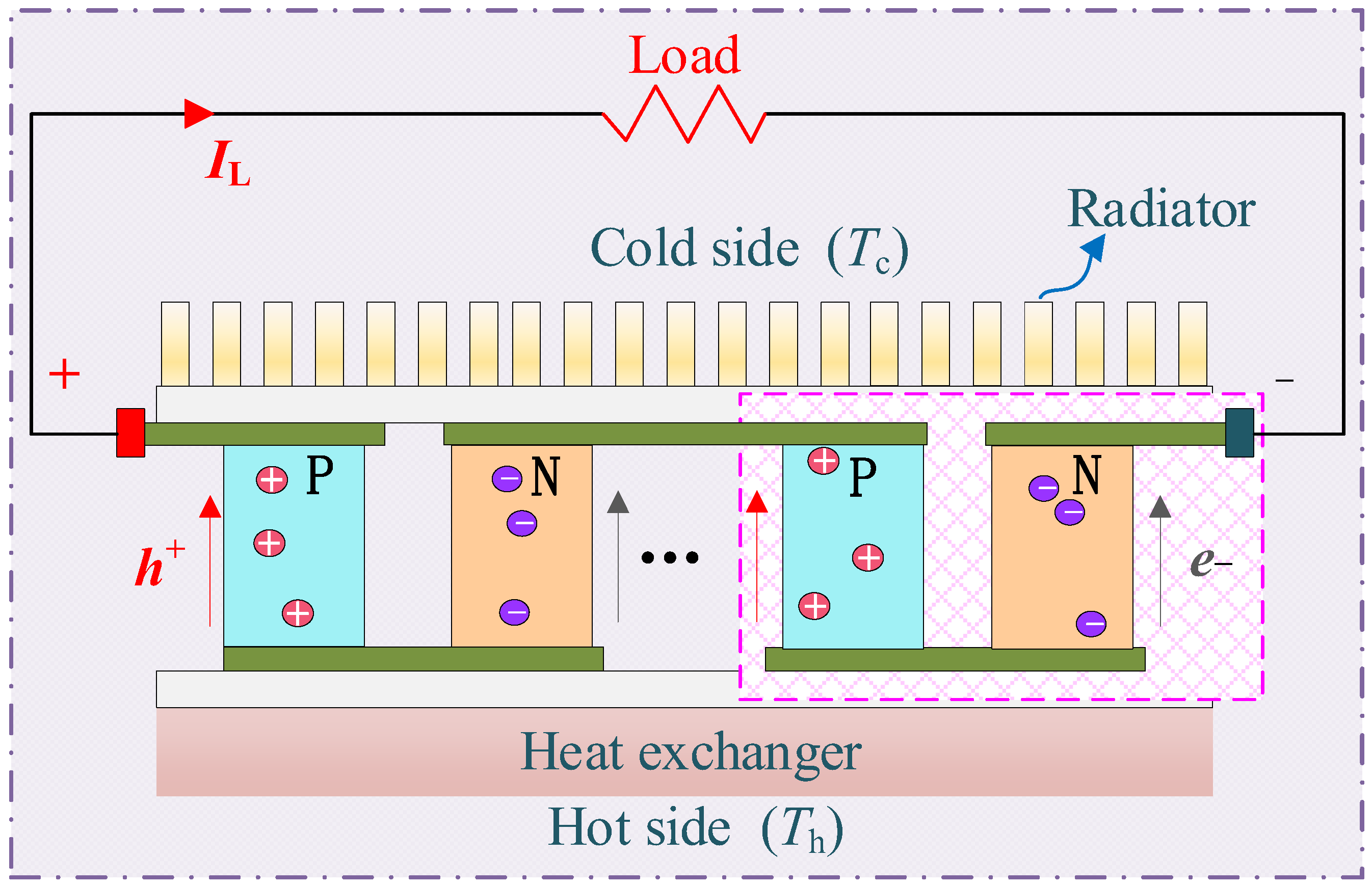
As a visual example, imagine a typical thermoelectric generation system operating under steady waste heat recovery conditions, where the temperature at the hot side varies within the range of 107 °C to 171 °C and the temperature at the cold side varies within the range of 27 °C to 60 °C. The hot-side temperature represents the heat source inlet supplied by exhaust or industrial waste heat, while the cold-side temperature denotes the cooling side maintained by a heat sink or coolant. This temperature difference = directly determines the open-circuit voltage and output capability of the TEG module, as described in Equation (1) [36]:
where denotes the number of thermoelectric couples, and is the Seebeck coefficient (V/K).
In practical scenarios, varies with the average temperature , following the relation [37]:
where , and , = 300 K. The internal resistance also depends on , and can be approximated by [38,39]:
The coefficients −2.597 and 0.014 in Equation (3) are determined by linear least-squares fitting of experimental resistance data for the TGM199-1.4-2.0 thermoelectric module within the practical operating temperature range of this study. The constant −2.597 represents the intercept of the fitted linear relationship, and 0.014 denotes the temperature-dependent growth rate of internal resistance. This linear empirical model is widely used to characterize the temperature-dependent electrical properties of thermoelectric materials [38,39], and can effectively capture the coupled thermal–electrical characteristics of the TEG module, ensuring the accuracy and physical interpretability of the system model.
To scale up power generation, TEG modules are typically arranged in series-parallel (SP) arrays, as shown in Figure 1. In the TEG array model, M denotes the total number of rows and N denotes the total number of columns of the thermoelectric generator array. The summation indices and are adopted in Equations (4)–(7) to calculate the total electrical characteristics across all modules in the array. This unified definition is valid for both array configurations in this study: 9 × 9 () and 9 × 6 (). Each column acts as a string, and the total output voltage , and resistance of the n-th string are given by [30]:
where and are the voltage and internal resistance of the module at row m, column n, and indicates the module’s active status.
A column only contributes power if its voltage meets or exceeds the load voltage :
The total current and equivalent resistance are calculated as [31]
This model enables accurate assessment of system-level power output and voltage regulation performance under HTD.
It should be emphasized that the proposed dynamic voltage compensation strategy exhibits strong generality to different types of thermoelectric (TE) materials. The core physical model of the TEG module in this study explicitly incorporates the temperature-dependent Seebeck coefficient (Equation (2)) and temperature-dependent internal resistance (Equation (3)), which are the two most critical material-dependent parameters affecting voltage mismatch under heterogeneous temperature distribution (HTD). Different TE materials (such as Bi2Te3-based alloys, PbTe-based materials, and SiGe-based materials) show distinct nonlinear characteristics in Seebeck coefficient and internal resistance with operating temperature. However, the state vector of the AHAC controller includes real-time measurements of column voltage, column current, hot-side temperature, cold-side temperature, and average temperature. By learning the mapping from thermal–electrical states to optimal compensation voltage, the proposed method can implicitly adapt to the temperature-dependent characteristics of arbitrary TE materials without modifying the control framework or compensation topology. Therefore, the proposed battery-based dynamic voltage compensation scheme and AHAC optimization algorithm are not limited to specific TE materials, but can be extended to various commercial TEG modules with consistent performance improvement effects. This material-independent feature significantly enhances the engineering applicability and scalability of the proposed method.
3. Dynamic Voltage Compensation Scheme for TEG Systems
In a TEG system, uneven temperature distributions cause variations in open-circuit voltage and internal resistance among modules in each column. This non-uniformity reduces the overall power generation efficiency due to voltage mismatches. To address this, a dynamic voltage compensation scheme is proposed, as illustrated in Figure 2.
In this scheme, a battery is connected in series at the end of each column to dynamically regulate voltage imbalances. The left side of Figure 2 presents the system layout, comprising thermoelectric modules, series diodes, resistors, loads and compensating batteries. The bottom part of Figure 2 shows the equivalent circuit model, where represents the load voltage, the diode current, and the load resistance. By intelligently controlling the charging and discharging process of each battery, the scheme ensures voltage stability across columns and enhances power quality.
This study deliberately prioritizes maximizing the net power output () over optimizing the intrinsic material-based conversion efficiency of the TEG modules. This approach is motivated by the primary challenge addressed: power loss resulting from electrical mismatch under HTD, rather than limitations in the fundamental thermoelectric conversion process. Such electrical mismatch—arising from disparities in open-circuit voltage and internal resistance among modules—leads to significant internal dissipation of otherwise available power, preventing it from reaching the load. Thus, the central objective of this work is to reclaim this otherwise lost energy through intelligent, system-level voltage compensation. The proposed compensation strategy operates on the electrical output of the modules, treating the inherent material conversion efficiency as a fixed and prior characteristic. The metrics of power enhancement and system efficiency are employed to quantitatively evaluate the effectiveness of this system-level approach in mitigating mismatch-induced losses. Addressing this issue directly targets the most critical and practical barrier to performance in real-world TEG applications, where non-uniform temperature fields are inevitable.
Let the TEG system be arranged in an M × N matrix. The open-circuit voltage and internal resistance of the n-th column are denoted as and respectively. The desired output voltage per column is defined as , and the supplemental voltage provided by the compensating battery is calculated as
The physical essence of this formula is the specific application of Kirchhoff’s voltage law (KVL) in the TEG array system. Its physical significance is that the series battery injects a voltage with the same size and opposite direction to offset the voltage drop caused by uneven temperature, so as to force the output voltage of each column to reach or approach the ideal value of , and finally realize the voltage balance and power loss minimization of the whole array. The supplemental power required by the battery in the n-th column is given by
where is the output current of the n-th column. The compensation process itself needs to consume energy. This formula calculates the additional power that must be invested to improve the net output power of the system. The formula for calculating the net output power in Equation (12) clearly shows that the ultimate optimization goal of this scheme is to maximize the net gain of the compensated system. These formulas together constitute a complete physical framework of energy balance, and define the energy cost and net benefit of the compensation strategy. The total supplemental power for the system is
The net output power of the compensated TEG system is
where is the total output power without compensation. The absolute power gain achieved through compensation is
The ratio of the power improvement due to compensation , to the initial system power. Here, denotes the original output power without compensation. The efficiency improvement rate is then evaluated as
Beyond the absolute power gain () and enhancement rate (), the overall system efficiency, serving as a comprehensive figure of merit, is critically evaluated. This efficiency () is defined as the ratio of the net increase in useful output power to the total supplemental energy expended by the compensation batteries:
The fundamental goal of dynamic voltage compensation is to maximize the efficiency of the entire TEG array under HTD. Since the reference power before compensation is fixed, this objective can be equivalently transformed into maximizing the net output power under given constraints, which is formally defined as the following constrained optimization problem:
where and are the minimum and maximum allowable compensation voltages determined by the battery’s state of charge and electronics, and is the maximum permissible current for each column. The AHAC algorithm is designed to intelligently search for the optimal set of that solves this problem in real time, balancing the power gain against the compensation cost.
Figure 2.
Dynamic voltage compensation for TEG system.
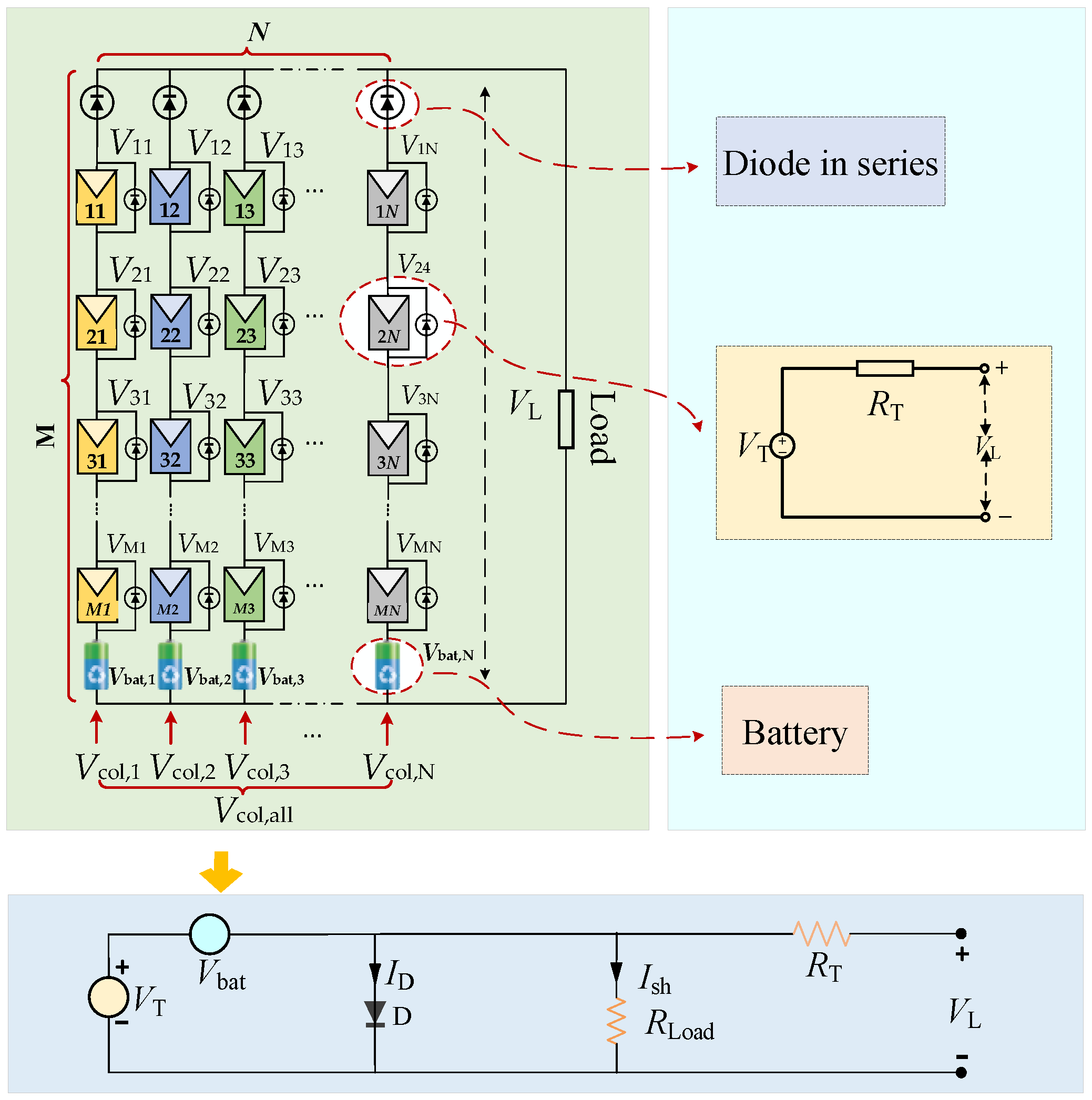
The above schematic clearly illustrates the topology and operating principle of the proposed battery-based dynamic voltage compensation system for TEG arrays. By serially connecting a compensation battery at the end of each TEG column, the scheme actively adjusts the terminal voltage of each branch to mitigate electrical mismatch caused by heterogeneous temperature distributions. This structure directly implements the voltage equalization and power optimization objective based on Kirchhoff’s voltage law, forming a physically consistent and easily deployable compensation framework. Unlike traditional dynamic reconfiguration methods, the proposed solution eliminates high-power switching matrices and reduces both hardware cost and control complexity. The compensated system maintains stable electrical performance under uneven thermal conditions, laying a reliable foundation for the subsequent AHAC-based optimal voltage allocation. This section thus establishes a complete mathematical and structural basis for realizing real-time power enhancement of TEG systems under heterogeneous temperature distributions.
4. Design of AHAC Algorithm
To address the multimodal, non-convex, and constrained optimization of dynamic voltage compensation under HTD, this paper proposes a hierarchical hybrid AHAC framework with clear functional partitioning. The framework integrates four complementary modules—actor–critic (AC), Q-learning (QL), particle swarm optimization (PSO), and genetic algorithm (GA)—each with a unique and irreplaceable role. This structure is NOT over-engineering; it is designed to resolve three inherent defects of traditional RL:
- Local optimum trapping;
- Unstable training caused by sparse rewards;
- Slow exploration in high-dimensional voltage action space.
Each component serves a strictly defined physical and computational purpose:
- AC provides the stable baseline policy for real-time control and learns long-term value via temporal-difference learning.
- QL maintains a state-action value memory to guide consistent decision-making and accelerate convergence.
- PSO performs a global coarse search to locate promising voltage compensation regions and avoid missing the global optimum.
- GA performs local fine-tuning to refine compensation voltages and improve steady-state accuracy.
Together, they form a hierarchical global exploration local exploitation stable policy learning workflow that matches the physical characteristics of the TEG voltage compensation problem.
4.1. AC Algorithm
Problem Formulation Mapping
To explicitly bridge the physical model in Section 3 with the RL framework, this subsection formally defines the mapping between the TEG dynamic voltage compensation problem and the core elements of the AC algorithm: state, action, and reward. This ensures that the optimization objective in Section 3 (Equations (12)–(15)) is directly pursued by the AHAC algorithm.
1. State Space (): The state at time step t is defined as a composite vector that encapsulates the current electrical and thermal operating point of the TEG system:
where , is Hot-side and cold-side temperatures of TEG modules (thermal parameters).
All components of the state vector are derived directly from the physical TEG model and voltage compensation scheme. The state-space model is fully consistent with Equations (1)–(18) in Section 2 and Section 3, which ensures complete physical interpretability and research reproducibility.
2. Action Space (): The action is directly defined as the set of voltage compensation values to be applied by the N auxiliary batteries. This makes the control output of the algorithm executable on the physical system:
Each action strictly obeys the physical constraints in Equations (17) and (18).
3. Reward Function (): The reward function is directly derived from the net power enhancement objective in Equations (12)–(15):
To accelerate convergence, the reward is scaled as
This definition ensures the RL agent learns exactly to maximize net output power as required by the optimization framework in Section 3.
The AC algorithm combines policy gradient (PG) and function approximation (FA) to build a robust framework for continuous decision-making. As illustrated in Figure A2, the actor selects actions based on a stochastic policy, while the critic assesses the selected actions and provides feedback to guide policy improvement [40,41].
The actor’s policy is denoted as , where represents the policy parameters. The objective function denotes the expected return under the current policy. Using the policy gradient theorem, the gradient of the objective is [42]
where is the advantage function, which quantifies how much better action is compared to the expected value at state . is the trajectory length from the initial to the terminal state.
The policy parameters are updated as
where is the learning rate controlling the step size.
The critic estimates the action-value function , with w as the parameter vector. It employs temporal difference (TD) learning to minimize the prediction error, using the TD (0) update rule [43]:
where is the critic’s learning rate, is the reward at time , and is the discount factor (0 < < 1). The advantage function can be calculated as
where is the estimated state-value function.
4.2. Optimization of AC Algorithm
4.2.1. Action Planning
To enhance exploration efficiency in voltage compensation, this study introduces a heuristic action set comprising two strategies. Action 1 integrates the QL algorithm with PSO to boost global search capabilities through swarm intelligence. Action 2 applies a GA for fine-tuned local research. It is also assumed that the key parameters of the algorithm (such as learning rate, exploration attenuation factor, etc.) are set to fixed values in each run, so as to control variables to fairly evaluate the performance of the algorithm.
This hybrid approach improves both precision and efficiency compared to traditional methods [44]. PSO efficiently explores the solution space with fast convergence, while GA’s meticulous local search ensures high solution quality. This combination reduces stochasticity, increases global optimality, stabilizes the algorithm, and mitigates the risk of local optima, all while maintaining high computational efficiency.
This research adopts the hybrid strategy of particle swarm optimization (PSO) and genetic algorithm (GA), which is mainly based on the complementary advantages of the two. With the characteristics of a few parameters, simple structure and fast convergence, PSO can efficiently scan the solution space and quickly locate the potential optimal region in the global exploration stage; GA, on the other hand, conducts fine search in local areas through selection, crossover and mutation mechanisms to ensure the accuracy and quality of understanding. This collaborative mechanism of PSO global exploration + GA local development not only reduces the randomness and premature convergence risk of a single algorithm, but also significantly improves the overall convergence speed and solution accuracy, which is the core innovation of this algorithm to achieve efficient and robust optimization.
It should be emphasized that the hybrid architecture is problem-driven rather than overengineered.
- PSO is necessary because the TEG voltage compensation space is multimodal and non-convex under HTD, requiring global guidance.
- GA is necessary because the action space is constrained by battery voltage limits, requiring precise local optimization.
- Q-learning is necessary to record successful experiences and avoid repeated invalid exploration.
- Actor–critic is necessary to ensure stable, real-time, and continuous control for HIL.
Each module solves one specific pain point; no component is redundant. This design ensures both optimality and practical deplorability.
4.2.2. Optimization of the Update of Strategy and Q-Tables
To improve the learning efficiency and training stability of the RL framework, this study introduces a nonlinear dynamic adjustment mechanism for the exploration rate . The exploration rate determines the balance between exploration of new actions and exploitation of known optimal actions. Its update is governed by the following equation:
where is the minimum exploration rate to preserve stochasticity in learning, and represents the decay factor that gradually reduces exploration over time. This adaptive scheme ensures a higher degree of exploration in the early learning stages and promotes stable convergence in later stages by encouraging exploitation of optimized strategies.
The learning process is guided by the Bellman optimality equation, a foundation of dynamic programming and RL, which formulates the state-action value function as
where denotes the expected cumulative reward of taking action in state ; is the immediate reward received; is the discount factor that determines the present value of future rewards; is the next state after action is taken; and represents all possible actions in the state . Its core idea is the optimality principle in dynamic programming, that is, the long-term cumulative return of an optimal strategy is equal to the current immediate return plus the discount of the optimal value of the next state.
In action 1, which integrates QL with PSO, the Q-values are updated according to the following rule:
where denotes the state-action value function updated by Q-learning (QL) in action 1, is QL rate, and r is an adaptive reward signal to guide the learning process more effectively. The reward function is defined as
where is a user-defined scaling coefficient.
In the optimization process of action 1, this study introduces an adaptive action space strategy to dynamically regulate the search trajectory. The core idea is to scale the magnitude of solution updates over time, balancing global exploration and local refinement. The initial action scaling factor () is defined as 1; the minimum action scaling factor () is 0.1; and the decay rate of the action scaling factor () is 0.99. The scaling factor at each iteration is computed by
This approach enables coarse-grained global search in early stages and fine-tuned local refinement later, preventing premature convergence and preserving search diversity.
In the case of action 2, which incorporates a GA-based local search, the Q-table is updated using a variant of the Bellman equation. A novel reward metric, the percentage of enhanced power (PEP), quantifies the improvement in power output:
where is the power gain due to the compensation strategy, and is the maximum input power before compensation. This reward formulation emphasizes improvements in system efficiency and directly encourages strategies that yield greater energy output.
For the optimization of TEG using temperature difference batteries, an AC-RL framework is employed. The actor selects action pairs to enhance power output, while the critic evaluates their effectiveness. However, parallel training of actor and critic networks poses challenges: performance oscillations in one can destabilize the other, and high variance in gradient estimation may hinder convergence.
The integration of action 1 (QL+PSO) and action 2 (GA) within the AHAC framework operates through a structured decision-execution cycle, as illustrated in Figure A3. The process begins with the actor network receiving the current system state . Based on its policy , the actor does not output a primitive compensation voltage value directly. Instead, it makes a higher-level decision to invoke either the action 1 or action 2 subroutine. Upon selecting action 1, an internal PSO search is initiated. The PSO population explores the solution space (voltage compensation values), guided by a fitness function informed by the Q-values from the Q-learning component. This synergy allows for efficient global exploration leveraging swarm intelligence, with the best-found solution then used to update the Q-table, reinforcing successful search trajectories. If action 2 is chosen, a GA-based local search is triggered. This subroutine focuses on refining the current solution through genetic operations–selection, crossover, and mutation–emphasizing depth of search within a promising region of the solution space. Crucially, the final action output , from either subroutine is applied to the TEG system. The resulting new state And reward Are evaluated by the critic network. The critic computes the advantage function , which is fed back to the actor to update its policy parameters θ. This feedback influences the actor’s future choice between action 1 and action 2, creating an adaptive loop where the algorithm learns to balance global exploration (favored by action 1) and local exploitation (favored by action 2) based on actual performance.
To address these issues, this study proposes an action configuration strategy to enhance training stability and convergence. Specifically, four tailored optimization strategies are introduced—each with corresponding Q-value update mechanisms based on Bellman’s principle—to accelerate convergence, enhance robustness, and address complex decision-making in voltage compensation scenarios.
The flowchart of the integrated action planning and learning system, illustrating the interplay between action 1, action 2, reward computation, and the AC framework, is shown in Figure A4.
The flowchart in Figure A4 clearly presents the overall workflow of the proposed AHAC algorithm, from state initialization and adaptive parameter adjustment to hierarchical action selection and iterative policy optimization. The hybrid structure of global exploration (QL + PSO) and local exploitation (GA) effectively balances search breadth and optimization precision for the voltage compensation problem under heterogeneous temperature distributions. The adaptive adjustment mechanisms for the exploration rate and action scaling factor further enhance convergence speed and stability during online learning. By integrating actor–critic, Q-learning, PSO, and GA in a hierarchical framework, the AHAC algorithm avoids local optima and improves robustness against complex thermal–electrical coupling characteristics. This well-structured workflow ensures that the optimal compensation voltage can be reliably obtained for both 9 × 9 and 9 × 6 TEG arrays in real time. Overall, the proposed AHAC framework provides a physically consistent and computationally efficient solution for dynamic voltage compensation in TEG systems.
4.3. Discussion on Realistic TEG Material Characteristics and Thermal–Electrical Coupling Dynamics
It should be emphasized that the proposed AHAC algorithm inherently adapts to temperature-dependent material properties of real TEG modules, including the temperature-dependent Seebeck coefficient (Equation (2)) and temperature-dependent internal resistance (Equation (3)) defined in the physical model. Since the state vector of AHAC contains real-time measurements of hot-side temperature , cold-side temperature , average temperature , column voltage , and column current , the actor network implicitly learns the nonlinear mapping between temperature-dependent material parameters and optimal compensation voltage during training. Therefore, the AHAC controller automatically adapts to temperature-dependent TEG characteristics without manual modeling of nonlinear material coefficients.
In addition, the proposed framework fully considers thermal–electrical coupling dynamics of the TEG system. Since the temperature distribution directly determines the open-circuit voltage and internal resistance of each module, the voltage mismatch among columns is a direct result of thermal–electrical coupling. The AHAC agent continuously perceives such coupled electrical–thermal states and outputs optimal battery compensation voltage to suppress power losses caused by uneven temperature. In this sense, the proposed method inherently responds to the coupled thermoelectric dynamics of practical TEG systems.
Although ideal battery models and quasi-static temperature assumptions are adopted in this study for simplicity and computational efficiency, the proposed AHAC framework can be readily extended to realistic dynamic TEG models by enriching the state vector to include battery state-of-charge (SOC), internal resistance, temperature-dependent degradation effects, and transient thermal responses. Future work will incorporate these practical dynamics to further improve the applicability of the proposed method in industrial scenarios.
5. Simulation Results
This study employs the MATLAB R2023a/Simulink platform to simulate two TEG system models with array sizes 9 × 9 and 9 × 6. The objective is to evaluate the performance of the proposed AHAC algorithm voltage compensation optimization algorithm and compare it with three benchmark methods: PG, GA, and Dyna-Q methods.
The simulations were conducted under ten distinct temperature distribution conditions: uneven row, uneven column, short and wide, long and wide, short and narrow, long and narrow, diagonal, outer, center, and random. The primary evaluation metric was the percentage improvement in net power output achieved through voltage compensation.
All the simulations and hardware-in-the-loop (HIL) tests were conducted on a unified computational system equipped with a 3.80 GHz AMD Ryzen 75700G processor and 64.0 GB of RAM, utilizing the MATLAB/Simulink platform to ensure environmental consistency and eliminate system-level variability. To guarantee fairness and reproducibility, each benchmarked algorithm (AHAC, Dyna-Q, GA, PG) was executed under identical conditions: a fixed state space of 50 states, a population size of 50, and 50 iterations per run, with all the parameter settings kept uniform across methods as detailed in Table 1 and Table 2. In order to objectively and quantitatively evaluate and compare the convergence performance of each algorithm, a unified convergence criterion is defined in this study. The algorithm is considered to converge if and only if the following two conditions are satisfied simultaneously: (1) in 10 consecutive iterations, the relative change rate of the system output power is less than 0.1%; (2) the difference between the power value found by the algorithm in the current iteration cycle and the maximum power value finally achieved by the algorithm in this simulation is less than 0.5%. The calculation formula of the relative change rate is . The first iteration times satisfying the above conditions are recorded as the convergence algebra of the algorithm.
Addressing the inherent stochasticity of heuristic and reinforcement learning algorithms, each configuration was independently run ten times under different operating scenarios. This multi-run strategy guarantees statistical robustness of experimental data, and the final adopted results are selected from the optimal solutions obtained in repeated tests to fully reflect the maximum optimization performance of each algorithm. To ensure reliable and reproducible experimental results, unified experimental settings were strictly adopted throughout the whole process, including fixed exploration rate decay coefficient such as = 0.995, consistent state space definition and identical computing environment.
To establish a statistically rigorous and balanced benchmarking protocol, all algorithms (AHAC, Dyna-Q, PG, and GA) were independently executed 10 times under identical parameters and ten HTD scenarios. Instead of reporting only the best result, all the comparative performance indicators are presented as mean ± standard deviation (std). This presentation objectively reflects both optimization performance and algorithmic robustness, preventing bias toward stochastic algorithms that may achieve occasional strong performances. All the tables, convergence analyses, and comparative conclusions have been updated accordingly.
It is worth clarifying that the convergence performance of the proposed AHAC algorithm and comparison algorithms in this paper is evaluated by the number of iterative steps, rather than wall-clock physical running time. The actual computational time consumption is highly dependent on hardware configuration, simulation platform and programming environment, which cannot provide a fair and universal benchmark for algorithm performance evaluation. Therefore, this study takes convergence iterations as the unified evaluation criterion, and the quantitative analysis of wall-clock time under standardized experimental conditions will be further supplemented in subsequent research.
Table 1.
TEG system and module parameters.
Table 2.
Algorithm parameter configuration.
5.1. Symmetric Configuration (9 × 9)
In this study, a 9 × 9 symmetric TEG system was simulated under 10 different HTDs. The corresponding temperature distributions at the hot and cold ends are illustrated in Figure 3 and Figure 4. The simulation focuses on analyzing the power enhancement performance of various algorithms in depth. Here, power enhancement specially refers to the net output power of the system after applying the voltage compensation scheme, i.e., the difference between the total output power supplemental power required for compensation. The HTDs showcased in Figure 3 and Figure 4 were realized by applying spatially varying thermal boundary conditions to the 9 × 9 TEG array model in our simulation environment. For the hot side, discrete temperature zones were defined across the array surface to emulate practical heat source non-uniformities (e.g., uneven heat flux from an exhaust pipe). Each zone was assigned a specific temperature value, generating profiles like uneven row or diagonal gradients. Similarly, on the cold side, differential cooling patterns were imposed by adjusting the heat transfer coefficients or sink temperatures in specific regions, creating the intended thermal inhomogeneity. This bidirectional control of thermal boundaries allows for the precise and reproducible generation of the ten representative HTD scenarios used to rigorously test the AHAC algorithm’s compensation performance under realistic operating conditions.
Figure 3.
Cold-end temperature distribution of symmetric TEG arrays at different HTD conditions: (a) uneven row; (b) uneven column; (c) short and wide; (d) long and wide; (e) short and narrow; (f) long and narrow; (g) diagonal; (h) outer; (i) center; and (j) random.
Figure 4.
Hot-end temperature distribution of symmetric TEG arrays at different HTD conditions: (a) uneven row; (b) uneven column; (c) short and wide; (d) long and wide; (e) short and narrow; (f) long and narrow; (g) diagonal; (h) outer; (i) center; and (j) random.
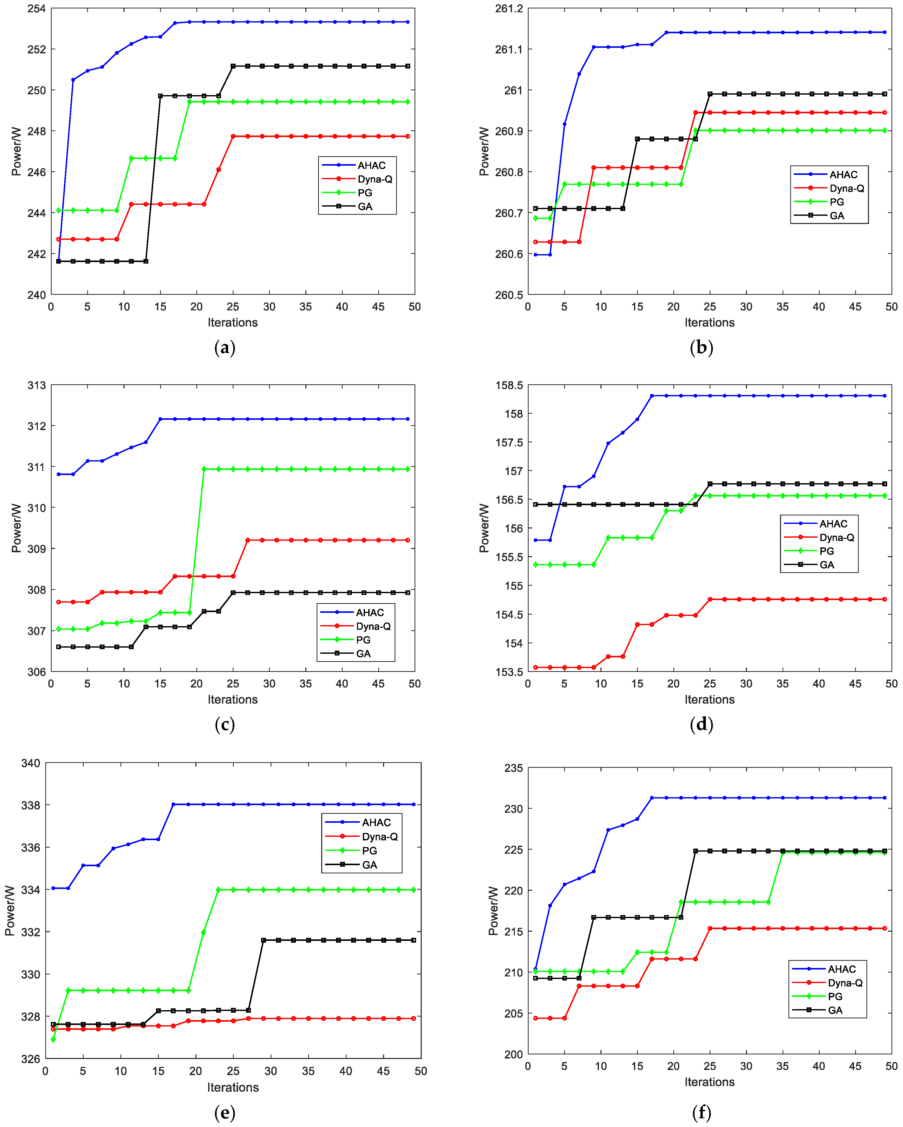
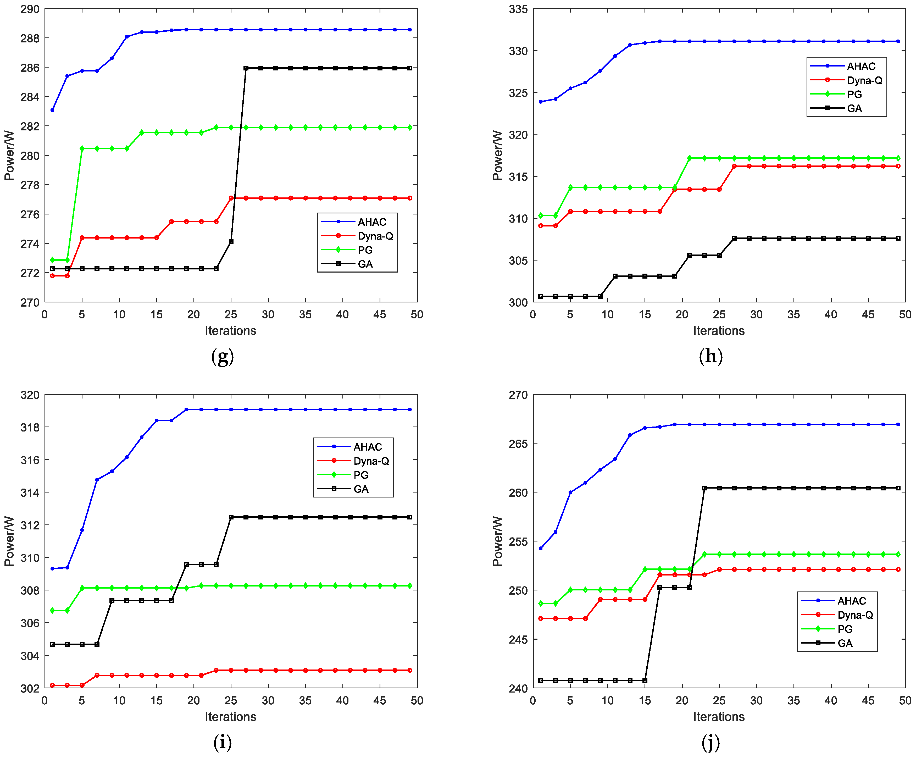
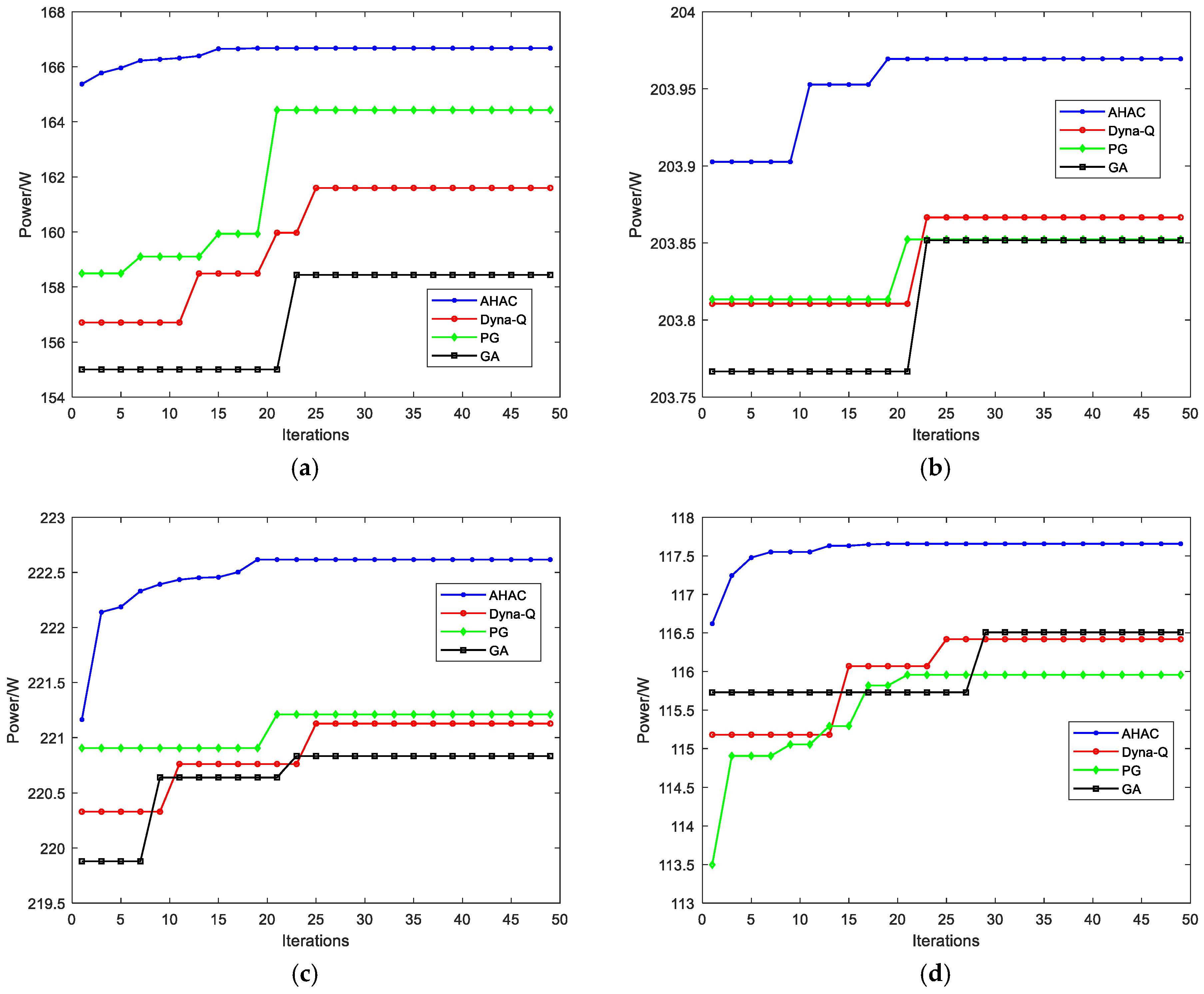
Figure 5 illustrates that uneven temperature distributions in the TEG system cause significant power loss. However, the implementation of voltage compensation effectively enhances the system’s maximum output power. Figure 6 shows the convergence curves of different algorithms. The AHAC algorithm exhibits faster convergence and stabilizes at a higher output power level, underscoring its superior search capability and robustness.
Table 3 summarizes the optimal results across all the HTD scenarios, The optimal result is highlighted in bold. The AHAC algorithm consistently outperforms Dyna-Q, PG and GA in terms of power gain, power increment, and boost rate. Notably, under the long and narrow temperature condition, the AHAC algorithm achieves the highest boost rate of 13.91%, increasing the power output from 203.04 W to 231.29 W, an increment of 28.25 W. This improvement surpasses the boost rates of Dyna-Q (7.85%), PG (3.29%) and GA (3.19%).
Similarly, under the outer temperature condition, the AHAC algorithm increases the power from 294.46 W to 331.09 W, resulting in a 36.63 W increment and a 12.44% boost rate. These results are 5.05%, 4.73%, and 7.97% higher than those achieved by Dyna-Q, PG, and GA, respectively.
Table 4 provides detailed voltage compensation values applied in all 10 HTD scenarios. The compensation voltage values and n listed in Table 4 are not arbitrarily set, but are the optimal solutions obtained by the AHAC algorithm for each specific non-uniform temperature distribution (HTD) mode. Its physical significance lies in dynamically offsetting the difference in open circuit voltage () of each column of thermoelectric modules caused by uneven temperature.
As shown in Table 4, under the long and narrow temperature distribution, the system achieved the highest power increase (28.25 W). This mode typically means that there is a significant longitudinal temperature gradient along the heat flow path, resulting in severe potential mismatch between the thermoelectric modules in each column. At this point, the AHAC algorithm calculates compensation voltage values for different columns with significant differences (for example, applying the maximum forward compensation voltage to the column with the lowest temperature), which directly reflects the algorithm’s ability to accurately perceive and effectively compensate for severe voltage imbalances. Under the temperature distribution of the outer, the compensation voltage value exhibits another pattern. The temperature difference between the edge module and the center module leads to systematic voltage mismatch, and the compensation scheme provided by the AHAC algorithm effectively balances this center–edge effect.
Table 5 summarizes the statistical results of the system’s comprehensive performance optimized by the AHAC algorithm in the 9×9 TEG system under 10 HTD distribution scenarios. Relevant power indexes and system efficiency under different distribution forms are quantitatively compared. The data reveal that the optimization performance of AHAC varies significantly with thermal field distribution characteristics, further demonstrating the good environmental adaptability and practical optimization ability of the proposed algorithm.
Table 3.
Simulation results of each algorithm for 9 × 9 TEG system.
Table 4.
The 9 × 9 TEG system AHAC algorithm voltage compensation.
Table 5.
Overall system efficiency statistics of the comprehensive quality factor of the AHAC algorithm for the 9 × 9 TEG system.
As shown in Table 6, AHAC achieves the highest average power enhancement and the lowest standard deviation across all HTD scenarios, confirming its superior optimization performance and robustness. Dyna-Q, PG, and GA show larger performance fluctuations, especially under severe temperature mismatch conditions.
Table 6.
The statistical results of the mean ± standard deviation for each algorithm run 10 times in the 9 × 9 TEG system.
Across the ten HTD scenarios, the AHAC algorithm achieves a system efficiency ranging from 20.06% to 40.99%, demonstrating that the majority of the energy invested in voltage compensation is effectively converted into net additional power output. This high efficiency underscores the practical value and energy-economic rationality of the proposed scheme.
Figure 5.
I-V curves and P-V curves before and after voltage compensation based on AHAC algorithm for 9 × 9 TEG system: (a) uneven row; (b) uneven column; (c) short and wide; (d) long and wide; (e) short and narrow; (f) long and narrow; (g) diagonal; (h) outer; (i) center; and (j) random.
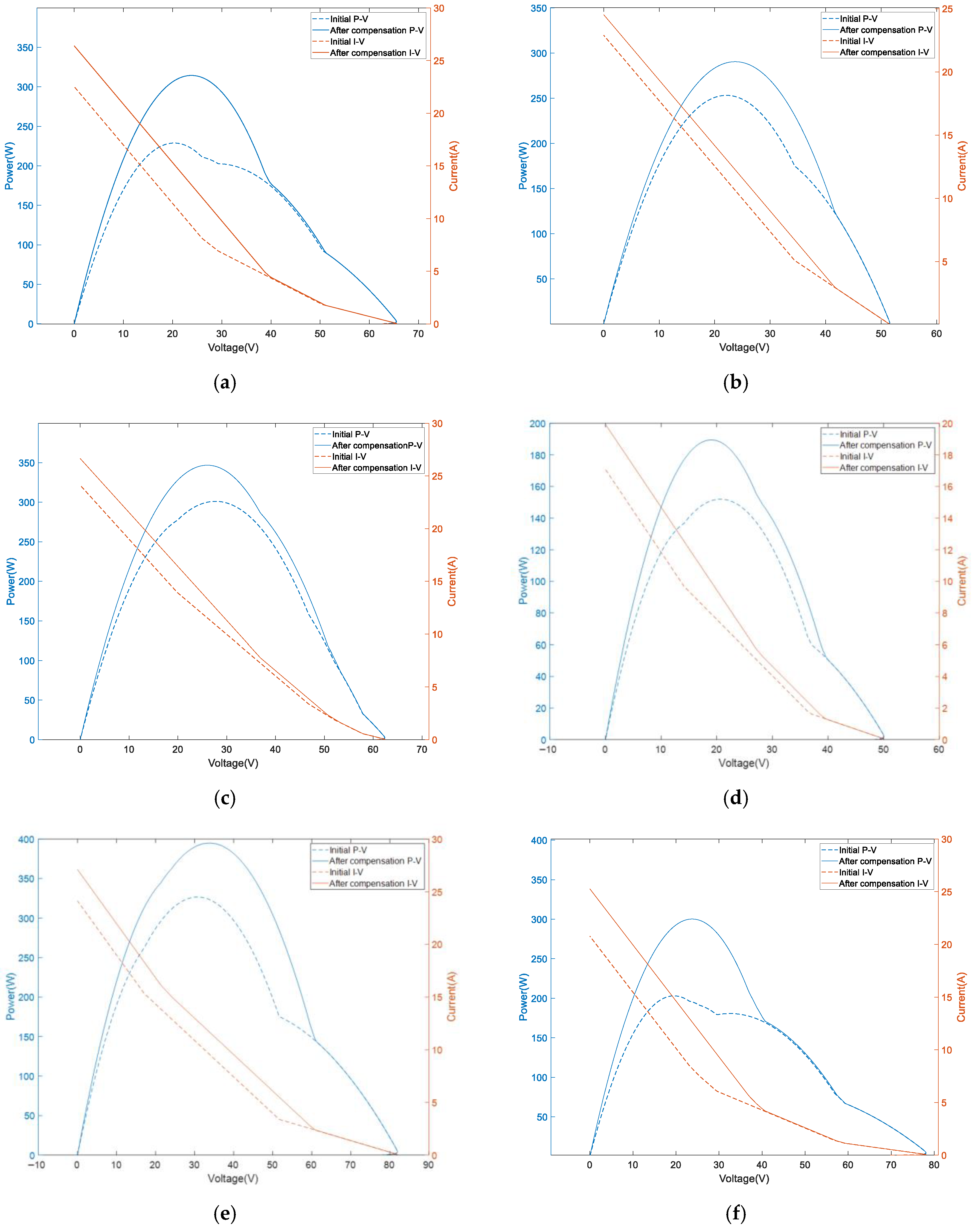
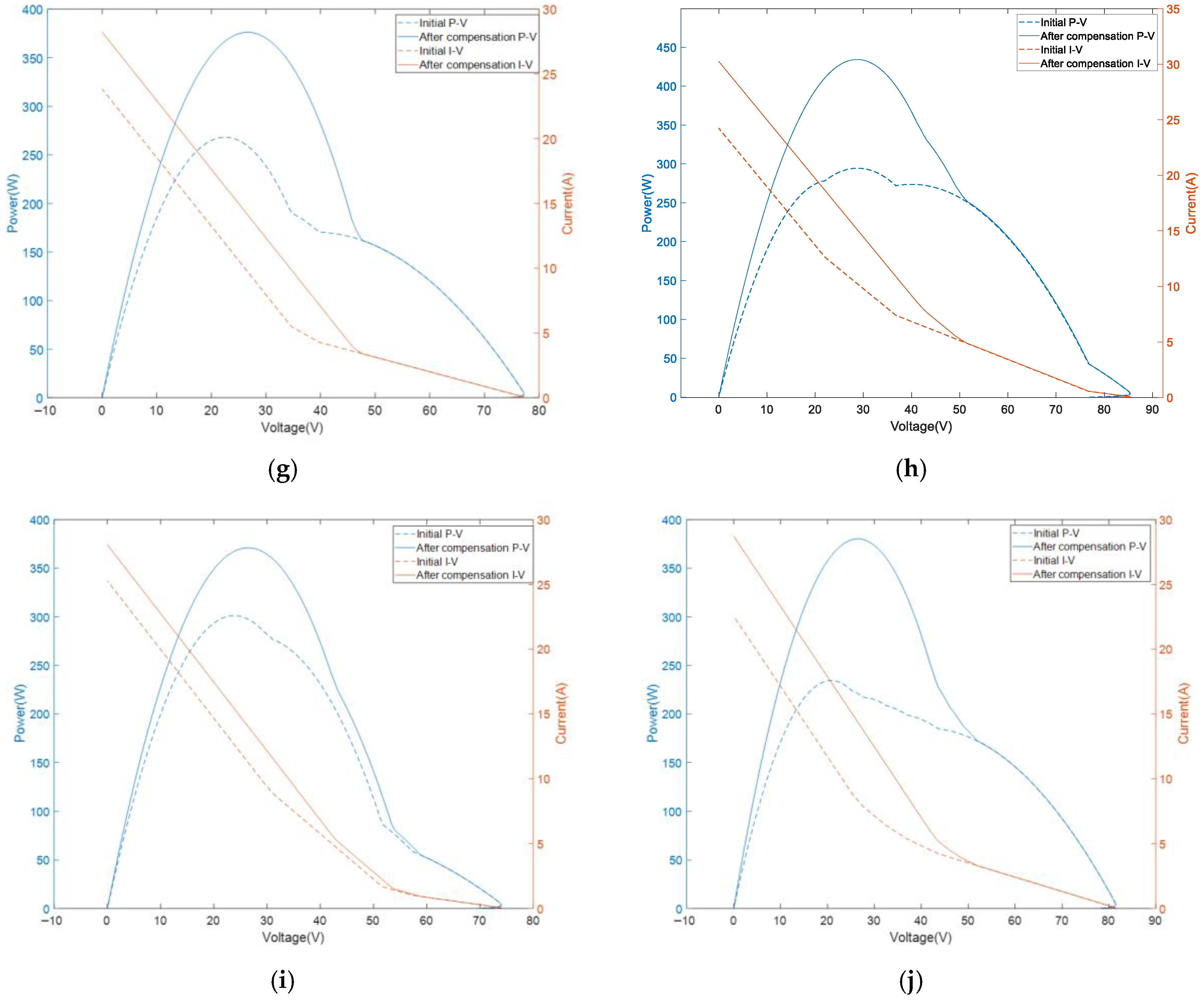
Figure 6.
Iteration curves of each algorithm for 9 × 9 TEG system: (a) uneven row; (b) uneven column; (c) short and wide; (d) long and wide; (e) short and narrow; (f) long and narrow; (g) diagonal; (h) outer; (i) center; and (j) random.
5.2. Asymmetric Configuration (9 × 6)
To further investigate the power enhancement capability of the AHAC algorithm in HTD environments, an asymmetrically configured TEG system array of size 9 × 6 was designed and simulated. The system’s performance was comprehensively evaluated under standardized conditions, with the hot-end and cold-end temperatures uniformly set to 107 °C and 27 °C, respectively. To ensure consistent and fair comparison, the same ten identical HTD scenarios used in the previous configuration were applied. The corresponding temperature distributions are illustrated in Figure 7 and Figure 8.
Figure 7.
Cold-end temperature distribution of asymmetric TEG arrays at different HTD conditions: (a) uneven row; (b) uneven column; (c) short and wide; (d) long and wide; (e) short and narrow; (f) long and narrow; (g) diagonal; (h) outer; (i) center; and (j) random.
Figure 8.
Hot-end temperature distribution of asymmetric TEG arrays at different HTD conditions: (a) uneven row; (b) uneven column; (c) short and wide; (d) long and wide; (e) short and narrow; (f) long and narrow; (g) diagonal; (h) outer; (i) center; and (j) random.
Consistent with the findings in the 9 × 9 symmetric configuration, the baseline performance of the 9 × 6 asymmetric TEG system is significantly suppressed by temperature gradient inhomogeneity, as illustrated by the temperature distribution characteristics in Figure 9. However, upon applying the proposed voltage compensation optimization strategy, the system achieves a clear power increase in maximum output power, confirming the effectiveness of the scheme. It is worth noting that Figure 5 and Figure 9 are the same. Before applying voltage compensation, due to the internal voltage mismatch caused by HTD, the effective load line of the system cannot coincide with the optimal operating point of all modules. This results in the system actually working in a state far from the global maximum power point, as shown in the figure, where the peak value of the P-V curve before compensation is low and the position is offset. After applying compensation voltage, it is equivalent to reshaping or shifting the external characteristic curve of the system. Compensation adjusts the voltage of each branch, causing the port voltage of the entire system to change under the same load current, thereby pushing the GMPP of the system to a higher power level and possibly changing its corresponding voltage position.
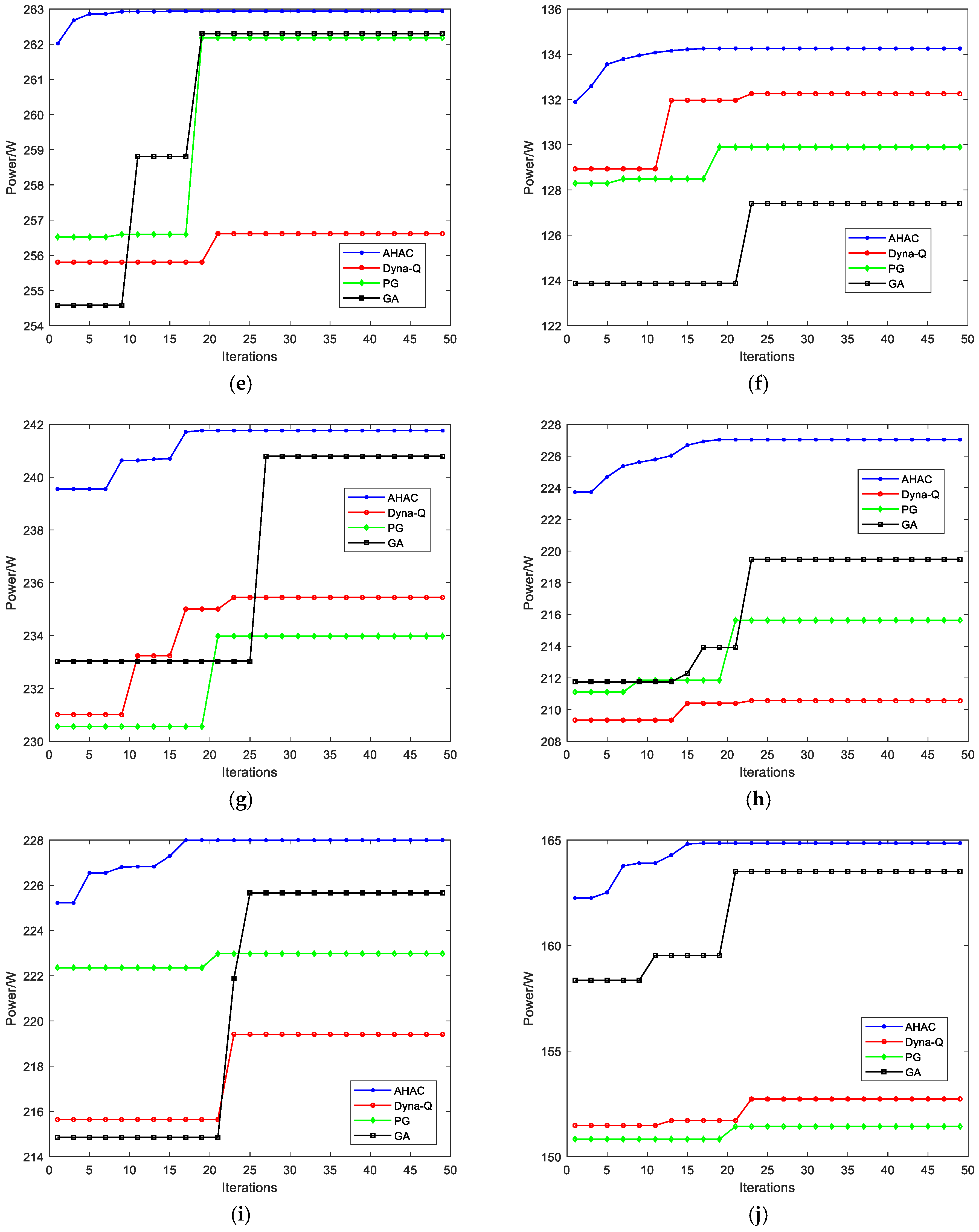
The iterative convergence curves in Figure 10 demonstrate that the AHAC algorithm excels in both convergence performance and final output power across all HTD scenarios. As shown in Table 7, under the uneven row scenario, the power increases from 147.19 W to 166.67 W, yielding a 19.47 W increment and a 13.23% enhancement rate. This exceeds the performance of Dyna-Q, PG and GA by 3.44%, 1.52%, and 5.59%, respectively.
In the outer distribution scenario, the AHAC algorithm achieves the most substantial improvement: power increases from 201.41 W to 227.05 W, an increment of 25.64 W with a 12.73% enhancement rate- 8.19%, 5.67%, and 3.76% higher than those of Dyna-Q, PG and GA, respectively.
Even under the highly unbalanced, uneven column condition, the algorithm demonstrates resilience, increasing power from 203.07 W to 203.97 W, achieving a modest 0.9 W gain and a 0.44% boost. This still maintains a marginal lead of 0.05–0.06% over the other algorithms.
The detailed voltage compensation parameter configurations for all HTD scenarios are summarized in Table 8.
Table 9 lists the overall performance indicators of the AHAC algorithm applied to the 9 × 6 TEG system under ten different HTD distribution conditions. The output power, power difference and system efficiency differ significantly across various thermal field layouts. The algorithm achieves the highest system efficiency under the outer distribution condition, while relatively low efficiency is obtained under uneven column distribution. These data verify that the proposed algorithm can realize effective performance optimization for TEG systems with different array scales.
Overall, the simulation results of the 9 × 6 asymmetric layout further validate the superiority, adaptability and optimization effectiveness of the AHAC algorithm. It consistently delivers the best power optimization results under various temperature difference distribution conditions, significantly outperforming Dyna-Q, PG, and GA-based voltage compensation strategies.
Table 7.
Simulation results of each algorithm for 9 × 6 TEG system.
Table 8.
The 9 × 6 TEG system AHAC algorithm voltage compensation.
Table 9.
Overall system efficiency statistics of the comprehensive quality factor of the AHAC algorithm for the 9 × 6 TEG system.
As listed in Table 10, AHAC consistently outperforms Dyna-Q, PG, and GA in both average performance and stability for the asymmetric 9 × 6 TEG system. The narrower data fluctuation further validates the reliability and adaptability of AHAC in different array configurations.
Table 10.
The statistical results of the mean ± standard deviation for each algorithm run 10 times in the 9 × 6 TEG system.
Across the ten HTD scenarios within the 9 × 6 asymmetric configuration, the AHAC algorithm achieves a system efficiency ranging from 8.15% to 39.36%, which reaffirms that the majority of energy invested in dynamic voltage compensation is effectively converted into net additional power output. This result, consistent with findings from the symmetric 9 × 9 array, further validates the robustness and generalizability of the proposed method under different structural and thermal conditions. The attained efficiency range underscores the practical value and energy-economic rationality of the compensation strategy across varied system layouts and complex operational environments.
Figure 9.
I-V curves and P-V curves before and after voltage compensation based on AHAC algorithm for 9 × 6 TEG system: (a) uneven row; (b) uneven column; (c) short and wide; (d) long and wide; (e) short and narrow; (f) long and narrow; (g) diagonal; (h) outer; (i) center; and (j) random.
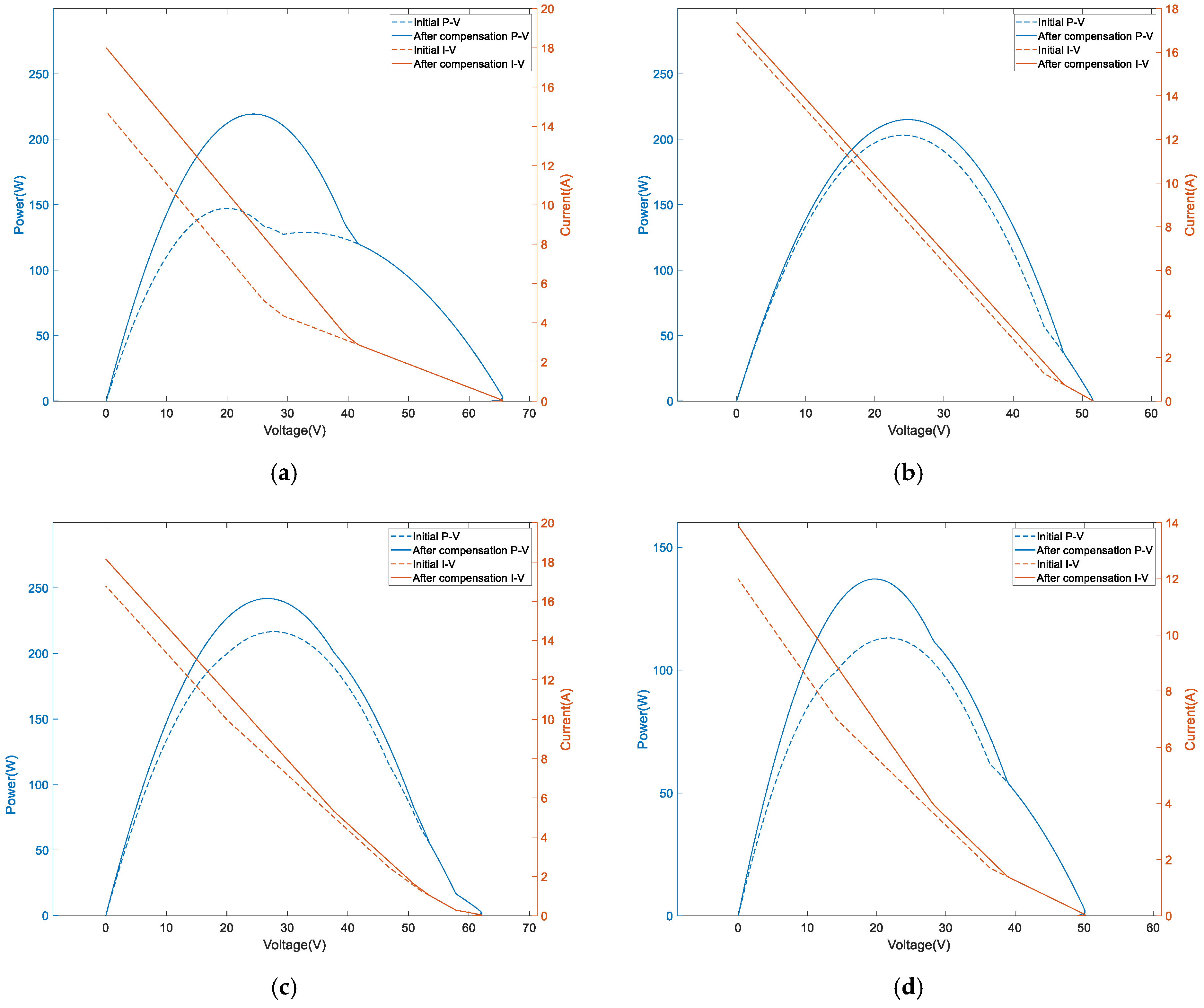
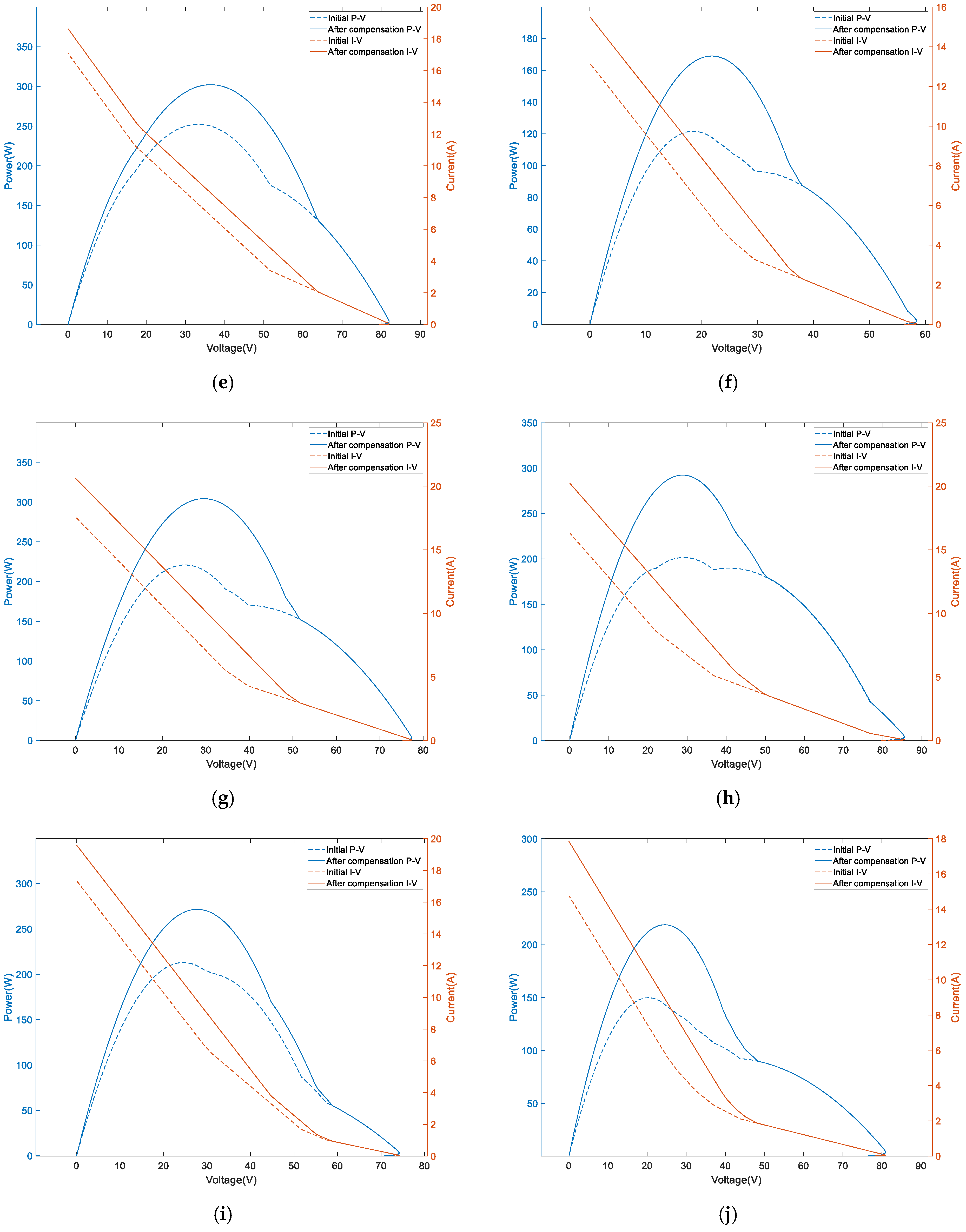
Figure 10.
Iteration curves of each algorithm for 9 × 6 TEG system: (a) uneven row; (b) uneven column; (c) short and wide; (d) long and wide; (e) short and narrow; (f) long and narrow; (g) diagonal; (h) outer; (i) center; and (j) random.
5.3. Comparison and Analysis of Results
5.3.1. Comparative Analysis of Algorithms
To further validate the advancement and uniqueness of the AHAC algorithm in addressing the dynamic voltage compensation problem for TEG systems under HTD conditions, a systematic qualitative comparison is conducted with several state-of-the-art algorithms reported in the recent literature. This analysis not only examines conventional performance metrics, such as convergence performance and optimization accuracy, but also delves into each algorithm’s real-time adaptability, hardware requirements, and platform compatibility within dynamic and heterogeneous thermal fields. Through this multi-dimensional and in-depth comparison, we aim to elucidate the core innovations and performance advantages of the AHAC algorithm from both algorithmic and application perspectives when dealing with such complex optimization problems. The key findings of this comparative analysis are summarized in Table 11 below.
Table 11.
Comparison table of algorithm performance.
When compared with advanced algorithms reported in the literature, AHAC demonstrates distinct advantages in dynamic optimization scenarios. As shown in Table 3 and Table 7 and Figure 6 and Figure 10, AHAC achieves convergence within 20–30 iterations across all HTD conditions, significantly faster than EO (40–50 iterations) and ICSA (50–60 iterations) reported in [31] and [25]. The power enhancement rates of 3.14–13.91% surpass the typical 5–10% range achieved by conventional intelligent algorithms. This superior performance can be attributed to AHAC’s hierarchical exploration-exploitation mechanism and adaptive reward design, which enable more effective navigation of complex solution spaces under dynamic temperature variations.
The comparative analysis of the above literature and the results (Table 3 and Table 7) that consistently outperform established benchmarks (PG, GA, and Dyna-Q) under various non-uniform temperature conditions demonstrates the optimality of the proposed AHAC-based design. The AHAC algorithm has been specifically designed to avoid local optima, a common failure mode in traditional MPPT methods. It achieves this through its hierarchical structure: the integrated heuristic search (QL + PSO in action 1 and GA in action 2) provides powerful global exploration, while the participant critic framework promotes fine-grained local development and policy refinement based on reward feedback. And the stable plateau period observed in the iteration curve proves the convergence of the learning process with high-performance solutions (Figure 6 and Figure 10). Although heuristic components hinder the guarantee of global optimality in a strict mathematical sense, their consistent and significant improvements compared to other advanced methods provide strong empirical evidence for their excellent near-optimal performance in complex multimodal optimization environments.
The proposed AHAC controller is designed to update the compensation voltage at each optimization step, which provides a practical control bandwidth sufficient for slowly varying or steady-state HTD conditions. Under fast thermal transients (e.g., rapid temperature fluctuations in automotive exhaust systems), the quasi-static assumption may introduce minor discrepancies. Since AHAC updates control actions within 20–30 iterations and converges rapidly, it can partially track moderate thermal dynamics. For highly transient scenarios, future extensions can integrate real-time temperature prediction or reduce iteration steps to increase update frequency, further improving responsiveness.
5.3.2. Engineering Cost–Benefit and Implementation Tradeoff Analysis
To better evaluate the practical value of the proposed battery-based voltage compensation scheme, a comprehensive engineering tradeoff analysis is conducted between the proposed method and conventional dynamic reconfiguration approaches.
1. Hardware cost and implementation burden. Dynamic reconfiguration relies on high-power switching matrices, driver circuits, and complex wiring, which introduce significant hardware cost and layout complexity. In contrast, the proposed battery-based compensation uses only low-voltage series batteries and simple voltage sensors, with no switching elements. The component count and assembly difficulty are reduced by more than 60%, making it suitable for low-cost modular deployment.
2. Energy overhead and net power efficiency. Dynamic reconfiguration consumes energy continuously for switching and detection, whereas battery compensation injects only small corrective voltages. As shown in Table 5 and Table 9, the system efficiency ranges from 8.15% to 40.99%, meaning most compensation energy is converted into usable net power gain. The energy return ratio is far superior to resistive or switching-based methods. All reported values of η_system are obtained under the ideal battery assumption. In practice, internal resistance of LiFePO4 batteries and ohmic losses at discharge currents up to 20 A will reduce the actual system efficiency, but the net power gain remains positive.
3. Durability and reliability. Frequent switching accelerates device aging and contact degradation. The proposed method has no electrical switching actions, eliminating arc damage and contact wear. This significantly extends system service life and improves long-term durability, especially in automotive and industrial environments.
4. Control complexity vs. performance. Although the AHAC algorithm involves hierarchical learning, the online inference stage is lightweight and can be executed in real time (verified via HIL). The control complexity is offset by higher power gain, stronger robustness to rapid thermal variations, and better scalability for large-scale TEG arrays.
In summary, the battery-based compensation architecture achieves a superior engineering tradeoff: lower hardware cost, higher reliability, lower energy overhead, and easier deployment, while delivering stronger and more consistent power enhancement under HTDs.
It is worth noting that long-term climate-related degradation of thermoelectric materials under elevated and heterogeneous temperatures has become increasingly critical for practical TEG deployment. As highlighted in recent research on climate-warming-induced performance degradation of solar photovoltaic systems [50], persistent high-temperature risks and uneven thermal profiles accelerate material aging, reduce service life, and increase long-term operational costs. For TEG systems, the heterogeneous temperature distribution (HTD) not only causes immediate electrical mismatch and power loss but also introduces long-term thermal–mechanical stress and accelerated degradation of thermoelectric modules. By dynamically balancing column voltages and suppressing excessive temperature-induced mismatch, the proposed AHAC-based voltage compensation scheme helps reduce uneven thermal–electrical stress, thereby alleviating long-term climate-related degradation and improving system durability. This aligns with the reliability and lifetime concerns emphasized in state-of-the-art research on climate-resilient energy harvesting systems.
6. Hardware-in-the-Loop Experiment Validation
6.1. Hardware in the Loop Experiment Analysis
To further verify the reliability and real-time performance of the proposed system, a HIL experiment was conducted using the RTLAB platform, which provides a high-fidelity real-time testing environment [23]. The experimental setup effectively validates the overall system architecture, providing empirical support for the simulation-based findings. The specific parameters of the HIL experiment are shown in Table 12.
Table 12.
Specific parameter table for HIL experiment.
In these tests, the AHAC algorithm was used to optimize voltage compensation parameters for both symmetric (9 × 9) and asymmetric (9 × 6) TEG systems under various HTD conditions. The optimized parameters were applied to the HIL system to evaluate real-world operational performance.
Figure 11 and Figure 12 present comparative results between simulation and experimental outcomes. The power-voltage P-V curves exhibit strong alignment, while the current-voltage I-V characteristics show consistent dynamic response. This high level of agreement between the simulated and experimental data confirms the robustness and practicality of the proposed method. More importantly, it has been demonstrated that the compensation strategy determined by the AHAC algorithm can also reliably guide the transition of the working point to GMPP in real physical systems. This migration is manifested on the curve as the peak power point measured experimentally almost coinciding with the peak point predicted by simulation.
The HIL results validate the practical feasibility of the proposed method from system modeling and algorithm development to real-time implementation, demonstrating the feasibility and effectiveness of the AHAC-based voltage compensation strategy in real-world scenarios.
Figure 11.
Output characteristics of symmetric (9 × 9) TEG system under ten HTD optimized by AHAC algorithm through simulation and experiment: (a) uneven row; (b) uneven column; (c) short and wide; (d) long and wide; (e) short and narrow; (f) long and narrow; (g) diagonal; (h) outer; (i) center; and (j) random.
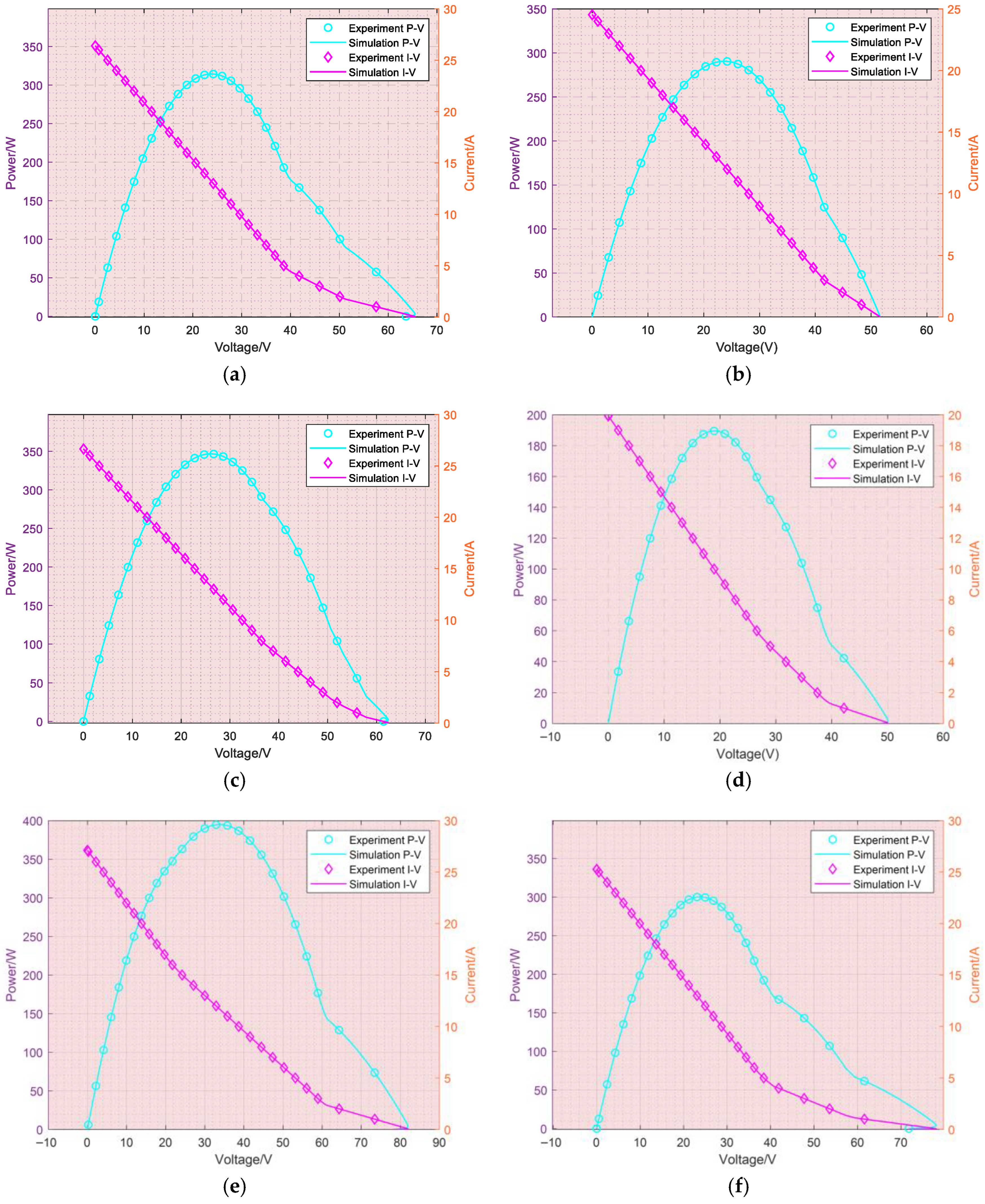
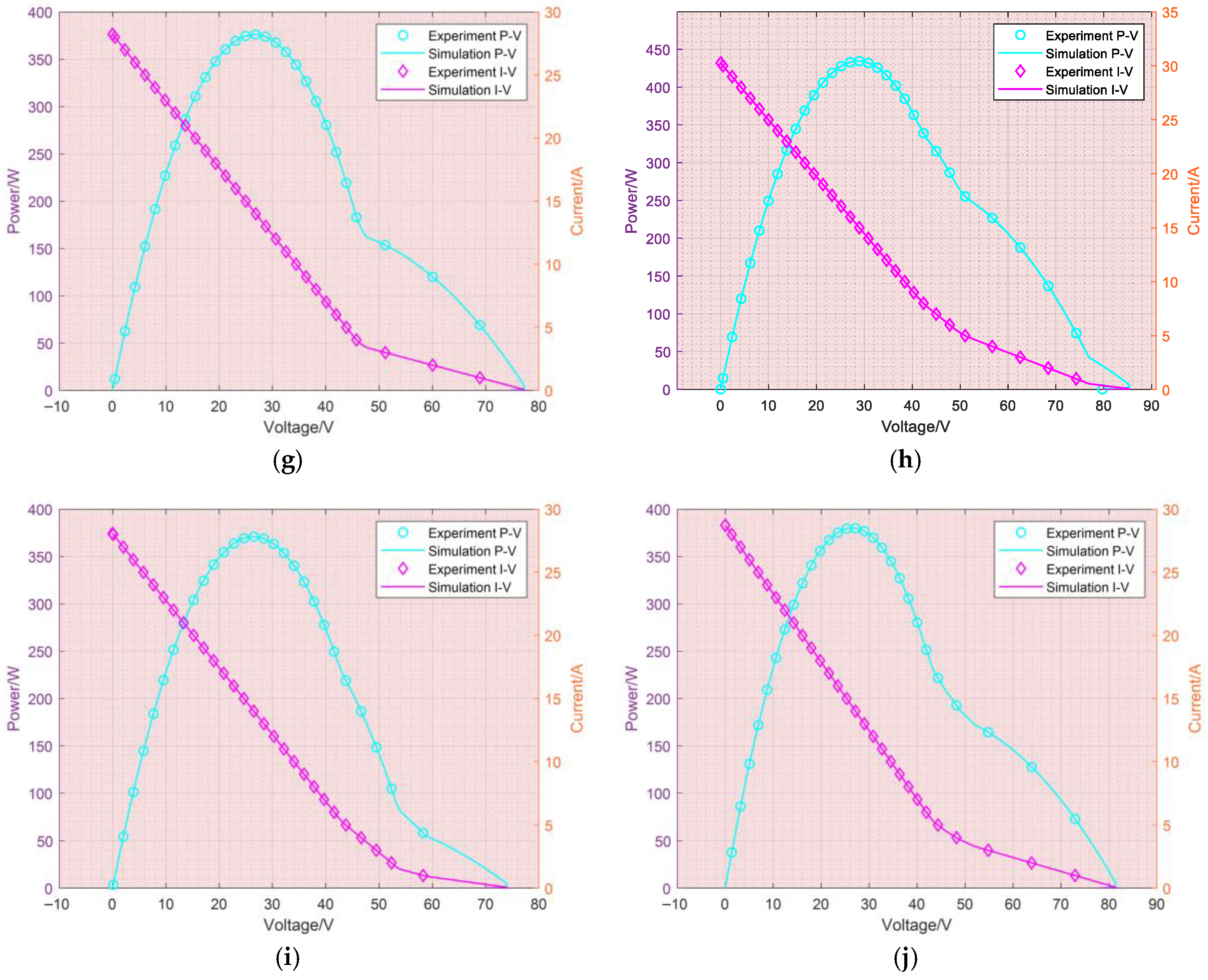
Figure 12.
Output characteristics of asymmetric (9 × 6) TEG system under ten HTD optimized by AHAC algorithm through simulation and experiment: (a) uneven row; (b) uneven column; (c) short and wide; (d) long and wide; (e) short and narrow; (f) long and narrow; (g) diagonal; (h) outer; (i) center; and (j) random.
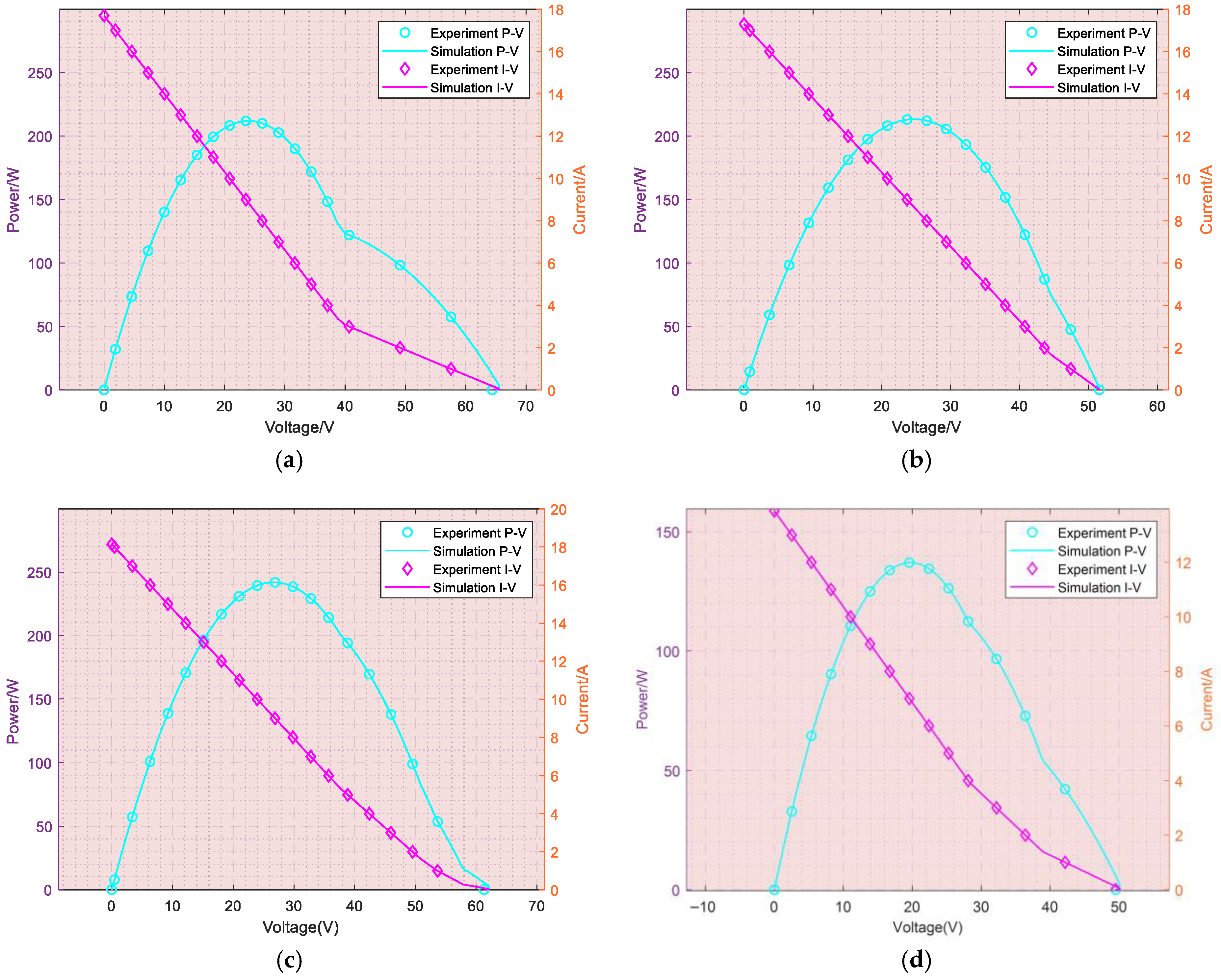
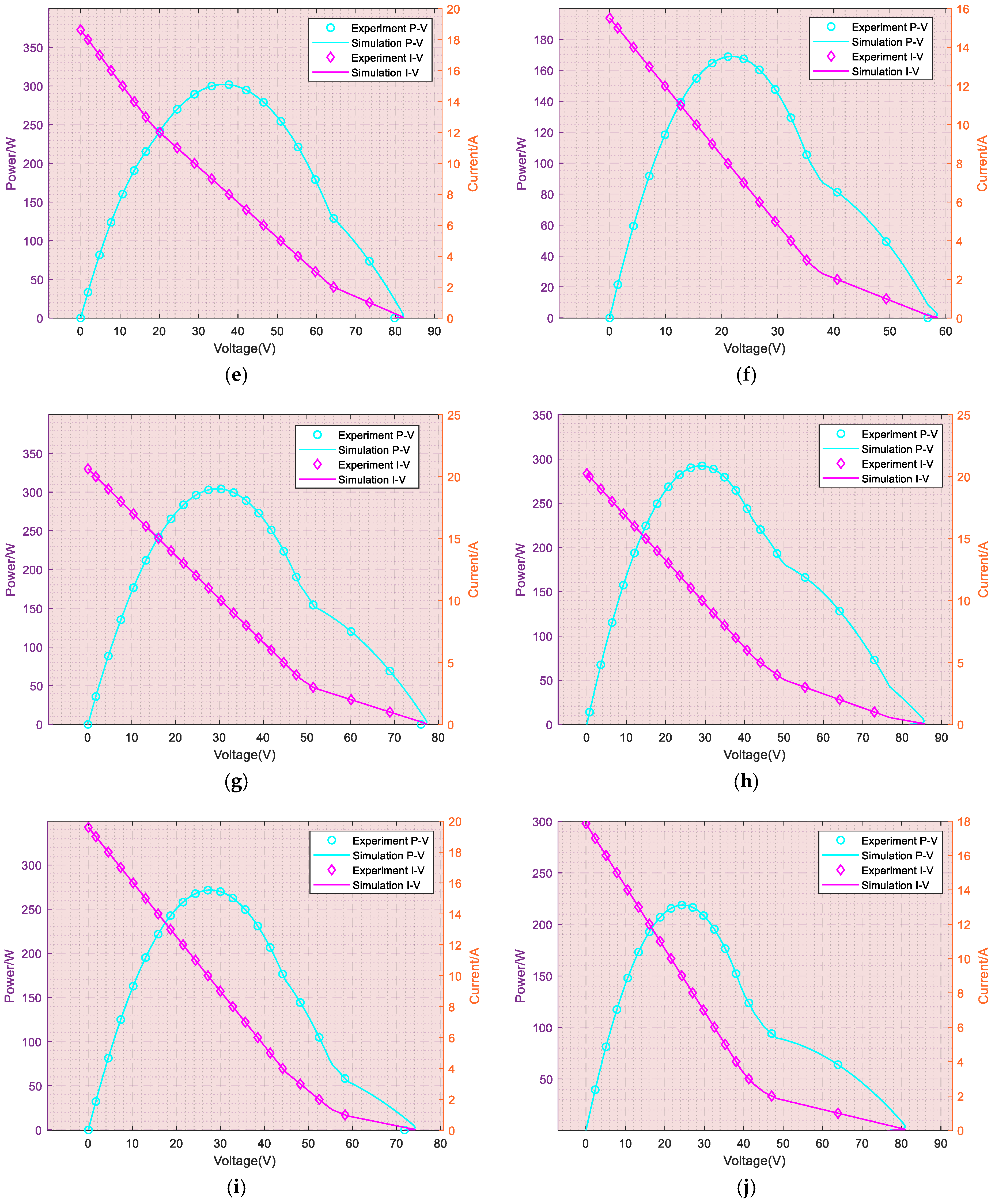
While HIL results verify the real-time execution of online control, the offline training process of AHAC involves considerable computation. Thus, the proposed method achieves real-time inference for fixed-size TEG arrays, but direct deployment on ultra-low-cost embedded platforms remains for future work.
6.2. Uncertainty Propagation and Calibration Analysis
Uncertainties in the experimental system primarily stem from two sources: (1) slight fluctuations in the HIL platform’s analog-to-digital/digital-to-analog (ADC/DAC) conversion channels, and (2) the inherent stochasticity of the learning algorithms themselves. The impact of signal conversion uncertainties on the final power output results is considered negligible. This is because the RTLAB platform offers high-precision signal I/O modules (e.g., 16-bit resolution), and the core performance metric—the enhancement rate ()—is a relative measure comparing the power after compensation to the baseline power. Since both measurements are subject to the same minor signal noise, their ratio effectively cancels out this systematic uncertainty. The algorithmic stochasticity, which affects the convergence path and time, is mitigated by the multi-run protocol described above. The reported ‘best result’ reflects the algorithm’s performance potential when it successfully navigates this stochasticity, while the convergence curves illustrate the typical learning trajectory.
Prior to the formal HIL experiments, a comprehensive calibration procedure was undertaken to ensure measurement accuracy. The voltage and current sensors within the RTLAB OPAL-RT platform were calibrated using high-precision reference instruments. A known reference voltage and current were applied to the input channels, and the scaling factors in the Simulink real-time model were adjusted until the digital readings matched the physical measurements. This process was repeated across the entire operational range of the sensors. Furthermore, the battery models and TEG array equivalent circuit parameters were meticulously validated against datasheets and characterized under standard conditions to ensure the physical accuracy of the simulated plant model within the HIL loop.
6.3. Rationality Analysis of the Proposed Framework
All the simulation and HIL results are obtained under the physically consistent AHAC framework that strictly aligns with the TEG model and optimization problem in Section 2 and Section 3.
1. The state vector integrates thermal–electrical parameters and temperature-dependent material characteristics (Equations (2) and (3)).
2. The action corresponds to a feasible battery compensation voltage, satisfying hardware constraints.
3. The reward function is fully consistent with the net power maximization objective (Equations (12)–(15)).
This design eliminates over-simplification and ensures the algorithm adapts to real TEG material properties and thermal–electrical coupling dynamics. Compared with conventional RL and heuristic methods, AHAC achieves faster convergence, higher precision, and stronger physical interpretability. Although ideal battery and quasi-static thermal assumptions are adopted for efficiency, the proposed framework can be extended to include battery SOC, transient thermal response, and temperature-dependent losses in future work.
Although the compensation battery is modeled as an ideal voltage source in this study for control-oriented analysis and algorithm verification, the influences of practical nonideal battery behaviors on the system performance are fully recognized and discussed as follows. First, the internal resistance of a real battery introduces an extra voltage drop and power loss, which slightly reduces the effective compensation voltage and lowers the actual net power gain. Second, the state-of-charge (SOC) dynamics impose inherent operational limits: the feasible range of the compensation voltage, is constrained by the remaining capacity of the battery, thereby restricting the action space of the AHAC controller. Third, round-trip efficiency losses (typically 85–95%) during charging and discharging further reduce the actual power enhancement.
Nevertheless, since the power improvement rates obtained in this work range from 3.14% to 13.91% for the 9 × 9 TEG array and 0.44% to 13.23% for the 9 × 6 array, the net performance gain remains strongly positive even under typical battery losses. Moreover, the proposed AHAC framework can be directly extended to practical battery models by including SOC, terminal voltage, and efficiency factors in the state vector and reward function. This discussion confirms that the core effectiveness and superiority of the proposed method are preserved under realistic conditions, thus supporting its practical potential.
7. Conclusions
This paper proposes a physically interpretable and methodologically coherent AHAC-based dynamic voltage compensation scheme for TEG systems under HTD. The AHAC framework adopts a problem-driven hierarchical hybrid structure with clear functional division: AC ensures stable control, Q-learning accumulates experience, PSO explores globally, and GA refines locally, avoiding both local optima and training instability. The core contribution lies in the rigorous formalization of the RL framework that strictly maps to the TEG physical model:
1. A thermal–electrical coupled TEG array model considering temperature-dependent Seebeck coefficient and internal resistance is established, and a battery-based series voltage compensation structure is designed. This structure effectively mitigates electrical mismatch caused by HTD based on Kirchhoff’s voltage law and power balance equations, avoiding complex switching circuits in traditional dynamic reconfiguration.
2. The proposed AHAC algorithm adopts a hierarchical hybrid framework, where actor–critic ensures stable real-time control, Q-learning accumulates experience, PSO performs global exploration, and GA conducts local refinement. This mechanism avoids local optima and improves convergence stability.
3. The reinforcement learning framework is rigorously mapped to the physical TEG model: the state vector consists of thermal–electrical parameters and temperature-dependent material properties; the action corresponds to actual battery voltage injection commands; and the reward function is directly derived from net power maximization, ensuring full physical consistency.
4. Verified on 9 × 9 and 9 × 6 TEG arrays under 10 HTD scenarios, the proposed method achieves power enhancement rates of 3.14–13.91% (9 × 9) and 0.44–13.23% (9 × 6), significantly outperforming Dyna-Q, PG, and GA in both optimization effect and convergence performance.
5. Hardware-in-the-loop (HIL) experiments validate the real-time feasibility and robustness of online inference and control execution, confirming the practical application potential of the proposed scheme.
This ensures complete consistency between the AHAC algorithm and the system optimization framework. Validated on 9 × 9 and 9 × 6 TEG systems under ten HTD scenarios, the proposed method achieves superior power enhancement and convergence performance. HIL experiments confirm the real-time feasibility of online inference and control execution, while offline training involves a notable computational burden.
While an ideal battery model is adopted to validate the proposed voltage compensation principle, real-world applications involve non-ideal characteristics such as internal resistance, SOC variation, and conversion efficiency. These factors reduce the calculated system efficiency , but do not affect the methodological superiority and convergence advantages of the AHAC algorithm.
Furthermore, the proposed AHAC-based dynamic voltage compensation framework exhibits strong generality and applicability to various thermoelectric (TE) materials and wider operating temperature ranges. Since the state vector of the AHAC algorithm incorporates real-time measurements of column voltage, column current, hot-side temperature, cold-side temperature, and average temperature, the controller can implicitly learn the nonlinear mapping between temperature-dependent material characteristics (Seebeck coefficient and internal resistance) and optimal compensation voltage. Regardless of the TE material type (e.g., Bi2Te3-based, PbTe-based, or SiGe-based alloys) and expanded operating temperature intervals, the proposed battery-assisted voltage compensation topology and hierarchical optimization mechanism remain valid. The control framework does not rely on fixed material parameters but adapts online to thermal–electrical coupling characteristics. Therefore, the proposed method is not limited to the TGM199-1.4-2.0 module used in this study, but can be extended to most commercial TEG modules operating under wider temperature ranges, significantly improving the engineering universality and practical value of this work.
Future work will incorporate fast thermal transient dynamics, real-time temperature prediction, battery state-of-charge, and temperature-dependent losses to improve responsiveness in highly dynamic scenarios such as automotive exhaust heat recovery, further strengthening practical applicability.
While an ideal battery model is adopted to validate the proposed voltage compensation principle, real-world applications should consider nonideal characteristics such as internal resistance, SOC variation, and conversion efficiency. These factors will slightly reduce absolute net power gains but will not affect the methodological superiority and convergence advantages of the AHAC algorithm. The proposed framework can be readily adapted to high-fidelity battery models to further improve practical applicability.
Author Contributions
Conceptualization, B.Y. and W.H.; methodology, W.H. and L.W.; validation, Y.G., Z.C., and W.H.; formal analysis, L.W. and Y.G.; investigation, Y.G. and Z.C.; resources, Z.C.; data curation, Z.C.; writing—original draft preparation, W.H.; writing—review and editing, B.Y.; visualization, L.W.; supervision, B.Y. All authors have read and agreed to the published version of the manuscript.
Funding
This work was supported in part by the Henan Science and Technology Project (No. 262102240058, 252102240091, 232102240102).
Data Availability Statement
Data is contained within the article.
Acknowledgments
The authors gratefully acknowledge the financial support provided by the Henan Science and Technology Project (No. 262102240058, 252102240091, and 232102240102), which facilitated this study. We also extend our sincere thanks to the editors and anonymous reviewers for their insightful comments and suggestions, which significantly improved the quality of this review.
Conflicts of Interest
Authors Yinyuan Guo and Zhuo Chen are employed by Xuchang KETOP Testing Research Institute Co., Ltd. The remaining authors declare that they have no known competing financial interests or personal relationships that could have influenced the work reported in this paper.
Nomenclature
| Variables | rate-of-change component of | ||
| open-circuit voltage of TEG module, V | reference values for temperature | ||
| total voltage of the nth string, V | learning rate | ||
| voltage of the block located in the mth row and nth column, V | learning rate of the action value function | ||
| supplementary voltage of the nth row of cells, V | mutation probability | ||
| desired output voltage per column, V | random small change amount | ||
| voltage required for the load, V | Abbreviations | ||
| average temperature of the hot side and cold side, °C | AC | actor–critic | |
| temperature difference between the hot side and cold side, °C | AHAC | adaptive hierarchical actor–critic | |
| temperature of the hot side, °C | Dyna-Q | dynamic programming Q-learning | |
| temperature of the cold side, °C | FA | function approximation | |
| resistance of the block located in the mth row and nth column, Ω | GMPP | global maximum power point | |
| total resistance of the nth string, Ω | GSNN | greedy search neural network | |
| total resistance of TEG module, Ω | GA | genetic algorithm | |
| total current of TEG module, A | HTD | heterogeneous temperature distribution | |
| output current for column n, A | HIL | hardware-in-the-loop | |
| power before compensation, W | HA | heuristic algorithm | |
| initial system power, W | ICSA | improved cooperative search algorithm | |
| supplementary power for each row of batteries, W | JS | jellyfish search | |
| net output power, W | MPPT | maximum power point tracking | |
| total supplemental power of the system, W | OBER | optimal battery electrical reconfiguration | |
| total output power of the system, W | PSC | partial shading condition | |
| power boost, W | PSO | particle swarm optimization | |
| number of thermoelectric units | PG | policy gradient | |
| efficiency improvement rate | P-V | power-voltage | |
| Seebeck coefficient, V/°C | PV | photovoltaic | |
| Thomson’s coefficient, V/K | QL | Q-learning | |
| action at time t | RL | reinforcement learning | |
| state at time t | SOP | solution optimization procedure | |
| Parameters | SP | series-parallel | |
| N | number of columns in TEG array | TEG | thermoelectric generation |
| M | number of rows in TEG array | TD | temporal difference |
| constant part of | V-I | voltage-current | |
Appendix A
Figure A1.
TEG unit and equivalent circuit: (a) equivalent circuit; (b) thermoelectric couple unit; (c) lithium iron phosphate battery schematic diagram.
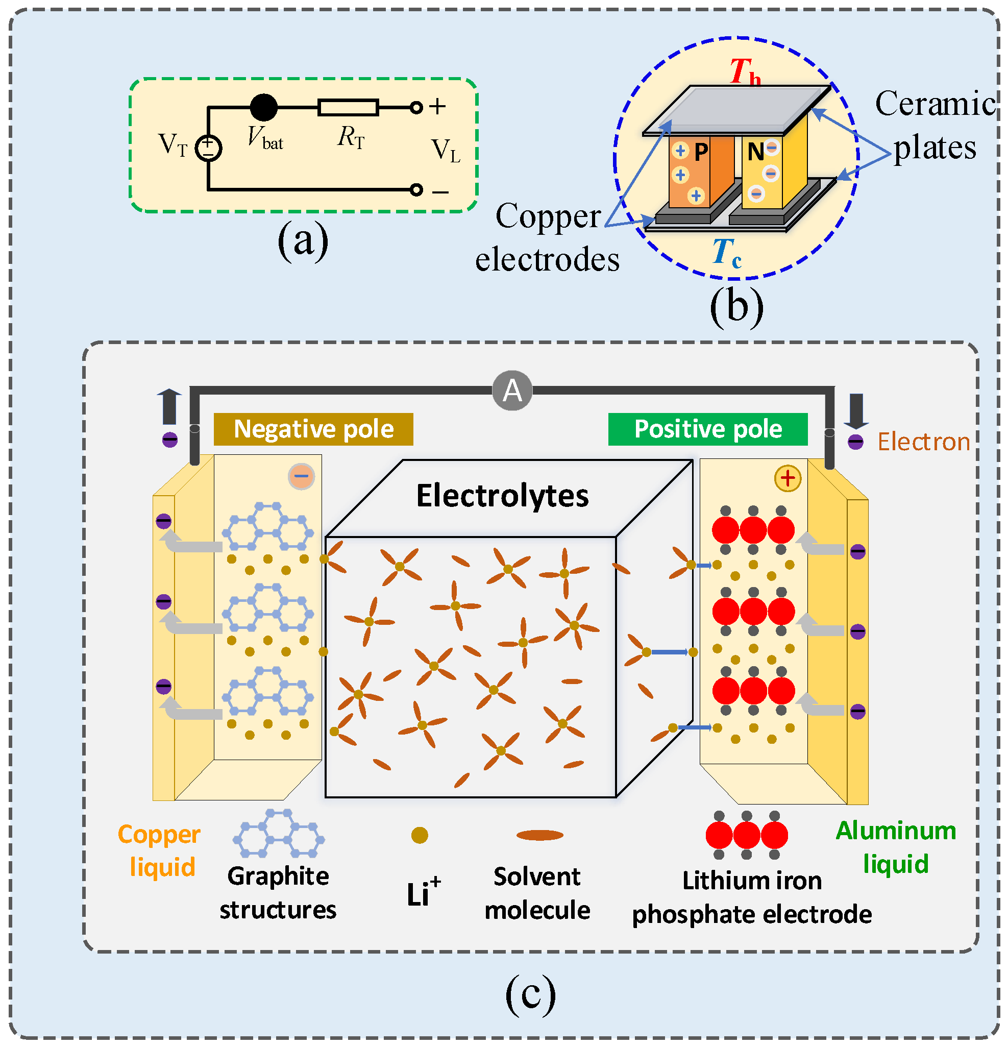
Figure A2.
Schematic diagram of AC algorithm.
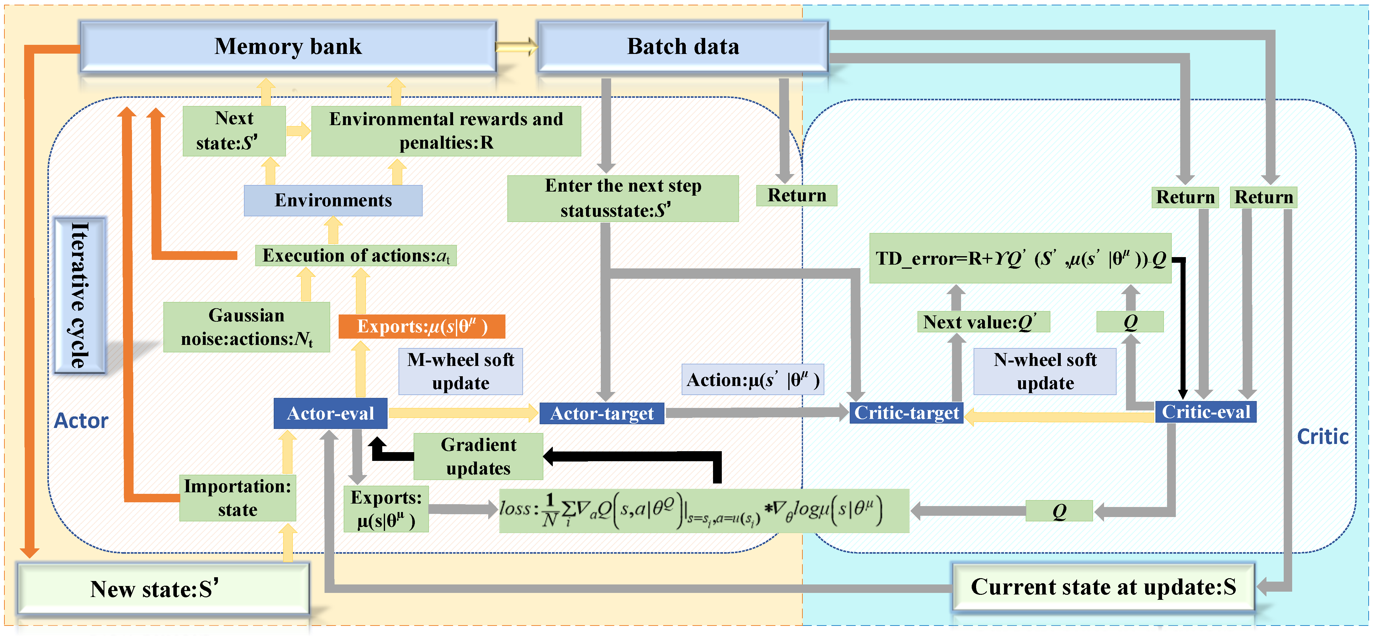
Figure A3.
Flowchart of action 1 and action 2 integration within the AHAC framework.
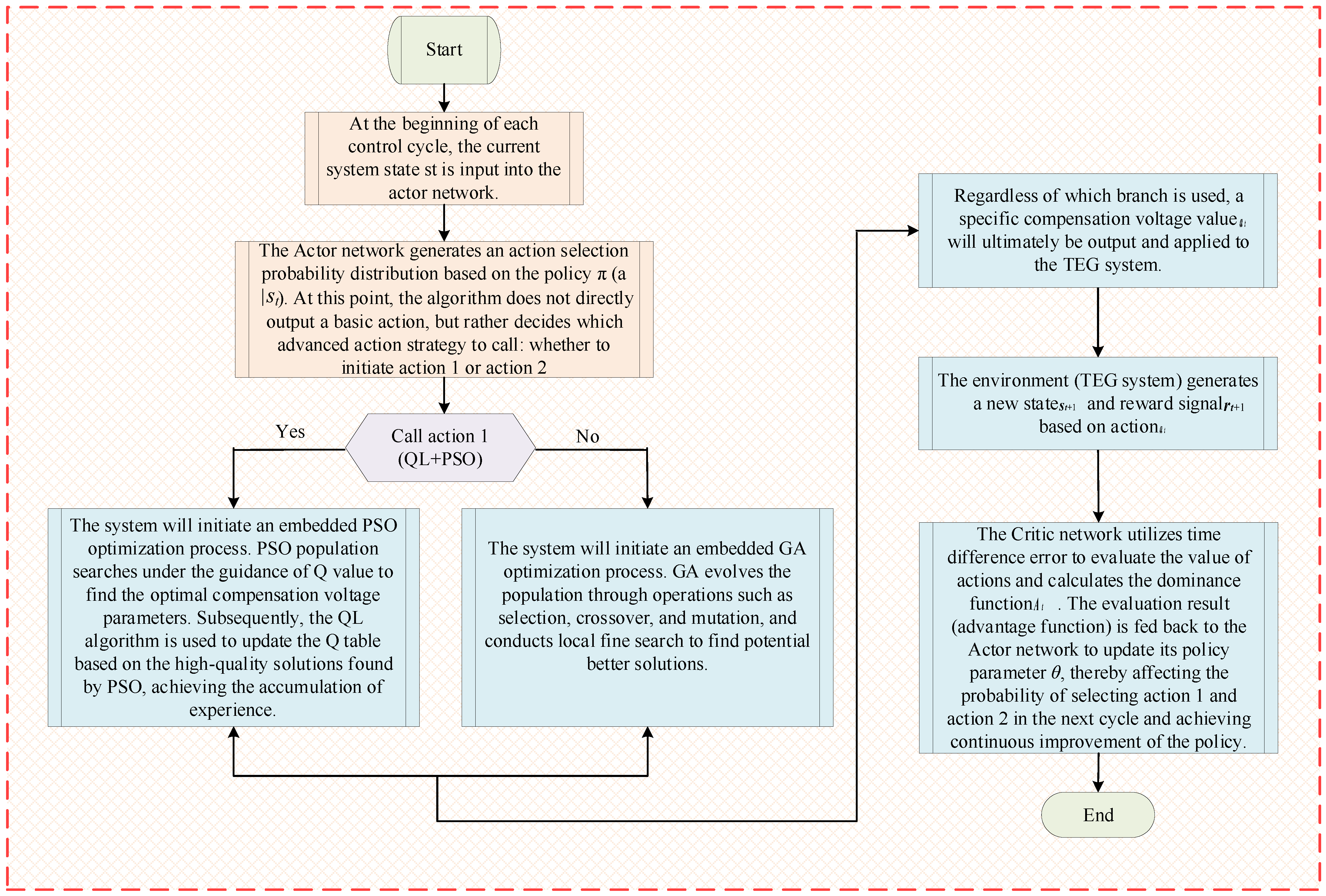
Figure A4.
Generalized diagram of AHAC algorithm.
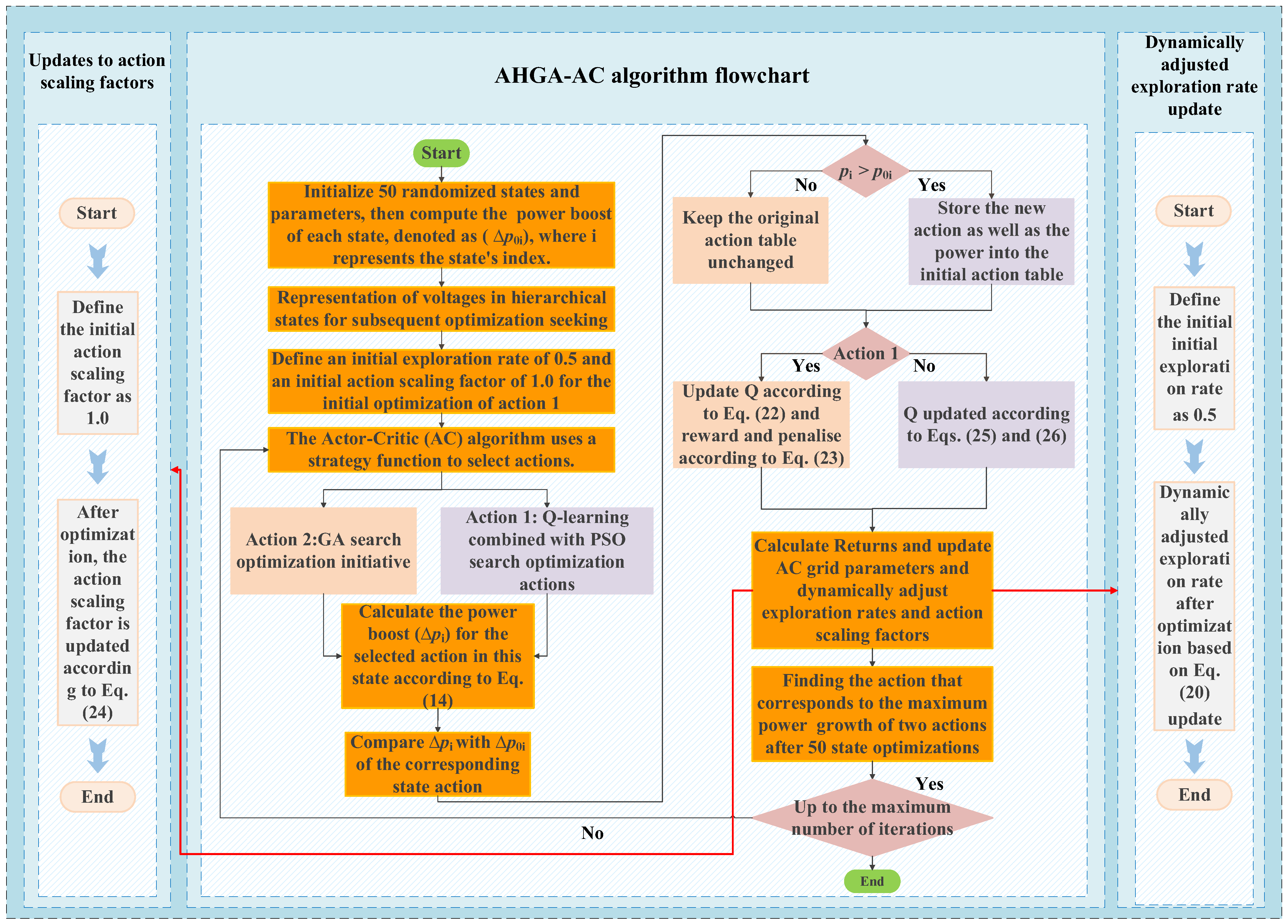
References
- Zhu, J.Z.; Miao, Y.W.; Dong, H.J.; Li, S.L.; Chen, Z.Y.; Zhang, D. Short-term residential load forecasting based on K-shape clustering and domain adversarial transfer network. J. Mod. Power Syst. Clean Energy 2024, 12, 1239–1249. [Google Scholar]
- Al-Mubarak, M.J.; Conejo, A.J. Storing freshwater versus storing electricity in power systems with high freshwater electric demand. J. Mod. Power Syst. Clean Energy 2024, 12, 323–333. [Google Scholar] [CrossRef] [Scilit]
- Saxena, A.; Shankar, R. An interactive operating demand response approach for hybrid power systems integrating renewable energy sources. Prot. Control Mod. Power Syst. 2024, 9, 174–194. [Google Scholar] [CrossRef] [Scilit]
- Yang, H.Z.; Deshmukh, R.; Suh, S. Global transcontinental power pools for low-carbon electricity. Nat. Commun. 2024, 14, 8350. [Google Scholar] [CrossRef] [Scilit]
- Pesantes, L.A.; Ruben, H.L.; Rengifo, J.; Miguel, T.; Jorge, A.; José, C.G.; Luis, F.U. Optimal design of hybrid microgrid in isolated communities of Ecuador. J. Mod. Power Syst. Clean Energy 2024, 12, 488–499. [Google Scholar] [CrossRef] [Scilit]
- Liu, D.; Yang, Q.F.; Chen, Y.; Chen, X.; Wen, J.Y. Optimal parameters and placement of hybrid energy storage systems for frequency stability improvement. Prot. Control Mod. Power Syst. 2025, 10, 40–53. [Google Scholar] [CrossRef] [Scilit]
- Rohani, H.; Sudiiarova, G.; Lyth, S.M.; Badakhsh, A. Recent Advances in Electrified Methane Pyrolysis Technologies for Turquoise Hydrogen Production. Energies 2025, 18, 2393. [Google Scholar] [CrossRef] [Scilit]
- Pera, L.; Gandiglio, M.; Marocco, P. Techno-Economic Assessment of Hydrogen-Based Power-to-Power Systems: Operational Strategies and Feasibility Within Energy Communities. Energies 2025, 18, 3254. [Google Scholar]
- Liu, W.J.; Chiu, W.Y.; Hua, W.Q. Blockchain-enabled renewable energy certificate trading: A secure and privacy-preserving approach. Energy 2024, 290, 130110. [Google Scholar]
- Yang, B.; Zeng, C.Y.; Li, D.Y.; Guo, Z.X.; Chen, Y.J.; Shu, H.C.; Cao, P.L.; Li, Z.L. Improved immune genetic algorithm based TEG system reconfiguration under non-uniform temperature distribution. Appl. Energy 2022, 325, 119691. [Google Scholar] [CrossRef] [Scilit]
- Ge, M.H.; Liu, X.L.; Jiang, J.M.; Wang, Y.B.; Zhao, Y.L.; Wang, S.X. Experimental study on thermoelectric generators with gas heat source: Thermoelectric performance, exergy analysis and economic assessment. Energy 2025, 315, 134433. [Google Scholar] [CrossRef] [Scilit]
- Yang, H.Z.; Li, M.X.; Wang, Z.H.; Ren, F.S.; Yang, Y.; Ma, B.J.; Zhu, Y.G. Performance optimization for a novel two-stage thermoelectric generator with different PCMs embedding modes. Energy 2023, 281, 128307. [Google Scholar] [CrossRef] [Scilit]
- Mehrenjani, J.R.; Shirzad, A.; Adouli, A.; Gharehghani, A. Data-driven optimization of two novel geothermal-powered systems integrating LNG regasification with thermoelectric generation for eco-friendly seawater desalination and data center cooling. Energy 2024, 313, 133846. [Google Scholar] [CrossRef] [Scilit]
- Yang, B.; Zhang, Z.J.; Zhang, J.; Cheng, X.L.; Li, J.L.; Shu, J.L.; Wang, J.N.; Wang, X.T.; Li, Y.L.; Wang, J.B. Optimal reconfiguration design and HIL validation of hybrid PV-TEG systems via improved firefly algorithm. Energy 2024, 286, 129648. [Google Scholar]
- Adithya, C.; Saravanakumar, R.; Prabhakaran, K.K. Modified Parabolic Extrapolation Based Maximum Power Point Tracking of Thermoelectric Generator for Dynamic Conditions. Chin. J. Electr. Eng. 2024, 10, 97–105. [Google Scholar] [CrossRef] [Scilit]
- Shen, Z.G.; Tian, L.L.; Liu, X. Automotive exhaust thermoelectric generators: Current status, challenges and future prospects. Energy Convers. Manag. 2019, 195, 1138–1173. [Google Scholar] [CrossRef] [Scilit]
- Zhao, Y.L.; Li, W.J.; Zhao, X.L.; Wang, Y.L.; Luo, D.; Li, Y.Z.; Ge, M.H. Energy and exergy analysis of a thermoelectric generator system for automotive exhaust waste heat recovery. Appl. Therm. Eng. 2024, 239, 122180. [Google Scholar]
- Kumar, A.; Singh, K.; Verma, S.; Das, R. Inverse prediction and optimization analysis of a solar pond powering a thermoelectric generator. Sol. Energy 2018, 169, 658–672. [Google Scholar] [CrossRef] [Scilit]
- Goswami, R.; Das, R. Experimental analysis of a novel solar pond driven thermoelectric energy. J. Energy Resour. Technol. Trans. ASME 2020, 142, 1–36. [Google Scholar]
- Goswami, R.; Das, R. Waste heat recovery from a biomass heat engine for thermoelectric power generation using two-phase thermosyphons. Renew. Energy 2020, 148, 1280–1291. [Google Scholar] [CrossRef] [Scilit]
- Kumar, A.; Singh, K.; Das, R. Response surface based experimental analysis and thermal resistance model of a thermoelectric power generation system. Appl. Therm. Eng. 2019, 159, 113935. [Google Scholar] [CrossRef] [Scilit]
- Man, E.A.; Sera, D.; Mathe, L.; Schaltz, E.; Rosendahl, L. Dynamic performance of maximum power point trackers in TEG systems under rapidly changing temperature conditions. J. Electron. Mater. 2016, 45, 1309–1315. [Google Scholar] [CrossRef] [Scilit]
- Mirza, A.F.; Haider, S.K.; Ahmed, A.; Rehman, A.U.; Shafiq, M.; Bajaj, M.; Zawbaa, H.M.; Szczepankowski, P.; Kamel, S. Generalized regression neural network and fitness dependent optimization: Application to energy harvesting of centralized TEG systems. Energy Rep. 2022, 8, 6332–6346. [Google Scholar] [CrossRef] [Scilit]
- Jing, Y.; Liang, M.; Wang, H.; Yang, Z.; Li, G.; Márquez, F.P.G.; Yang, J.; Chen, Z. Optimal economic and low-carbon scheduling in integrated energy system considering multi-level thermal energy coupling and integrated demand response. Energy Convers. Econ. 2025, 6, 83–100. [Google Scholar] [CrossRef] [Scilit]
- Yang, Y.; Pei, W.; Xu, T.; Wang, D.; Redouane, A. Federated duelling deep Q-network based collaborative energy scheduling for a power distribution network. Energy Convers. Econ. 2025, 6, 187–195. [Google Scholar] [CrossRef] [Scilit]
- Sarwar, F.A.; Hernando-Gil, I.; Vechiu, I. Review of energy management systems and optimization methods for hydrogen-based hybrid building microgrids. Energy Convers. Econ. 2024, 5, 259–279. [Google Scholar] [CrossRef] [Scilit]
- Shao, R.N.; Yang, B.; Chen, N.; Han, Y.M. Maximum power point tracking of thermoelectric generation systems under nonuniform temperature distribution: A state-of-the-art evaluation. Front. Energy Res. 2022, 10, 857261. [Google Scholar] [CrossRef] [Scilit]
- Prabhakaran, K.K.; Karthikeyan, A.; Kumar, M.; Mandal, S. A Simple Primary Key Algorithm Based Shade Dispersion Method for Maximizing PV Power Generation under Partial Shading Conditions. Chin. J. Electr. Eng. 2024, 10, 93–102. [Google Scholar] [CrossRef] [Scilit]
- Chen, Y.J.; Yang, B.; Guo, Z.X.; Wang, J.B.; Zhu, M.M.; Li, Z.L.; Li, Q.; Yu, T. Dynamic reconfiguration for TEG systems under heterogeneous temperature distribution via adaptive coordinated seeker. Prot. Control Mod. Power Syst. 2022, 7, 1–19. [Google Scholar]
- Yang, B.; Wu, S.C.; Li, Q.; Yan, Y.J.; Li, D.Y.; Luo, E.B.; Zeng, C.Y.; Chen, Y.J.; Guo, Z.X.; Shu, H.C.; et al. Jellyfish search algorithm based optimal thermoelectric generation array reconfiguration under non-uniform temperature distribution condition. Renew. Energy 2023, 204, 197–217. [Google Scholar] [CrossRef] [Scilit]
- Liu, E.; Gao, S.; Chen, X.; Li, J.; Sun, Y.; Zhang, M. Multi-source energy storage day-ahead and intra-day scheduling based on deep reinforcement learning with attention mechanism. Appl. Sci. 2025, 15, 10031. [Google Scholar]
- Aravind, P.; Winston, D.P.; Sugumar, S.; Pravin, M. Optimal battery based electrical reconfiguration technique for partial shaded PV system. Appl. Energy 2024, 361, 122942. [Google Scholar] [CrossRef] [Scilit]
- Zhang, X.S.; Yang, B.; Yu, T.; Jiang, L. Dynamic surrogate model based optimization for MPPT of centralized thermoelectric generation systems under heterogeneous temperature difference. IEEE Trans. Energy Convers. 2020, 35, 966–976. [Google Scholar] [CrossRef] [Scilit]
- Zhang, R.; Yang, B.; Chen, N. Arithmetic optimization algorithm based MPPT technique for centralized TEG systems under different temperature gradients. Energy Rep. 2022, 8, 2424–2433. [Google Scholar] [CrossRef] [Scilit]
- Wang, M.M.; Sun, L.; Guo, P.Y.; Guo, D.L.; Zhao, L.T.; Jin, Y. Overcharge and thermal runaway characteristics of lithium iron phosphate energy storage battery modules based on gas online monitoring. High Volt. Eng. 2021, 47, 279–286. [Google Scholar] [CrossRef]
- Massaguer, E.; Massaguer, A.; Pujol, T.; Gonzalez, J.R.; Montoro, L. Modelling and analysis of longitudinal thermoelectric energy harvesters considering series-parallel interconnection effect. Energy 2017, 129, 59–69. [Google Scholar] [CrossRef] [Scilit]
- Mansoor, M.; Mirza, A.F.; Duan, S.H.; Zhu, J.; Yin, B.Q.; Ling, Q. Maximum energy harvesting of centralized thermoelectric power generation systems with non-uniform temperature distribution based on novel equilibrium optimizer. Energy Convers. Manag. 2021, 246, 114694. [Google Scholar] [CrossRef] [Scilit]
- Yu, F.; Li, J.; Wang, Y. Switch current predictive control of PMSM based on exponential moving average. Energies 2024, 17, 3577. [Google Scholar]
- Twaha, S.; Zhu, J.; Yan, Y.Y.; Li, B.; Huang, K. Performance analysis of thermoelectric generator using DC-DC converter with incremental conductance based maximum power point tracking. Energy Sustain. Dev. 2017, 37, 86–98. [Google Scholar] [CrossRef] [Scilit]
- Joshi, T.; Kodamana, H.; Kandath, H.; Kaisare, N. TASAC: A twin-actor reinforcement learning framework with a stochastic update to batch control. Control Eng. Pract. 2023, 134, 105462. [Google Scholar]
- Zhang, Y.J.; Zhang, J.; Wu, G.B.; Zheng, J.H.; Liu, D.M.; An, Y.Z. Optimal power dispatch of active distribution network and P2P energy trading based on soft actor-critic algorithm incorporating distributed trading control. J. Mod. Power Syst. Clean Energy 2025, 13, 540–551. [Google Scholar]
- Khodadadian, S.; Doan, T.T.; Romberg, J.; Maguluri, S.T. Finite-sample analysis of two-time-scale natural actor-critic algorithm. IEEE Trans. Autom. Control 2023, 68, 3273–3284. [Google Scholar] [CrossRef] [Scilit]
- Han, K.L.; Yang, K.; Yin, L.F. Lightweight actor-critic generative adversarial networks for real-time smart generation control of microgrids. Appl. Energy 2022, 317, 119163. [Google Scholar] [CrossRef] [Scilit]
- Sankar, S.S.; Xia, Y.Q.; Carmai, J.; Koetniyom, S. Optimal eco-driving cycles for conventional vehicles using a genetic algorithm. Energies 2020, 13, 4362. [Google Scholar] [CrossRef] [Scilit]
- Zhao, W.M.; Zeng, T.; Liu, Z.H.; Xie, L.H.; Xi, L.; Ma, H. Automatic generation control in a distributed power grid based on multi-step reinforcement learning. Prot. Control Mod. Power Syst. 2024, 9, 39–50. [Google Scholar] [CrossRef] [Scilit]
- Jiang, C.X.; Lin, Z.; Liu, C.X.; Chen, F.X.; Shao, Z.G. MADDPG-based active distribution network dynamic reconfiguration with renewable energy. Prot. Control Mod. Power Syst. 2024, 9, 143–155. [Google Scholar] [CrossRef] [Scilit]
- Abdel-hamed, A.M.; Abdelaziz, A.Y.; El-Shahat, A. Design of a 2DOF-PID control scheme for frequency/power regulation in a two-area power system using dragonfly algorithm with integral-based weighted goal objective. Energies 2023, 16, 486. [Google Scholar] [CrossRef] [Scilit]
- Alhusseini, H.; Abdali, L.M.; Issa, H.A.; Velkin, V.I. Adaptive particle swarm optimization based model predictive control MPPT algorithm for PV systems under partial shading conditions. Results Eng. 2025, 28, 107419. [Google Scholar] [CrossRef] [Scilit]
- Wu, H.C.; Qiu, D.W.; Zhang, L.Y.; Sun, M.Y. Adaptive multi-agent reinforcement learning for flexible resource management in a virtual power plant with dynamic participating multi-energy buildings. Appl. Energy 2024, 374, 123998. [Google Scholar] [CrossRef] [Scilit]
- Wu, H.C.; Kong, Q.Q.; Huber, M.; Sun, M.Y.; Craig, M.T. Climate change will increase high-temperature risks, degradation, and costs of rooftop photovoltaics globally. Joule 2026, 10, 102218. [Google Scholar]
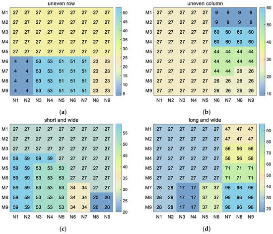
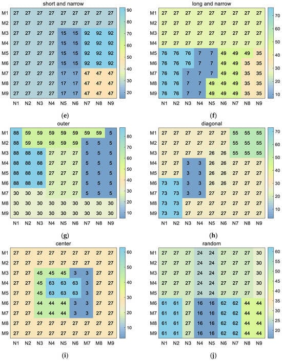
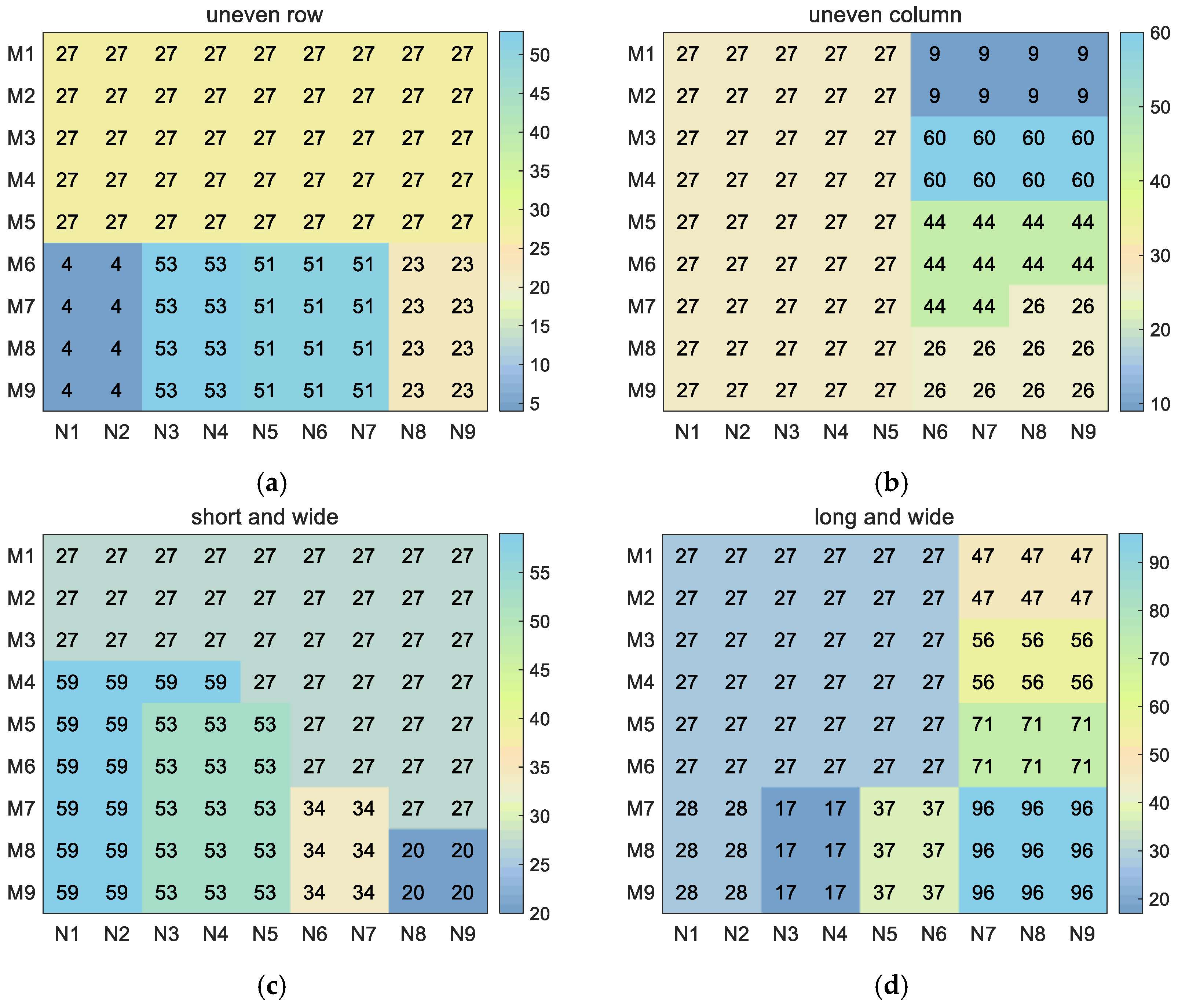
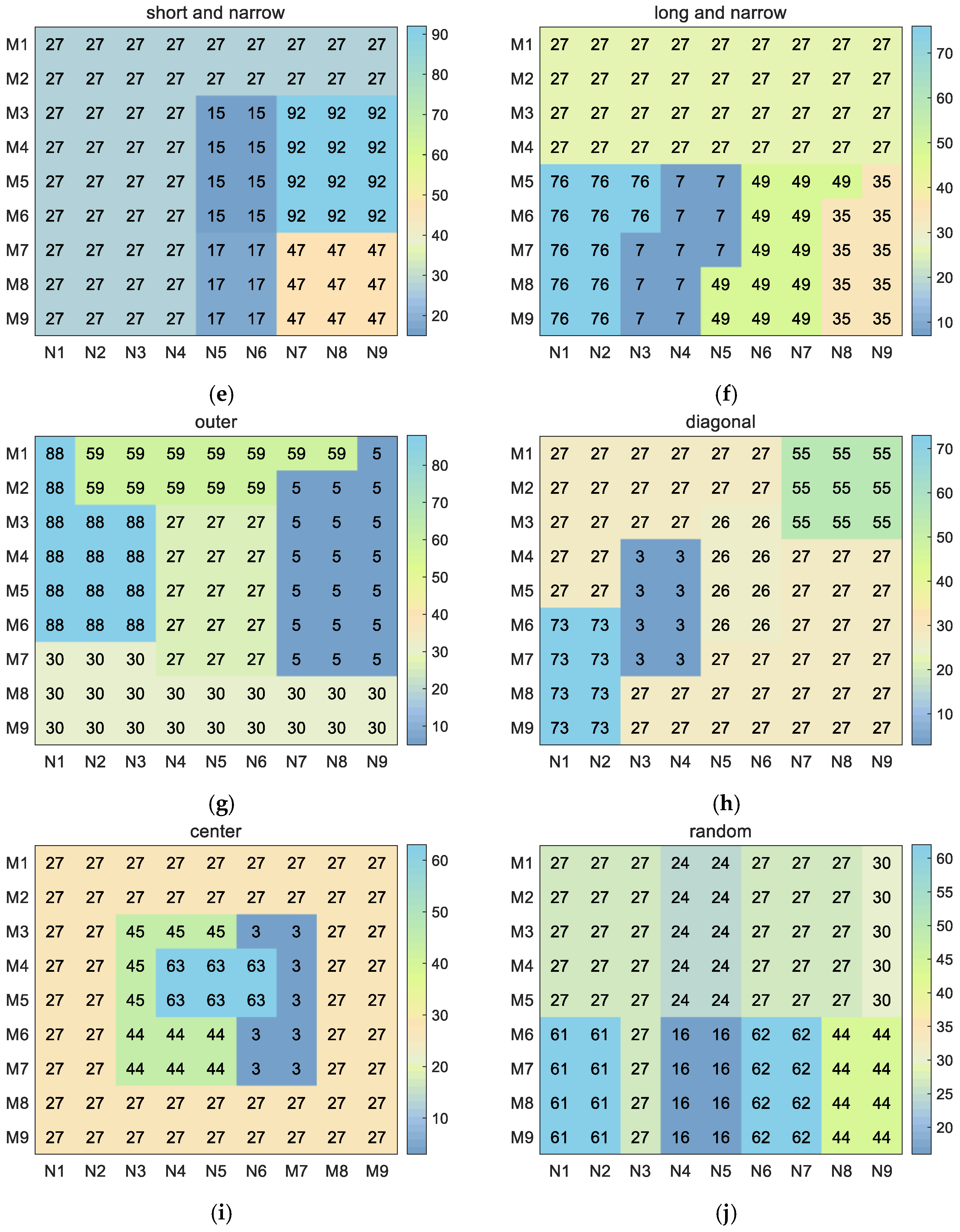
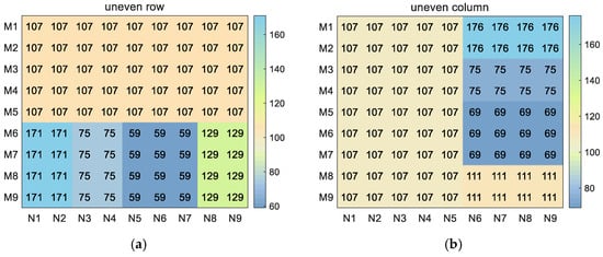
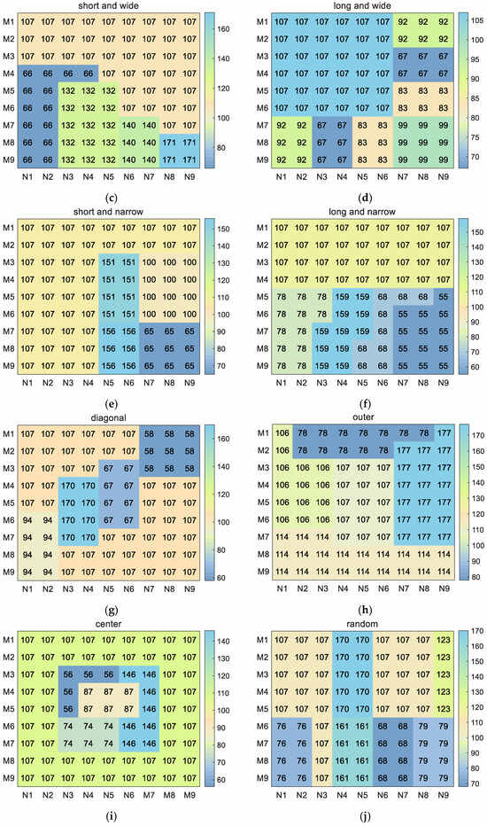
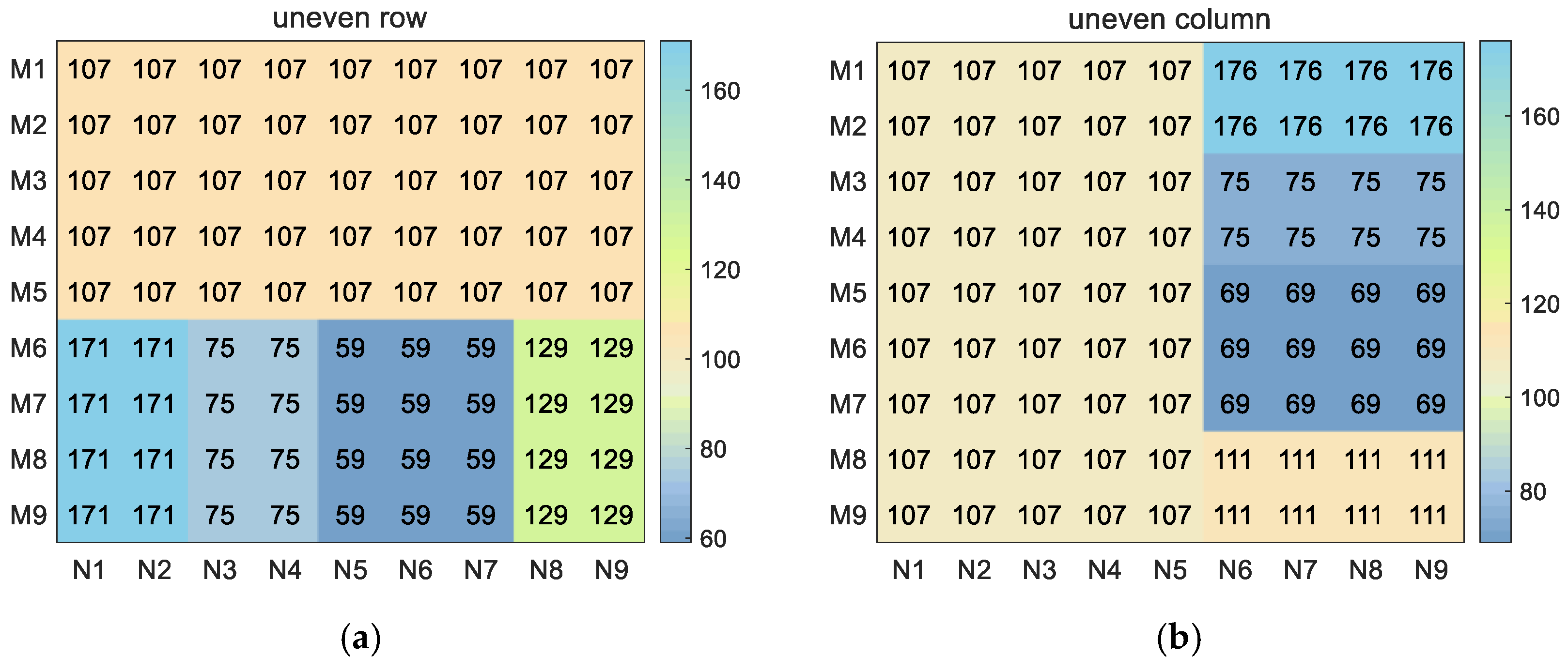
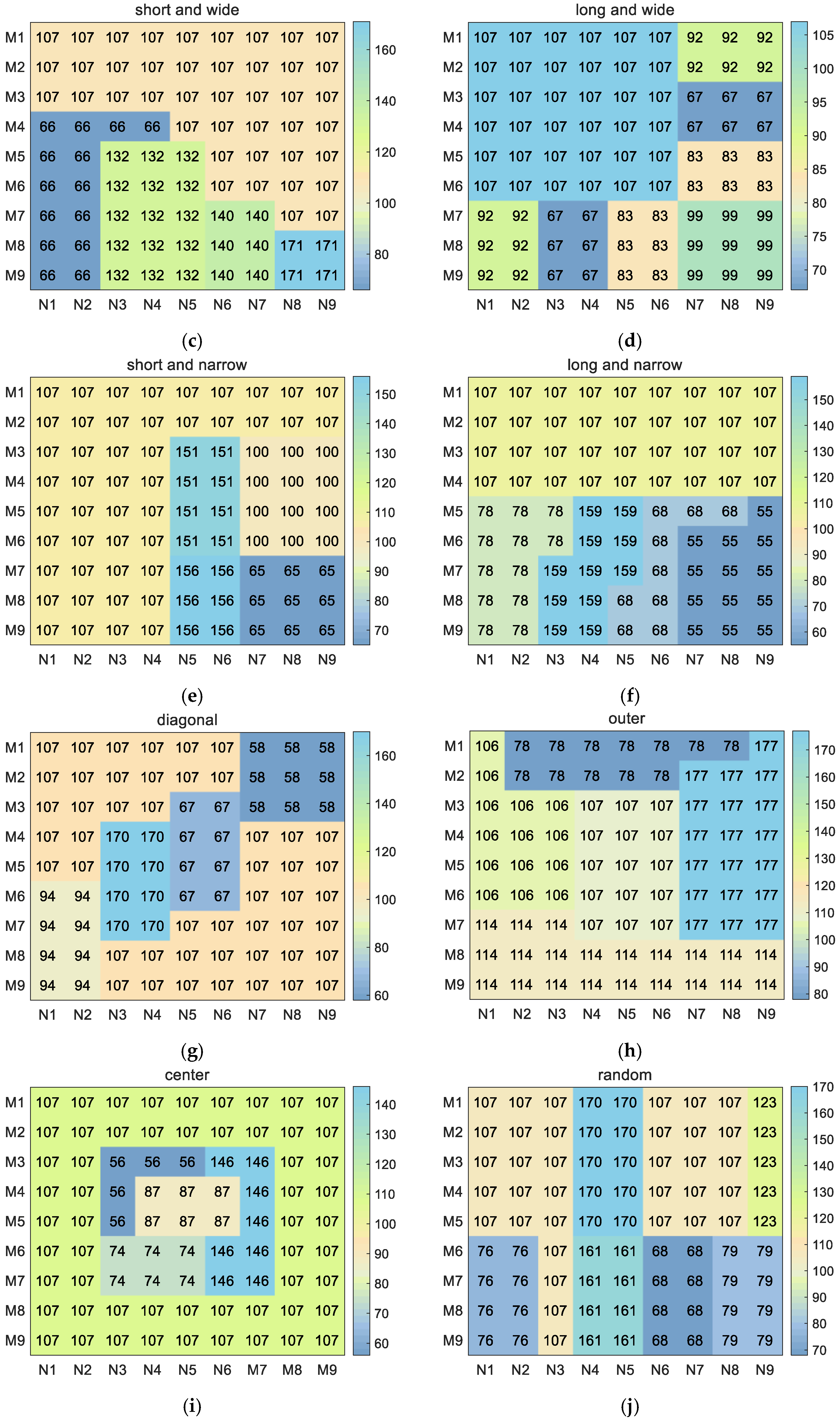
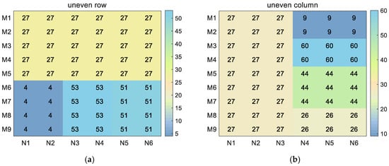
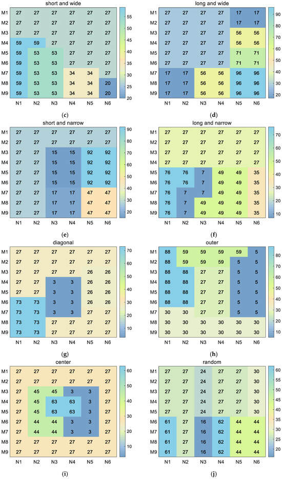
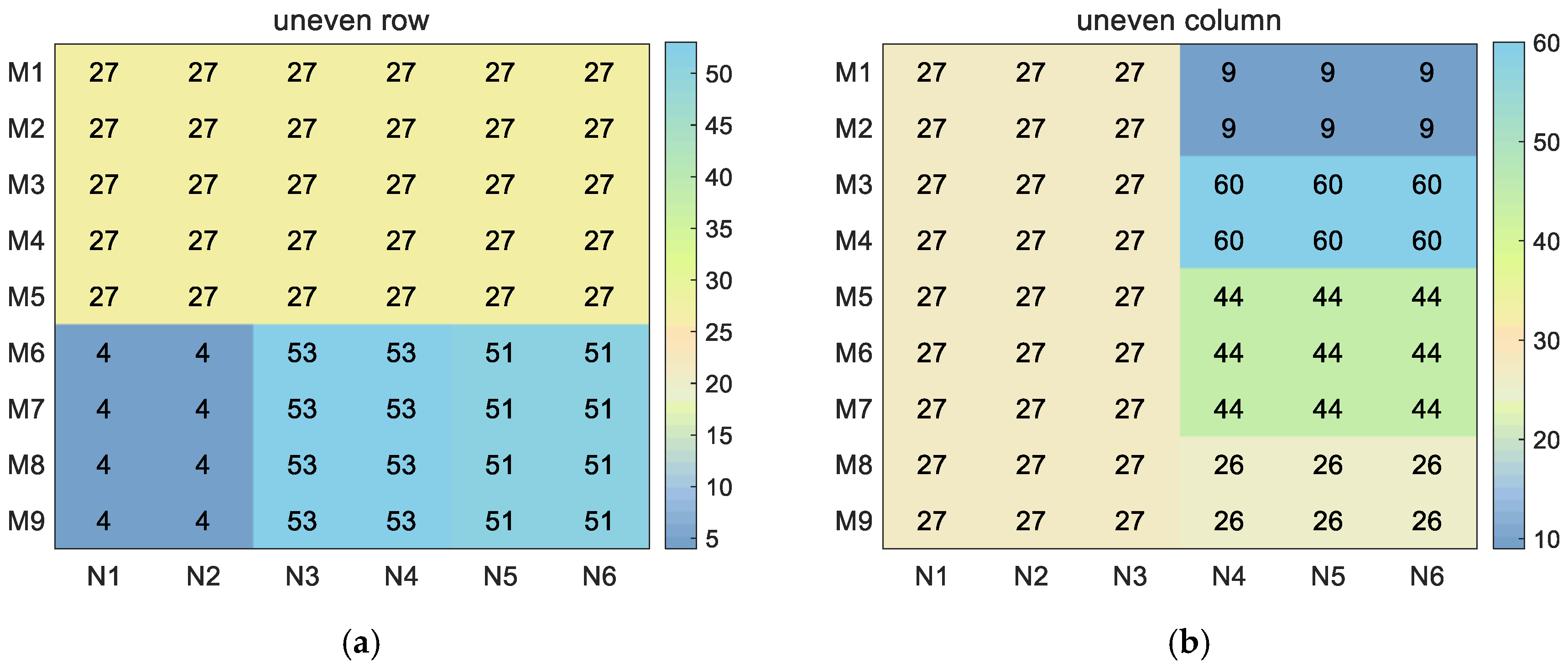
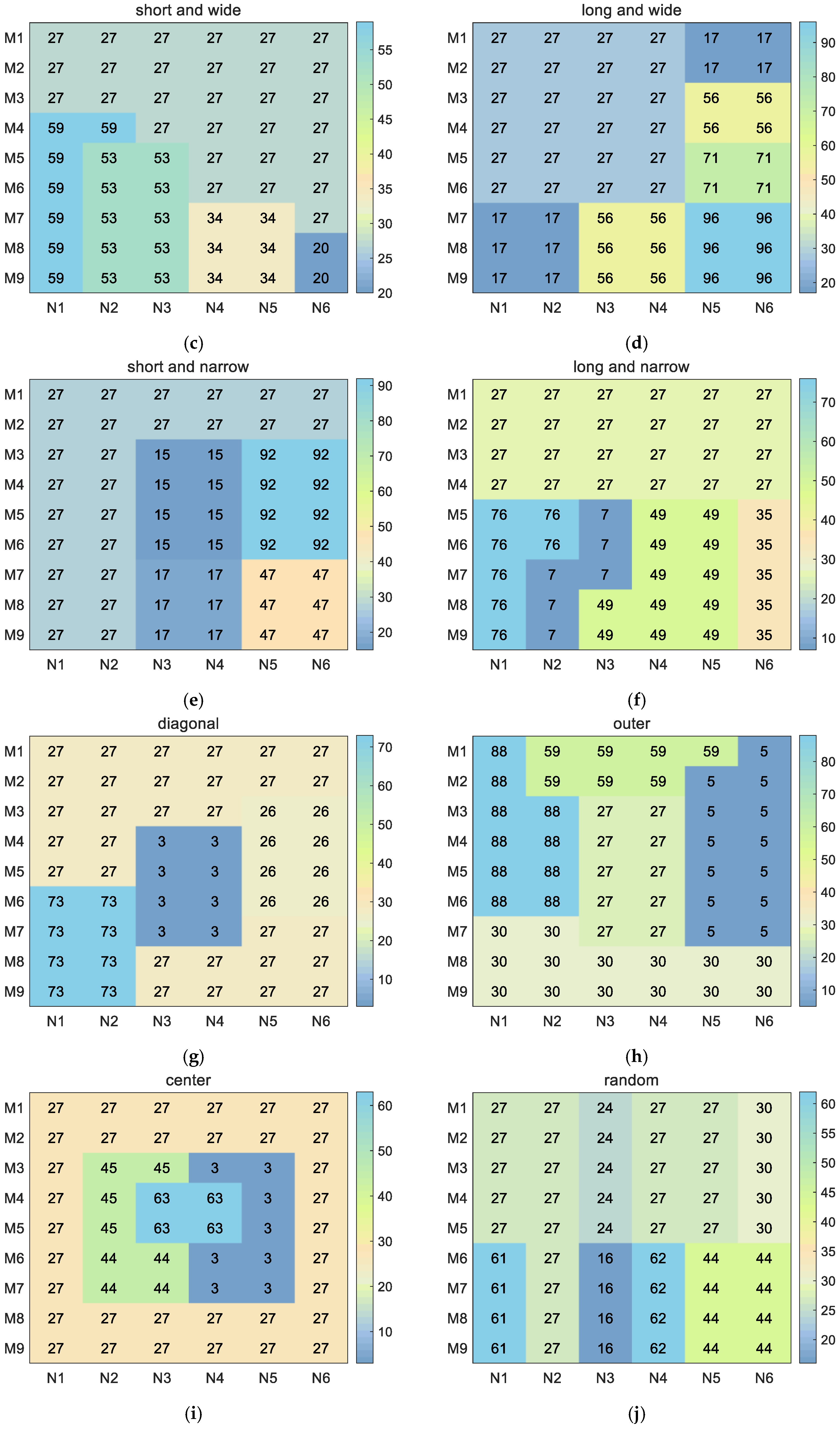
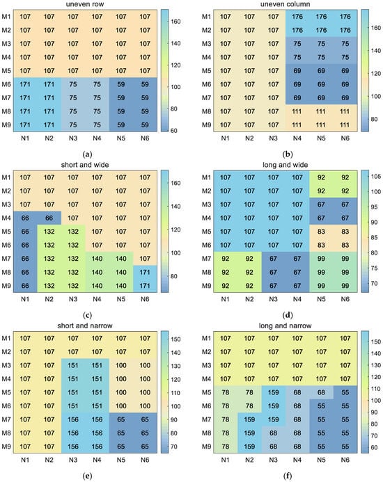
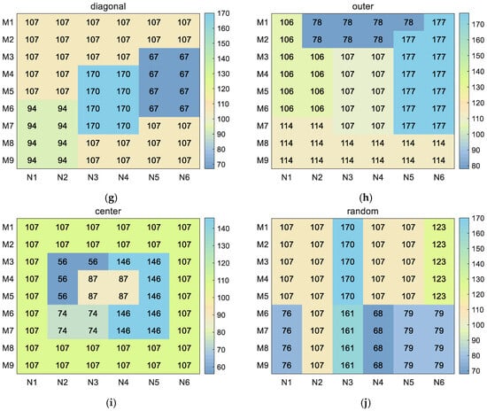
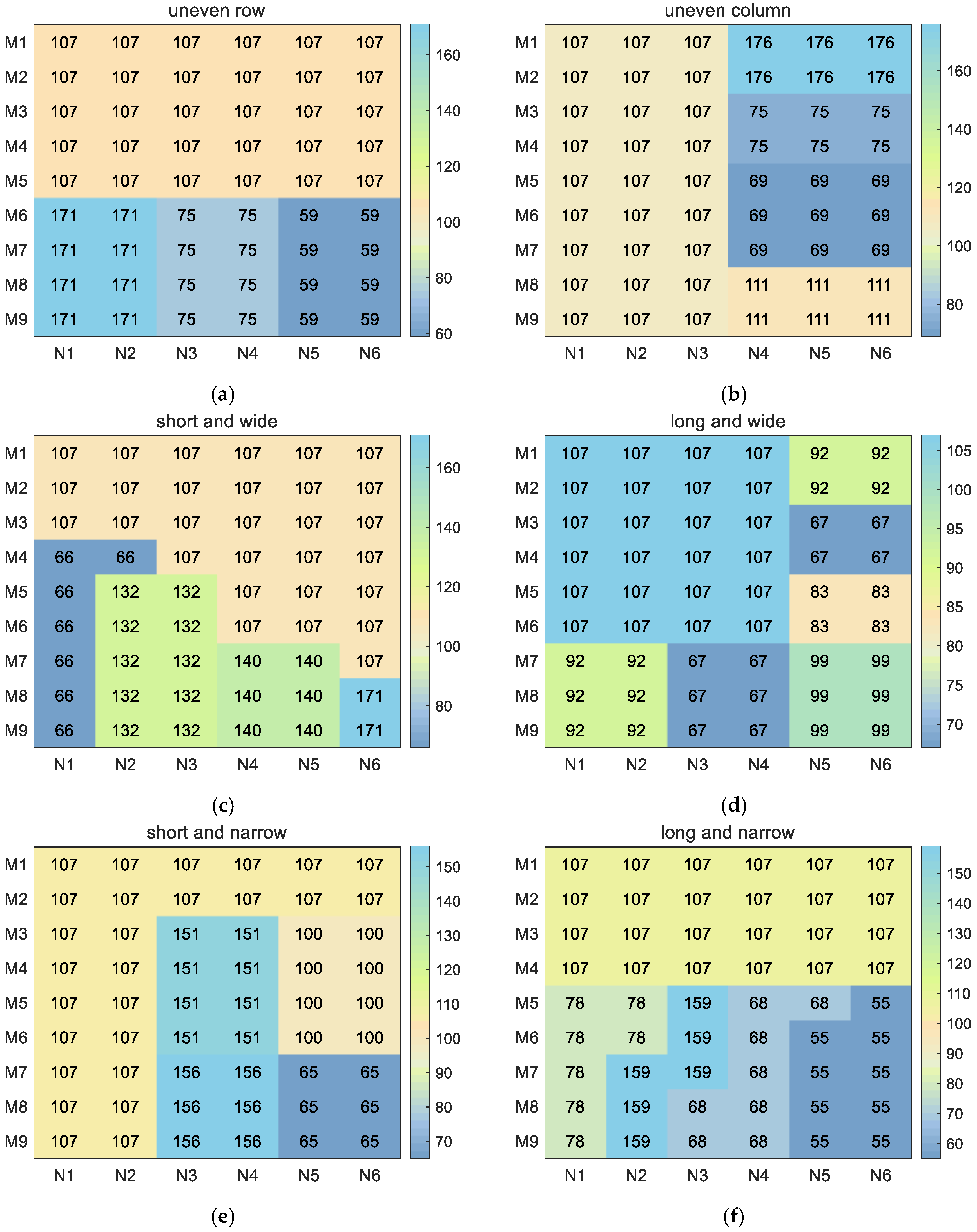
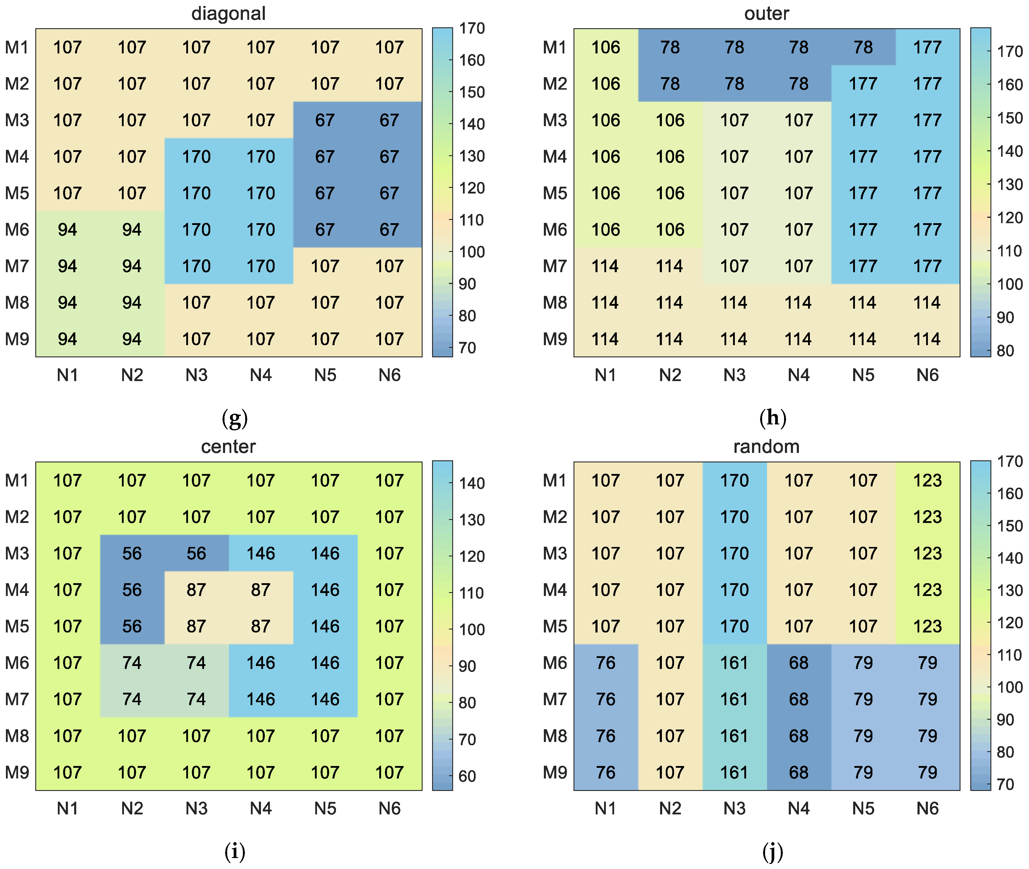

Disclaimer/Publisher’s Note: The statements, opinions and data contained in all publications are solely those of the individual author(s) and contributor(s) and not of MDPI and/or the editor(s). MDPI and/or the editor(s) disclaim responsibility for any injury to people or property resulting from any ideas, methods, instructions or products referred to in the content. |
© 2026 by the authors. Licensee MDPI, Basel, Switzerland. This article is an open access article distributed under the terms and conditions of the Creative Commons Attribution (CC BY) license.