


Abstract
This article focuses on aspects related to the physical and thermal parameters of so-called thermal-insulating paints. These materials and systems are used in two different situations: first, as agents reducing surface temperature due to solar radiation, and second, as so-called “thermal-insulating” coatings. The paper focuses on the second aspect of the applications described by the manufacturers and presents the results of the author’s laboratory tests (using an insulated heating box with two different heat sources) and field tests (in situ) on a building façade. The research methodology focuses on contact and thermal imaging measurements to assess the effectiveness and properties of reflective thermal-insulating paints, as well as analyzing their impact on the surface temperature and heat transfer coefficient of building envelopes. The conducted research showed that the use of reflective thermal-insulating paints does not significantly improve the thermal insulation of building envelopes. Measurements of the heat transfer coefficient showed a reduction of 1–7% compared to the reference wall tested. In situ measurements using temperature sensors and thermographic studies confirmed the insignificant impact of reflective thermal insulation paints on the thermal protection of external walls.
1. Introduction
The construction sector accounts for about 40% of total energy consumption. Therefore, any actions aimed at reducing its consumption can be considered a priority. This is particularly important in the context of mitigating climate change and reducing CO2 emissions. Union legislation pays particular attention to these issues and formulates a number of recommended actions for the construction sector. Examples of such regulations include EPBD [1] and Fitfor55 [2]. These requirements are implemented by individual member countries. In Poland, these regulations are included in the Construction Law [3], Technical Conditions [4] and the Act on the Energy Performance of Buildings [5]. Moreover, the Constitution [6] includes a provision in Article 5 according to which the Republic of Poland ensures environmental protection, guided by the principle of sustainable development. This implies an obligation to integrate political, economic, and social action with a natural balance for present and future generations. Additionally, construction faces challenges regarding user requirements in terms of thermal comfort.
The rational use of energy in construction is inextricably linked to issues related to various materials that reduce the energy demand in a building, including heat-protective insulation. When it comes to materials that reduce the amount of energy, scientists are conducting a number of interesting studies in this area [7,8,9,10,11,12,13,14,15,16,17,18,19,20,21,22,23,24,25].
Paper [7] describes a novel foam-concrete reinforced silica aerogel material combining the advantages of highly porous aerogel and load-bearing foam-concrete (FC-SA), which is characterized by a heat conduction coefficient of λ = 0.049 [W/(m∙K)]. In addition to creating a new material, the authors [7] also carried out numerical analyses for an example office building, taking it into account, which showed that in cold and hot regions, using FC-SA instead of traditional concrete/new materials can significantly reduce the energy consumption needed for heating/cooling rooms, as well as the consumption of cooling water. As a result of the research conducted in [7], the categories of aerogel products of insulating materials were expanded, and the technically feasible use of aerogel in buildings for thermal insulation was ensured. In the work [8], various aerogel-enriched (HGB) insulating materials were investigated, and their pore distribution and hygrothermal properties were analyzed and evaluated at different moisture contents, ambient temperatures, and humidity levels. The authors [8] showed that the thermal conductivity of the materials was generally inversely proportional to the aerogel content. For example, at 20 °C, the average thermal conductivity of the improved HGBs was about λ = 0.046 W/m K at the highest aerogel content, compared to λ = 0.058 W/m K for the reference ordinary HGB, which represents a reduction of about 24.71%. The authors [8] found a linear relationship between temperature and thermal conductivity, which indicated a slight increase in thermal conductivity with temperature, while a significant increase in thermal conductivity of materials was observed under extreme humidity conditions. In [9], the changes in thermal conductivity of rose FRCs, i.e., composites reinforced with polypropylene, basalt, carbon, and glass fibers, were measured as a function of temperature. The authors [9] showed that high conductivity of carbon and glass microfibers has a beneficial effect on the thermal conductivity of FRC, while low conductivity of PP and basalt microfibers has an inhibitory effect on the effective thermal conductivity of cement composites. Therefore, hybrid fibers can be used to modify the thermal properties of cementitious materials at different temperatures. The aim of the research included in the work [10] was to investigate the temperature dependence of thermal conductivity and the importance of surface emissivity by comparing aluminum foil and coated paper, comparing multi-layer reflective insulating panels with traditional foam insulations and determining the effect of OSB on thermal resistance. The thermal conductivity of all tested samples increases linearly in the temperature range from 5 °C to 35 °C, and the obtained results indicate that when designing the building envelope for summer and winter conditions, the high temperature dependence of multi-layer reflective insulation should be taken into account. In the work [11], three types of nanoporous insulating materials with regular geometric structures and controlled thermal conductivity were designed. It was found that the effective thermal conductivity can be reduced to λ ≈ 0.01 W/(m·K) by adjusting the method and size of the hollow-filling structures in the nanospheres in a room environment, which provides excellent thermal insulation. The work [11] represents a new strategy for the design of superinsulating materials. In the paper [24], the effect of sunlight on the physical and mechanical parameters of polystyrene with a varied addition of graphite fraction was investigated. Also, studies of mixed systems (styrofoam and mineral wool) do not show excessive deterioration of physical parameters due to environmental impacts [25].
The main active ingredient of thermo-insulating or thermoreflective paints responsible for insulating properties is microspheres. Currently, three types of microspheres are distinguished: glass, polymer, and ceramic (aluminum-silicate) [15]. Additionally, microspheres can be covered with additional nanoshells [26]. The principle of operation of microspheres increasing the thermal insulation of the partition is based on increasing the insulation by extending the heat propagation path and the significant thermal resistance of the microspheres themselves. It is assumed that the possible reduction in surface temperature is related to the influence of microspheres contained in the coating on reflectivity (R). This parameter may, under certain conditions, increase the reflection of solar radiation incident on the partition. It is assumed that this is related to the spherical, scattering shape of the microspheres and their appropriate size matched to the wavelengths of light incident on the surface under consideration [26].
HGMs are hollow, thin-walled glass beads produced with average particle sizes of approximately 11 and 18 μm. Furthermore, HGMs are sometimes called microballoons with diameters ranging from 10 to 250 μm and wall thicknesses ranging from 1 to 2 μm [27,28]. HGMs are often used as lightweight fillers in traditional materials such as cement and concrete. They give the cement lightness, low thermal conductivity, better chemical stability, and resistance to compressive stresses, which significantly outperforms others [29,30].
The experimental results of the work [13] showed that the effective thermal conductivity of cement foam (CSF) decreases approximately linearly with increasing volume content of hollow glass microspheres (HGM). In addition, 56% vol. HGM causes a more than 47% decrease in the thermal conductivity of the foam, compared to pure cementitious material. In the work [14], polysiloxane foam (SIF) reinforced with modified hollow microspheres (HM) was modified with vinyltrimethoxysilane (VMS–HM. SIF with 5% VMS–HM provided a minimum thermal conductivity of λ = 0.078 W/(m·K). In the work [15], the properties of composite materials—density, mechanical properties, and thermal conductivity—were investigated for a material in which the matrix was silicone rubber (SR) and the filler a mixture of intact and cracked HGM with different ratios. It turned out that as the share of cracked HGM increases, the density, thermal conductivity, and mechanical properties improve. The aim of the authors [16] was to produce fully inorganic geopolymer (GP)-based materials with low thermal conductivity, low density, and relatively high strength compared to similar products. They developed a type of fly ash-based foam geopolymer composites filled with inorganic hollow microspheres. According to the authors [16], the produced geopolymer foams filled with HGB are characterized by extraordinary performance and have greater potential for engineering applications than other materials.
As in the present work, in works [17,18], research methods based on a heating box were used. In the paper [17], the dynamic nature-thermal performance of building envelope elements (i.e., single- or multi-layer wall panels) was assessed using calibrated tests in a small heating chamber (hot box) with smaller-scale samples. Similar studies were carried out in the work [18], where the author developed a movable heating chamber for the preliminary assessment of the thermal conductivity of wall elements and insulating panels with dimensions of approximately 1 m × 1 m.
In the article [20], hollow TiO2 beads were considered an inorganic filler to increase light reflection and reduce thermal conductivity, thereby improving the thermal insulation properties of polyacrylic films. Hollow, spherical TiO2 as a filler is an ideal candidate for achieving increased thermal insulation, UV protection, and mechanical performance, and composite thin films have a good chance of being used in building coatings, aerospace equipment, and other fields.
To date, foamed plastics and fibrous materials based on mineral and glass fibers are the most popular in the field of heat-protective insulation. The mechanism of action of these materials is limited to improving the thermal resistance of the partitions. In a situation where the impact of radiative heat exchange on the energy balance of a building is important, these materials do not pass the test. This is where innovative solutions in the form of reflective foils and thermal insulation paints appear. A number of misunderstandings have arisen around these materials. They mainly concern the effectiveness of paints in influencing heat transfer in building structures. Manufacturers advertise them as fantastic solutions with a significant overall impact on thermal iso-latency; however, the physical basis of their operation does not indicate this. The most visible impact of these paints is in terms of protecting objects against overheating, where their properties are fully exploited. In order to determine the actual effects of thermal insulation paints, a number of practical and scientific studies are being conducted. In the paper [23], the potential effectiveness of thermal insulation paints with the addition of hollow glass microspheres at the level of 6% and sepiolite fibers at the level of 8% was demonstrated. In the article [31], a method for measuring and analyzing the thermal conductivity coefficient of paint with polymer nanospheres on a hot-box test stand was proposed. The thermal conductivity coefficient of the reflective coating was λ = 0.000794 [W/m∙K]. The authors of the work [32] subjected thermoreflective coatings to tests, allowing them to determine their physical and mechanical properties, with particular emphasis on thermal analysis of coatings at high temperatures.
In the article [33], the thermoreflective properties of composite non-organic coatings applied to various types of walls were investigated. The obtained results indicate an improvement in the thermal insulation properties of the wall and an increase in its strumienia heat reflection coefficient. In the paper [34], the obtained research results showed that the measured values of thermal resistance of the considered thermal paints and ordinary wall coverings are the same.
In the paper [35], research was devoted to the modification of microspheres in order to obtain better interfacial bond strength. The work [36] concerns the assessment of the effect of hollow glass microspheres of various sizes, derived from glass industry waste, on the durability and thermal properties of water-based paints. It was shown that balls of appropriate size (25–44 μm), completely embedded in the polymer matrix, can reduce the thermal conductivity of the coating, preventing local heat accumulation phenomena. The authors of the paper [37] considered low-emission color paints, demonstrating that, in addition to aesthetic values, the optical design provides an effective balance between energy savings and heating–cooling trade-offs, reducing the annual energy consumption needed to maintain appropriate thermal conditions in rooms. The work [38] concerns the analysis of the effectiveness of heat-reflecting paint in reducing surface and interior temperatures in a 30-year-old apartment complex. The obtained results indicate that the surface temperature of the structure covered with heat-reflecting paint was consistently lower than that of the untreated structure. In the paper [39], the authors demonstrated the possibility of improving the thermal insulation properties of acrylic paints reinforced with silica fume nanoparticles.
The author of the works [40,41,42,43] carried out a number of thermodynamic tests with nanoceramic thermal insulation coatings. He analyzed the relationship between thermal conductivity and water content. The experiments were carried out with conventional thermal insulation materials with an additional ceramic coating on one side and on both sides.
Despite many studies on the effects of microsphere paints, the results are inconclusive. This may be due to the different areas of application of this type of solution. Applications where higher temperatures predominate (recorded in industrial applications or on building roofs) indicate some potential in reducing surface temperature and thus, for example, benefits for the cooling balance. Applications with lower temperatures (e.g., for situations on vertical surfaces) indicate a small real share of such paints in the energy balance of the building. The methodological differences of the conducted research also overlap with the overall picture [44].
There are various modifications to coatings that allow for the reduction of thermal and cooling loads when used on the external surfaces of buildings. In energy-saving research, reflective coatings are seen as having significant potential to improve the thermal properties of a building as cool roofs [45] by using a roofing material with an appropriately selected reflectance. The literature shows that high reflectivity coverings can improve the energy balance of a building by up to several percent [46]. The area of application of this type of cover may also apply to technical equipment in facilities (e.g., roof air conditioners) [47,48]. Depending on the geographical location of the building, by using the cool roof technique, different effects of reducing the cooling load of the building can be achieved [21,48,49]. Also, the value of the heat transfer coefficient U of the roof coating is among the important aspects. These problems have been described, both theoretically and experimentally, in various sources in the literature and in relation to different climatic conditions [50,51,52,53]. In the temperate zone, passive solar gains can be reduced by opaque building partitions, especially during transition periods [54]. Colored heat-protective coatings also appear as a subject of research. Coatings improved by adding a pigment that affects the optical properties in the NIR region produce results in increasing the total solar reflectance value while maintaining the color tone of the paint finish [55,56,57]. Other urban areas, such as squares or roads, can also be covered with paints that reflect solar radiation, reducing the heat island effect [58,59]. Due to its high heat absorption, asphalt pavement absorbs huge amounts of solar radiation in summer, resulting in high surface temperatures. Under such conditions, a number of thermal stability problems can arise, contributing to the urban heat island effect. In the article [19], the cooling effect of various types of mineral–asphalt mixtures with a heat-reflecting coating was assessed. Studies have shown that the coating is characterized by a high light reflection coefficient due to the addition of TiO2 and hollow fillers. Good dispersion of fillers on the coating surface provides an effective cooling effect, especially in the case of hollow spheres, which are characterized by low density and thermal conductivity, which can provide better reflection and thermal insulation [19].
Also, in the case of vertical partitions (both on the inside and outside), it is possible to optimize thermal parameters by modifying the surface reflectance [60,61]. Therefore, the proper selection of materials, including the optical properties of the surface, is extremely important. Thermal insulation paints can also shape other design needs related to ensuring corrosion and fire protection requirements [33,62]. The innovation of the solutions used in the field of thermal insulation paint technology also concerns the quantitative content of active elements in the form of microspheres [63].
Article [64] presents the results of comparative studies aimed at investigating the thermodynamic properties of selected reflective coatings in the energy balance during heating periods. Dynamic external tests were used to investigate their thermal properties on the external surfaces of buildings. Two comparative coatings and a standard face coating were used for different samples. The measurement data show that a representative coating consisting of hollow ceramic microspheres has the same thermodynamic properties as a standard facing coating, while the reflective coating has a different effect on the thermal properties, depending on the thermal insulation function of the tested samples.
In turn, in the article [65], the optical and thermodynamic properties of reflective coatings applied to vertical, opaque, external surfaces of buildings in the temperate climate zone were investigated. It presents the results of comparative studies on the optical and thermodynamic properties of coatings containing hollow microspheres, in the context of their influence on the thermal properties of external walls of buildings. As a result, the measurement data do not show any differences in the thermodynamic parameters of the tested coating resulting from the reduction of thermal loads, especially in night conditions, nor in the thermal emissivity parameters compared to the standard facade coating. On the other hand, hollow microsphere coatings can contribute to improving thermodynamic parameters by up to 5% under daytime conditions for mostly sunny, poorly insulated walls, thanks to reduced cooling loads compared to standard facade coatings with identical color tones.
The main focus of energy efficiency in buildings in the temperate climate zone is on improving the thermal properties of building partitions. Significant potential exists in coatings research and development, especially in reducing thermal loads in buildings. The optical properties of building elements are often overlooked in the design of building partitions, but they have a significant impact on the heat transfer phenomenon. In general, coatings can contribute to reducing the heating and cooling loads on the building environment by lowering the surface temperatures of building partitions, contributing to lowering the air temperature [66] due to heat transfer phenomena and thus improving the external thermal comfort, and finally, they can reduce the heat island effect [65]. The prevailing analyses in the area of reflective coatings focus on horizontal roof structures, as they are most exposed to both solar radiation and heat emission into the environment [67]. Various forms of adaptation of reflective coatings [68] have been the subject of research aimed at achieving a reduction in the energy demand for cooling buildings [69]. The direct and indirect impacts of different measures on specific types of buildings were examined [70]. The degradation of optical properties of materials under the influence of climatic conditions and complex environments is an important aspect of the efficiency of surface finishing of building structures [71]. Hollow glass microsphere coatings have a wide range of applications, and their properties enable the achievement of various positive effects [72,73]. It can be stated, among other things, that coatings consisting of microspheres should reduce heat losses in winter and heat gains in summer, improve thermal comfort, and reduce the possibility of water vapor condensation. Cost-effectiveness compared to standard coatings is an aspect that must be taken into account in construction practice.
In this study, the authors attempted to determine the actual thermal parameters of thermal insulation paints and their impact on the thermal balance of a building. They used test stands based on the heat box principle for their research and carried out measurements of the paints in question on a building located in a natural environment. The direct aim of the conducted research was to determine the effect of painted reflective coatings on the thermal resistance and heat transfer coefficient of building partitions and the external temperature of the partition surface.
2. Materials and Methods
The paper considered the influence of thermoprotective facade paints. The paints were tested after being applied to real wall structures insulated with ETICS technology, and as coverings placed using painting techniques on plasterboard and sheet metal samples placed in a heating box. The tests used a Greenteg heat meter (greenTEG, Zurich, Switzerland), a Flir E95 (FLIR, Täby, Sweden) thermal imaging camera, and an SV-300 Spectrophotometer from 3Color (Skorzewo, Poland) [74].
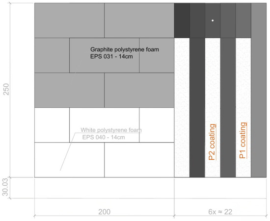
In the case of ETICS technology, the structural part of the wall consisted of solid brick with a thickness of 38 cm and a lambda thermal conductivity coefficient of 0.77 W/mK. The thermal insulation was made of polystyrene with a lambda thermal conductivity coefficient of 0.038 W/mK and a thickness of 15 cm. The EPS polystyrene layer of the ETICS insulation system was attached to the wall with an adhesive mortar of 1 cm. On the outer surface of the polystyrene, a reinforcing layer with a total thickness of 0.6 cm was applied, consisting of cement adhesive mortar with polypropylene mesh embedded in it. The outer finishing layer was silicate plaster with a grain of 0.015 cm. On the inner side, the finish was a 1.25 cm thick plasterboard fixed point-wise on gypsum mortar to the structural layer. In terms of the exposure of the tested western wall, there were no other buildings or elements in the vicinity that could have a significant impact on disturbances related to the unfavorable influence of the ambient (reflected) temperature. Longitudinal areas were marked on the existing external wall insulated with the ETICS system and painted with two paints from different manufacturers. Coatings were applied to the thin-film plaster according to the paint manufacturer’s specifications. Strips finished with ETICS thin-film silicate plaster were left between the painted strips. A small section of the wall was unplastered with an outer layer of unprotected EPS polystyrene.
In the case of sheet metal samples, the sheet made of galvanized black steel was a 0.7 mm-thick substrate. Individual samples measuring 20.5 cm × 20.5 cm were cut using a jigsaw to prevent the metal from overheating around the cutting zone, which could contribute to changing its structure. For a standard 12.5 mm-thick plasterboard, the sample size was 50 cm × 50 cm. The coatings were applied using a short-bristled nylon roller according to the manufacturers’ recommendations. The application of paint coatings was carried out in accordance with the manufacturers’ guidelines. Detailed implementing recommendations were adopted for each of the tested paints. No coatings of a specific predetermined thickness were applied. Despite this, checks on coating thickness and evenness were performed using a Blue Technology MGR-10-S-AL meter (Blue Technology, Warsaw, Poland). This device allows the measurement of coating thicknesses in the range of 0–1500 μm with an accuracy of +/− 10 μm. The thickness of each applied paint layer was measured at 6 randomly selected locations covering the entire surface of the steel plate to check the uniformity of coating application. The measured thickness is the average of these readings. Information on the recommended coating thickness can be found in the technical specifications of the relevant products. For the paints used in this study, the layer thickness values recommended by the manufacturer are the same and amount to 1 mm. It was not possible to obtain such coating thicknesses with a single application, so the paint was applied several times. The time intervals of subsequent paint applications were consistent with the time intervals included in the technical specifications of each manufacturer. After each application of the next layer, the thickness of the obtained coating was measured. The total thickness of the applied coating was, for sample P1, 1040 μm, and for sample P2, 980 μm.
For the test components constructed in this way, the temperature distribution on the tested surfaces was determined, the emissivity of surfaces covered with a selected range of heat-protective paints was examined by reference and contactless temperature measurement, and for samples based on plasterboard, the heat flux was determined using a heat meter under laboratory measurement conditions, on the basis of which the heat transfer coefficient was determined. In addition, comparative tests of the color of thermal insulation coatings were carried out using the SV-300 spectrophotometer from 3Color as supplementary tests aimed at checking the significance of the influence of paint color on the heating effect of the partition surface due to the action of the sun.
2.1. Characteristics of Test Samples
The research used a range of paints based on microspheres. Two popular and commercially available products were selected in the form of paints commonly called heat-protective. In further work, they were designated as P1 coating and P2 coating, respectively. Based on the manufacturers’ data, selected physicochemical features of the tested paints relevant to the scope of research are summarized in Table 1.
Table 1.
Comparison of the physical and chemical properties of thermal insulation paints discussed in the paper [75].
2.2. How Thermal Insulation Paints Work
The phenomenon of heat transport through a partition is described by three processes—conduction, convection, and radiation [79]. Improvement of the thermal insulation of the partition can be achieved by influencing the conduction and radiation processes. In the case of thermal insulation coatings with the addition of microspheres, improved insulation can be achieved by increasing the thermal resistance. Microspheres create additional spaces filled with air, which in turn introduces additional resistance to heat absorption and causes an extension of the heat propagation path. Due to the fact that emissivity is a feature of the boundary surface between the material and the environment, the microspheres contained in so-called thermal insulation coatings do not directly affect the emissivity coefficient of the coating in a fundamental way. However, the mechanism of action of microspheres influences the reflection and scattering of radiation by the near-surface layer, which may translate into a change (usually a decrease) in the temperature of the sunny surface relative to the surface without layers of covering with microsphere elements.
Infrared (IR) Radiation Reflection Mechanism
The phenomenon of thermal energy exchange through radiation uses electromagnetic waves with a wavelength of 0.8 ÷ 400 μm, which are called infrared waves. This process occurs between the surfaces of solids and liquids. This type of heat exchange does not require physical contact between thermal energy exchange objects. Physically, radial heat transfer is described by the Stefan–Boltzmann equation [80].
This equation is true for a black body. In the context of rooms surrounded by walls, thermal radiation can be considered heat exchange between bodies with gray body properties. The surfaces of building partitions are different from perfectly black bodies. Then the density of the heat flux transferred by radiation between two gray surfaces is, according to [81],
where
ε1–2—average emissivity coefficient of heat exchange surfaces by radiation,
σ = 5. 677 × 10 −8 [W/m2·K4]—the radiation constant for a black body, and
T1 i T2—surface temperature of bodies in Kelvin.
2.3. Research into the Thermal Properties of ‘Thermo-Insulating’ Paints
The paper presents research on the properties of so-called thermal insulation paints at three different test stands. Selected paint samples were tested using a heating box with a radiative heat source, where the emissivity coefficients of the tested materials were verified based on contact and contactless methods. The tests were then carried out in a heating box with a convective heat source, where the heat transfer coefficient was determined based on the measurement of heat flux density and temperature difference. The third site consisted of research samples on the actual wall of a building located in Upper Silesia, where the effect of paint coatings on the obtained temperatures of the external surfaces of the partition was verified.
2.3.1. Heating Box with Radiant Heat Source
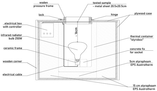
In order to determine the emissivity coefficient of the tested thermal insulation coatings, an insulated test box was constructed, whose task was to direct the heat flux in one direction (towards the tested elements). The heat source was an industrial infrared light radiator with a power of 250 and dimensions: diameter 125 mm × length max. 170 mm.
The radiator used emits energy in the range of 700–800 nm, which qualifies it as a shortwave radiator. According to the device’s rating card, radiation parameters remain stable throughout the nominal operating period of 5000 h. The radiator reaches full thermal stability within seconds after being turned on. The power consumption (250 W) and color temperature (2800 K) are constant during operation, with a stable supply voltage (230 V) ensured. Taking into account the test time being significantly shorter than the nominal operating time of the radiator, it is reasonable to assume that with the passage of time, there will be no slow evaporation of tungsten from the filament and its deposition on the inner wall of the bulb. Therefore, there will be no slight decrease in radiation efficiency during the measurements, or such an effect will be negligible.
An infrared heater with a nominal radiation angle of 60 degrees, an R125 bubble shape with a double reflector, and a transparent finish was moved away from the surface of the heated sample by a distance of 16 cm. This arrangement allowed for uniform concentration of radiation in the given research areas. The diagram of the heating box and the description of its basic elements are illustrated in Figure 1.
Figure 1.
Heating box with radiant heat source (Poland, Gliwice) [75].
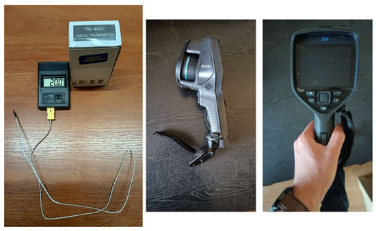
The tested samples were subjected to thermal radiation emitted by a bulb placed in the box—an infrared heater. The bulb power was matched to the thermal strength of the housing using an electronic regulator. The temperature of the heated surface of the tested samples was measured at time intervals of 30 s. The test cycle for a single sample, covering one side of the sample, lasted 10 min. Temperature measurements were performed in parallel in two ways. The first was a measurement using a TM902C-type temperature meter (Shenzhen, China) with a probe, a K-01-type thermocouple (Figure 2). The device allows the recording of temperatures from −50 to 1300 °C, with a resolution of 0.1 °C from 0 to 500 °C.
Figure 2.
On the (left), the TM902C meter with a probe; on the (right), the Flir E95 camera [75].
The second way to measure the surface temperature of the tested samples was thermal imaging tests. For their implementation, a thermal imaging camera from the E95 series by FLIR was used (Figure 2). This camera allows recording temperatures ranging from −20 to 1500 °C with a thermal sensitivity of 30 mK. The resolution of the bolometric sensor is 464 × 348 pixels, and the refresh rate is 30 Hz. The measurement was performed from a fixed location at a distance of approximately 1 m from the surface of the sample being tested. The temperature inside the laboratory during the measurements was constant at 20 °C. There was no interfering radiation in the room. In order to determine the emissivity of the tested sample surfaces, a marking tape with a known emissivity coefficient of ε = 0.96 [-] was used, which in itself does not constitute a clear thermal resistance. In the FLIR Thermal Studio thermogram processing program, the actual temperature averaged over the area marked with the marking tape was read. Then, at a location symmetrical to the glued tape, the average temperature of the area constituting a rectangle with the same area as the piece of tape was read. By varying the emissivity coefficient, this temperature was adjusted to the actual value established for the reference tape. The emissivity coefficient determined in this way represents the actual value for the tested surface.
2.3.2. Heating Box with Convection Heat Source
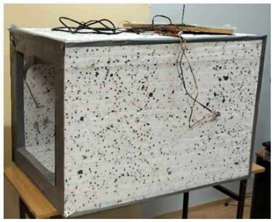
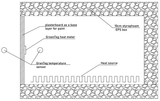
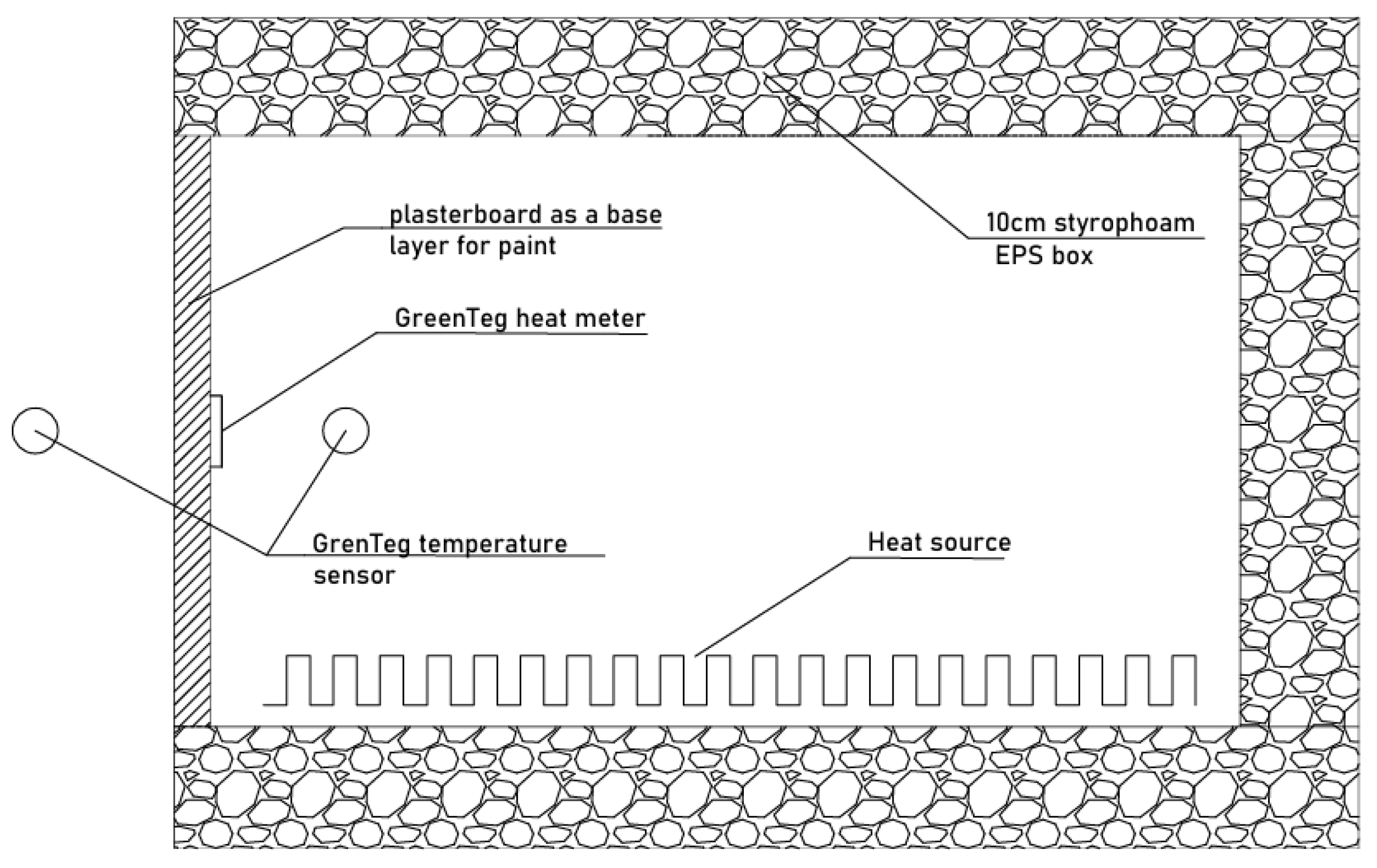
The tests were carried out based on selected guidelines of ISO 9869-1 standard [82], generating the required thermal conditions using a polystyrene heating box with the structure shown in Figure 3 and Figure 4. Heating mats were found in the inner part of the measuring track to force a temperature difference. A reference sample in the form of a plasterboard was mounted in the mounting hole. The samples were then painted with the two types of thermoprotective paints tested. Samples were placed with the paint-coated side to the heat source and outside. Measurements were performed using a Greenteg g-SKIN U-Value Kit (greenTEG, Zurich, Switzerland). Sensitivity of the heat meter was 11.14 μV/(W/m2). Relative error ±3%. The heat meter was placed on the unpainted side of the sample. Temperature sensors on the inside and outside were placed in the air. The heat transfer conditions were non-stationary. The unsteady nature of heat transfer is taken into account in determining the value of the heat transfer coefficient by adopting the calculation procedure proposed in the cited standard [82].
Figure 3.
Heating box with convection heat source (Poland, Gliwice).
Figure 4.
Diagram of a heating box with a convection heat source, built-in sample, and heat meter.
For the above-described test stand, the measurement model is described by the following equation:
where
Input standard uncertainties can be described as follows:
- -
- for heat flux, determination error 3%. If we treat it as a normal distribution, we assume the measurement uncertainty as
- -
- for temperature, the measurement accuracy is ±0.1 °C, which usually means a rectangular distribution. Therefore, the measurement uncertainty is
- -
- for the temperature difference, the measurement uncertainty is
The sensitivity coefficients are equal to
Therefore, the complex standard uncertainty is equal to
Dividing it by , we obtain
The final standard relative uncertainty is equal to
Assuming a confidence level ≈ 95%, we assume k = 2, which gives an expanded uncertainty of
Hence, the relative value is
2.3.3. In Situ Field Tests on a Prototype Wall
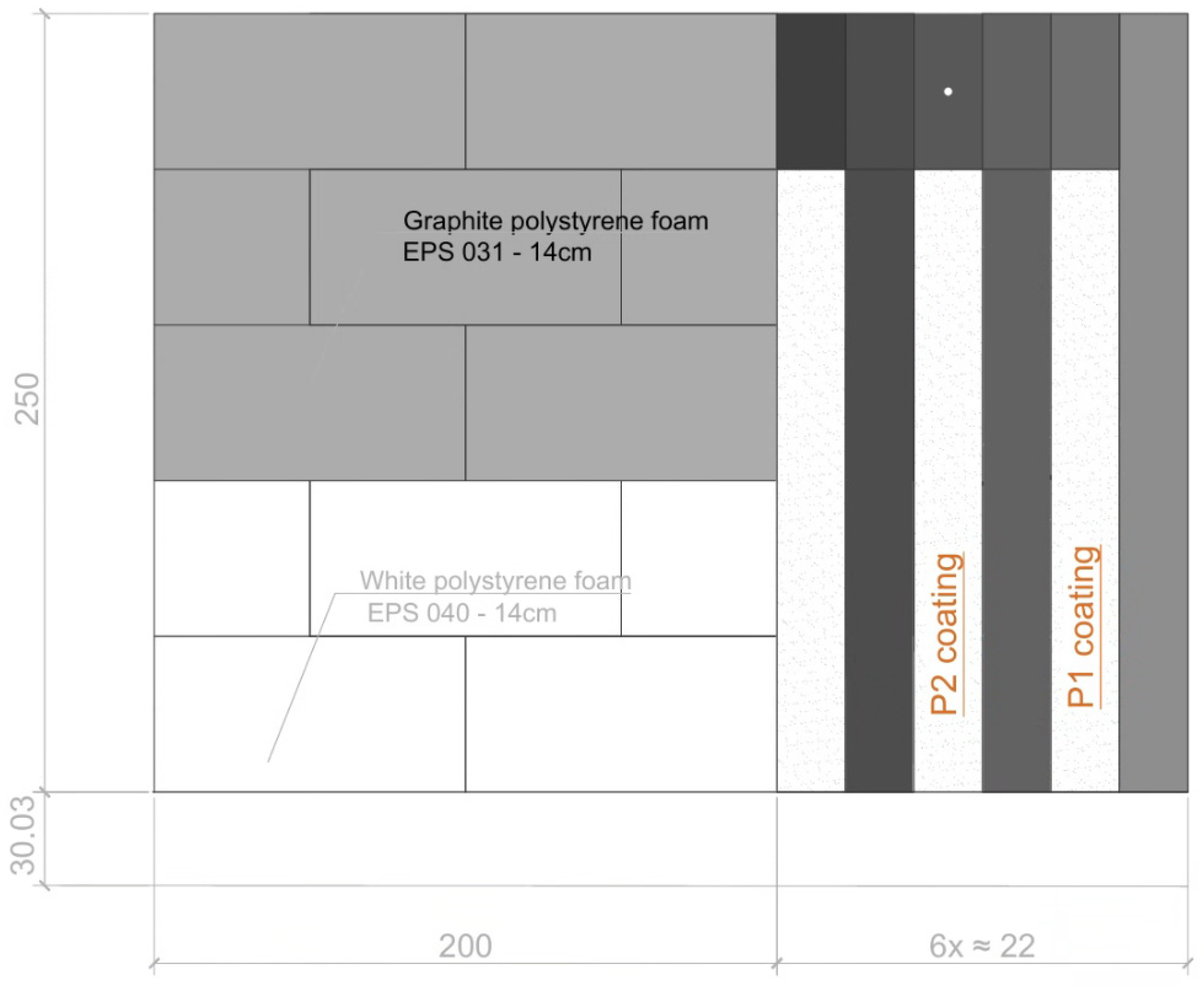
In situ studies aimed to determine the effect of thermoprotective paints on the temperature of the facade of a building located in Upper Silesia (Poland). The tests were carried out in real conditions on an external multi-layer partition insulated using ETICS technology. The structural part of the wall consisted of solid brick with a thickness of 38 cm. The insulation was made from an assortment of polystyrene with a thickness of 15 cm. The research scheme is shown in Figure 5. Measurements were performed using a multi-channel data recorder type AR207. Temperature sensors of the PT100 type were used, guaranteeing a measurement resolution of 0.1 °C. Temperature recording was performed at a time step of 10 min. Measurements were carried out over a period of one month. In addition, the partition was inspected using a thermal imaging camera. Thermal imaging measurements were performed with a FLIR E95 thermal imaging camera (FLIR, Täby, Sweden) with the parameters described for laboratory tests. The operating parameters of the microbolometric uncooled detector enabled precise temperature measurement on the outer surface of the wall. Due to the need to cover a relatively large area at a short distance, a 42° wide-angle lens with an automatic calibration function relative to the camera was used together with image refinement technology. This allowed for an increased level of detail in the thermograms obtained. To minimize the negative impact of changing external environmental conditions, which is a particular problem for obtaining reliable test results, thermographic measurements were performed in the absence of precipitation and for wind speed v < 1 m/s. For the external wall in question, its surroundings included the sky, the ground, and the adjacent buildings. These elements were characterized by varying temperatures. In order to determine the ambient temperature, a method was adopted to measure the radiation temperature of the surface of crumpled aluminum foil, unwound and attached to the plane of the wall in question. The emissivity of the tested surface of the ETICS insulation system was determined by comparison with a tape with known radiation characteristics. The distance of the thermal imaging camera from the surface of the tested wall was determined using the laser rangefinder built into the thermal imaging device. Thermal imaging measurements were performed from a distance of approximately 3 m from the tested surface. The emissivity for the P1 coating was 0.92, and for the P2 coating, 0.91. FLIR Thermal Studio software v.2.0.77.0 was used to process the thermograms. Thermal imaging studies were carried out in two stages: The first measurement was made on a sunny winter day (air temperature te = −3 °C, relative air humidity 81%, solar radiation intensity per vertical surface of 220 W/m2). The second measurement with a thermal imaging camera was made at night (air temperature te = −7.5 °C, relative air humidity 84%, no solar radiation).
Figure 5.
Scheme of the location of selected research samples on an external partition located in the natural environment [75].
2.3.4. Additional Comparative Tests of the Color of Thermal Insulation Coatings
Comparative color tests of thermal insulation coatings were performed using an SV-300 spectrophotometer from 3Color. One of the most important systems for describing numerical colors is the CIELAB color space [83]. CIELAB space is based on the concept that color is a sensation resulting from the interaction of light, an object, and an observer. The observer receives the light reflected from the object, which is described using the CIELAB space parameters. The difference between two colors in CIELAB space is the distance between the positions of those colors. This is expressed by the parameter ΔE*ab, for which the formula is as follows:
where
ΔL*—difference in brightness coordinate,
Δa*—difference in green/red color coordinate,
Δb*—blue/yellow color coordinate difference.
The measurement was performed spectrally with d/8 geometry (SCI), a D65 illuminant, and an observer set at an angle of 10°. The color space adopted was L*a*b*. The test on the facility was preceded by a white calibration and a black calibration procedure. Color measurements were carried out on the surface of two plates with thermal insulation coatings P1 and P2. Six partial measurements were performed on each plate.
As a result of the measurements, the difference in the brightness coordinate ΔL* = −0.22, the difference in the green/red color coordinate Δa* = −0.07, and the difference in the blue/yellow color coordinate Δb* = −0.58 were obtained. The obtained result of the difference between two colors in CIELAB spaces was ΔE*ab = 0.62. This value constitutes a small difference, the so-called close tolerance, not always noticeable by a non-expert [83] but mostly by a skilled expert. This translates into a negligible effect on surface heating related to the color difference between samples P1 and P2.
3. Results and Discussion
This section summarizes the results of tests on the emissivity coefficient, the heat transfer coefficient values, and the obtained temperature waveforms for the facade under real conditions.
3.1. Results of Emissivity Coefficient Measurements Using a Heating Box with a Radiant Heat Source
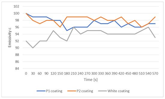
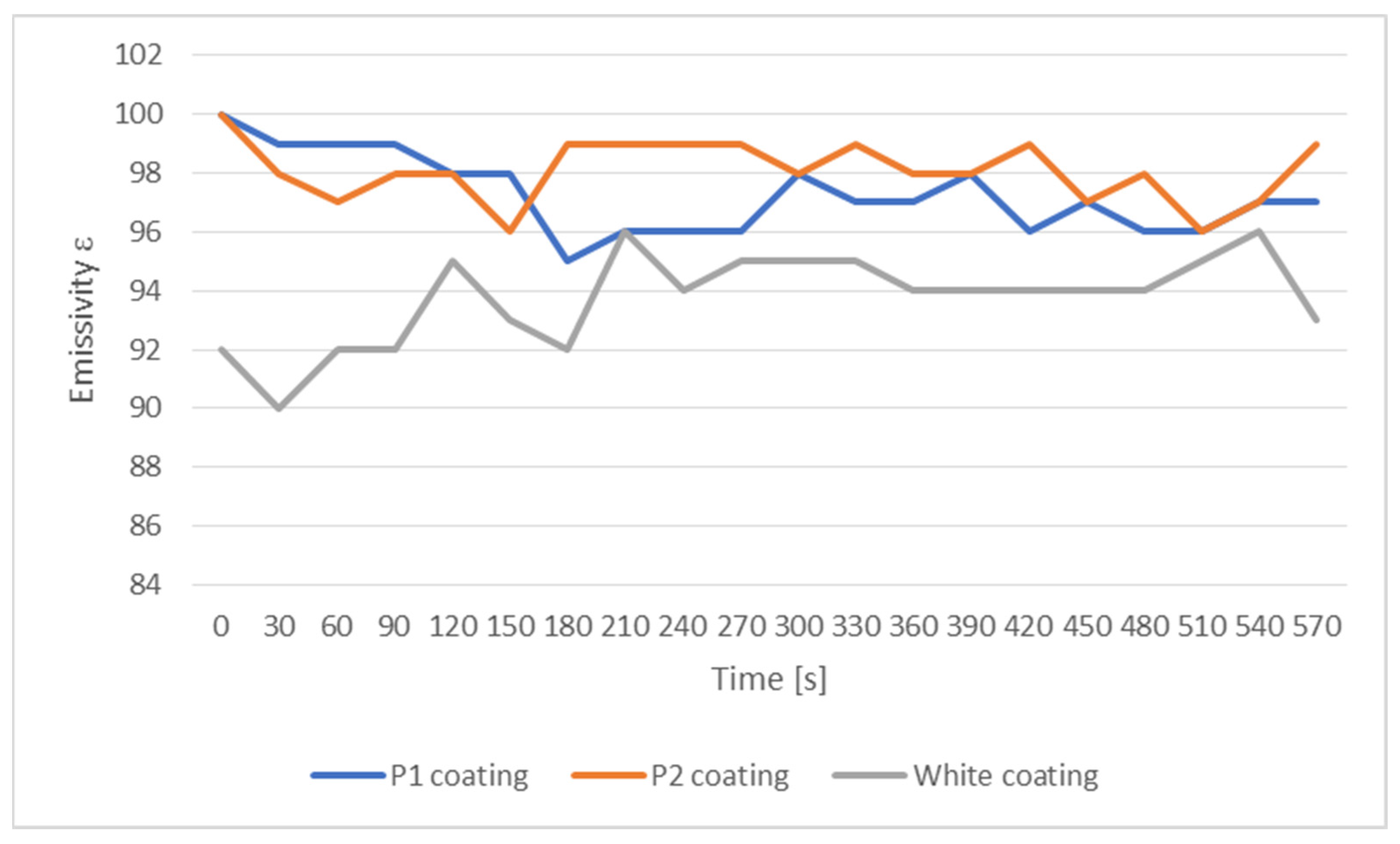
Table 2 summarizes the obtained temperature values on the surface of the tested samples covered with paints with the addition of microspheres and white paint without the addition of microspheres as a reference point. Based on the methodology presented in Section 2.3.1., the actual emissivity coefficients were determined. The average emissivity coefficient was determined based on temperatures rising over a specific time period. Figure 6 illustrates the results obtained during the study. Based on the measurements carried out, it can be seen that the value of the emissivity coefficient is independent of the temperature range considered in the study (corresponding to the temperatures encountered on real facades).
Table 2.
Summary of temperature measurements of the tested surface with determination of emissivity coefficients based on the standard for samples painted on the outside [75].
Figure 6.
Measured, average emissivity coefficient of heat-protective coatings and white typical paint, also without paint.
3.2. Measurement Results for a Heating Box with a Convection Heat Source
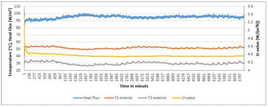
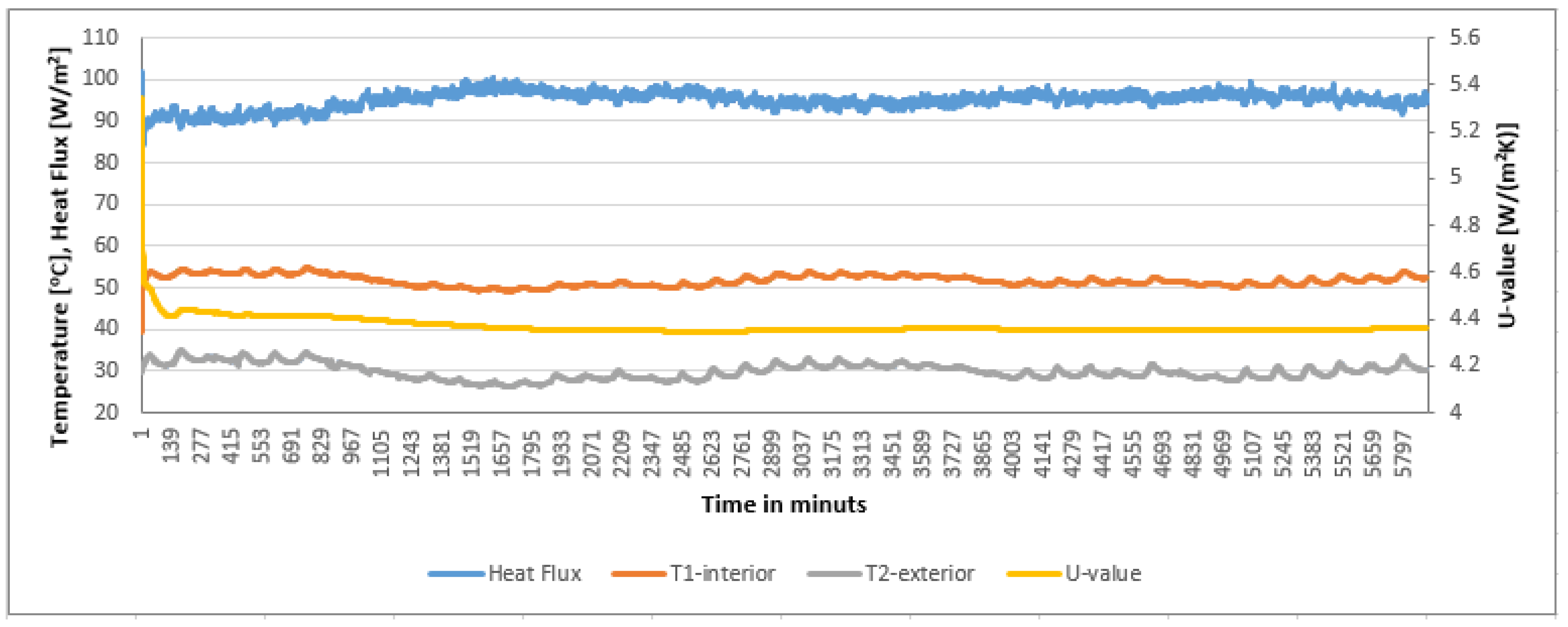
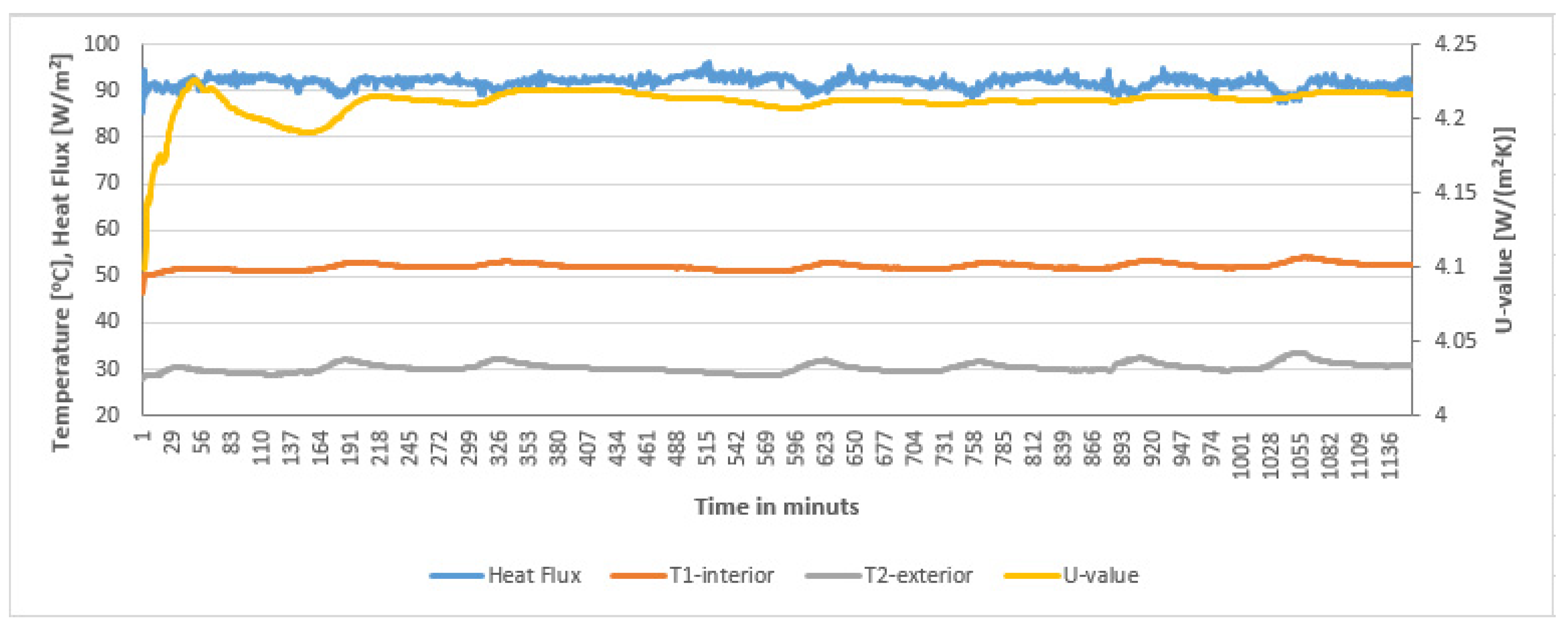
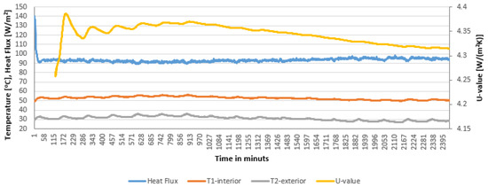
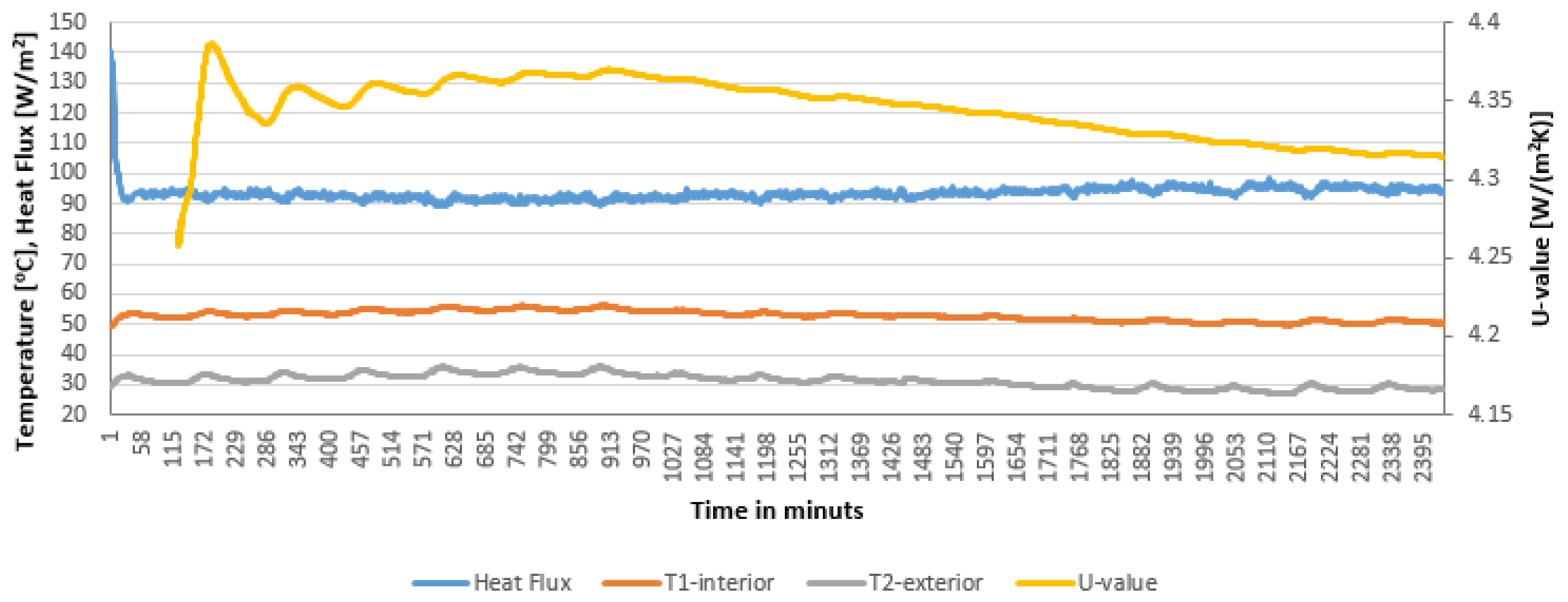
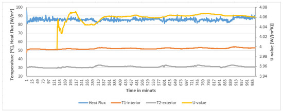
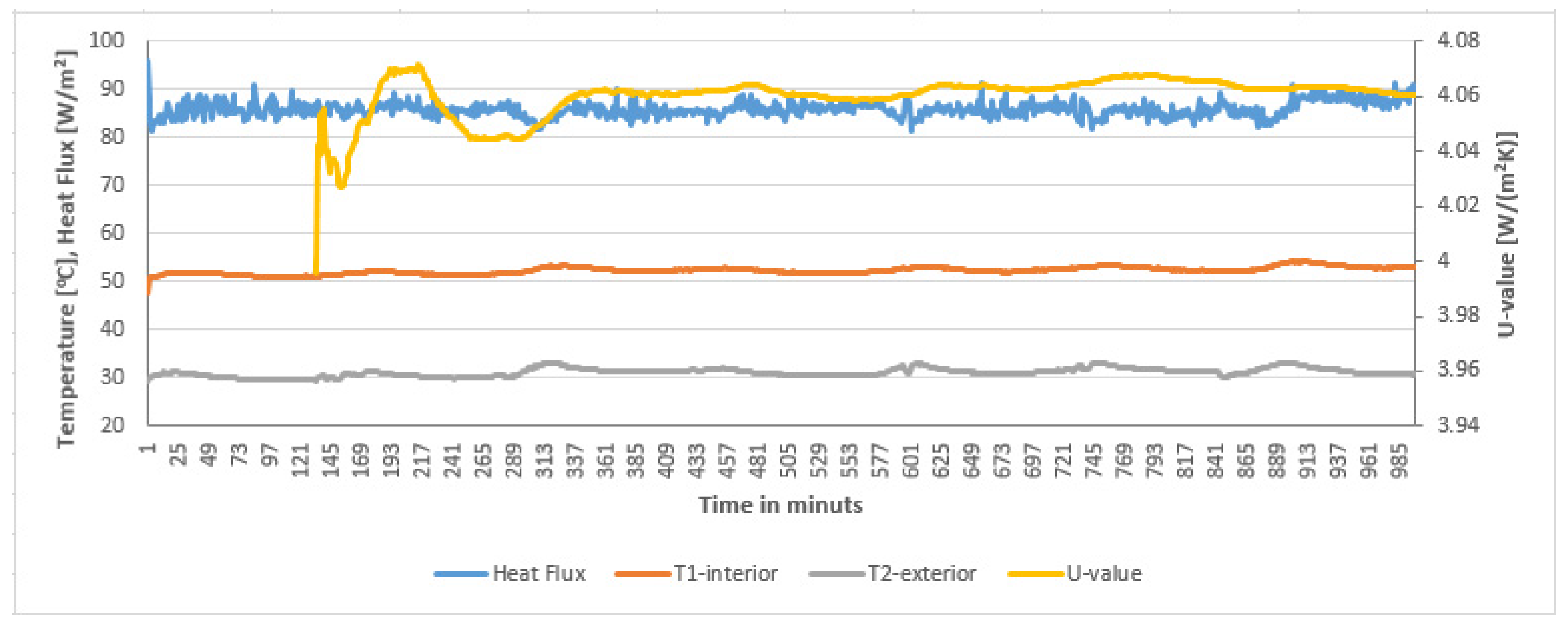
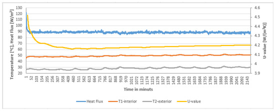
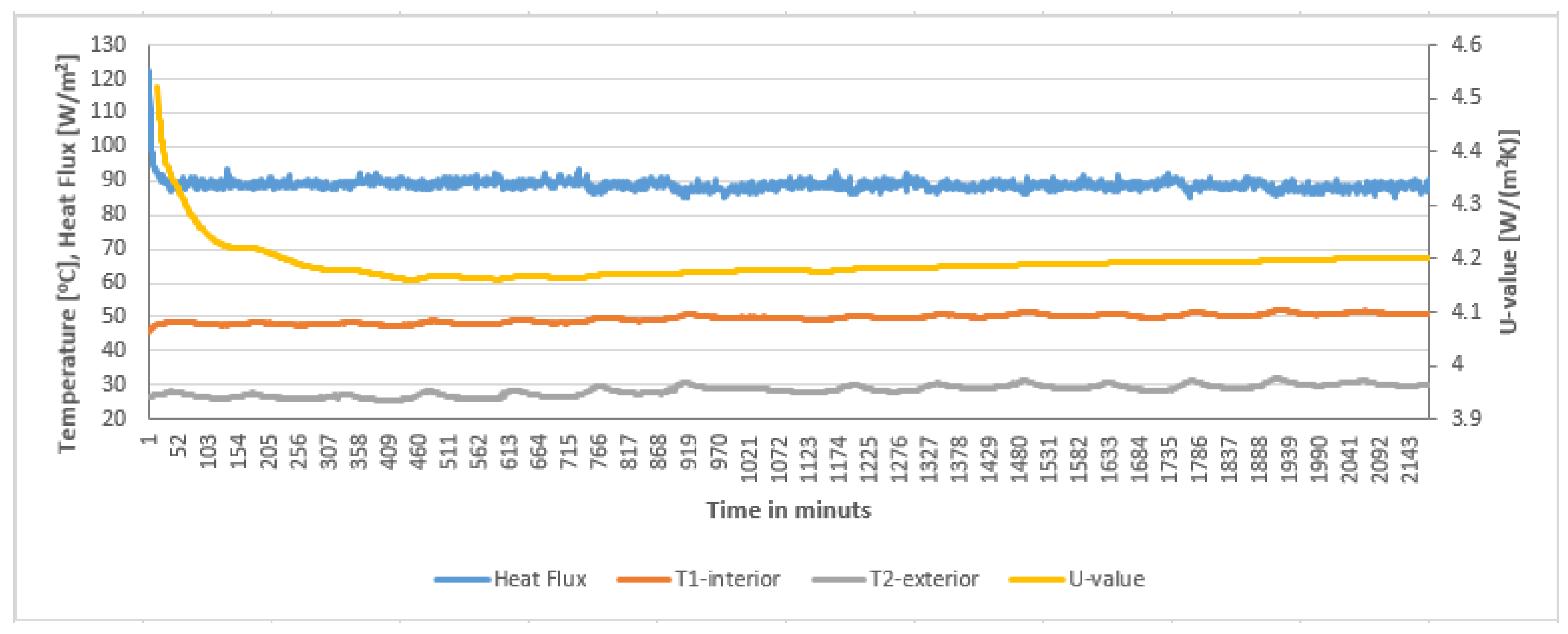
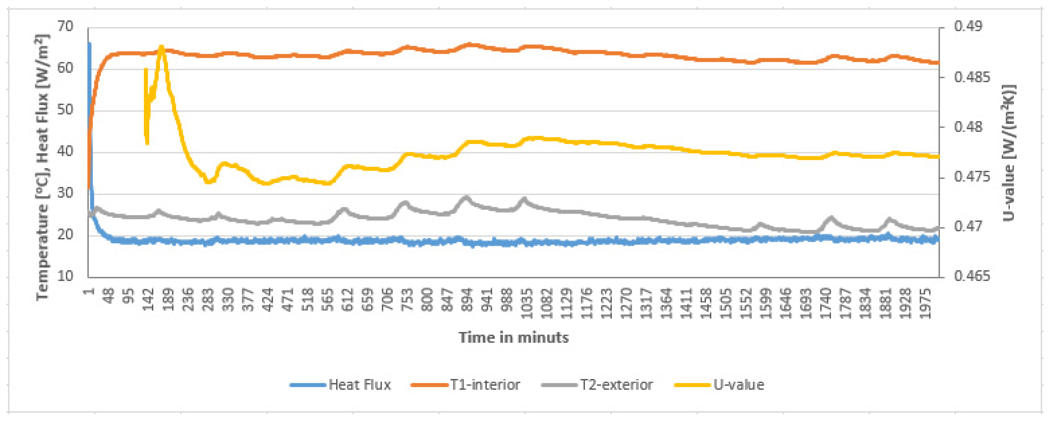
Figure 7, Figure 8, Figure 9, Figure 10, Figure 11 and Figure 12 show the obtained results of heat transfer coefficient measurements and the temperature and heat flux density waveforms on the basis of which this coefficient was determined. Measurement data fulfill the requirements of ISO 9869-1:2014, section 7.1. [82].
Figure 7.
Heat transfer coefficient and temperature and heat flux density curves for gypsum carton board.
Figure 8.
Heat transfer coefficient, temperature, and heat flux density curves for sample P1 coating painted on the inside of the box.
Figure 9.
Heat transfer coefficient, temperature, and heat flux density curves for sample P1 coating painted on the outside.
Figure 10.
Heat transfer coefficient, temperature, and heat flux density curves for sample P2 coating painted on the inside of the box.
Figure 11.
Heat transfer coefficient, temperature, and heat flux density curves for sample P2 coating painted on the outside.
Figure 12.
Heat transfer coefficient, temperature, and heat flux density curves for white polystyrene without coating.
Based on the obtained results presented in Table 3, it can be observed that the heat-protective coating performs better at reflecting thermal radiation than limiting its emission. For P1 coating_inside, the internal temperature was 51.8 °C, the external temperature was 30.3 °C, the heat transfer coefficient reached a value of 4.22 W/(m2∙K), and the measurement uncertainty was 6.05% (similar to the other cases with heat-protective paint coating). When covered with paint from the outside (P1 coating_outside), the internal temperature was 52.8 °C, the external temperature reached 30.3 °C, and the heat transfer coefficient reached 4.31 W/(m2∙K). For the P2 coating_inside, the internal temperature was 52.3 °C, the external temperature reached 31.2 °C, and the heat transfer coefficient had a value of 4.06 W/(m2∙K), while when covered with paint from the outside (P2 coating_outside), the internal temperature was 49.5 °C, the external temperature reached 28.4 °C, and the heat transfer coefficient was 4.20 W/(m2∙K). Table 3 compares the obtained results to the heat transfer coefficient values for a traditional insulating material used in construction (8 cm-thick graphite polystyrene).
Table 3.
Summary of temperatures and heat transfer coefficients of tested samples.
3.3. Results of In Situ Measurements on a Prototype Wall
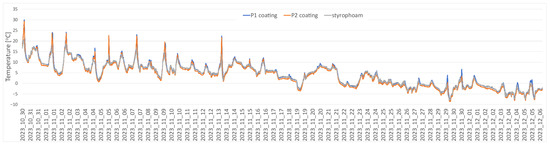
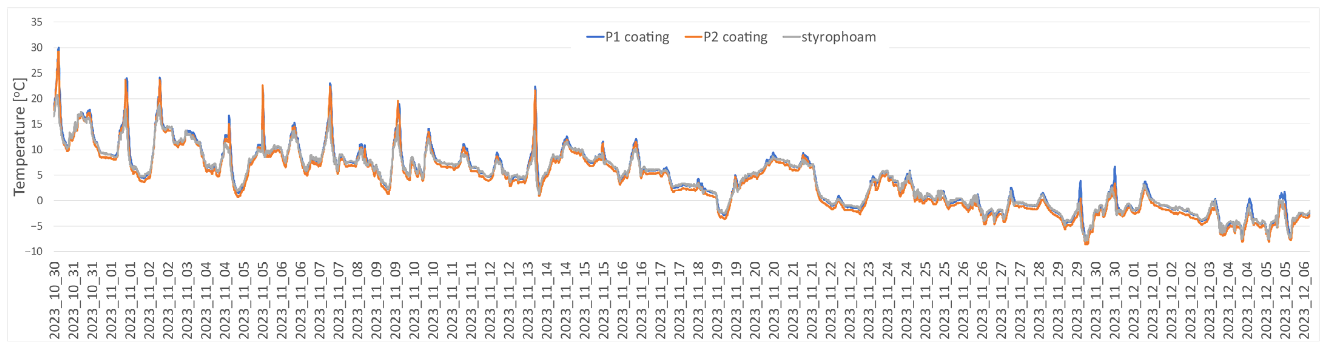
Figure 13 shows the temperature curves recorded on the surface of the facade for the tested paint coatings (P1 coating, P2 coating) and white polystyrene without coating.
Figure 13.
Temperature curves recorded on the surface of the facade for the tested paint coatings (P1 and P2) and white polystyrene without coating.
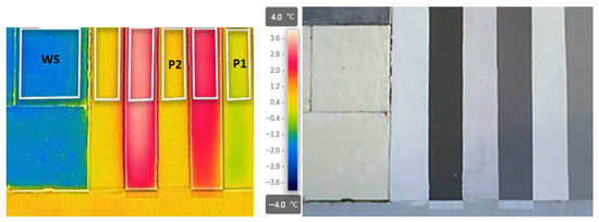
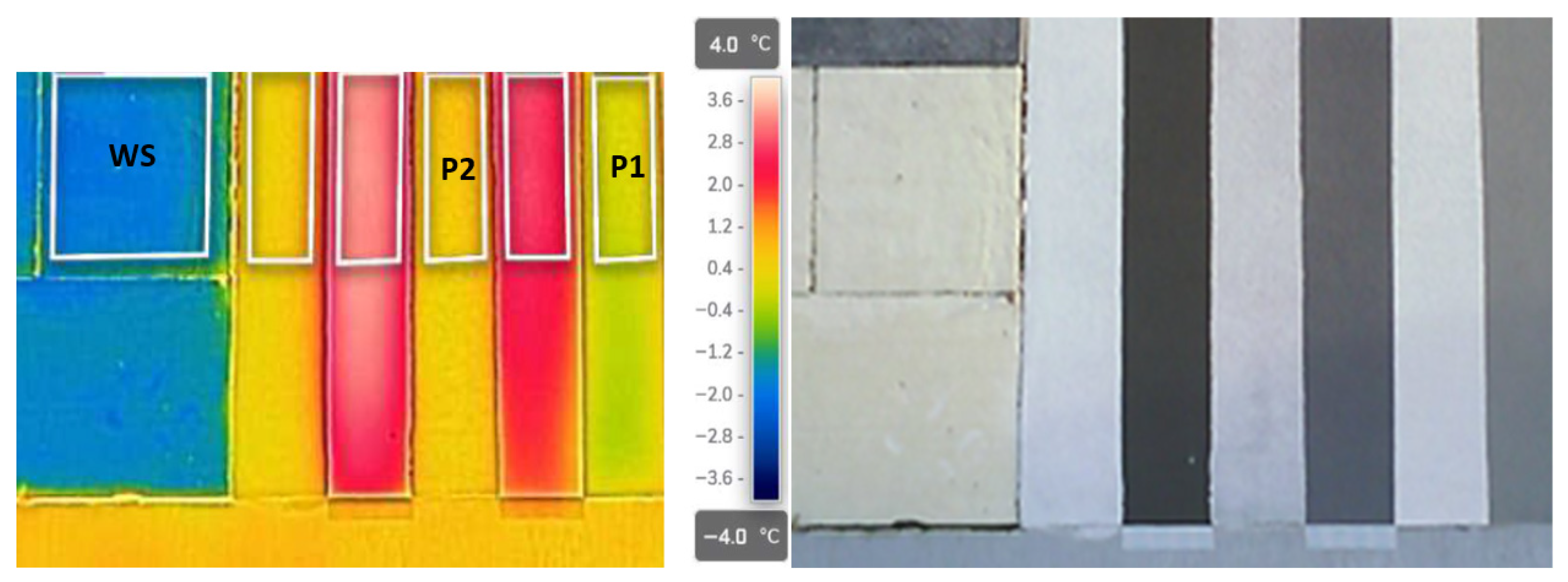
The results of thermographic measurements carried out during the day at an outside air temperature of −3.0 °C, humidity of 78.8%, wind speed of 2 m/s, and solar radiation intensity on the wall of 220 W/m2 are presented in Figure 14. In most cases of external walls of heated buildings located in the climate of Central Europe, thermographic measurements are carried out under conditions of reduced air temperature and the absence of solar radiation. However, due to the determination of the variation in the influence of external environmental conditions on the measurement results of the tested P1 and P2 coatings, the first stage of the tests was performed under direct impact of solar radiation on the surface of the tested wall. The thermogram shows a field marked WS, within which the outer surface is EPS polystyrene in white. The lowest local temperature on the outer surface was recorded in this area, at −2.0 °C. The average temperature in the WS field was slightly lower, at −1.7 °C. The thermogram shows vertical fields with different temperature distributions. The P2 shell was located in the field labeled P2. The average temperature of the outer wall surface in this case was 2.5 °C higher than the average temperature in the WS field (Table 4). In turn, the temperatures obtained in field P1 were 0.6 °C lower than the average temperature in field P2. In the areas between the tested samples, the outer surface was a thin layer of plaster in graphite color, as visible in the photo taken in the visible band (Figure 14). In this case, as expected, the temperature distribution on the darker plastered surfaces indicates a significant increase exceeding 3 °C compared to the analyzed fields with P1 and P2 coatings.
Figure 14.
Thermogram showing the average temperature distributions of the tested samples P1 and P2 during the day under the influence of the sun.
Table 4.
Summary of minimum, maximum, and average temperatures for the samples P1, P2, and WS, tested during the day under the influence of sunlight.
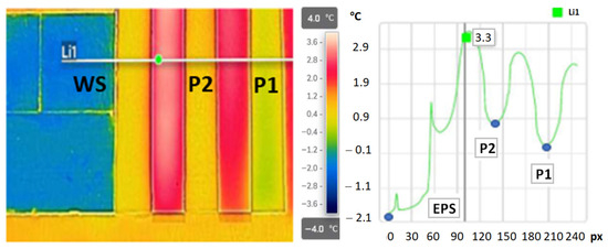
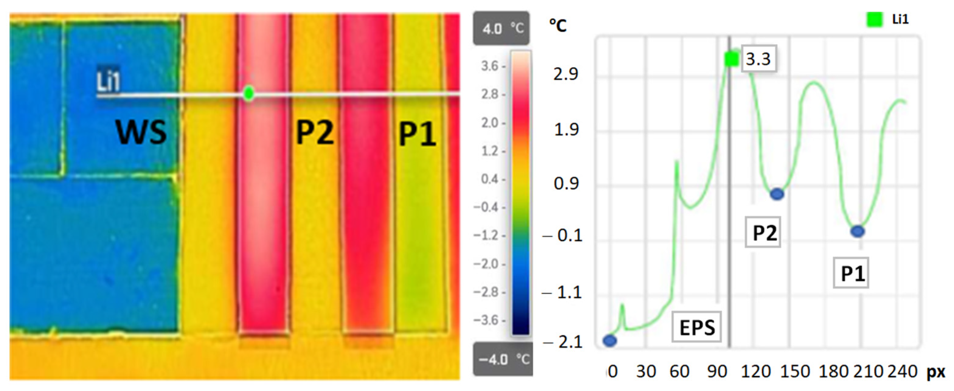
The significant variation in temperature distribution among the tested coatings of P1, P2, and the white EPS polystyrene, which occurred in the tests carried out under conditions of solar radiation and low outside air temperature, is additionally shown in Figure 15. The temperature distribution along the example line Li1 confirms that the lowest temperature, −1.9 °C, was recorded on the EPS polystyrene surface. The minimum recorded temperature along the Li1 line in the P2 coating region was 0.8 °C, and within the P1 coating region, it was 0.2 °C. The temperature distribution along the line indicates that the highest temperature was recorded in the thin-film plaster strip with a solar radiation reflectance HBW of 40. It was more than 3 °C higher than the temperature recorded in the area of coatings P1 and P2. The measurements carried out under unusual external conditions did not show any improvement in the thermal insulation of the P1 and P2 coatings compared to the surface of the unplastered EPS polystyrene.
Figure 15.
Thermogram showing the maximum (3.4 °C), minimum (−1.9 °C), and average (0.9 °C) temperature distributions of the tested samples during the day under the influence of sunlight (during measurement: air temperature −3.0 °C, relative humidity—84%).
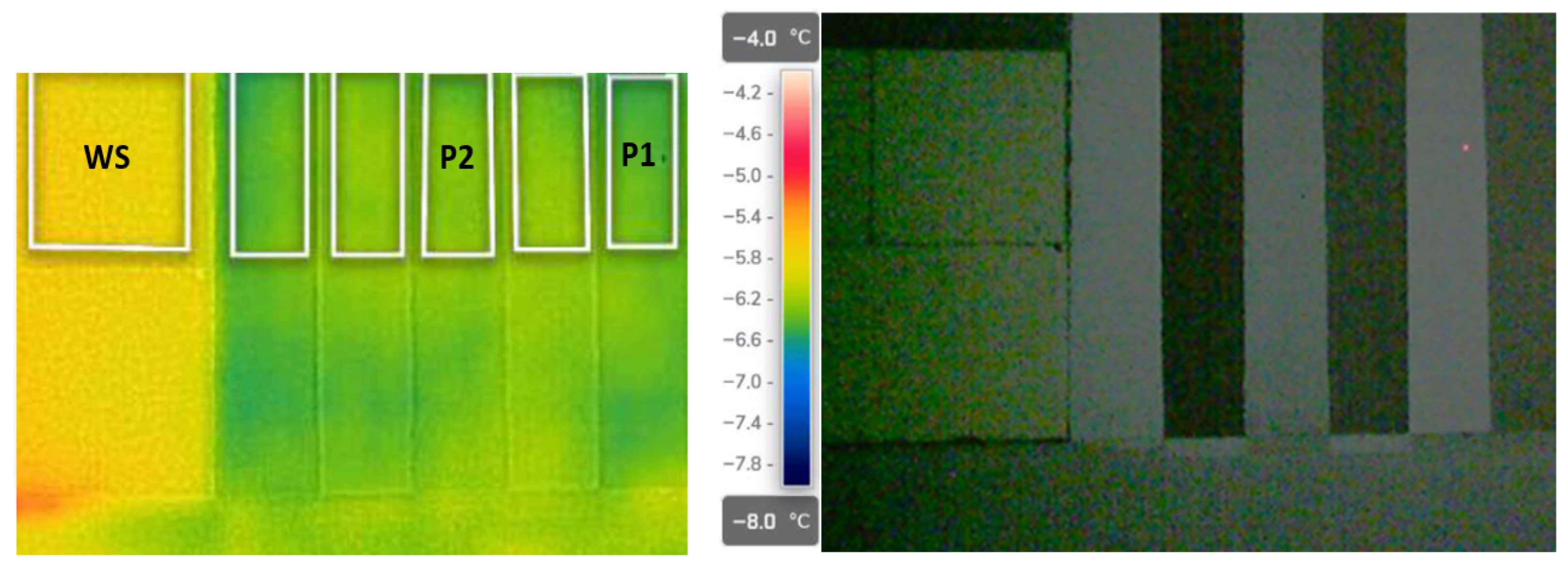
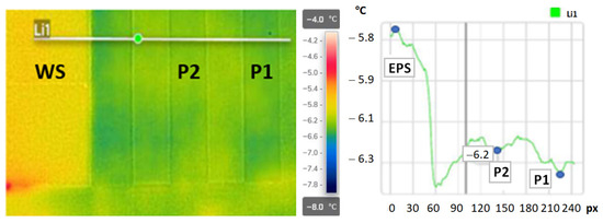
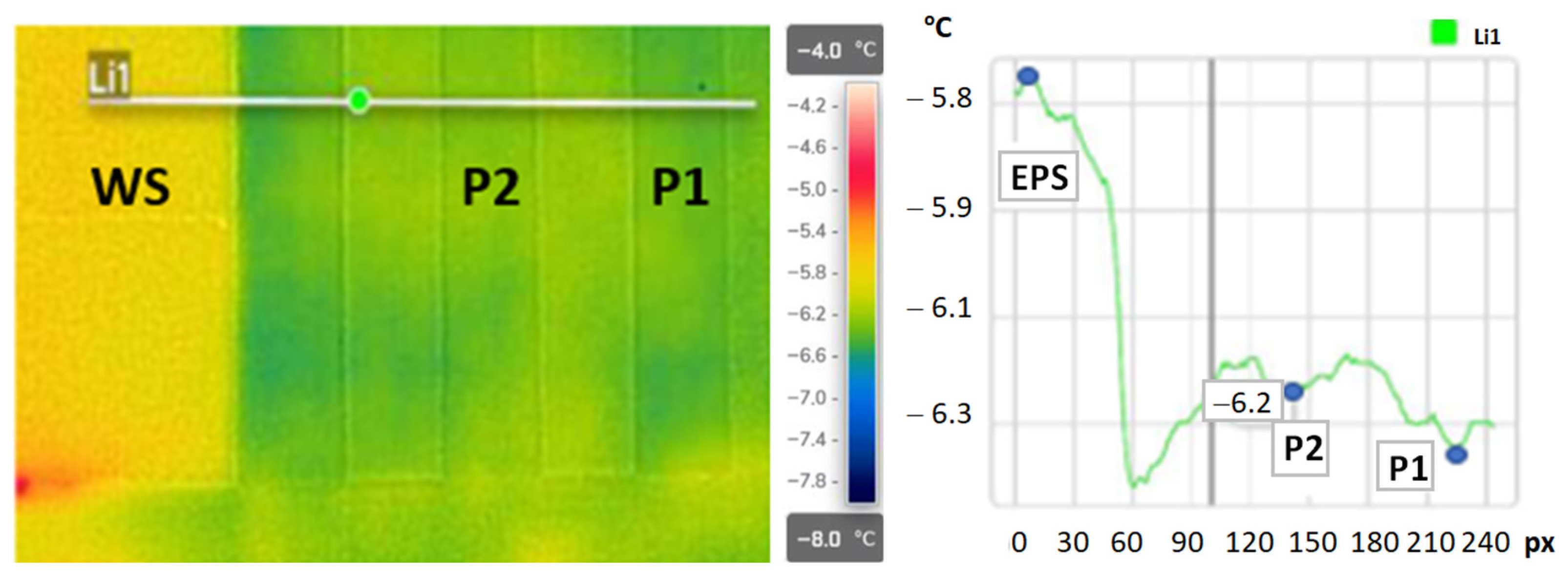
Thermographic studies conducted under typical conditions of reduced outside air temperature and no sun exposure are presented in Figure 16 and Figure 17. The measurements were taken at night at an outside air temperature of −7.5 °C, humidity of 84%, and wind speed of 3.3 m/s. The research results are of a different nature than the results carried out during the day (Figure 14 and Figure 15). Thermograms show a uniform temperature on the outer surface of the wall in the plastered areas. The lowest temperatures on the surface of the external wall were recorded on surfaces covered with paint (Table 5). The average temperatures in fields P1 and P2 were similar and were −6.4 °C and −6.3 °C, respectively (Figure 16). The average WS surface temperature in the analyzed EPS polystyrene field was 0.6 °C higher and amounted to −5.8 °C. Such temperature variation could indicate that the thermal resistance of the P1 and P2 coatings has a significant effect on the temperature distribution on the outer wall surface. In order to verify the above, the temperature was determined along the Li1 line (Figure 17). The temperature distribution determined in the absence of solar radiation (measurements made at night) and low air temperature conditions indicates smaller fluctuations between the minimum temperatures in the P1 and P2 coating areas. The lowest temperature along the Li1 line in the EPS polystyrene region of −5.7 °C is 0.8 °C higher than the minimum temperature reached along the line in the P1 coating region. The temperature distribution along the Li1 line indicates that the lowest temperature within the P2 shell differs by an average of 0.3 °C from the temperature recorded along the Li1 line in the P1 shell region. The temperature distribution along the Li1 line indicates that the highest thermal insulation occurs within the facade finished with the P1 coating. The difference from the plastered adjacent areas without the so-called thermal insulation coating is small and amounts to 0.2 °C. The determined wall surface temperatures in the plastered areas do not indicate a significant improvement in thermal insulation of the P1 and P2 coatings.
Figure 16.
Thermogram showing the average temperature distributions of the tested samples P1 and P2 during the night.
Figure 17.
Thermogram showing the maximum (−5.7 °C), minimum (−6.5 °C), and average (6.2 °C) temperature distributions of the tested samples at night (during measurement: air temperature −7.5 °C, relative humidity—84%).
Table 5.
Summary of minimum, maximum, and average temperatures for the samples P1, P2, and WS tested during the night.
4. Conclusions
The conducted research enabled a multifaceted assessment of the impact of using heat-protective paints on the facades of buildings. The obtained results indicate how important it is to conduct research and analysis on heat-protective paints in terms of their impact on the energy quality of buildings.
According to the authors, the mechanism of action of heat-protective paints is much more difficult to describe than initially predicted. The actual impact of the tested facade coverings on the energy management of the facility seems to be small. Despite manufacturers’ assurances about the effectiveness of using heat-protective paints, it should be noted that the physical basis of the processes describing the operation of these coatings indicates the limited potential of applications of this type of solution in the energy optimization of buildings. The reduction in heat transfer coefficient observed in laboratory tests using a heat meter was small and ranged from 1% to 7%. This confirms the slight influence of the coatings used on improving the thermal insulation of the tested partitions, similarly to the works [64,65]. In situ studies have shown only a minor effect of thermal protective coating on changes in the temperature distribution on the outer wall surface, similar to that shown in [34]. The results of thermographic measurements under the influence of solar radiation showed that thermal protective coating reduces the temperature on the surface of the building partition, similar to what was presented in works [38,44].
Continuation of the research undertaken will allow for the final determination of the thermal parameters of these types of coating.
Based on the obtained analytical results, the authors reached the following conclusions:
- -
- The effect of the tested types of coatings with the addition of microspheres on the heat transfer coefficient of external partitions is very small at the coating thicknesses recommended by the manufacturers.
- -
- The change in the heat transfer coefficient relative to the almost plasterboard covered with heat-protective coatings is in the range of 0.05 to 0.3 W/(m2∙K), depending on the type of coating and the side of the sample covered with paint (interior, exterior).
- -
- Research indicates that covering the internal surfaces of the partition gives better thermal effects.
- -
- This type of covering is characterized by slightly better surface emissivity parameters than typical paint coverings used in construction.
- -
- The influence of this type of covering on the temperatures obtained on the surface of partitions is also small for the typically occurring temperatures on facades.
- -
- In situ measurements carried out on the partition in the natural environment indicate a slight effect of surface temperature reduction by the tested coverings. Comparison with a fragment of the wall covered with white polystyrene, without an external expedition, shows that temperature values during periods of increased solar radiation intensity are usually the lowest for the white polystyrene surface.
The genesis of the applications of this type of heat-protective coating in industry concerns much higher temperature ranges, where these types of materials can show a greater effect on significantly reducing the surface temperature. The use of thermoprotective coverings for building protection is a much less effective solution due to the lower temperature range. Despite the known physical basis, the economic aspects of using this type of covering call into question the meaning of this type of activity. In comparative studies, the 8 cm graphite polystyrene layer used improves the heat transfer coefficient by approximately eight times compared to the heat-protective coatings used.
The research concerned the technical application of heat-protective paints in construction. Specifically, their influence on the thermal resistance of the partition and the heat transfer coefficient. The conclusions drawn apply only to the tested paint ranges. For other products, similar studies would have to be carried out. It can be assumed that similar effects will be obtained for coatings with the same structure (microspheres immersed in an opaque binder).
Due to ongoing climate change, protecting buildings from overheating is becoming increasingly important. Excessive energy gains caused by solar radiation can negatively impact the structure of roofing materials and the energy balance of a building, including the need for cooling. The use of heat-protective coatings on roof surfaces could contribute to improving the working conditions of the partition and the energy balance of the building in such situations.
This article is innovative because it goes beyond traditional materials used in construction and focuses on the use of materials that incorporate nanotechnology. Moreover, in relation to the material and structural solutions typically used in construction, the approach to incorporating the discussed thermal insulation layers into the partition structure is different and innovative. By painting the surface, the application expands the possibilities of using this type of solution in difficult cases, e.g., dimensional and cubic limitations related to the location of the object in the field.
For the first time, the effectiveness of thermo paints was verified under real-world conditions of use of a building located in Upper Silesia.
Thermal insulation coatings based mainly on reflectance do not show a significant improvement in the thermal insulation of external walls in a building located in the climatic conditions of Upper Silesia.
Short-term differences in wall surface temperature, especially during periods of solar radiation exposure, are related to the increased reflectivity of the coatings. Under real conditions of reduced outside air temperature, the thermo coatings used in the tests do not significantly increase the thermal resistance of the external walls, which could have a noticeable impact on the energy demand for heating purposes of buildings located in the climate of Central Europe.
The test results made it possible to verify the effectiveness of the coatings as thermal insulation for external walls under both real and laboratory conditions. To date, the use of thermo coatings as additional insulation on insulated external walls in the ETICS system has not been verified. The use of an additional potential thermal insulation layer in the form of a thermo coating did not demonstrate its effectiveness. Both contact measurements using temperature sensors and thermographic measurements showed no significant changes in the temperature distribution in the wall that could effectively improve the thermal resistance of the building partition.
Author Contributions
Conceptualization, P.K., J.B., B.W.-S. and M.M.; methodology, P.K., J.B., B.W.-S. and M.M.; validation, R.N.; formal analysis, J.B., B.W.-S., M.M. and P.K.; investigation, M.G., P.K., J.B., B.W.-S. and M.M.; data curation, J.B., B.W.-S. and M.M.; writing—original draft preparation, M.M., B.W.-S. and M.S.; writing—review and editing, R.N., P.K., J.B., B.W.-S., M.M. and M.S.; visualization, M.G. and M.M. All authors have read and agreed to the published version of the manuscript.
Funding
This research received no external funding.
Data Availability Statement
The original contributions presented in this study are included in the article. Further inquiries can be directed to the corresponding authors.
Conflicts of Interest
The authors declare no conflicts of interest.
References
- European Parliament; Council of the European Union. Directive (EU) 2024/1275 of the European Parliament and of the Council of 24 April 2024 on the Energy Performance of Buildings (Recast). Official Journal of the European Union, 2024. Available online: http://data.europa.eu/eli/dir/2024/1275/oj (accessed on 15 November 2025).
- Available online: https://www.consilium.europa.eu/en/policies/fit-for-55/ (accessed on 15 November 2025).
- Construction Law Act. Available online: https://isap.sejm.gov.pl/isap.nsf/DocDetails.xsp?id=wdu19940890414 (accessed on 15 November 2025).
- Regulation of the Minister of Infrastructure on the Technical Conditions to be Met by Buildings and Their Location. Available online: https://isap.sejm.gov.pl/isap.nsf/download.xsp/WDU20220001225/O/D20221225.pdf (accessed on 15 November 2025).
- Regulation of the Minister of Infrastructure and Development of 27 February 2015, pos. 376 on the Methodology for Determining the Energy Performance of a Building or Part of a Building and Energy Performance Certificates. Available online: https://isap.sejm.gov.pl/isap.nsf/DocDetails.xsp?id=WDU20150000376 (accessed on 15 November 2025).
- Available online: https://www.sejm.gov.pl/prawo/konst/polski/kon1.htm (accessed on 15 November 2025).
- Liua, S.; Zhua, K.; Cui, S.; Shena, X.; Tanc, G. A novel building material with low thermal conductivity: Rapid synthesis of foam concrete reinforced silica aerogel and energy performance simulation. Energy Build. 2018, 177, 385–393. [Google Scholar] [CrossRef] [Scilit]
- Yanga, W.; Liua, J.; Wanga, Y.; Gao, S. Experimental study on the thermal conductivity of aerogel-enhanced insulating materials under various hygrothermal environments. Energy Build. 2020, 206, 109583. [Google Scholar] [CrossRef] [Scilit]
- Zhang, T.; Zhang, Y.; Zhu, H.; Yan, Z. Experimental investigation and multi-level modeling of the effective thermal conductivity of hybrid micro-fiber reinforced cementitious composites at elevated temperatures. Compos. Struct. 2021, 26, 112988. [Google Scholar] [CrossRef] [Scilit]
- Pásztorya, Z.; Horváthc, T.; Glass, S.V.; Zelinka, S. Experimental investigation of the influence of temperature on thermal conductivity of multilayer reflective thermal insulation. Energy Build. 2018, 174, 26–30. [Google Scholar] [CrossRef] [Scilit]
- Liua, H.; Hua, M.; Jiaoa, J.; Li, Z.; Wua, X. Effective thermal conductivity modeling of hollow nanosphere packing structures. Int. J. Heat Mass Transf. 2020, 161, 120298. [Google Scholar] [CrossRef] [Scilit]
- Huang, J.; Xia, X.; Hu, X.; Li, S.; Liu, K. A general method for measuring the thermal conductivity of MOF crystals. Int. J. Heat Mass Transf. 2019, 138, 11–16. [Google Scholar] [CrossRef] [Scilit]
- Wang, H.; Hou, F.; Chang, C. Experimental and computational modeling of thermal conductivity of cementitious syntactic foams filled with hollow glass microspheres. Constr. Build. Mater. 2020, 265, 120739. [Google Scholar] [CrossRef] [Scilit]
- Zhang, C.; Zhang, C.; Huang, R.; Gu, X. Effects of hollow microspheres on the thermal insulation of polysiloxane foam. J. Appl. Polym. Sci. 2017, 134, 18. [Google Scholar] [CrossRef] [Scilit]
- Hu, Y.; Mei, R.; An, Z.; Zhang, J. Silicon rubber/hollow glass microsphere composites: Influence of broken hollow glass microsphere on mechanical and thermal insulation property. Compos. Sci. Technol. 2013, 79, 64–69. [Google Scholar] [CrossRef] [Scilit]
- Shao, N.; Zhang, Y.; Liu, Z.; Wang, D.; Zhang, Z. Fabrication of hollow microspheres filled fly ash based foam geopolymers with ultra-low thermal conductivity and relative high strength. Constr. Build. Mater. 2018, 185, 567–573. [Google Scholar] [CrossRef] [Scilit]
- Shen, Z.; Brooks, A.L.; He, Y.; Shrestha, S.S.; Zhou, H. Evaluating dynamic thermal performance of building envelope components using small-scale calibrated hot box tests. Energy Build. 2021, 251, 111342. [Google Scholar] [CrossRef] [Scilit]
- Barbaresi, A.; Bovo, M.; Santolini, E.; Barbaresi, L.; Torreggiani, D.; Tassinari, P. Development of a low-cost movable hot box for a preliminary definition of the thermal conductance of building envelopes. Build. Environ. 2020, 180, 107034. [Google Scholar] [CrossRef] [Scilit]
- Cao, X.; Tang, B.; Zou, X.; He, L. Analysis on the cooling effect of a heat-reflective coating for asphalt pavement. Road Mater. Pavement Des. 2015, 16, 716–726. [Google Scholar] [CrossRef] [Scilit]
- Bao, Y.; Kang, Q.L.; Ma, J.Z. Structural regulation of hollow spherical TiO2 by varying titanium source amount and their thermal insulation property. Colloids Surf. A Physicochem. Eng. Asp. 2018, 537, 69–75. [Google Scholar] [CrossRef] [Scilit]
- Synnefa, A.; Santamouris, M.; Akbari, H. Estimating the effect of using cool coatings on energy loads and thermal comfort in residential buildings in various climatic conditions. Energy Build. 2007, 39, 1167–1174. [Google Scholar] [CrossRef] [Scilit]
- Joudi, A.; Svedung, H.; Cehlin, M.; Rönnelid, M. Reflective coatings for interior and exterior of buildings and improving thermal performance. Appl. Energy 2013, 103, 562–570. [Google Scholar] [CrossRef] [Scilit]
- Wang, F.; Liang, J.; Tang, Q.; Wang, N.; Li, L. Preparation and Properties of Thermal Insulation Latex Paint for Exterior Wall Based on Defibred Sepiolite and Hollow Glass Microspheres. Adv. Mater. Res. 2009, 58, 103–108. [Google Scholar] [CrossRef] [Scilit]
- Nowoświat, A.; Miros, A.; Krause, P. Change in the properties of expanded polystyrene exposed to solar radiation in real aging conditions. Sustainability 2024, 16, 7320. [Google Scholar] [CrossRef] [Scilit]
- Norvaisiene, R.; Krause, P.; Buhagiar, V.; Burlingis, A. Resistance of ETICS with fire barriers to cyclic hygrothermal impact. Sustainability 2021, 13, 9220. [Google Scholar] [CrossRef] [Scilit]
- Liu, Z.; Yao, Z.; Lv, Z.; Huo, Z.; Tan, S.; Guo, S.; Qin, Y. Structural and thermal enhancemnets in hollow glass microspheres via ZnO nanoparticle coating. J. Coat. Technol. Res. 2025, 22, 1995–2007. [Google Scholar] [CrossRef] [Scilit]
- Herrera-Ramírez, L.C.; Cano, M.; Guzman de Villoria, R. Low thermal and high electrical conductivity in hollow glass microspheres covered with carbon nanofiber–polymer composites. Compos. Sci. Technol. 2017, 151, 211–218. [Google Scholar] [CrossRef] [Scilit]
- Qian, H.; Bismarck, A.; Greenhalgh, E.S.; Shaffer, M.S.P. Synthesis and characterisation of carbon nanotubes grown on silica fibres by injection CVD. Carbon 2010, 48, 277–286. [Google Scholar] [CrossRef] [Scilit]
- Wicks, S.S.; de Villoria, R.G.; Wardle, B.L. Interlaminar and intralaminar reinforcement of composite laminates with aligned carbon nanotubes. Compos. Sci. Technol. 2010, 70, 20–28. [Google Scholar] [CrossRef] [Scilit]
- Yamamoto, N.; Hart, A.J.; Garcia, E.J.; Wicks, S.S.; Duong, H.M.; Slocum, A.H.; Wardle, B.L. High-yield growth and morphology control of aligned carbon nanotubes on ceramic fibers for multifunctional enhancement of structural composites. Carbon 2009, 47, 551–560. [Google Scholar] [CrossRef] [Scilit]
- Król, D.; Motyl, P.; Piotrowska-Woroniak, J.; Patej, M.; Poskrobko, S. Heat Reflective Thin-Film Polymer Insulation with Polymer Nanospheres—Determination of Thermal Conductivity Coefficient. Energies 2022, 15, 6286. [Google Scholar] [CrossRef] [Scilit]
- Malewska, E.; Prociak, A.; Vevere, L.; Vanags, E.; Zemła, M.; Uram, K.; Kirpluks, M.; Cabulis, U.; Bryk, M. New Thermo-Reflective Coatings for Applications as a Layer of Heat Insulating Materials. Materials 2022, 15, 5642. [Google Scholar] [CrossRef] [Scilit]
- Shang, J.; Wang, M.; Wang, P.; Li, G.; Yang, M.; Li, Y. Study on Thermal Reflection Characteristics of Composite Inorganic Coatings. Appl. Sci. 2024, 14, 6898. [Google Scholar] [CrossRef] [Scilit]
- Simpson, A.; Fitton, R.; Rattigan, I.G.; Marshall, A.; Parr, G.; Swan, W. Thermal performance of thermal paint and surface coatings in buildings in heating dominated climates. Energy Build. 2019, 197, 196–213. [Google Scholar] [CrossRef] [Scilit]
- Yu, Z.; Du, X.; Zhu, P.; Zhao, T.; Sun, R.; Chen, J.; Wang, N.; Li, W. Surface modified hollow glass microspheres-epoxy composites with enhanced thermal insulation and reduced dielectric constant. Mater. Today Commun. 2022, 32, 104046. [Google Scholar] [CrossRef] [Scilit]
- Calovi, M.; Rossi, S. Durability and Thermal Behavior of Functional Paints Formulated with Recycled-Glass Hollow Microspheres of Different Size. Materials 2023, 16, 2678. [Google Scholar] [CrossRef] [Scilit]
- Peng, J.; Lai, J.-C.; Xiao, X.; Jin, W.; Zhou, J.; Yang, Y.; Gao, X.; Tang, J.; Fan, L.; Shanhui, F.; et al. Colorful low-emissivity paints for space heating and cooling energy savings. Proc. Natl. Acad. Sci. USA 2023, 120, e2300856120. [Google Scholar] [CrossRef] [Scilit]
- Kwon, T.K.; Zoh, H.D.; Ahn, W.; Lee, S.; Kim, T.H. Analysis of Indoor Thermal Environment Improvement in Apartment Buildings Through the Application of Heat-Reflective Paint. Buildings 2024, 14, 3834. [Google Scholar] [CrossRef] [Scilit]
- Farkoush, M.A.; Rashidi, A.; Alaei, M. Thermal insulation of water-based acrylic coatings reinforced with APTES-functionalized silica fume nanoparticles. Sci. Rep. 2026, 16, 2361. [Google Scholar] [CrossRef] [Scilit]
- Bozsaky, D. Laboratory Tests with Liquid Nano-ceramic Thermal Insulation Coating. Procedia Eng. 2015, 123, 68–75. [Google Scholar] [CrossRef] [Scilit]
- Bozsaky, D. Thermal insulation with nanotechnology-based materials. In Proceedings of the Internationales Symposium Eventmaterials, Wien, Austria, 19–20 November 2015; pp. 137–154. [Google Scholar]
- Bozsaky, D. Recent studies on thermodynamic processes in nano-ceramic thermal insulation coatings. Pollack Period. 2019, 14, 107–116. [Google Scholar] [CrossRef] [Scilit]
- Bozsaky, D. Thermodynamic tests with nano-ceramic thermal insulation coatings. Pollack Period. 2017, 12, 135–145. [Google Scholar] [CrossRef] [Scilit]
- Paul, G.; Chopkar, M.; Manna, I.; Das, P.K. Techniques for measuring the thermal conductivity of nanofluids: A review. Renew. Sustain. Energy Rev. 2010, 14, 1913–1924. [Google Scholar] [CrossRef] [Scilit]
- Pisello, A.L.; Goretti, M.; Cotana, F. A method for assessing buildings’ energy efficiency by dynamic simulation and experimental activity. Appl. Energy 2012, 47, 419–429. [Google Scholar] [CrossRef] [Scilit]
- Jo, J.H.; Carlson, J.D.; Golden, J.S.; Bryan, H. An integrated empirical and modeling methodology for analyzing solar reflective roof technologies on commercial buildings. Build. Environ. 2010, 45, 453–460. [Google Scholar] [CrossRef] [Scilit]
- Wray, C.; Akbari, H. The effects of roof reflectance on air temperatures surrounding a rooftop condensing unit. Energy Build. 2008, 40, 11–28. [Google Scholar] [CrossRef] [Scilit]
- Wang, X.X.; Kendrick, C.; Ogden, R.; Maxted, J. Dynamic thermal simulation of a retail shed with solar reflective coatings. Appl. Therm. Eng. 2008, 28, 1066–1073. [Google Scholar] [CrossRef] [Scilit]
- Zinzi, M.; Fasano, G. Properties and performance of advanced reflective paints to reduce the cooling loads in buildings and mitigate the heat island effect in urban areas. Int. J. Sustain. Energy 2009, 28, 123–139. [Google Scholar] [CrossRef] [Scilit]
- Moujaes, S.F.; Brickman, R. Thermal performance analysis of highly reflective coating on residences in hot and arid climates. J. Energy Eng. 2003, 129, 56–68. [Google Scholar] [CrossRef] [Scilit]
- Suehrcke, H.; Peterson, E.L.; Selby, N. Effect of roof solar reflectance on the building heat gain in a hot climate. Energy Build. 2008, 40, 2224–2235. [Google Scholar] [CrossRef] [Scilit]
- Kokogiannakis, G.; Tuohy, P.; Darkwa, J. Impact of material surface properties on building performance across a variety of climates. Int. J. Low Carbon Technol. 2012, 7, 181–186. [Google Scholar] [CrossRef] [Scilit]
- Synnefa, A.; Saliari, M.; Santamouris, M. Experimental and numerical assessment of the impact of increased roof reflectance on a school building in Athens. Energy Build. 2012, 55, 7–15. [Google Scholar] [CrossRef] [Scilit]
- Guo, W.; Qiao, X.; Huang, Y.; Fang, M.; Han, X. Study on energy saving effect of heat-reflective insulation coating on envelopes in the hot summer and cold winter zone. Energy Build. 2012, 50, 196–203. [Google Scholar] [CrossRef] [Scilit]
- Levinson, R.; Akbari, H.; Reilly, J.C. Cooler tile-roofed buildings with near-infrared-reflective non-white coatings. Build. Environ. 2007, 42, 2591–2605. [Google Scholar] [CrossRef] [Scilit]
- Synnefa, A.; Santamouris, M.; Apostolakis, K. On the development, optical properties and thermal performance of cool colored coatings for the urban environment. Sol. Energy 2007, 81, 488–497. [Google Scholar] [CrossRef] [Scilit]
- Uemoto, L.K.; Sato, N.M.N.; John, V.M. Estimating thermal performance of cool colored paints. Energy Build. 2010, 42, 17–22. [Google Scholar] [CrossRef] [Scilit]
- Santamouris, M.; Gaitani, N.; Spanou, A.; Saliari, M.; Giannopoulou, K.; Vasilakopoulou, K.; Kardomateas, T. Using cool paving materials to improve microclimate of urban areas–Design realization and results of the flisvos project. Build. Environ. 2012, 53, 128–136. [Google Scholar] [CrossRef] [Scilit]
- Synnefa, A.; Karlessi, T.; Gaitani, N.; Santamouris, M.; Assimakopoulos, D.N.; Papakatsikas, C. Experimental testing of cool colored thin layer asphalt and estimation of its potential to improve the urban microclimate. Build. Environ. 2011, 46, 38–44. [Google Scholar] [CrossRef] [Scilit]
- Joudi, A.; Harald Svedung, H.; Rönnelid, M. Energy efficient surfaces on building sandwich panels—A dynamic simulation model. Energy Build. 2011, 43, 2462–2467. [Google Scholar] [CrossRef] [Scilit]
- Joudi, A.; Svedung, H.; Bales, C.; Rönnelid, M. Highly reflective coatings for interior and exterior steel cladding and the energy efficiency of buildings. Appl. Energy 2011, 88, 4655–4666. [Google Scholar] [CrossRef] [Scilit]
- Achar, S.; Procopio, L.J. Developments in waterborne thermal insulation coatings. J. Prot. Coat. Linings 2013, 30, 48–59. [Google Scholar]
- Sahu, P.; Mahanwar, P.; Bambole, V. Effect of hollow glass microspheres and cenospheres on insulation properties of coatings. Pigment. Resin Technol. 2013, 42, 223. [Google Scholar] [CrossRef] [Scilit]
- Čekon, M. Thermodynamic Properties of Reflective Coatings. Adv. Mater. Res. 2013, 649, 179–182. [Google Scholar] [CrossRef] [Scilit]
- Čekon, M.; Kalousek, M.; Hraška, J.; Ingeli, R. Spectral optical properties and thermodynamic performance of reflective coatings in a mild climate zone. Energy Build. 2014, 77, 343–354. [Google Scholar] [CrossRef] [Scilit]
- Synnefa, A.; Santamouris, M.; Livada, I. A study of the thermal performance of reflective coatings for the urban environment. Sol. Energy 2006, 80, 968–981. [Google Scholar] [CrossRef] [Scilit]
- de Brito Filho, J.P.; Henriquez, J.R.; Dutra, J.C.C. Effects of coefficients of solar reflectivity and infrared emissivity on the temperature and heat flux of horizontal flat roofs of artificially conditioned nonresidential buildings. Energy Build. 2011, 43, 440–445. [Google Scholar] [CrossRef] [Scilit]
- Berdahl, P.; Bretz, S.E. Preliminary survey of the solar reflectance of cool roofing materials. Energy Build. 1997, 25, 149–158. [Google Scholar] [CrossRef] [Scilit]
- Shen, H.; Tan, H.; Tzempelikos, A. The effect of reflective coatings on building surface temperatures, indoor environment and energy consumption—An experimental study. Energy Build. 2011, 43, 573–580. [Google Scholar] [CrossRef] [Scilit]
- Akbari, H.; Konopacki, S. Calculating energy-saving potentials of heat-island reduction strategies. Energy Policy 2005, 33, 721–756. [Google Scholar] [CrossRef] [Scilit]
- Ichinose, M.; Inoue, T.; Sakamoto, Y. Long-term performance of high-reflectivity exterior panels. Build. Environ. 2009, 44, 1601–1608. [Google Scholar] [CrossRef] [Scilit]
- Jia, M.Q.; Jin, Y.H. Performance of Thermal Insulation Reflective Composite Coatings. Adv. Mater. Res. 2011, 239–242, 1771–1774. [Google Scholar] [CrossRef] [Scilit]
- Song, Z.; Zhang, W.; Shi, Y.; Song, J.; Qu, J.; Qin, J.; Zhang, T.; Li, Y.; Zhang, H.; Zhang, R. Optical properties across the solar spectrum and indoor thermal performance of cool white coatings for building energy efficiency. Energy Build. 2013, 63, 49–58. [Google Scholar] [CrossRef] [Scilit]
- Available online: https://www.tri-color.pl/spektrofotometry-przenosne/sv300 (accessed on 15 April 2026).
- Gawełek, M. Research and Analysis of Thermal Insulation Coatings Used in the Construction Industry. Master’s Thesis, Silesian University of Technology, Gliwice, Poland, 2024. [Google Scholar]
- ASTM E903-20; Standard Test Method for Solar Absorptance, Reflectance, and Transmittance of Materials Using Integrating Spheres. ASTM International: West Conshohocken, PA, USA, 2020.
- ASTM E1980-24; Standard Practice for Calculating Solar Reflectance Index of Horizontal and LowSloped Opaque Surfaces. ASTM International: West Conshohocken, PA, USA, 2024.
- Murzyn, P. Raport z Badań: Wyznaczenie Współczynnika Przewodzenia Ciepła λ Materiału o Nazwie: Cienkowarstwowa Powłoka Termoizolacyjna. KrakóW 2023. Available online: https://akterm.tech/images/certyfikaty/AGH.pdf (accessed on 5 May 2026).
- Klemm, P.; Chwieduk, D.; Francke, B.; Grabarczyk, S.; Klemm, P.; Kosiorek, M.; Kubik, J.; Pogorzelski, J.A.; Szudrowicz, B.; Ścisłewski, Z.; et al. Budownictwo Ogólne T2–Fizyka Budowli; Arkady: Warszawa, Poland, 2005. [Google Scholar]
- Więcek, B.; May, G. Termowizja w Podczerwieni. Podstawy i Zastosowania; Wydawnictwo PAK: Warsaw, Poland, 2011. [Google Scholar]
- Pudlik, W. Wymiana i Wymienniki Ciepła; Politechnika Gdańska: Gdańsk, Poland, 2012. [Google Scholar]
- ISO 9869-1:2014; Thermal Insulation—Building Elements—In-Situ Measurement of Thermal Resi-Stance and Thermal Transmittancepart 1: Heat Flow Meter Method. ISO: Geneva, Switzerland, 2014.
- Mokrzycki, W.; Tatol, M. Color difference ΔE―A Survey. Mach. Graph. Vis. 2011, 20, 383–411. [Google Scholar]


Disclaimer/Publisher’s Note: The statements, opinions and data contained in all publications are solely those of the individual author(s) and contributor(s) and not of MDPI and/or the editor(s). MDPI and/or the editor(s) disclaim responsibility for any injury to people or property resulting from any ideas, methods, instructions or products referred to in the content. |
© 2026 by the authors. Licensee MDPI, Basel, Switzerland. This article is an open access article distributed under the terms and conditions of the Creative Commons Attribution (CC BY) license.