


Abstract
Contactless transmission of mechanical power, which is characteristic of coaxial magnetic gears (CMGs), offers significant advantages over conventional mechanical gears, in particular, reduced maintenance frequency and inherent overload protection. At the same time, there is a lack of design methodologies for this type of gear based on the analysis and systematization of experience gained from already implemented designs. This paper presents a method for determining the maximum magnetic torques of CMGs on the basis of an equivalent magnetic-circuit model. The error associated with the proposed methodology does not exceed ±15%, which enables the influence of geometric parameters and the magnetic properties of materials on the key performance indicators of the gear to be assessed already at the preliminary design stage. A mathematical model of CMG dynamics was also developed, based on a quasi-stationary two-dimensional approximation of the magnetic field, accounting for the geometry of the magnetic circuit, the spatial distribution of the magnetic vector potential, and magnetic-circuit saturation. The proposed mathematical model was verified using the results of physical experiments. The discrepancy between the calculated and experimental values of the torque on the low-speed shaft in the steady state does not exceed 5.5%. Based on the optimization procedure, the dependence of the maximum linear torque density on the outer diameter of the CMG, the number of poles of the high-speed rotor, and the transmission ratio was determined. It was shown that, as the number of poles increases, the linear torque density also increases and, for example, for diameters of approximately 800 mm, it may exceed 100 N·m/m.
1. Introduction
Mechanical power transmission, both with speed increase and with speed reduction, is a typical function required for the operation of most mechanisms. Traditionally, it has been implemented by various types of mechanical transmissions—gearboxes or speed multipliers. However, beginning in the late 1960s, together with advances in materials science and the development of magnetically hard rare-earth materials, so-called magnetic gears began to be intensively investigated as an alternative to mechanical gears. This solution offers a number of important advantages compared with its mechanical counterpart. In particular, there is no mechanical contact between the input and output shafts, no need for lubrication or periodic maintenance, relatively lower noise and vibration levels, and the possibility of operation in aggressive or explosive environments. Moreover, compared with single-stage toothed gears, magnetic transmission may provide substantially higher gear ratios. An inherent feature of magnetic transmission is also overload protection, which follows directly from their operating principle.
From the viewpoint of energy efficiency and environmental safety, magnetic transmissions may find applications in such areas as the automotive industry, especially electric transport, wind power engineering, aerospace, as well as technological equipment for the chemical and mining industries, among others.
Many studies have been devoted to the development and analysis of characteristic properties of magnetic gears with different topologies. For example, [1] considers so-called coaxial magnetic gears (CMGs) with different arrangements of permanent magnets (PMs), including spoke-type arrangements, surface-mounted PMs, etc. The goal of these studies is to increase the specific magnetic torque.
Fundamentally different topological solutions are analyzed in [2], in particular, linear displacement gears, gears with internal PM arrangements, Halbach-array-based designs, axial-flux structures, and so forth. The authors point out a number of problems arising from the design of multistage magnetic gears, consider various shapes and structures of the ferromagnetic elements of the modulator, and discuss possible methods of damping shaft speed oscillations. Issues of rare-earth magnet availability and the existence of alternative materials are also addressed. A coaxial gear with a passive rotor for high-speed applications is presented in [3], multistage gears are studied in [4], and in [5] a CMG with mechanical gear-ratio switching is proposed. A rather exotic cycloidal magnetic transmission with axialradial flux was analyzed in [6]. The functionality of this gear was assessed from the viewpoint of the forces and torques produced by PMs with different magnetization directions.
The search for optimal magnetic topologies was undertaken by the authors of [7]. Five basic schemes of permanent-magnet arrangement are considered, in particular Halbach arrays of various types and radial PM mounting schemes. The authors conclude that non-standard PM arrangements may provide relatively higher torque density.
If one takes into account not only the specific magnetic torque values but also simplicity of construction, technological aspects, manufacturing costs, design continuity, and ease of modification, it may be concluded that, in terms of the overall assessment of parameters, the leading position is occupied by the CMG with radial magnetic flux and surface-mounted poles.
To implement magnetic gears in industrial engineering solutions, an appropriate set of computational and information tools for designing such devices is being developed. The main work is carried out in several directions. The broadest of these is finite-element analysis of structures and the development of mathematical models of magnetic gears based on the results of that analysis [4,5,6,7,8,9,10,11,12,13]. These models make it possible to determine the main technical parameters of magnetic gears, in particular, magnetic torques, power losses, and various dynamic indicators (rotor angular positions, rotational speeds, angular accelerations, etc.) with a prescribed accuracy.
Another direction is the development of analytical methods for determining the above quantities. In this area two approaches can be distinguished. The first is based on analytical solutions of the field equations [14,15], whereas the second relies on circuit theory in solving magnetostatic equations [16,17]. Each of these approaches requires a specific set of input data characterizing the investigated object. For magnetic gears, these data include the dimensions of the magnetic system, the relative positions of the moving parts of the gear, and formalized indicators of the magnetic properties of the materials used. At the present stage, we leave open the question of on what basis these data sets should be formed.
Among the existing technical problems in the design of magnetic transmission, one can distinguish the problem of minimizing the so-called cogging torque, which arises due to the attraction of the rotor poles to the ferromagnetic sectors of the modulator. A typical and relatively simple solution to this problem is to take into account the cogging factor [2]. However, our own experience and the results reported in [8] indicate that the value of this factor cannot be treated as an objective indicator of an admissible level of magnetic-torque ripple. In [18], attention is drawn to fluctuations of the run-out angle of a magnetic gear caused, among other things, by the presence of a cogging torque.
Another important issue is the calculation of the power-loss distribution in a magnetic gear. A relatively small group of authors has addressed this issue [8,9,10], even though efficiency may be one of the key arguments for the competitiveness of magnetic gears compared with mechanical gears, especially at high rotational speeds. In [9], the selection of magnetically hard materials is analyzed from the viewpoint of their electrical conductivity, and specific design solutions are proposed, such as axial and circumferential segmentation of the magnets to reduce eddy-current losses.
To develop specific design recommendations for magnetic gears, a wide variety of optimization procedures is used. A multi-objective genetic algorithm was applied in [19] to design structures with reduced mass of magnetic materials, whereas in [11] it was used to analyze the influence of different grades of magnetic materials and temperature effects. In [20], it was stated that an evolutionary algorithm is capable of eliminating sets of geometric parameters that do not satisfy the conditions of the optimization process. The authors of [12,15] used particle swarm optimization to determine the optimal dimensions of CMGs with surface-mounted PMs, whereas in [7] the Tabu Search method was employed for the structural optimization of inductors. However, a comparison of the effectiveness of the optimization methods used and an analysis of their advantages and disadvantages with respect to other methods is practically not presented by the authors.
Another issue is the choice of the objective function. In this respect, researchers’ opinions are divided. The most obvious choice is the magnetic torque on the output shaft [7] or its specific value per unit mass or volume [8,11]. In multi-objective optimization, magnet mass [12], cost [15], and gear efficiency [20] are often added to the torque value. In [16], the authors search for local extrema of magnetic torque and the amplitude of its ripple. Sometimes the number of pole pairs of the high-speed rotor is also added to the list of dependent variables in the objective function [10,20]. The authors of [8] claim that there exists a non-trivial optimal choice of the number of modulator sectors that minimizes magnetic losses. This statement appears controversial to us, since at a constant rotational speed these losses primarily depend on the magnetic loadings, the minimization of which would simultaneously reduce the magnetic torques.
Multi-objective optimization is sometimes carried out for indicators that cannot be simultaneously realized. For example, in [12], these are torque and mass, while in [15], they are specific torque and material cost. An attempt to overcome this contradictory juxtaposition by means of weighting factors requires decisions based partly or entirely on conjunctural considerations rather than on physically justified hypotheses.
In practically all of the analyzed works, the design parameters varied to ensure the minimum of the objective function are the dimensions of the magnetic system. In addition, the influence of the number of poles and modulator sectors [8], the gear ratio and the type of magnetic materials [11], the arrangement of PMs [7], and the use of laminated PMs [10] are investigated. The constraints usually imposed on the space of independent design parameters include torque ripple, saturation level, temperature, mechanical stresses, and fatigue strength of the structural elements.
The authors of [9] rightly note that many publications discuss the bright prospects of magnetic gears, yet wide industrial implementation has still not taken place. In our opinion, one possible reason is the lack of fully developed design methodologies for such devices.
Two general design approaches characteristic of most engineering objects are known. The first, simpler one, assumes the calculation of the functional characteristics of the investigated object on the basis of its known dimensions and the properties of the materials used. The second approach makes it possible first to determine these dimensions and select materials and only then to perform the same sequence of actions that is typical of the first approach. When an object is to be introduced into industrial production, full-fledged and adequate methods of the second type should exist. They should take into account all prior design experience accumulated in the form of theoretical concepts, recommendations, algorithms, and should enable designers to create new types of similar machines with minimal risk. The overwhelming majority of the works we reviewed focus on investigating specific physical phenomena occurring in magnetic transmission, analyzing the application of various structures, and introducing new ideas and materials. For example, in [21], the incorporation of a bulk superconducting element into the structure of a magnetic gear is proposed in order to substantially increase the torque density. By contrast, publications devoted to the development of design methods for magnetic gears based on a reliable analysis and systematization of experience from already realized structures are very scarce [22,23]. With our research, we intend to fill this gap to some extent.
It is also worth noting that in most studies the main efficiency indicator of a magnetic gear is the specific torque per unit mass of the active part [N·m/kg] or per unit volume of that part [N·m/m3]. The active part includes those structural elements of the magnetic gear in which the energy conversion process takes place—two inductors and the modulator. In our opinion, this indicator only reflects a certain relative competitiveness of a gear design against the background of already manufactured and tested structures. To solve the tasks described above, we propose using the linear torque density, i.e., the ratio of the torque on the output shaft to the axial length of the active part [N·m/m]. This will make it possible, once one of the principal dimensions has been fixed, to determine the other dimension approximately on the basis of simple calculations or design recommendations. In what follows, the principal dimensions of the CMG will be taken as the outer diameter of the inductor yoke and the axial length of the ferromagnetic sectors of the modulator.
The aim of the research is to establish the relationships between the basic technical and economic indicators of a CMG and its principal dimensions, which, at the early stages of design synthesis, will make it possible to select one of these dimensions once the other has been specified. In other words, knowing the gear ratio, the rated torque on the output shaft, and the overload capability of the CMG, it will be possible to determine admissible values of the outer diameter and the length of its active part. The study also aims to develop information and computational tools supporting the CMG design process and to determine its static and dynamic characteristics.
2. Construction, Operating Principle, and Basic Relationships
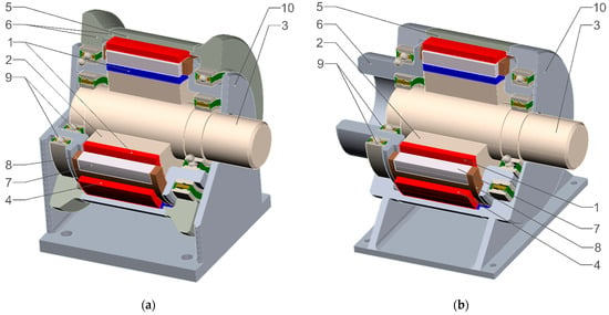
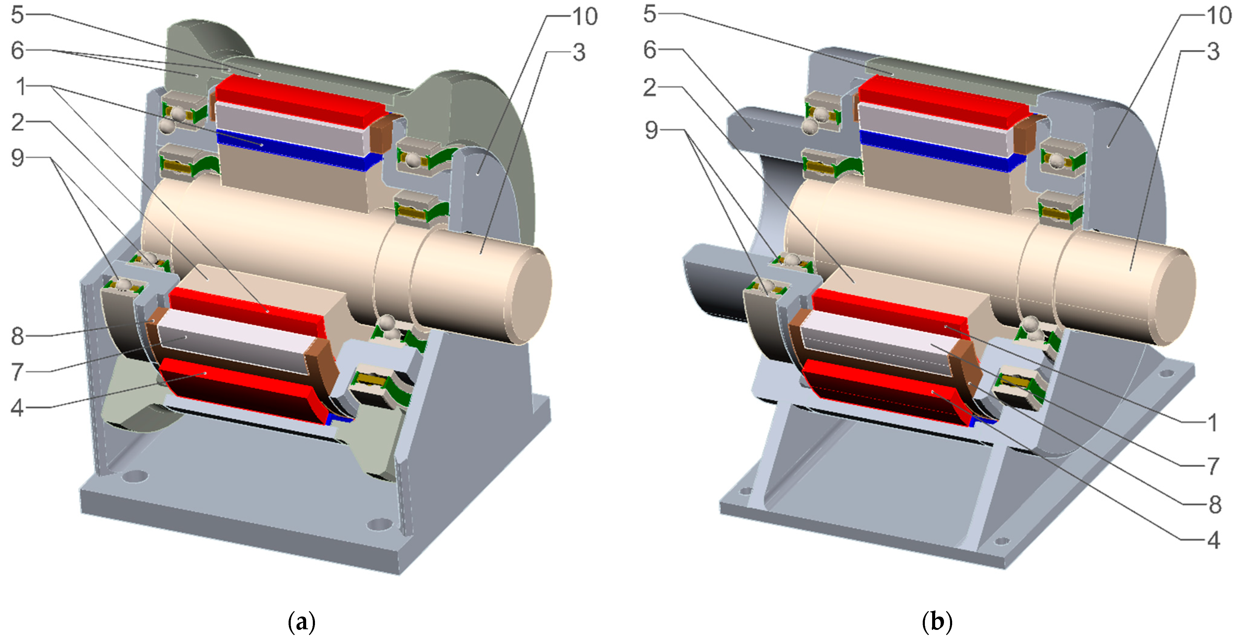
A coaxial magnetic gear consists of three basic parts: a high-speed rotor, a modulator, and a low-speed rotor. These rotors constitute magnetic-field inductors with a typical salient-pole structure and surface-mounted poles made of permanent magnets. Poles 1 and 4 are radially magnetized and are located on the cylindrical surfaces of the magnetic cores 2 and 5, on the outer surface of the high-speed rotor and on the inner surface of the low-speed rotor (Figure 1). The number of pole pairs of the high-speed and low-speed inductors will be denoted by ph and pl, respectively.
Figure 1.
Structure of the coaxial magnetic gear, (a) with a moving low-speed rotor; (b) with a moving modulator; 1—high-speed inductor poles, 2—high-speed inductor core, 3—high-speed shaft, 4—low-speed inductor poles, 5—low-speed inductor core, 6—low-speed shaft, 7—modulator sector, 8—modulator frame, 9—bearings, 10—housing.
The modulator has the form of a hollow cylinder whose wall consists of ferromagnetic sectors 7 and non-magnetic sectors 8 arranged alternately in the tangential direction. The number of flux-conducting segments of the modulator will be denoted by ms. The non-magnetic sectors usually also perform a supporting function and connect all structural elements of the modulator into a single unit.
This follows from the fact that the flux-conducting sectors are usually made as laminated stacks. Such a design limits power losses associated with eddy currents and remagnetization.
The magnetic field of the high-speed inductor, passing through a modulator with periodically varying tangential magnetic permeance, in addition to its fundamental harmonic of pole pair number 2ph, generates a higher-order harmonic of order ms/ph, where ms = ph + pl. This field, modulated owing to the magnetic inhomogeneity of the modulator, interacts with the field of the low-speed inductor of pole pair number 2pl and produces electromagnetic torque.
When the high-speed inductor rotates, the higher harmonic of its field begins to rotate in the direction opposite to that of the fundamental harmonic, with a frequency that differs from the rotational speed of the high-speed shaft by a factor of ph/pl. This harmonic interacts with the field of the low-speed rotor, causing it to rotate in the same direction and with the same frequency. As a result, the torque applied to the input shaft is transmitted to the output shaft and transformed in the ratio pl/ph. Therefore, the gear ratio of such a transmission is
The fundamental difference between the CMG design variants shown in Figure 1a,b lies in the selection of the moving component and, accordingly, in the method of mechanical power take-off. In design variant (a), the low-speed rotor rotates and serves as the output element of the gear, whereas the modulator remains stationary. In variant (b), by contrast, the low-speed inductor is stationary and forms part of the housing, while rotational motion is performed by the modulator, which acts as the output shaft. This change in the kinematic arrangement does not affect the magnetic interaction mechanism; however, it leads to differences in structural implementation, the transmission ratio, and operational properties, particularly with respect to ease of integration with the corresponding drive systems.
The transmission ratio in this case (Figure 1b) is determined as follows:
In the following, the CMG design with the low-speed rotor located on the outside (Figure 1a) will be analyzed. All results and conclusions obtained may, if necessary, also be generalized to the design shown in Figure 1b.
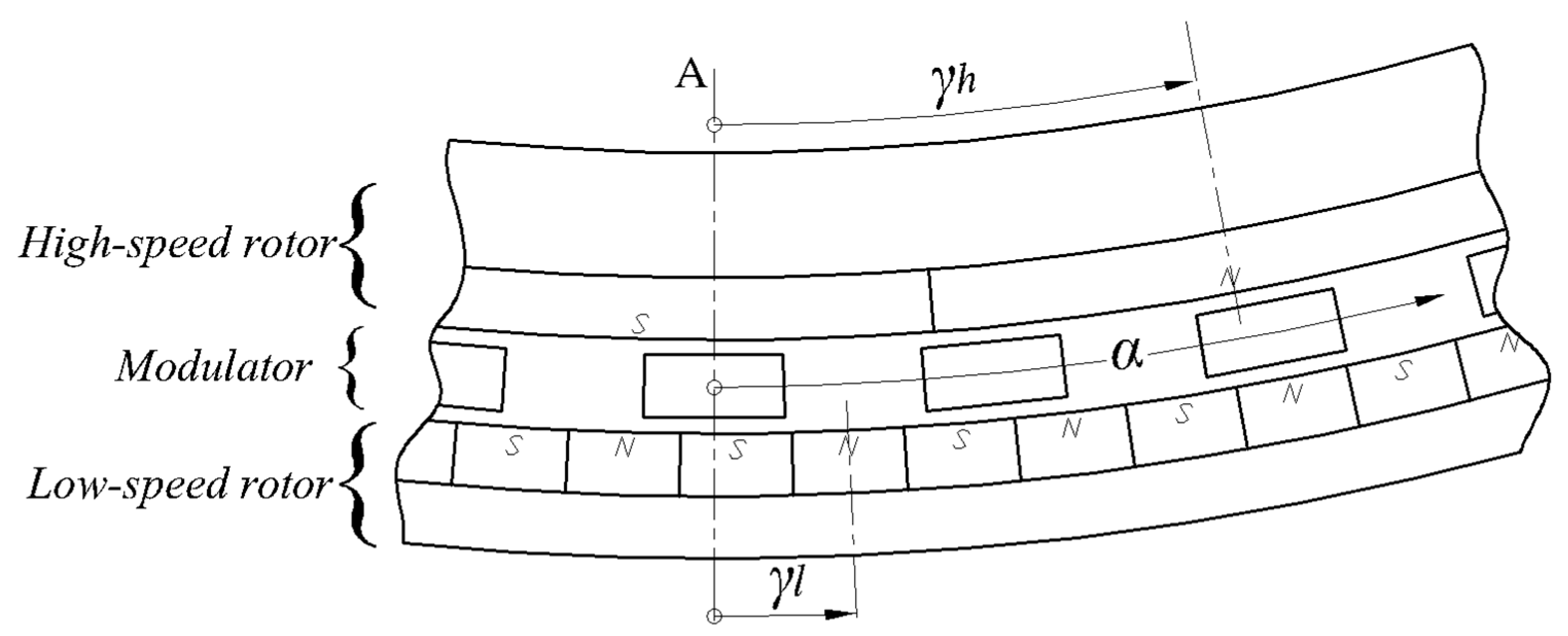
Let us assume that the magnetomotive forces (MMFs) of both rotors are distributed along the α coordinate according to a harmonic law (Figure 2). For their mathematical description, consider a coordinate system whose origin lies on the stationary axis A, directed radially and coinciding with the radial axis of symmetry of one of the ferromagnetic sectors of the modulator. The position of the high-speed rotor is determined by angle between axis A and the longitudinal axis of the pole rotating with angular velocity ωh. Angle describes the position of the low-speed rotor rotating with angular velocity ωl. In this case, the angular distribution of the rotor MMFs as a function of time can be written as
where α—the angular coordinate in the adopted coordinate system, rad;
, —the initial angular displacements of the CMG rotors, rad;
—the amplitudes of the magnetomotive forces of these rotors, A.
Figure 2.
Coordinate system of the magnetic gear.
Let us also assume that the magnetic permeance of the modulator together with the two air gaps is distributed in the tangential direction according to the following relationship:
where —the constant component of the magnetic permeance, H;
—the amplitude of the periodic component of this permeance, H.
The magnetic flux passing through one modulator pitch can be written as
where is the radial component of the magnetic flux density, T.
The average magnetic torque will be defined as the derivative of the magnetic-field energy with respect to the angular coordinate [3], Nm:
After mathematical transformations, taking into account (1), (3), and (4), the torque acting on the high-speed rotor is given by
whereas the torque acting on the low-speed rotor is given by
Analysis of expressions (7) and (8) shows that the maximum values of the magnetic torques of both rotors occur at an angular displacement of 90° between the pole axes, when the corresponding condition is . In what follows, this quantity will be referred to as the run-out angle.
Under steady-state conditions, the corresponding factor is ; therefore, the amplitude values of the magnetic torques may be determined as
Ultimately, the problem of determining the maximum magnetic torques of a CMG reduces to determining the amplitudes of the rotor MMFs and the periodic component of the equivalent magnetic permeance of the modulator.
3. Synthesis of the CMG Equivalent Circuit on the Basis of Magnetic-Field Analysis
To determine the quantities appearing in (9), an approach was used in which the magnetic field of the CMG is approximated by a certain branched magnetic circuit. This circuit is represented by an equivalent diagram. Solving the system of algebraic equations (SAE) describing this equivalent circuit makes it possible to determine the sought quantities.
The synthesis of such an equivalent circuit was carried out on the basis of an analysis of the CMG magnetic field obtained as a result of FEM analysis using ANSYS Multiphysics 16.2 software and the APDL programming language (Ansys Parametric Design Language).
The magnetic field was calculated for a digital prototype of the CMG whose dimensions and magnetic properties of the materials are given in Table 1. The relative positions of the rotors and the modulator corresponded to the configuration in which the maximum magnetic torques are produced.
Table 1.
Parameters, dimensions, and magnetic properties of CMG materials.
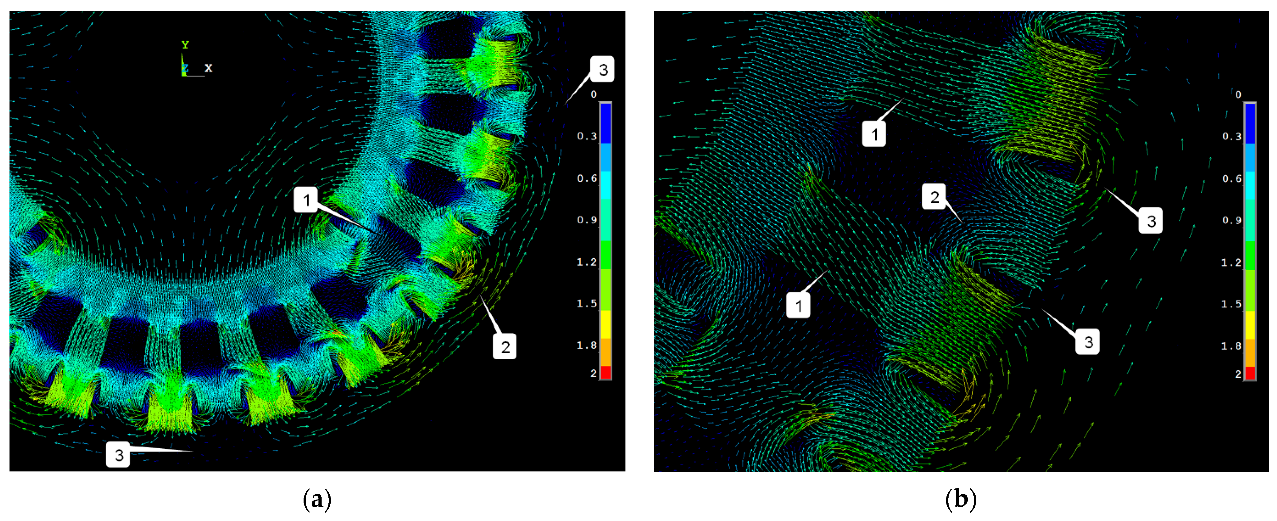
The magnetic-field analysis made it possible to conclude that:
- the magnetic flux of a high-speed rotor pole within the corresponding pole pitch is distributed almost uniformly among the ferromagnetic sectors of the modulator (Figure 3a);
- in the zones of lateral pole overlap (item 1 in Figure 3a), leakage flux is produced that partially closes in the tangential direction through the two nearest ferromagnetic sectors of the modulator and does not reach the outer air gap;
- the flux in the yoke of the high-speed rotor exhibits slight pulsations during rotation due to the influence of the field of the low-speed rotor inductor.
Figure 3.
Magnetic-flux-density vector field for one pole pair of the CMG: (a) high-speed rotor; (b) low-speed rotor.
It can be seen that the forward flux of the low-speed rotor pole whose axis approximately coincides with the axis of a ferromagnetic sector of the modulator (item 1 in Figure 3b) passes through the outer air gap practically without leakage and entirely reaches the inner air gap. There it becomes part of the total CMG flux closing through the yoke of the high-speed rotor. By contrast, the backward flux of the pole located approximately opposite a non-magnetic sector of the modulator closes via leakage paths to the two neighboring poles of opposite polarity (item 2 in Figure 3b).
Moreover, it is evident that the flux in the yoke of the low-speed rotor consists of the flux closing between two neighboring poles (item 2 in Figure 3a) and of the flux of pole pair number 2ph originating from the high-speed rotor (item 3 in Figure 3a). At locations where these components have the same direction, the yoke flux is strengthened, whereas in regions where their directions are opposite it is weakened (item 3 in Figure 3b). This phenomenon will be taken into account by an appropriate modification of the magnetic permeance values of the low-speed rotor yoke.
The analysis performed made it possible to determine the most probable paths of magnetic-flux flow and to synthesize the equivalent circuit of the branched magnetic circuit of the CMG (Figure 4) under the following assumptions:
- the magnetic field in the inner air gap is periodic, and for any pair of points separated by one pole pitch it differs only in sign;
- all sections of the magnetic circuit are replaced by lumped, linear magnetic permeances;
- losses in the ferromagnetic material are neglected.
Figure 4.
Equivalent magnetic-circuit diagram of the CMG.
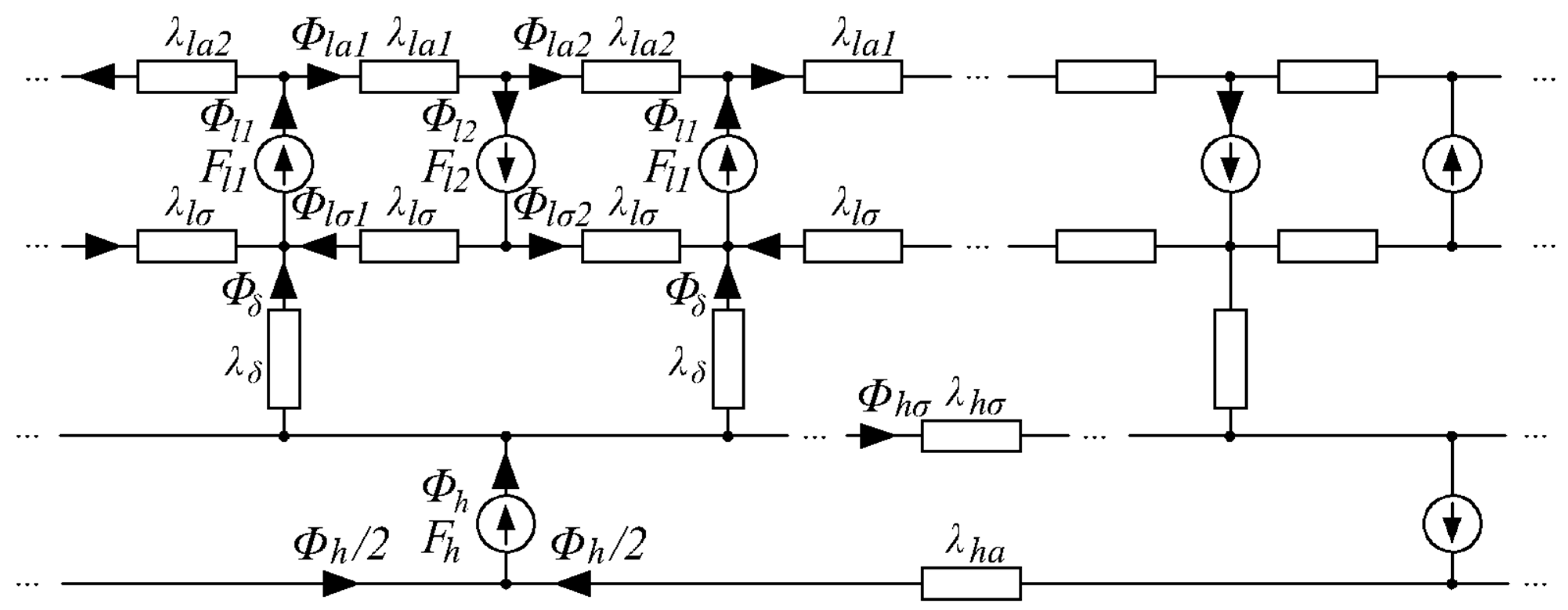
The following magnetic fluxes are indicated in Figure 4:
, , —the fluxes of the high-speed rotor pole and the fluxes of the low-speed rotor poles with, respectively, the same and the opposite magnetization directions;
, —the leakage fluxes of the low-speed rotor in the direction reinforced by the field of the high-speed rotor and in the opposite direction, respectively;
, —the fluxes in the yoke of the low-speed rotor in the direction reinforced by the field of the high-speed rotor and in the opposite direction, respectively;
—the leakage flux of the high-speed rotor;
—the flux flowing radially through both air gaps (inner and outer) and through a ferromagnetic sector of the modulator.
The magnetic characteristics of the individual sections of the CMG magnetic circuit, expressed as relationships between the MMF amplitudes of the high-speed and low-speed rotors and the corresponding magnetic fluxes, are described by
where
—the coefficients of the demagnetization line of the PM poles of the CMG;
, —the radial thicknesses of the high-speed and low-speed rotor poles, respectively;
, —the areas of the neutral cross-sections of the high-speed and low-speed rotor poles, respectively;
, —the remanent flux density and the coercive force, respectively, of the magnetically hard material from which the poles of the CMG rotors are made.
Resultant magnetic potential difference of the air gaps:
where
—the resultant magnetic permeance of the inner air gap, the ferromagnetic sector of the modulator, and the outer air gap;
—the coefficient accounting for the leakage of magnetic flux in the spaces between the ferromagnetic sectors of the modulator (its value was determined from an analysis of the accumulated calculation results and lies within the range 0.78–0.95).
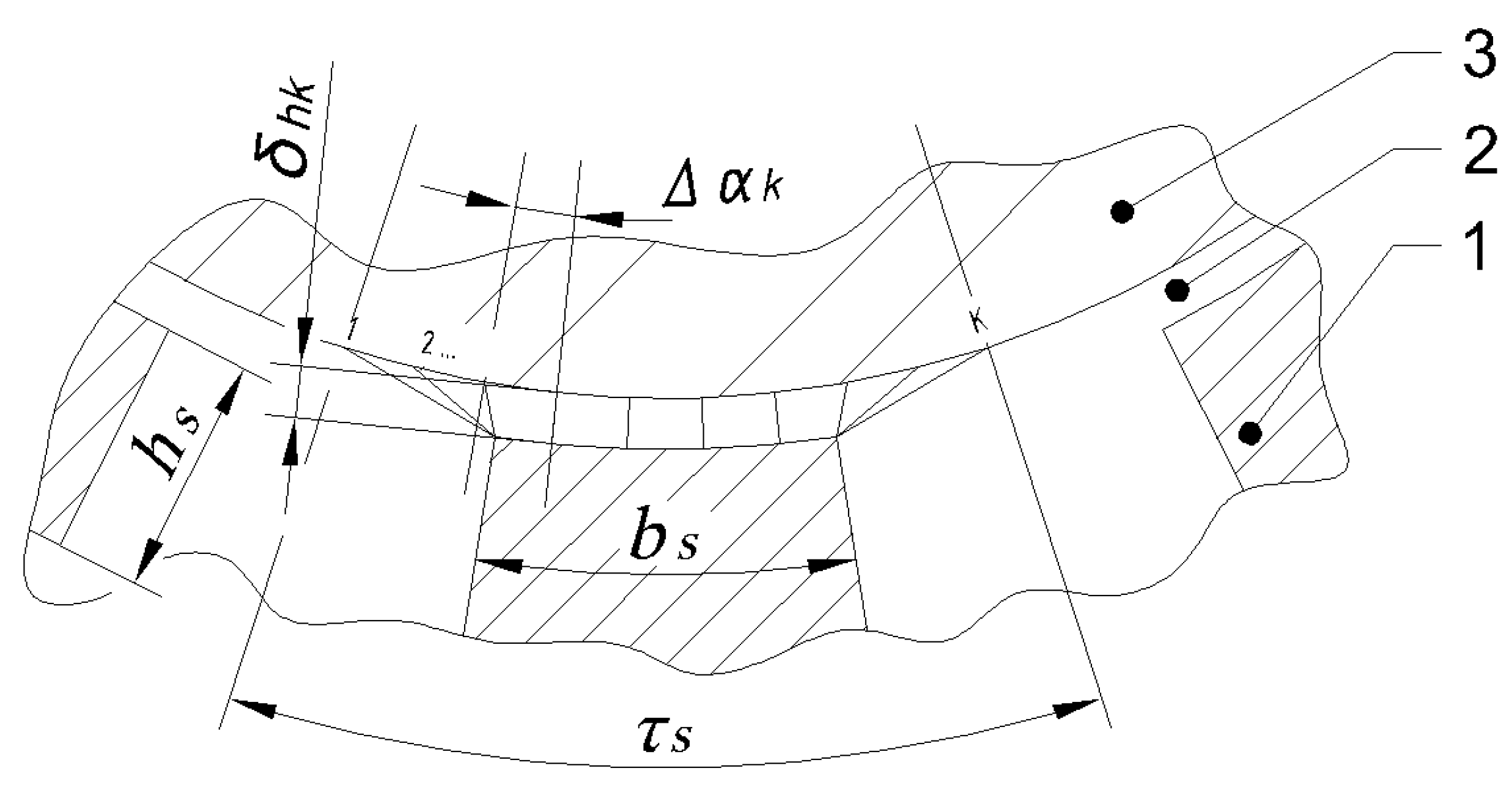
To determine the magnetic permeances of the inner and outer air gaps within one modulator pitch , the corresponding regions were divided into K flux tubes, in the general case of different widths (Figure 5). The resultant magnetic permeance of these gaps was determined as the sum of the permeances of the individual field flux tubes
where
—the absolute magnetic permeability of vacuum;
, —the outer diameter of the high-speed rotor and the inner diameter of the low-speed rotor, respectively;
—the angular width of the i-th flux tube ;
, —the lengths of the flux tubes in the inner and outer gaps, respectively ;
—the length of the air gaps.
Figure 5.
For calculating the magnetic permeance of the inner air gap; 1—ferromagnetic sector of the modulator; 2—air gap; 3—high-speed rotor pole.
The magnetic permeance of the modulator sector in the radial direction was determined from
where
—the relative magnetic permeability of the material of the ferromagnetic sectors of the modulator;
, —the average width and height of the ferromagnetic sector of the modulator, respectively (Figure 5).
Magnetic potential difference of the high-speed rotor yoke:
where
—the magnetic permeance of the high-speed rotor yoke (—the yoke thickness).
The magnetic potential differences of the low-speed rotor yoke on the sides of the fluxes with the same and opposite directions (item 3 in Figure 3a) were determined, respectively, by
where
—the corresponding magnetic permeances of the low-speed rotor yoke (—the yoke thickness). The coefficient accounts for the difference between the fluxes in the yoke between poles of opposite polarity depending on the direction of the additional flux of pole pair number .
Magnetic potential difference of the leakage flux of the high-speed rotor poles:
Magnetic potential differences of the leakage fluxes of the low-speed rotor poles:
where —the leakage permeance of the low-speed rotor pole located opposite a non-magnetic sector of the modulator. To determine it, the relevant region within the pole pitch was replaced by a system of flux tubes and the permeance value was calculated analogously to (14).
The equations describing the equivalent circuit shown in Figure 4, formulated on the basis law of total current,
and on the basis of the magnetic-flux continuity principle
The system of Equations (22) and (23) consists of nine linear equations and contains nine unknown fluxes , , , , , , , , . Solving it makes it possible to determine the MMF amplitudes required to calculate the magnetic torques according to (9)
The amplitude of the periodic component of the resultant magnetic permeance is determined as
where is a dimensionless parameter characterizing the gear shape factor. Its value was established empirically on the basis of an analysis of calculation results for CMG variants with different sets of principal dimensions and gear ratios. At present its value lies within the range 25 ÷ 35.
To verify this methodology, a comparison was made between the maximum values of the magnetic torques calculated using method (9), (22)–(25) and the values obtained from finite-element magnetic-field calculations. The comparison results are summarized in Table 2.
Table 2.
Comparative results for calculating maximum magnetic torques.
The comparative analysis indicates that the proposed methodology for determining the maximum magnetic torques of a CMG on the basis of an equivalent magnetic-circuit model is characterized by straightforward algorithmic implementation and provides torque estimates with an error of approximately 10–15% relative to numerical methods based on magnetic-field calculations. This level of accuracy results from the simplifications adopted in the description of the gear magnetic system. At the same time, the methodology does not require the use of specialized software and enables the rapid determination of the basic CMG design parameters, as well as the preparation of input data, including geometric dimensions and magnetic parameters, for further, more detailed modelling.
4. Mathematical Model of the Magnetic Gear
The need to develop a mathematical model of the CMG for calculating magneto-mechanical transients follows from the need for an adequate assessment of the dynamic behavior of this engineering object. Rapid changes in the operating mode of the gear—sudden load increases, changes in rotational speed, reversal of the rotation direction, overloads—affect the level of static and dynamic stability of the electromechanical systems incorporating CMGs. It is obvious that such effects should already be taken into account at the CMG design stage.
4.1. Mathematical Formulation of the Problem
Mechanical equilibrium equations of the high-speed and low-speed rotors
where
, —the moments of inertia of the rotating parts;
, —the driving torque of the high-speed shaft and the load torque of the low-speed shaft. When power is transmitted from the low-speed shaft to the high-speed shaft, becomes the driving torque and —becomes the load torque.
These torques act as excitations in the dynamic system under consideration. The driving torque of the high-speed shaft was described by
where , —respectively, the maximum torque on the input shaft () and the no-load angular speed ().
The load torque was described by the function
where
—the steady-state value of the load torque on the output shaft of the CMG;
—the angular speed above which the load torque assumes a constant value.
The system of Equations (26)–(28) was supplemented by the magneto-mechanical characteristic (MMC) [24] of the gear in the form of two functions:
determined on the basis of two-dimensional magnetic-field calculations.
The calculation of the magnetic torques in (29) was carried out using the so-called Maxwell stress tensor. According to this method, the force acting on any volume bounded by the outer surface S, can be determined by summing the elementary forces applied to the elements of that surface.
In the two-dimensional case, the force is determined by means of the so-called magnetic stresses acting on elementary segments with outward normal vector
where
—the Maxwell stress tensor for an isotropic medium;
—the components of the magnetic-flux-density vector outside the segment ;
—the normal vector to the segment .
On the basis of relationship (30), after transformation, the magnetic torque acting, for example, on one of the CMG rotors can be determined as
where
—the unit vector along the axis of rotation;
—the radial vector whose endpoint belongs to the cylindrical surface of the rotor tangent to the corresponding air gap.
The system of Equations (26)–(29) contains six scalar equations and six unknowns: γh, γl, ωh, ωl and Mh, Ml. It constitutes the mathematical formulation of the problem of calculating magneto-mechanical transients in a CMG.
This system is nonlinear owing to the nonlinear relationships (29). Supplementing it with the initial condition
we get a Cauchy problem.
4.2. Solution Algorithm
The implicit Euler method was used to integrate Equations (26)–(29).
After algebraization of the derivatives at the k-th integration step, a nonlinear system of algebraic equations SAE is obtained, which was solved by Newton’s method. The residual vector of the nonlinear system SAE, calculated from the (n − 1)-th approximation of the root, has the form
The coefficient matrix of the linear system SAE generated from the nonlinear system at the k-th integration step, written with respect to the corrections of the unknown angles , in the n-th Newton iteration, has the form
where
—the derivatives of the MMCh (29), calculated on the basis of the (n − 1)-th approximation of the unknowns and . They are determined using invariant function approximation directly from the results of CMG magnetic-field calculations [25];
—the derivatives of (27) and (28), calculated from the (n − 1)-th approximation of the root.
We form the vector of corrections to the CMG rotor angular positions in the n-th Newton iteration
Then, the linear system SAE to be solved in the n-th Newton iteration takes the form
Thus, to perform the k-th integration step, the following operations should be carried out:
- Compute the residual values (33) from the (n − 1)-th approximation of the root.
- Compute the values of the differential parameters , (36) and the magneto-mechanical parameters , , , (35) from the (n − 1)-th approximation of the root.
- Compute the elements of the coefficient matrix (34).
- Solve system SAE (38) with respect to the unknown corrections
- Compute the n-th approximation of the unknowns according to
- Compute the remaining unknowns according to
If the accuracy of the determined corrections is insufficient, repeat items 1–6. Otherwise, proceed to the next integration step.
This algorithm was implemented in the form of a computer program written in APDL.
4.3. Mathematical Experiments
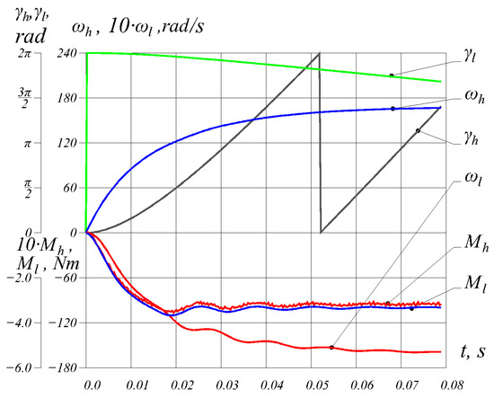
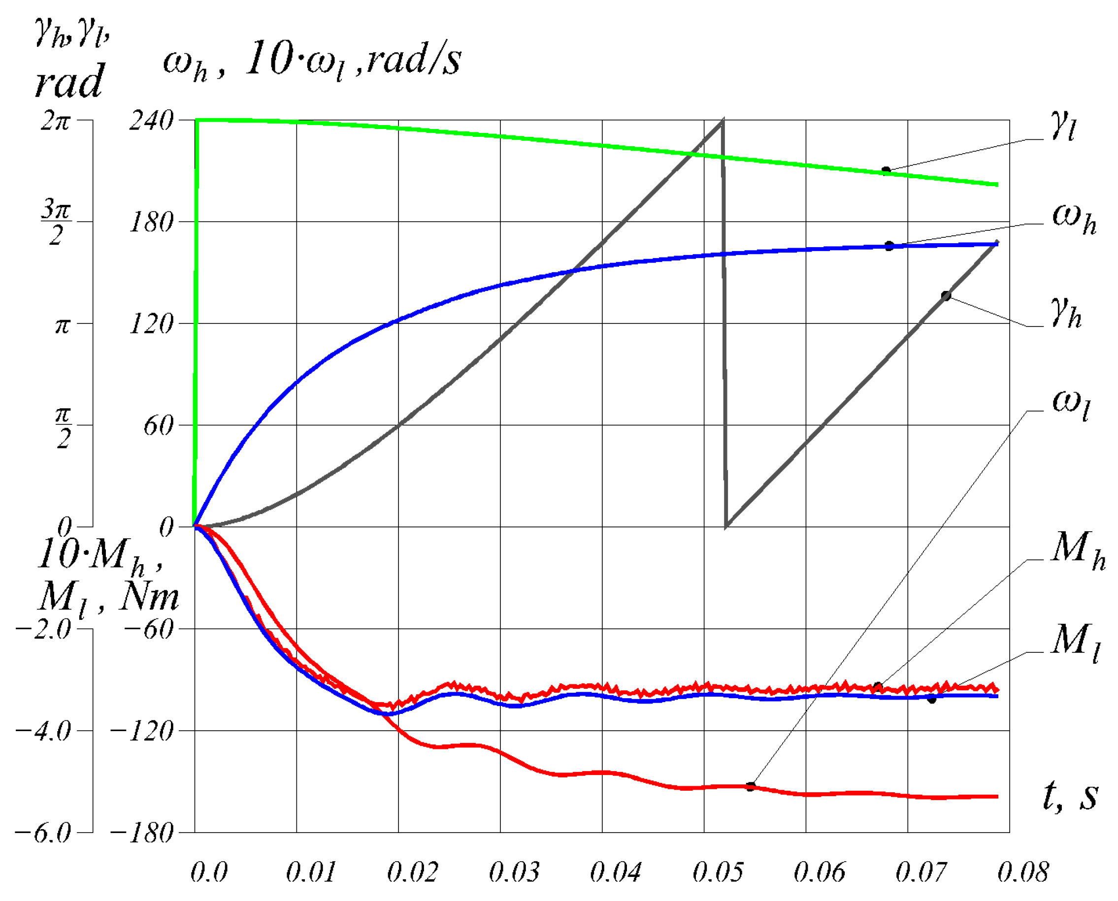
The performance of model (26)–(29) was tested on a benchmark problem using the input data from Table 1. The CMG start-up process was investigated. Torque (27) was applied to the input shaft as a function of rotational speed Mhs = −7.71 × 10⁻³ ωh + 1.615, [N·m]. The steady-state value of load torque (28) on the output shaft was Mls = 3.306 N·m. The rotor moments of inertia were Jh = 1.289 × 10⁻⁴ kg·m2 and Jl = 6.152 × 10⁻⁴ kg·m2. The simulation results are shown in Figure 6.
Figure 6.
Time dependences of rotor angular positions, rotational speed, and magnetic torques of the high-speed and low-speed rotors.
It is evident that, under transient conditions, the CMG behaves like a two-mass oscillatory system whose time constants are determined by the moments of inertia of the rotating parts. Pulsations of the magnetic torque are also observed at a frequency corresponding to the influence of the cogging torque. Complete elimination of this influence is impossible; however, to minimize it, the concept of the cogging factor [2] was used
where —the least common multiple of 2pl and ms. The parameters of the CMG in Table 1 ensure the minimum value of this coefficient CT = 2·21·23/966 = 1.
Analysis of expression (41) shows that the minimum value of the cogging torque is ensured by fractional gear-ratio values.
The transient response shown in Figure 6, obtained computationally, does not contradict the physics of the phenomena occurring in the CMG during start-up, and its quantitative analysis confirms the correctness and functionality of the proposed computational algorithm (33)–(40).
5. Optimization Search for the Principal Dimensions
One possible reason for the limited implementation of magnetic gears in general engineering practice is the lack of established guidelines and recommendations for their design. Usually, such recommendations include relationships between the principal dimensions defining the designed object and a number of technical requirements, e.g., power, rotational speed, loads of various origins, etc. In the case of a CMG, we propose to regard the standardized shaft center height h (according to IEC 60072-1), the axial length of the magnetic core , and the key requirement—the value of the linear density of the maximum torque on the output shaft (corresponding to a 90° run-out angle) . We also assume that the rotation-axis height is related to the outer diameter of the output shaft (low-speed rotor) by the relationship .
To establish a deterministic relationship between the value of ML and the principal dimensions or any other indicators, it is necessary to select, from the entire set of design parameters, only those that provide the maximum possible value of ML under the dimensional constraint h and at fixed magnetic properties of the material from which the rotor poles will be made. To solve this problem, an optimization search based on the gradient method was used.
Compared with, for example, random-search or exhaustive-search methods, the gradient method is characterized by high computational efficiency. It is simple to implement and performs well in high-dimensional problems. Unlike stochastic or heuristic methods, gradient algorithms are deterministic and are easier to analyze and verify.
The objective function F was taken as the dependence of ML on four optimization criteria: the yoke thickness of the low-speed rotor , the radial thicknesses of the poles of the high-speed and low-speed rotors , and the thickness of the magnetic sector of the modulator in the radial direction,
The outer diameter of the low-speed rotor was treated as constant . The angular fill factor of the modulator pitch by the magnetic sector (Figure 5) and the pole embrace coefficients of both rotors .
Let us combine all optimization criteria into a column vector of independent design variables
The value of vector , that ensures the minimum value of objective function (42) is determined by an iterative procedure. The approximation of vector at the k-th iteration can be written as
where —(k − 1)-th approximation of the independent-variable vector;
ζ—a constant coefficient ensuring convergence of the iterative procedure (in our case ζ = 0.5 ÷ 1.5);
—the column of partial derivatives of function F with respect to the independent variables.
When the difference between the next and previous approximations of the independent-variable vector becomes smaller than a previously specified accuracy, the iterative procedure is terminated and the set of criteria is taken to be optimal for the given set of design parameters and constraints (h, ph, ms, pl, etc.).
To determine the elements of column (45), interpolation theory was used. It was assumed that function F can be approximated by a second-order Taylor polynomial with four independent variables:
where —the Taylor row;
—the column of coefficients.
To determine these coefficients, a vector of function F values corresponding to a set of 15 different vectors of independent variables was formed. These vectors were distributed in the four-dimensional space of the independent variables so as to satisfy the previously established constraints and avoid geometric collisions. In particular, one of the conditions imposed on each vector in the set was
Note that the elements of vector were computed using the procedures of the model described in the previous section, namely its MMCs (29).
After populating vector , with values, the column of coefficients was determined as the solution of the equation
where —the Taylor matrix composed of Taylor rows calculated for the corresponding sets of vectors .
Formally, solution (48) can be written as
Then the expression for the interpolant of function F takes the form
and the partial derivative (50) with respect to any of the independent variables (43) is determined as
where —any element of vector (43) ;
is the differentiation matrix of the Taylor row with respect to the j-th element of vector (43). The size of this matrix is 15 × 15. For example, to compute the derivative , the matrix takes the form
Taking (51) into account, the column of partial derivatives is
where —a block-diagonal matrix of size 4 × 45;
—a block-diagonal matrix of size 45 × 45;
—a block-diagonal matrix of size 45 × 45;
—a column vector of size 45.
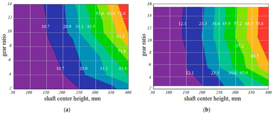
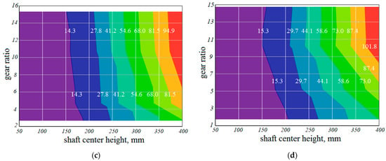
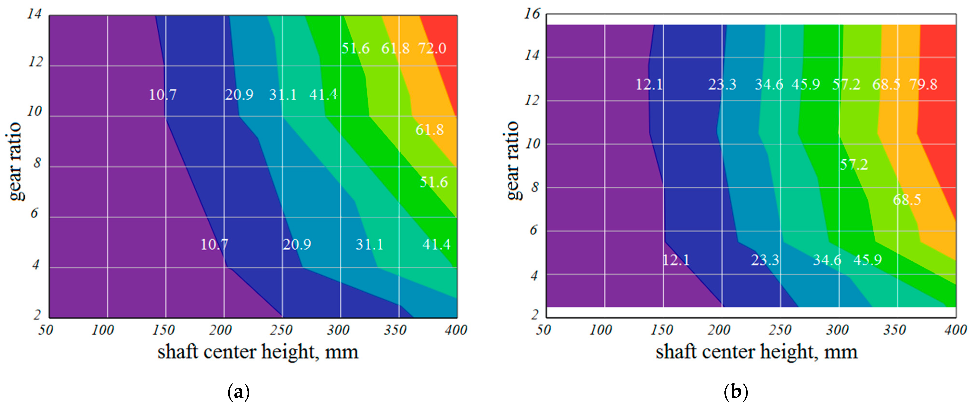
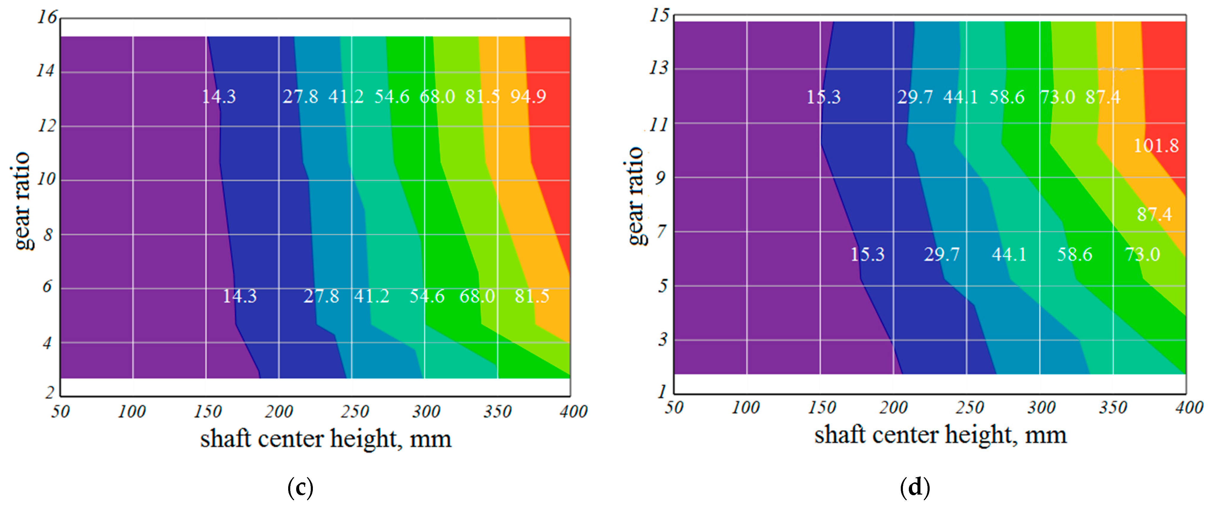
On the basis of the results of optimization calculations (42)–(53), relationships for the linear torque density ML were constructed for a series of CMGs with shaft center height in the range 56 ≤ h ≤ 400 mm, number of pole pairs of the high-speed rotor in the range 1 ≤ ph ≤ 4, and gear ratio in the range 1.8 ≤ kr ≤ 15.5. The distribution of this function in the h-kr coordinate plane for four values of ph is shown in Figure 7.
Figure 7.
Distribution of the linear density of the maximum torque [kN·m/m] as a function of shaft center height h and gear ratio kr for: (a) ph = 1; (b) ph = 2; (c) ph = 3; (d) ph = 4.
On the basis of the established values of shaft center height h, gear ratio kr, overload capability coefficient km and linear torque density ML determined from the graphs in Figure 7, the obtained relationships make it possible, among other things, to determine the active length of the CMG .
It should be noted that all sets of values pl, ms and ph, involved in the optimization calculations (42)–(53) ensured the minimum possible value of the cogging factor (41), i.e., CT = 1. However, this does not always mean that the amplitude of magnetic-torque ripple is acceptable from the viewpoint of the technical requirements of a particular CMG application. It was observed that variants with ph = 1 are characterized by an increased level of torque ripple—it may reach about ±50% of the torque on the high-speed shaft and about ±25% on the low-speed shaft.
Attention should also be paid to another feature of the magnetic-gear design process—the technological feasibility of manufacturing CMGs with high gear ratios. For example, the variant ph = 4, kr = 14.8 for h = 56 mm would require mounting poles of dimensions approximately 0.5 mm × 1.5 mm on a diameter of about 104 mm, which considerably complicates the manufacturing of the low-speed rotor of such a gear.
We hope that the developed relationships (Figure 7), recommendations, and comprehensive analysis of the individual factors affecting CMG operation will be helpful in selecting an appropriate structure already at the preliminary design decision stage.
6. Physical Experiments
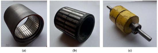
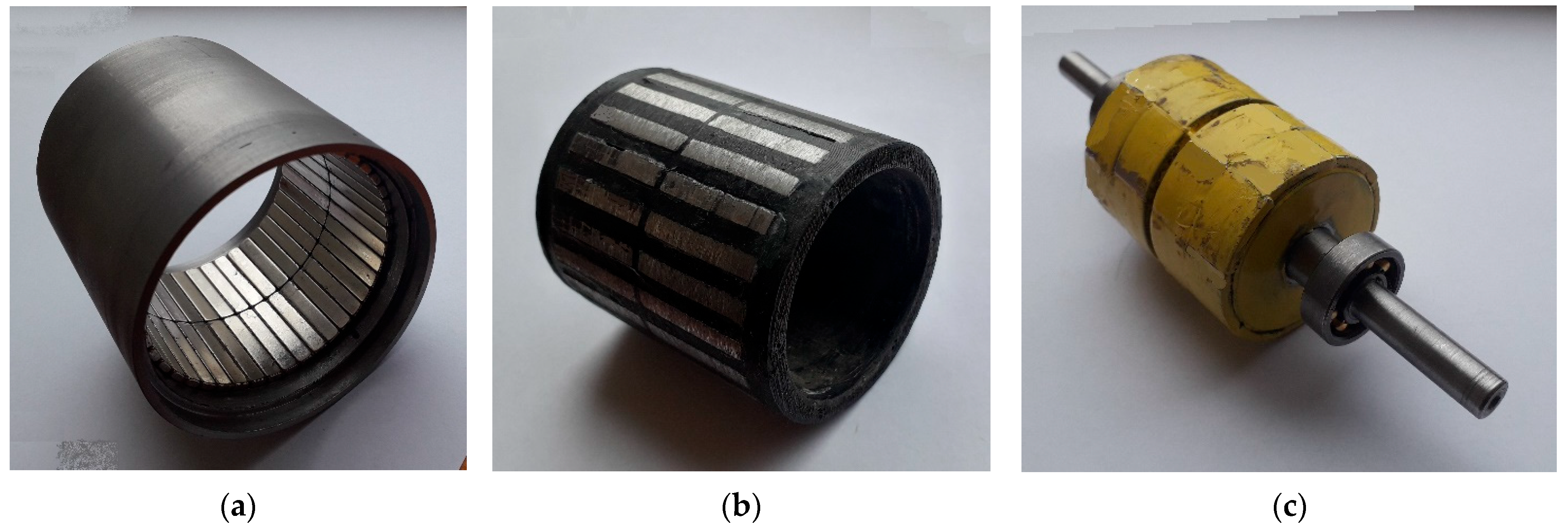
The aim of the experimental study is to verify the mathematical model (26)–(29) intended for calculating magneto-mechanical transients in a CMG. For this purpose, a physical CMG prototype with the parameters and dimensions given in Table 1 was built. The cores of both rotors are made as solid components from structural steel. The modulator housing was manufactured by 3D printing from ABS plastic. To increase its mechanical stiffness, it was divided along the axis into two equal parts by means of a ring stiffener. The magnetic sectors of the modulator were made as laminations of isotropic electrical steel sheets 0.5 mm thick, coated on both sides with an insulating layer. The general arrangement of the prototype corresponds to the scheme in Figure 1a. The active-part components are shown in Figure 8.
Figure 8.
Components of the CMG ph/pl/ms = 2/21/23: (a) low-speed rotor; (b) modulator; (c) high-speed rotor.
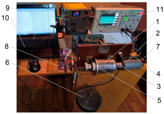
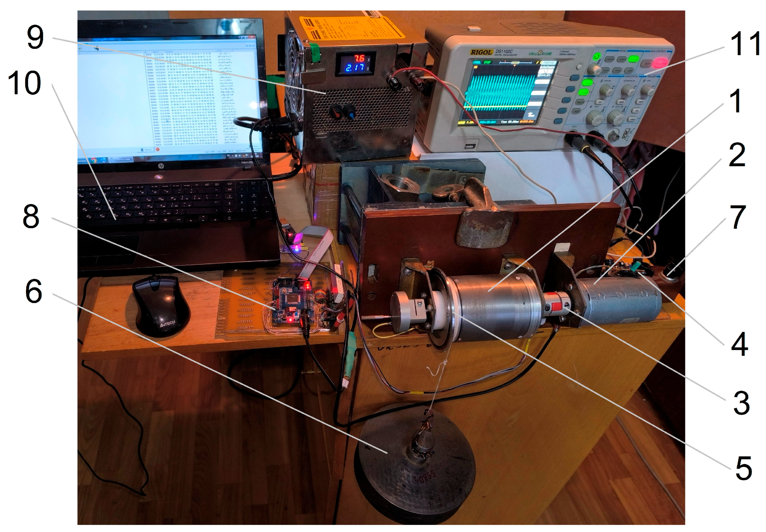
The test rig for the prototype consists of magnetic gear 1, driving motor 2, mechanical load 6, and measuring and control equipment (Figure 9). Encoders were mounted on both CMG shafts to record the current angular position of each rotor. The rotation angle of the high-speed shaft is determined by an absolute magnetic encoder (Austriamicrosystems AG AS5045, Premstätten, Austria) with a resolution of 12 bits. The rotation angle of the low-speed rotor shaft is recorded by an incremental encoder (Avago Technologies AEDR-8300-1W, San Jose, California, USA) with 2100 markers per full revolution.
Figure 9.
CMG test rig 1—coaxial magnetic gear; 2—driving motor; 3—coupling; 4—absolute magnetic encoder; 5—incremental optical encoder; 6—load; 7—shunt for motor-current measurement; 8—data acquisition and transmission system; 9—power supply; 10—computer; 11—oscilloscope.
Information from these encoders was read by a microprocessor-based data-processing system built around an 8-bit microcontroller (Atmel ATMega128, San Jose, California, USA) and transmitted to a computer for acquisition and further processing. A two-channel oscilloscope made it possible to record the current and voltage of the driving motor (Buehler a-c4713-60027-1, Bühler Motor GmbH, Zhuhai, China).
The rotational speeds of both shafts, nh and nl, were determined numerically by differentiating in time the angular-position functions γh(t) and γl(t), obtained directly from the encoders.
The torque on the high-speed shaft, Mhs, of the driving motor was calculated using the previously established analytical expression
as a function of rotational speed nh, supply voltage UDC, and current draw IDC.
Expression (54) is a second-order Taylor polynomial with three independent variables. Its coefficients were determined from the mathematical processing of experimental data obtained from direct loading tests of the driving motor for a series of different constant loads and supply voltages. The ten coefficients of polynomial (54) were found to be as follows:
Expression (54) is defined for the following ranges of the independent variables: nh = 130 ÷ 1400 rpm; UDC = 5 ÷ 22 V; IDC = 0.3 ÷ 8.0 A.
The torque on the low-speed shaft Mls was calculated according to
directly from the gravitational force of load 6 (Figure 9), , the radius of the driven pulley and the moment of inertia of the low-speed shaft.
Thus, the stand shown in Figure 9 makes it possible to record the time dependences of the angular positions of both rotors γh(t), γl(t), their rotational speeds ωh(t), ωl(t) and the torques on the corresponding shafts Mhs(t), Mls(t) on the basis of a physical experiment.
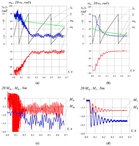
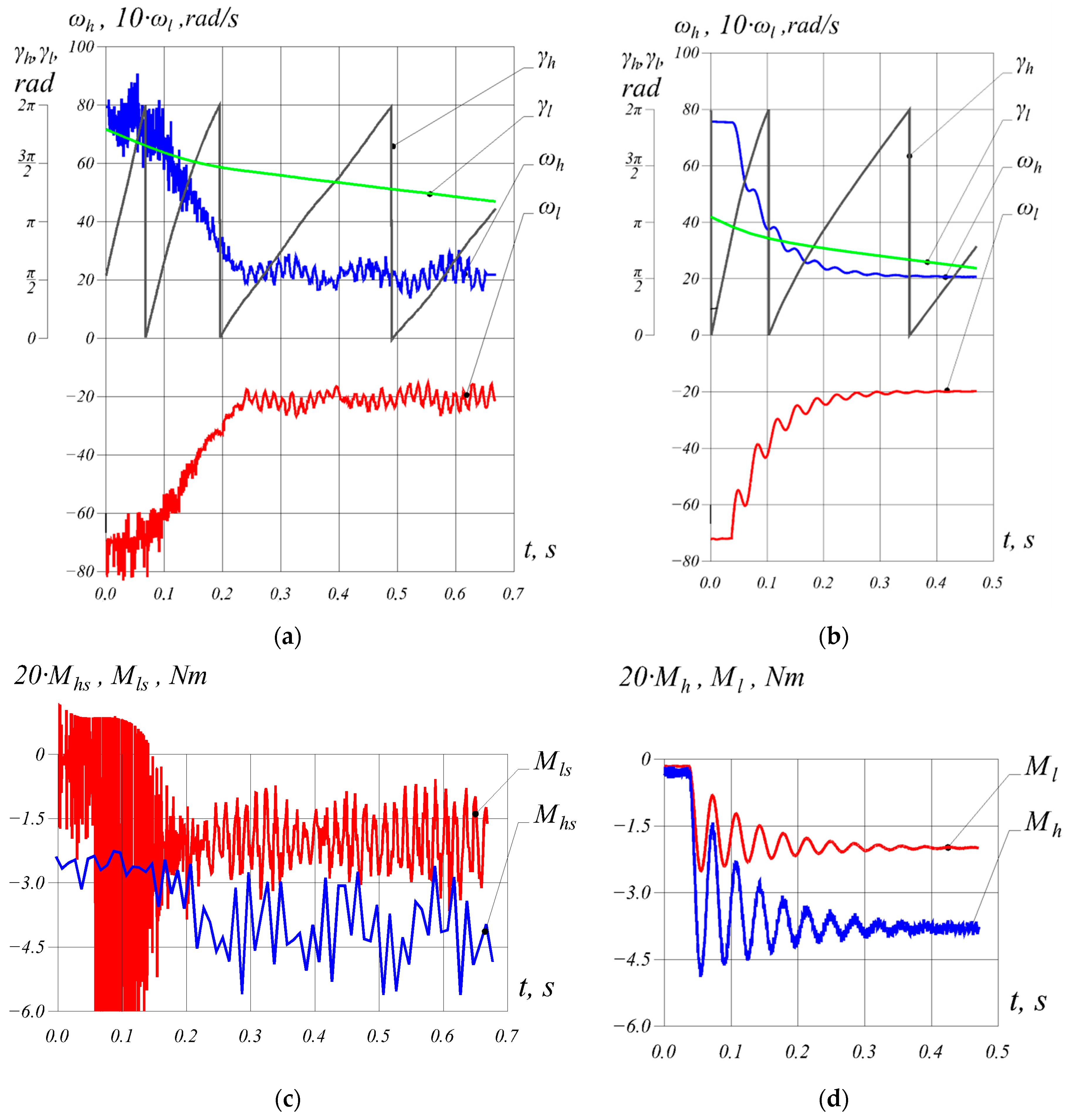
Figure 10a,c show such dependences corresponding to the process of a sudden increase in the load on the low-speed shaft of the CMG from 0.1538 N·m to 1.987 N·m. The steady-state average rotational speeds before the load increase were ωh/ωl = 75.59/7.148 rad/s, and after the increase they were 20.98/1.993 rad/s.
Figure 10.
Time dependences: (a,b)—rotor angular positions γh, γl and rotational speeds ωh, ωl; (c,d)—torques on shafts Mhs, Mls and magnetic torques Mh, Ml; (a,c)—obtained experimentally; (b,d)—obtained computationally.
These dependences show the oscillatory nature of CMG operation in both transient and steady states. The frequency spectrum of the torques, and consequently the rotational speeds, depends on the ratio of the principal dimensions and on the value of the gear load. Vibrations occur at two clearly distinguished frequencies. The lower one results from the natural frequencies of the mechanical system, whereas the higher one is due to the cogging torque. For the given system ph/pl/ms, the period of these vibrations for the high-speed rotor is 2·π/ms·kr ≈ 0.026 rad.
A significant influence on the amplitude of these vibrations is exerted by manufacturing inaccuracies of the CMG components, possible deformation of the modulator body under dynamic loads, and magnetic asymmetry of the inductors caused by nonuniform magnetic properties of individual poles.
Comparison of the shaft–torque dependences obtained experimentally (Figure 10c) and computationally (Figure 10d) showed a fairly significant difference in the amplitudes of torque pulsations on both shafts. This fact is explained by the specific nature of recording the rotor angular positions during the experiment. The largest error in the current values of the low-speed shaft angular position is introduced by the absolute magnetic encoder. According to the technical documentation of this device, in the worst case the spread of indications may reach ± 1.4°. Determination of torque Mls requires numerical evaluation of the second derivative of γl (56) which leads to the observed pulsations. The discrete nature of the indications of the incremental encoder used to register angle γh also causes pulsations in Mhs(t), because the rotational speed nh, entering expression (54) also requires differentiation of γh.
By contrast, the steady-state values of the electromagnetic torque under the increased load and the mechanical time constant practically coincide, which indicates an acceptable level of adequacy of the developed model.
A considerable discrepancy was also observed in the steady-state values of torque on the high-speed shaft at a low load on the low-speed shaft of 0.1538 N·m. Torque Mhs in this mode is 0.1340 N·m, while the calculated value of torque Mh = 0.01459 N·m. The difference between them is explained by energy losses in the physical CMG prototype, which are not taken into account in the mathematical model and are compensated by the power on the shaft of the driving motor. This makes it possible to estimate the sum of eddy-current and remagnetization losses in the gear core together with bearing-friction losses in this operating mode as (Mh − sMh)ωh ≈ 9.0 W.
7. Conclusions
A method for determining the maximum magnetic torques of a CMG on the basis of an equivalent magnetic-circuit model was developed, enabling an approximate assessment of the influence of geometric parameters and the magnetic properties of materials on the operational indicators of the gear. The error in determining the maximum torques does not exceed ±15%. A limitation of the method is the presence of an empirical coefficient dependent on the dimensional ratio, which requires further refinement. At the same time, the method is useful for assessing steady-state quantities at the preliminary design stage.
A mathematical model of CMG dynamics was developed using a quasi-steady two-dimensional approximation of the magnetic field. The model accounts for the geometry of the magnetic circuit, the spatial distribution of the magnetic vector potential, the mutual position of the rotors, the harmonic composition of the field, and magnetic saturation. The error in determining the torque on the low-speed shaft under steady-state conditions does not exceed 5.5% compared with the experimental results.
As a result of the optimization procedure, the dependence of the linear density of the maximum torque [N·m/m] on the outer diameter of the CMG, the number of pole pairs of the high-speed rotor, and the gear ratio was established, making it possible to take into account the influence of these parameters on the force-related characteristics of the transmission. It was found that an increase in the number of poles of the high-speed rotor is accompanied by an increase in linear torque density. In particular, for a CMG with a radial dimension of 56 mm, the linear torque density ranges from 11 to 15 N·m/m, whereas for 400 mm it ranges from 72 to 102 N·m/m.
The study showed that magnetic-torque pulsations are typical of CMG operation in every operating mode. At relatively low loads their amplitude increases, which can be explained by the nonlinear dependence of the run-out angle on the load. The manufacturing accuracy of CMG components and the mechanical stiffness of the structure significantly affect the value of these pulsations.
An analysis of the efficiency of this type of magnetic gear revealed the reason for the discrepancy between the experimentally obtained shaft torques and the calculated values, namely the omission of energy dissipation in the mathematical model (26)–(29). This indicates a promising direction for improving the adequacy of the model by including magnetic and mechanical losses. In addition, the need to reduce magnetic losses not only by laminating the modulator sectors but also by laminating the rotor cores, especially the low-speed rotor, was established.
Overall, despite all its advantages, the coaxial magnetic gear exhibits a number of limitations: significant pulsations of the rotational speed of the low-speed shaft under even minimal instability of the load torque; practical difficulty in predicting the position of the output shaft from the position of the input shaft; and low torsional stiffness of the gear, dependent on load, which prevents precise torque transmission.
Author Contributions
Conceptualization, O.M. and D.C.; methodology, O.M. and D.C.; software, O.M.; validation, O.M. and D.C.; formal analysis, O.M. and D.C.; investigation, O.M. and D.C.; resources, O.M.; data curation, O.M.; writing—original draft preparation, O.M. and D.C.; writing—review and editing, O.M. and D.C.; visualization, O.M.; supervision, D.C.; project administration, D.C.; funding acquisition, D.C. All authors have read and agreed to the published version of the manuscript.
Funding
This research received no external funding.
Informed Consent Statement
Informed consent was obtained from all subjects involved in the study.
Data Availability Statement
Data are contained within the article.
Conflicts of Interest
The authors declare no conflicts of interest.
References
- Ruiz-Ponce, G.; Arjona, M.A.; Hernandez, C.; Escarela-Perez, R. A Review of Magnetic Gear Technologies Used in Mechanical Power Transmission. Energies 2023, 16, 1721. [Google Scholar] [CrossRef] [Scilit]
- Wang, Y.; Filippini, M.; Bianchi, N.; Alotto, P. A review on magnetic gears: Topologies, computational models, and design aspects. IEEE Trans. Ind. Appl. 2019, 55, 4557–4566. [Google Scholar] [CrossRef] [Scilit]
- Aiso, K.; Akatsu, K.; Aoyama, Y. A novel reluctance magnetic gear for high-speed motor. IEEE Trans. Ind. Appl. 2019, 55, 2690–2699. [Google Scholar] [CrossRef] [Scilit]
- Gardner, M.C.; Johnson, M.; Toliyat, H.A. Analysis of high gear ratio capabilities for single-stage, series multistage, and compound differential coaxial magnetic gears. IEEE Trans. Energy Convers. 2019, 34, 665–672. [Google Scholar] [CrossRef] [Scilit]
- Rashidi, H.; Pishdad, D. Integrated multispeed magnetic gears: A novel approach to design of magnetic transmission systems. IEEE Trans. Magn. 2014, 51, 8700308. [Google Scholar] [CrossRef] [Scilit]
- Duan, G.; Gupta, T.; Sutton, E.; Wang, M.; Gardner, M.C.; Khan, S.A.; Praslicka, B. Cycloidal magnetic gear combining axial and radial topologies. IEEE Trans. Energy Convers. 2022, 37, 2130–2137. [Google Scholar] [CrossRef] [Scilit]
- Fu, W.N.; Li, L. Optimal design of magnetic gears with a general pattern of permanent magnet arrangement. IEEE Trans. Appl. Supercond. 2016, 26, 0606705. [Google Scholar] [CrossRef] [Scilit]
- Praslicka, B.; Gardner, M.C.; Johnson, M.; Toliyat, H.A. Review and analysis of coaxial magnetic gear pole pair count selection effects. IEEE J. Emerg. Sel. Top. Power Electron. 2021, 10, 1813–1822. [Google Scholar] [CrossRef] [Scilit]
- Mateev, V.; Marinova, I. Loss estimation of magnetic gears. Electr. Eng. 2020, 102, 387–399. [Google Scholar] [CrossRef] [Scilit]
- Tallerico, T.F.; Scheidler, J.J.; Cameron, Z.A. Electromagnetic mass and efficiency of magnetic gears for electrified aircraft. In Proceedings of the 2019 AIAA/IEEE Electric Aircraft Technologies Symposium (EATS), Indianapolis, IN, USA, 22–24 August 2019; pp. 1–25. [Google Scholar] [CrossRef] [Scilit]
- Gardner, M.C.; Praslicka, B.; Johnson, M.; Toliyat, H.A. Optimization of coaxial magnetic gear design and magnet material grade at different temperatures and gear ratios. IEEE Trans. Energy Convers. 2021, 36, 2493–2501. [Google Scholar] [CrossRef] [Scilit]
- Niu, S.; Chen, N.; Ho, S.L.; Fu, W.N. Design optimization of magnetic gears using mesh adjustable finite-element algorithm for improved torque. IEEE Trans. Magn. 2012, 48, 4156–4159. [Google Scholar] [CrossRef] [Scilit]
- Lee, J.I.; Shin, K.H.; Bang, T.K.; Ryu, D.W.; Kim, K.H.; Hong, K.; Choi, J.Y. Design and analysis of the coaxial magnetic gear considering the electromagnetic performance and mechanical stress. IEEE Trans. Appl. Supercond. 2020, 30, 3700105. [Google Scholar] [CrossRef] [Scilit]
- Desvaux, M.; Traullé, B.; Latimier, R.L.G.; Sire, S.; Multon, B.; Ahmed, H.B. Computation time analysis of the magnetic gear analytical model. IEEE Trans. Magn. 2017, 53, 7000409. [Google Scholar] [CrossRef] [Scilit]
- Zhang, X.; Liu, X.; Wang, C.; Chen, Z. Analysis and Design Optimization of a Coaxial Surface-Mounted Permanent-Magnet Magnetic Gear. Energies 2014, 7, 8535–8553. [Google Scholar] [CrossRef] [Scilit]
- Johnson, M.; Gardner, M.C.; Toliyat, H.A. A parameterized linear magnetic equivalent circuit for analysis and design of radial flux magnetic gears—Part I: Implementation. IEEE Trans. Energy Convers. 2017, 33, 784–791. [Google Scholar] [CrossRef] [Scilit]
- Wu, Y.C.; Jian, B.S. Magnetic field analysis of a coaxial magnetic gear mechanism by two-dimensional equivalent magnetic circuit network method and finite-element method. Appl. Math. Model. 2015, 39, 5746–5758. [Google Scholar] [CrossRef] [Scilit]
- Gerber, S.; Wang, R.J. Cogging torque definitions for magnetic gears and magnetically geared electrical machines. IEEE Trans. Magn. 2018, 54, 8103209. [Google Scholar] [CrossRef] [Scilit]
- Huang, Y.; Jing, L. Design and Optimization of a Double V-Shaped Coaxial Magnetic Gear with Hybrid PM Array. J. Electr. Eng. Technol. 2026, 21, 2677–2690. [Google Scholar] [CrossRef] [Scilit]
- Filippini, M.; Alotto, P. Coaxial magnetic gear design and optimization. IEEE Trans. Ind. Electron. 2017, 64, 9934–9942. [Google Scholar] [CrossRef] [Scilit]
- Akyerden, E.; Cansız, A. Magnetic Gear System Analysis with Bulk Superconductor Modelling on Rotor Sections via Pulsed Field Magnetization. J. Supercond. Nov. Magn. 2026, 39, 76. [Google Scholar] [CrossRef] [Scilit]
- Bird, J.Z. A review of electric aircraft drivetrain motor technology. IEEE Trans. Magn. 2021, 58, 8201108. [Google Scholar] [CrossRef] [Scilit]
- Scheidler, J.J.; Asnani, V.M.; Tallerico, T.F. NASA’s magnetic gearing research for electrified aircraft propulsion. In Proceedings of the 2018 AIAA/IEEE Electric Aircraft Technologies Symposium (EATS), Cincinnati, OH, USA, 9–11 July 2018; pp. 1–12. [Google Scholar]
- Makarchuk, O.; Kharchyshyn, B.; Kasha, L. Analysis of the Magneto-Mechanical Characteristic of Double Three-phase PMSM. In Proceedings of the 2021 IEEE 3rd Ukrainian Conference on Electrical and Computer Engineering (UKRCON), Lviv, Ukraine, 26–28 August 2021; pp. 333–338. [Google Scholar] [CrossRef] [Scilit]
- Shchur, I.; Mazur, D.; Makarchuk, O.; Bilyakovskyy, I.; Turkovskyi, V.; Kwiatkowski, B.; Kalandyk, D. Improved Matlab/Simulink model of dual three-phase fractional slot and concentrated winding PM motor for EV applied brushless DC drive. Arch. Control Sci. 2022, 32, 677–707. [Google Scholar] [CrossRef] [Scilit]

Disclaimer/Publisher’s Note: The statements, opinions and data contained in all publications are solely those of the individual author(s) and contributor(s) and not of MDPI and/or the editor(s). MDPI and/or the editor(s) disclaim responsibility for any injury to people or property resulting from any ideas, methods, instructions or products referred to in the content. |
© 2026 by the authors. Licensee MDPI, Basel, Switzerland. This article is an open access article distributed under the terms and conditions of the Creative Commons Attribution (CC BY) license.