


Abstract
In the process of continuous mining and continuous backfilling (CMCB) in close-distance coal seams, the supporting unit (CMCBSU), composed of coal pillar and filling body, is affected by mining-induced disturbances from adjacent coal seams. This study establishes a mechanical model for the CMCBSU, revealing that the coordination of the CMCBSU depends on the similarity degree of elastic modulus of the components. Subsequently, numerical simulations were conducted to analyze the stress conditions. The results showed that the and exhibited cyclic loading and unloading characteristics. Based on the stress paths, conventional triaxial compression tests were performed on coal (CTC-coal), filling body, and the CMCBSU, as well as triaxial cyclic loading and unloading tests on coal (TCLU-coal). The results indicated that coal exhibited significant brittleness, the filling body demonstrated strain-softening characteristics, and the CMCBSU showed strain-softening behavior. Hysteresis loops were observed in the elastic region of the TCLU-coal. The failure characteristics of the specimens indicated that the shear stress was the primary cause of specimen failure. After testing, the filling body exhibited radial fish-scale-like wrinkles on the specimen surface, the coal and the CMCBSU showed primary shear cracks. In the CMCBSU, the primary shear crack generated on the filling body side relates to that on the coal side. In contrast, secondary cracks on the filling body side rarely penetrate the coal side. Excluding the influence of internal weak planes on specimen failure, cyclic loading and unloading within the elastic region of the coal reduced its internal friction angle. Mechanical parameters indicate that the weaker load-bearing medium determined the load-bearing capacity of the CMCBSU, the medium with a higher elastic modulus primarily determined the CMCBSU’s resistance to elastic deformation, and the cyclic loading and unloading caused by CMCBSU in close-distance coal seams had minimal impact on the coal’s resistance to elastic deformation.
1. Introduction
As a fundamental fossil energy resource, coal plays a crucial role in human production and daily life [1,2]. However, the continuous extraction of coal resources, combined with factors including economic development and supply-side structural reforms in major coal-producing regions, has led to an increasing number of coal mines facing closure. Taking China as an example, a country with one of the longest histories of large-scale coal extraction, it is estimated that, based on China’s coal mining technology and geological conditions, mine closures typically leave 45–50% of coal resources unmined [3]. By 2017, China’s abandoned mines had left behind approximately 42 billion tons of coal resources [4,5]. Therefore, it has become increasingly necessary to recover protective coal pillars before mine closure [6,7].
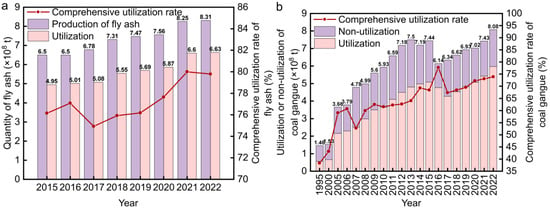
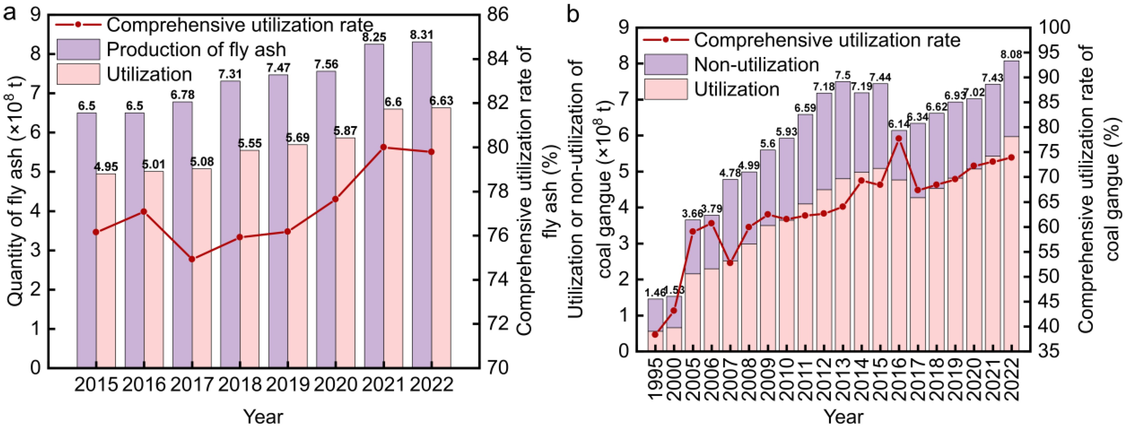
Additionally, legacy coal mines have produced large quantities of solid waste during mining and utilization, such as coal gangue from raw coal washing and beneficiation processes and fly ash from coal-fired power generation. These solid wastes pose challenges for environmental pollution [8]. Again, using China as an example, a major coal producer, the utilization of fly ash and coal gangue in recent years has been documented, as shown in Figure 1.
Figure 1.
Utilization of fly ash and coal gangue in China: (a) Utilization of fly ash; (b) Utilization of coal gangue.
Figure 1a shows that from 2015 to 2022, the production of fly ash in China exhibited a continuous upward trend. However, the comprehensive utilization rate of fly ash fluctuated between 74.93% in 2017 and 80% in 2021. The data in Figure 1a indicate that the utilization of fly ash in China is approaching saturation, highlighting the need for new utilization pathways. As shown in Figure 1b, the total production of coal gangue in China increased from 1.46 × 10⁸ t in 1995 to 8.08 × 10⁸ t in 2022, while the comprehensive utilization rate of coal gangue rose from 38.4% in 1995 to 73.9% in 2022. The data in Figure 1b indicates that despite improvements, a significant amount of coal gangue remains unutilized, with approximately 2.00 × 10⁸ t added annually. Existing treatment technologies are insufficient to meet green and low-carbon development goals.
Backfill mining, which involves replacing coal resources with solid waste materials such as fly ash and coal gangue, is an effective method for controlling surface deformation while simultaneously recycling these waste products [9,10,11]. mitigates the environmental impacts of coal mining. In recent years, a method known as CMCB (Continuous Mining and Continuous Backfilling) has been developed and applied in several mines [12,13,14,15,16,17]. The CMCB allows for the parallel execution of coal extraction and backfilling operations, thereby enhancing the recovery efficiency of residual coal resources while controlling surface deformation. During the implementation of CMCB, the mining face is divided into several parallel and adjacent roadways, similar to slicing a cake. Coal resources within each roadway are gradually replaced with backfill material by mining and filling alternating roadways with a gap of 1 to 4 roadways between them. However, during this process, the coal resources in the unmined roadways inevitably experience stress changes due to the mining and backfilling activities in adjacent roadways or coal seams [18].
Furthermore, the conditions of the roof and floor, the coal seam occurrence, and the specific CMCB schemes vary across different mines, leading to differing stability conditions in the mining area. Therefore, research on the load-bearing behavior of coal pillar and filling body during the CMCB process is crucial for the application and promotion of CMCB technology. It is important to note that as mining intensity increases and shallow, high-quality, and easily accessible coal resources become depleted, the focus of extraction is shifting deeper underground, resulting in more complex mining conditions [19]. After extensive mining, residual coal resources are often found in multiple coal seams. Thus, studying the stress evolution process in mining areas under multiple coal seam conditions is of practical significance for guiding CMCB projects.
Currently, researchers have conducted several studies on stress evolution during the replacement process of coal pillar and filling body in CMCB. For instance, Meng et al. [20]. further analyzed a short-wall paste CMCB system and verified, through numerical modeling and field measurements, that continuous mining and simultaneous backfilling significantly reduce strata movement and improve roof stability. Chen et al. [21]. studied roadway deformation mechanisms under CMCB and showed that early-age filling strength and repeated mining disturbances strongly influence roadway stability. Wang [22] investigated the stress characteristics of the filling body under a CMCB model with three roadway intervals. The research revealed that due to the repeated mining and backfilling of adjacent roadways in the CMCB process, the stress path of the filling body exhibited cyclic loading and unloading characteristics, with the stress peak gradually increasing as the CMCB process advanced. Based on these findings, triaxial cyclic loading-unloading tests with varying upper limits were conducted, revealing that such stress paths weaken the bearing capacity of the filling body. Zhu et al. [23]. studied the stress-deformation characteristics of three different types of bearing units: “coal-roadway-coal,” “filling body-roadway-coal,” and “filling body-roadway-filling body.” The study found that under uniaxial compression, the “filling body-roadway-coal” unit exhibited asymmetric deformation, which was attributed to the differing bearing capacities and stress responses of the coal and filling body on either side of the roadway. Xu et al. [24]. conducted uniaxial compression tests on coal, filling bodies of different ages, and composite specimens of “filling body-coal-filling body” with varying ages. They found that under uniaxial stress, the bearing capacity of the composite specimens depended on the increased strength of the filling body, which enhanced the coal pillar’s bearing capacity by constraining its lateral deformation during the CMCB process. These studies have established a research framework focusing on the stress evolution of CMCBSU in single coal seams, primarily utilizing uniaxial and triaxial compression tests, along with numerical simulations and rock mechanics experiments. However, there remains a lack of systematic investigation into the stress evolution of CMCBSU under close-distance coal seam conditions, where superimposed stress fields and multi-seam interactions become significant.
This study focuses on the CMCB project beneath the industrial square of the Yachen Coal Mine in Lyuliang, Shanxi Province, China, which involves the recovery of residual coal pillar resources. The research aims to investigate the load-bearing mechanism and mechanical response of the CMCBSU in close distance coal seams. To address this objective, the study integrates theoretical modeling, numerical simulation, and laboratory triaxial testing to establish a multi-scale understanding of stress evolution and failure behavior. First, the mechanical model of the CMCBSU was developed under different CMCB mining and backfilling scenarios, allowing identification of the key parameters influencing CMCBSU stability, including load partitioning, modulus contrast, and roadway geometry. Then, based on the geological conditions of the Yachen Coal Mine, a numerical model was constructed to simulate the CMCB process in close distance coal seams. The numerical model clarified the complex stress disturbances and the variations in stress peaks experienced by the CMCBSU. In particular, the σ1–σ3 stress paths extracted from numerical simulations served as the basis for designing realistic triaxial laboratory loading paths, ensuring consistency between simulated and experimental conditions.
Subsequently, stress data collected from measuring points located near the center of the CMCB area were used to design conventional triaxial compression tests and triaxial cyclic loading-unloading tests on coal, filling body, and coal–filling composite specimens that reflect different CMCB stages and loading environments. The triaxial compression tests were then analyzed to assess the impact of CMCB in close distance coal seams on the deviatoric stress–strain curves, failure modes, and mechanical properties of the CMCBSU. This combined approach allows quantitative interpretation of the collaborative load-bearing behavior between filling materials and coal pillars under multi-seam CMCB operations.
2. Engineering Background
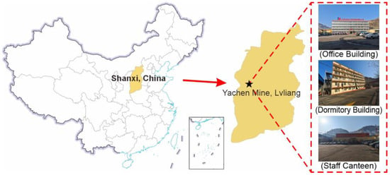
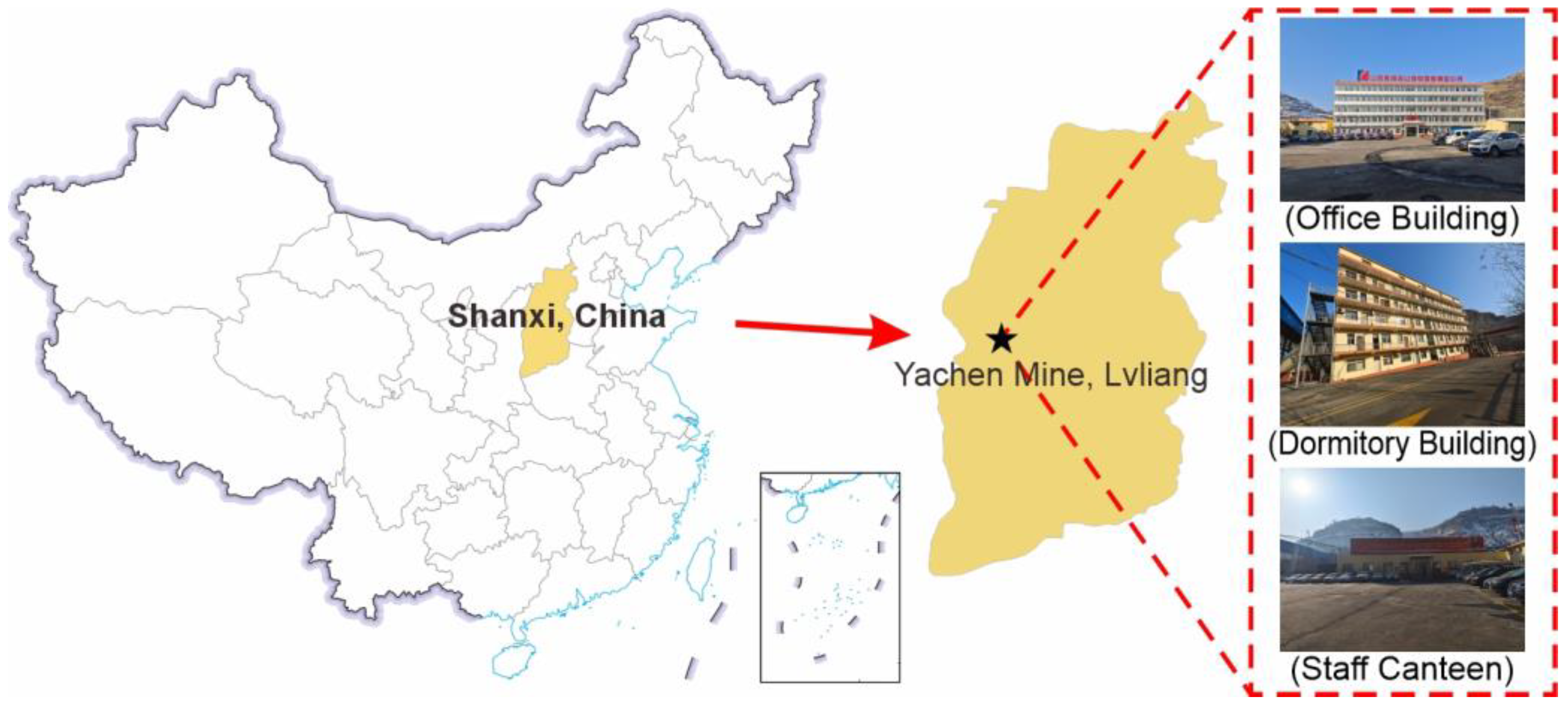
Yachen Coal Mine is located in Lyuliang, Shanxi Province, China (Figure 2). The mine is nearing the end of its operational life, necessitating the recovery of residual coal resources beneath the industrial square. The mine exploits the No. 8 and No. 9 coal seams. The No. 8 coal seam has a thickness ranging from 3.13 to 3.60 m, with an average thickness of 3.22 m. In the No. 8 coal seam, each roadway has a width of 4.5 m and a height of 3.22 m, and there are 24 roadways in total. The No. 9 coal seam has a thickness ranging from 3.80 to 4.55 m, with an average thickness of 4.02 m. In the No. 9 coal seam, each roadway has a width of 4.0 m and a height of 4.02 m, and there are 27 roadways in total. The average burial depth of the No. 8 coal seam is 113.28 m, while the No. 9 coal seam has an average burial depth of 125.6 m. The interlayer spacing between the No. 8 and No. 9 coal seams is 8.3 m, and the coal seams dip gently at 3–7°, forming a typical close-distance coal seam group. In the process of roadway excavation, conventional support such as bolt or metal frame is used, but it is mainly used as a temporary support measure before the backfill body reaches strength.
Figure 2.
Location of the Yachen Coal Mine.
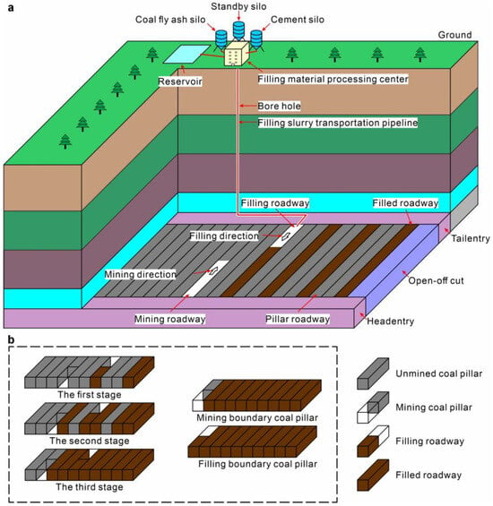
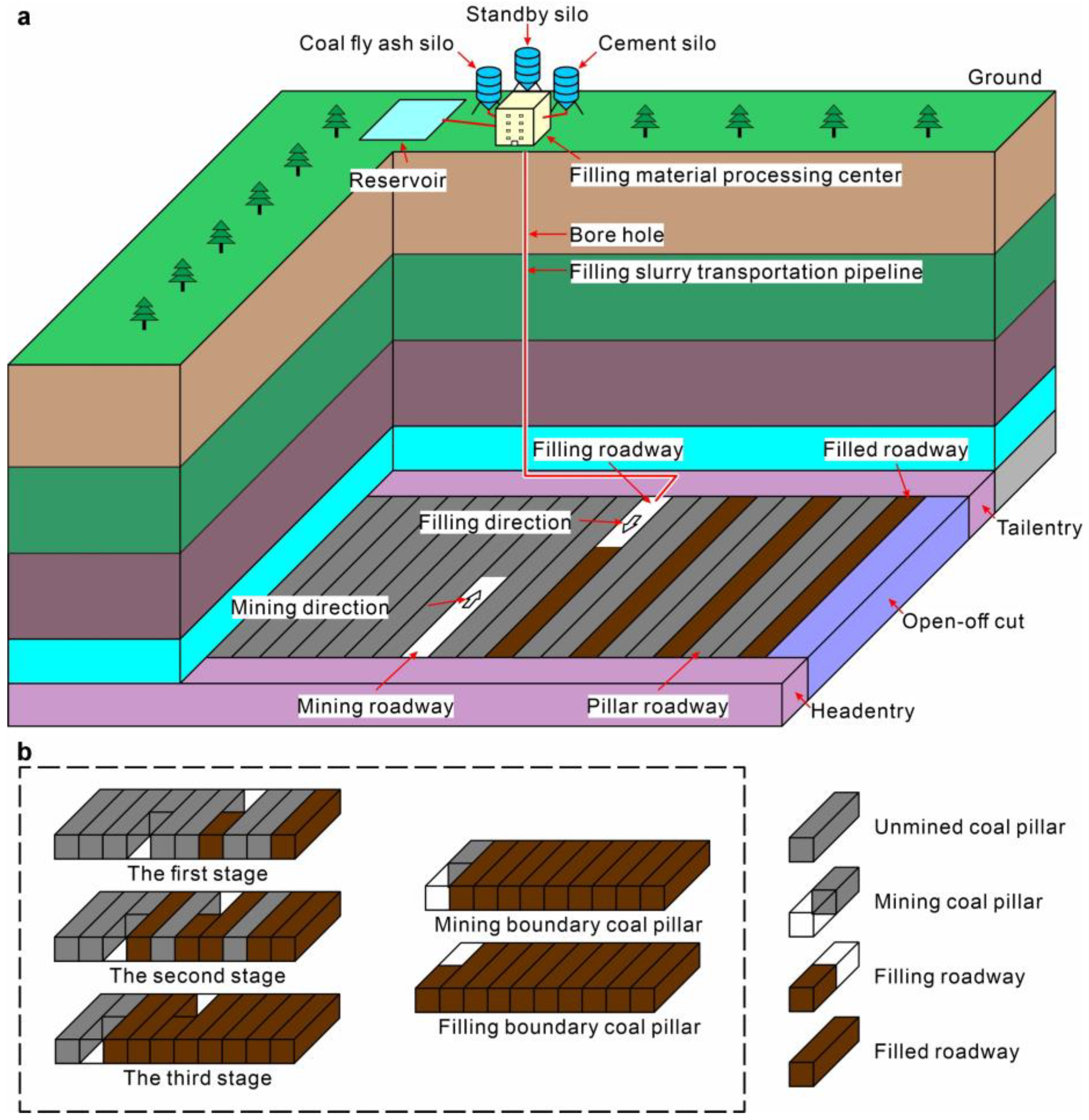
The recovery of residual coal pillars at the Yachen Coal Mine utilizes the CMCB technology. The operation of CMCB primarily depends on three key components: the surface backfill slurry processing center, the slurry transportation system, and the underground backfill mining system (Figure 3a). Solid wastes, such as fly ash and coal gangue produced during coal mining and processing, are processed into backfill slurry at the surface backfill slurry processing center. The slurry is then pressurized and transported to the underground workface via the slurry transportation system. The underground backfill mining system consists of headentry, tailentry, open-off cut, and multiple parallel CMCB working roadways of the same width.
Figure 3.
Technical flow of CMCB: (a) System composition of CMCB; (b) Process mode of CMCB. Grey represents the degree of unexcavated roadway, and brown represents the degree of roadway filling.
The CMCB working roadways are sequentially named based on the stage of the CMCB process and the operational order of the roadways over time: pillar roadway, mining roadway, filling roadway, and filled roadway. Taking the Yachen Coal Mine’s CMCB model with two roadway intervals as an example (Figure 3b), a temporary protective coal pillar is left along the boundary of the CMCB area adjacent to the main roadway. Each layer of coal is mined and backfilled in three main stages, followed by a completion stage. During the first stage, roadways 1, 4, 7, and so on are mined sequentially. After the completion of mining in each roadway, the next roadway is immediately mined, ensuring synchronization between mining and backfilling operations. After all roadways in the first stage are mined and backfilled, the last roadway filled in this stage undergoes a 28-day curing period to ensure sufficient early strength prior to the second-stage operations. The second stage follows the sequence of roadways 2, 5, 8, and so on.
Similarly, after completing the second stage, the last roadway filled is allowed to cure for 28 days before starting the third stage of CMCB operations, with the sequence of roadways 3, 6, 9, and so forth. After the completion of the first three main stages, the temporary protective coal pillar is extracted and replaced by backfill material. A 28-day curing period ensures that the filling body reaches the required strength, completing the CMCB process for one coal seam layer. This method is then sequentially applied to both the No. 8 and No. 9 coal seams following the same CMCB procedures.
Based on the mine data, the physical and mechanical parameters of the main rock layers have been compiled and are presented in Table 1. These parameters will be utilized in the subsequent construction of numerical models.
Table 1.
Physical and mechanical parameters of coal and rock mass.
3. Mechanical Load-Bearing Model for CMCBSU
Mine monitoring data indicate that after the excavation of each roadway in the CMCB area, a phenomenon known as “rib spalling” occurs on the coal wall side of the roadway due to stress release. The extent of rib spalling is influenced by factors such as the timing and strength of roadway support. In contrast, roof-fall events were not observed during the excavation process, which is consistent with the presence of a competent and thick limestone roof at Yachen Mine. As the primary support medium replacing coal pillars within the CMCB area, the filling body initially provides low support to the roof when it is first placed into the roadway because it has not yet reached its final strength. During this period, the filling body offers inadequate support to the surrounding rock, and the coal pillars surrounding the filling body tend to deform due to the lack of an ideal triaxial stress state. As the strength of the filling body gradually increases and the surrounding rock deforms, the filling body comes into close contact with the surrounding rock. Over time, both the filling body and the adjacent coal pillars begin to jointly bear the load, enhancing the overall support of the excavation area.
The form of the CMCBSU varies at different stages of the CMCB process. In the case of the CMCB model with two roadway intervals, every three adjacent roadways constitute a single CMCBSU. As the CMCB process progresses, the proportion of the filling body within the CMCB area gradually increases while the proportion of coal pillars decreases. To analyze the load-bearing mechanism of CMCBSU at different CMCB stages, we consider the similarity between the CMCB method and strip mining: the excavation length of the roadway is much greater than the width, so the loading condition of the CMCBSU can be considered a plane problem. Based on this consideration and using the Wilson progressive failure theory, a mechanical model of the CMCBSU under load is constructed.
It should be noted that the applicability of the proposed mechanical model is inherently dependent on the stability of the roof strata. Previous studies have demonstrated that when the roof maintains overall integrity and no large-scale roof collapse occurs, the load-bearing behavior of mine roadways can be reasonably analyzed using simplified structural mechanics approaches. In particular, Sakhno et al. [25] established that roof stability, support condition, and anchoring effectiveness are the dominant controlling factors governing roof failure risk in underground coal mine roadways, and that stable or moderately stable roof conditions allow the load transfer to be primarily controlled by coordinated deformation rather than progressive roof collapse. Under such conditions, the roof support system exhibits a continuous load redistribution process without abrupt structural failure, which supports the use of equivalent mechanical models to describe the global load-bearing response. Therefore, the mechanical model proposed in this study is applicable to CMCB conditions with a competent roof, such as the thick limestone roof observed at the Yachen Coal Mine.
3.1. Configuration of the CMCBSU
In a CMCB layout with two roadway intervals, every three adjacent roadways constitute a single CMCBSU. As mining proceeds, the proportion of filling bodies increases and the proportion of coal pillars decreases. Given the roadway geometry—where the excavation length is much greater than its width—the CMCBSU can be analyzed using a plane strain approximation. Based on the analogy between the CMCB method and strip mining, and using Wilson’s progressive failure theory, a mechanical model representing the loading conditions of the CMCBSU is constructed.
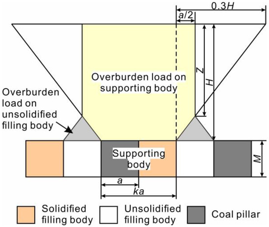
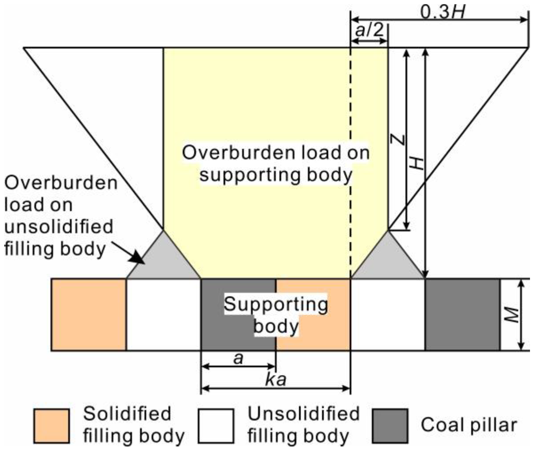
Figure 4 illustrates the loading conditions of the load state diagram of the CMCBSU in the CMCB model with two roadway intervals. In Figure 4, is the mining height of the coal seam, m. is the burial depth of the coal seam, m. is the width of the roadway, m. is the determination coefficient of the CMCB mode, where for the CMCB model with one roadway intervals, for the CMCB model with two roadway intervals, and so forth. The adjacent orange, white, and dark gray roadways in Figure 4 together form a CMCBSU. The filling body in the white area has not yet reached its final strength and is, therefore, considered a void. According to Wilson’s progressive failure theory, the load on the CMCBSU is represented by the area of the yellow region in Figure 4.
Figure 4.
The load state diagram of the CMCBSU.
The CMCB mining method ensures that there are always different forms of load-bearing units within the CMCBSU. For instance, in the CMCB model with two roadway intervals, the first stage of CMCB consists of a “coal-coal” combination, the second stage comprises a “coal-filling body” combination, and the third stage involves a “filling body-filling body” combination. Figure 4 corresponds to the second stage in the CMCB model with two roadway intervals.
3.2. Load Calculation of the CMCBSU
According to the theory of similar triangles:
where is the width of the roadway, m; is the burial depth of the coal seam, m.
Therefore, the load borne by the CMCBSU can be expressed as:
where is the average unit weight of the overlying rock strata, typically taken as 25 kN·m−3.
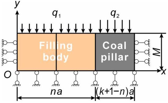
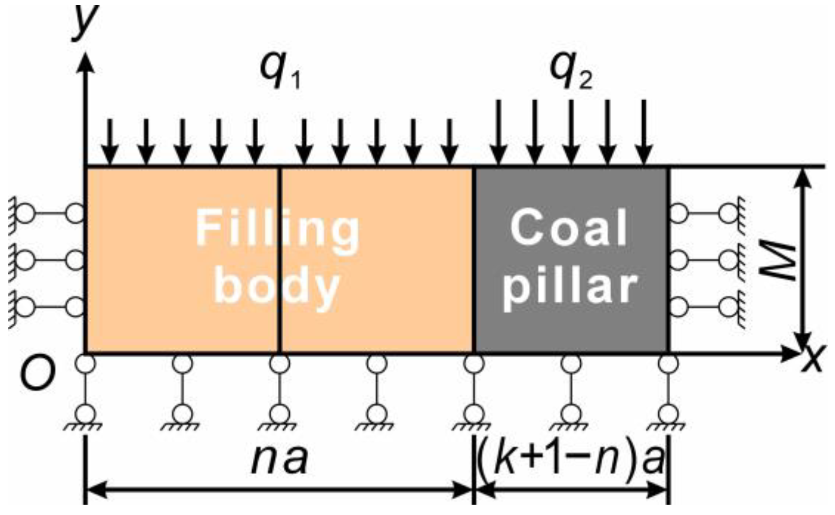
When all the filling bodies in this stage reach the desired support strength, the loading condition of the CMCBSU is as shown in Figure 5, where is the stage determination coefficient of the CMCB process, , with for the first stage, for the second stage, for the third stage, and so on.
Figure 5.
The mechanical model of the CMCBSU.
In Figure 5, the displacement boundary conditions for the mechanical model of the CMCBSU are as follows:
The stress boundary conditions for the mechanical model of the CMCBSU are as follows:
Assuming that the roof subsidence during the solidification period of the filling body in each roadway is negligible, a close approximation can be obtained by combining Equation (2) with Figure 5:
As mentioned at the beginning of this section, the inconsistency in mechanical strength between the filling body and the coal pillar can lead to asymmetric deformation of the surrounding rock. Therefore, to ensure the effectiveness of CMCB operations, it is ideal for the adjacent coal pillar and filling body to undergo synchronous deformation. Assuming that the vertical displacements of the adjacent coal pillars and filling bodies are equal, the following relationship can be derived from Hooke’s law:
where and are the elastic moduli of the filling body and coal pillar, respectively, MPa; and are the vertical displacements of the filling body and coal pillar, respectively, m.
It can be derived from Equation (6) that:
The substitution of Equation (5) into Equation (7) yields:
For the CMCB model with two roadway intervals, where and m, the load on the CMCBSU can be simplified to using Equation (2). Substituting the simplified load on the CMCBSU into Equation (8) yields:
The loads experienced by the CMCBSU at different stages for the CMCB model with two roadway intervals are:
The first stage:
The second stage:
The third stage:
Based on Equations (2), (6) and (9) through Equation (12), it can be determined that the load experienced by the CMCBSU is primarily influenced by the elastic moduli of the coal pillar and the filling body, the depth of the coal seam, and the width of the roadway. Among these factors, the similarity in elastic modulus between the coal pillar and the filling body is a crucial determinant of the load and deformation experienced by both. A higher similarity in elastic moduli results in more stable surrounding rock. When the elastic moduli of the coal and filling material are identical, increases in roadway width, overburden density, and mining depth all lead to greater loads and deformations on the coal pillar and filling material. Therefore, during the design phase of the CMCBS project, it is crucial to ensure the mechanical similarity between the filling body and the coal pillar and to consider reducing the roadway width to minimize roof subsidence.
3.3. Assumptions and Applicability of the Mechanical Model
To enhance clarity, the key assumptions used in the mechanical model and their applicability to the Yachen Mine conditions are summarized and justified as follows:
- (1)
- Plane strain assumption.
The excavation length of each CMCB roadway (>300 m) is much greater than its width (≈4–4.5 m). The deformation and loading characteristics are therefore dominated by the longitudinal uniformity, making plane strain a valid first-order approximation.
- (2)
- Neglecting roof subsidence during early curing (Equation (5)).
Field monitoring confirmed no roof-fall events and minimal roof convergence during excavation, due to the presence of a thick and competent limestone roof (UCS ≈ 90 MPa). Thus, early-stage subsidence is negligible within the 28-day curing period.
- (3)
- Elastic constitutive model for coal and filling body.
Although both materials exhibit nonlinear deformation at high stress, the model focuses on the initial loading stages that determine stress distribution. Elastic assumptions have been widely used in preliminary evaluations of roadway–pillar systems under similar conditions.
- (4)
- No explicit modeling of plastic or fractured zones.
This study aims to capture large-scale load transfer across the CMCBSU rather than localized failure processes. Plastic zones and fractured zones are fully addressed later in the numerical simulation section, complementing the analytical model.
- (5)
- Treatment of newly filled roadways as voids (Figure 4).
This assumption is consistent with the measured low early-stage stiffness of filling slurry (compressive strength < 1 MPa before curing). It is only applied to the curing stage and not to long-term evaluations.
- (6)
- Influence of close-distance coal seams.
The small interlayer spacing (≈8.3 m) induces vertical stress superposition between the No. 8 and No. 9 seams. Therefore, the mechanical model includes the complete burial depth in stress calculations, ensuring that the multi-seam effects are incorporated into the analytical framework.
- (7)
- Limitations and planned improvements.
Future work will incorporate time-dependent curing behavior, nonlinear constitutive laws, and fracture evolution to further refine the load-bearing predictions.
4. Stress Characteristics of CMCBSU
4.1. Numerical Model
To obtain the complex stress variation characteristics experienced by CMCBSU during the CMCB process in close distance coal seams, numerical simulation studies based on FLAC3D were conducted. The No. 8 and No. 9 coal seams beneath the Yachen Coal Mine were used as the engineering background for this research.
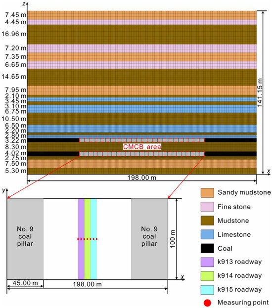
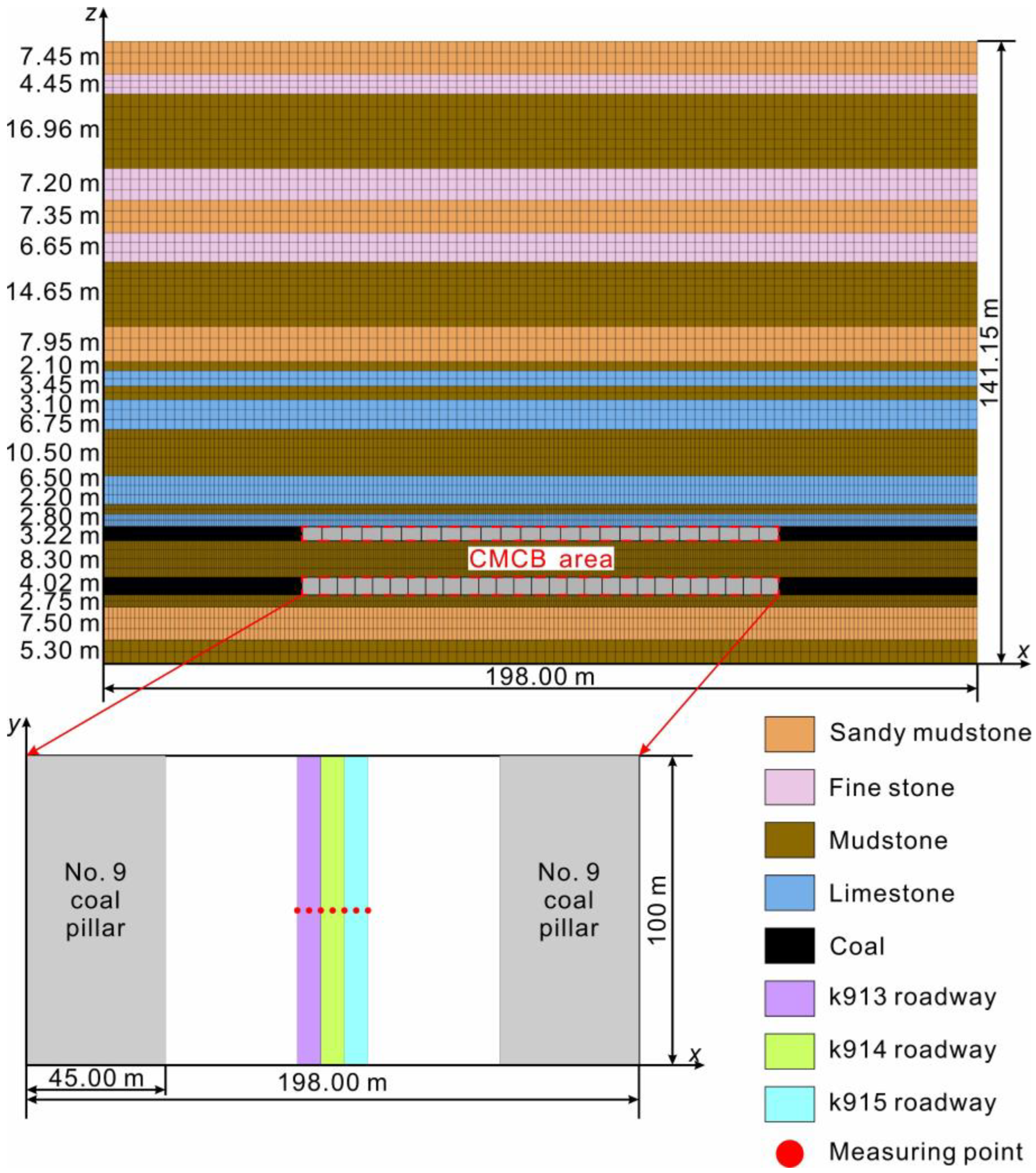
Figure 6 presents the basic information of the numerical calculation model for CMCB with two roadway intervals. The dimensions of the model are 198.00 m × 100 m × 141.15 m. The boundaries of the model are set as fixed displacement on the sides and bottom, while the top is defined as a free boundary. All rock layers are assigned Mohr–Coulomb constitutive behavior, and their mechanical parameters are obtained from field exploration and laboratory testing (Table 2). In the No. 8 coal seam, each roadway has a width of 4.5 m and a height of 3.22 m, and there are 24 roadways in total. In the No. 9 coal seam, each roadway has a width of 4.0 m and a height of 4.02 m, and there are 27 roadways in total. A 45 m coal pillar is reserved on both sides of the CMCB area in both No. 8 coal seam and No. 9 coal seam. For ease of describing the experimental results, the roadways in the No. 8 and No. 9 coal seams are named sequentially from left to right. For example, the leftmost roadway in the No. 8 coal seam is designated as k801, and the rightmost is k824. Similarly, the leftmost roadway in the No. 9 coal seam is designated as k901, and the rightmost is k927. The model sequentially excavates No. 8 and No. 9 coal seams. The mining and backfilling sequence of the roadways within the coal seams is illustrated in Figure 3b.
Figure 6.
Numerical simulation model for the CMCB model with two roadway intervals. The red dashed frame represents the CMCB area.
Table 2.
Physical and mechanical parameters of coal strata.
This study focuses on the k913, k914, and k915 roadways in the No. 9 coal seam, which together constitute a CMCBSU under the CMCB model with two roadway intervals. Throughout the different stages of CMCB, the CMCBSU undergoes three distinct configurations: “filling body-coal pillar-coal pillar,” “filling body-filling body-coal pillar,” and “filling body-filling body-filling body.” To analyze the stress variations in the CMCBSU during different stages in the close distance coal seams, stress measuring points were installed in the center of a mining–backfilling block, located at the roof between roadways 913, 914, and 915. A total of eight measuring points were installed in each roadway, with a spacing of 0.5 m between adjacent points, as shown in Figure 6.
4.2. Numerical Simulation Results and Analysis
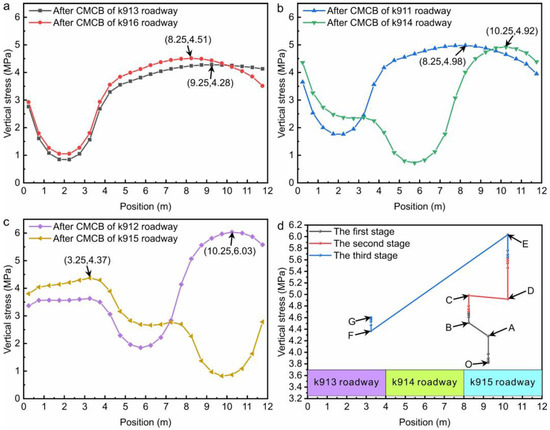
Figure 7a–c illustrates the stress distribution at the measuring points of CMCBSU. The time frame considered begins when the first roadway of the CMCBSU completes the CMCB process and ends when the last roadway of the CMCBSU completes the CMCB process.
Figure 7.
The stress of the measuring points located at the center of the CMCB area in the No. 9 coal seam during the CMCB process: (a) The first stage of CMCB; (b) The second stage of CMCB; (c) The third stage of CMCB; (d) The location of the maximum vertical stress in each stage of CMCB.
As shown in Figure 7b, after the completion of the CMCB process in the k911 roadway, a stress peak of 4.98 MPa appeared on the left side of the k915 roadway within the CMCBSU. Figure 7c indicates that after the CMCB process in the k912 roadway, a stress peak of 6.03 MPa appeared in the middle of the k915 roadway within the CMCBSU. A comprehensive analysis of Figure 7a–c reveals that the vertical stress in the coal pillar within the CMCBSU increases continuously before the CMCB process due to factors such as roof subsidence and deformation. After the CMCB process, the coal pillar is replaced by the filling body, causing the stress to gradually increase from 0 MPa until the stress in the CMCB area rebalances upon the completion of the CMCB process.
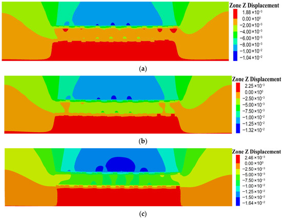
To further investigate the deformation behavior induced by continuous mining and continuous backfilling in close-distance seams, Figure 8a–c presents the vertical displacement contours of the overlying strata during the first, second, and third stages of the CMCB process in the No. 9 coal seam.
Figure 8.
The stress distribution patterns in the No. 9 coal seam during the CMCB process: (a) The first stage of CMCB; (b) The second stage of CMCB; (c) The third stage of CMCB.
Figure 8a shows the displacement field after completion of the first-stage CMCB roadways. Minor roof sagging occurs directly above the mined-out and backfilled roadways, and localized subsidence zones begin to form.
Figure 8b illustrates the deformation pattern after the second-stage CMCB roadways are completed. The roof deformation zone becomes more pronounced, and the extent of subsidence increases. Stress transfer toward the unmined middle roadways intensifies, consistent with the stress peaks observed in Figure 7b,c.
Figure 8c displays the deformation after the third-stage roadways are completed. At this stage, most of the CMCB area has been backfilled, and the displacement field shows a more continuous subsidence basin. The stress within the central coal pillar (k913) tends to stabilize as the backfill begins to share a larger portion of the load.
Figure 8 reveals that the overlying strata undergo progressively intensified and continuous subsidence during the CMCB process, with the deformation magnitude increasing as the stages advance. The subsidence troughs observed in Figure 8 correspond closely to the stress concentration zones in Figure 7, indicating that the cyclic disturbances induced by staged excavation and backfilling are transmitted to the central CMCBSU, leading to repeated stress fluctuations.
Figure 7d illustrates the changes in the peak magnitude and position of vertical stress in the CMCBSU after the completion of the CMCB process. In segment OA, which corresponds to the completion of the first stage of CMCB for the k901, k904, k907, k910, and k913 roadways, the peak vertical stress within the CMCBSU increases from 3.82 MPa to 4.28 MPa, with the peak stress point located within the k915 roadway. Segment AB represents the result of the first stage of CMCB in the k916 roadway, where the peak vertical stress increases from 4.28 MPa to 4.51 MPa, with the peak stress point shifting towards the left side within the k915 roadway. In segment BC, corresponding to the completion of the first stage of CMCB for the k919, k922, and k925 roadways and the second stage for the k902, k905, k908, and k911 roadways, the peak vertical stress increases from 4.51 MPa to 4.98 MPa, with no change in the peak stress point location. Segment CD pertains to the second stage of CMCB in the k914 roadway, during which the peak vertical stress slightly decreases from 4.98 MPa to 4.92 MPa, and the peak stress point shifts towards the right side within the k915 roadway, moving closer to the center of the k815 roadway compared to segment OA. Segment DE reflects the completion of the second stage of CMCB for the k917, k920, k923, k926 roadways and the third stage for the k903, k906, k909, k912 roadways, where the peak vertical stress increases from 4.92 MPa to 6.03 MPa, with no change in the peak stress point location. Finally, segment EF corresponds to the third stage of CMCB in the k915 roadway, during which the peak vertical stress decreases from 6.03 MPa to 4.37 MPa, with the peak stress point shifting from the k915 roadway to the k913 roadway. Segment FG pertains to the completion of the third stage of CMCB for the k918, k921, k924, and k927 roadways, where the peak vertical stress increases from 4.37 MPa to 4.60 MPa, with no change in the peak stress point location.
Based on the analysis of Figure 7a–c, it is evident that during the CMCB process in the No. 9 coal seam, the CMCBSU was subjected to cyclic stress disturbances from left to right. The stress at measuring points located in the k913, k914, and k915 roadways showed a continuous increase before the CMCB process. After the CMCB process, the stress at these measuring points dropped to 0 MPa and then began to rise again. Furthermore, the analysis of Figure 7d indicates that after the CMCB process, the stress in the CMCB area was redistributed, with the vertical stress reaching its maximum at the k913 roadway in the center of the CMCB area. These phenomena are closely related to the intermittent and cyclic nature of the CMCB process. This stressful environment can have adverse effects on the stability of both the coal pillar and the filling body within CMCBSU during different stages of the CMCB process.
5. Mechanical Behavior of CMCBSU
5.1. Experiment Method
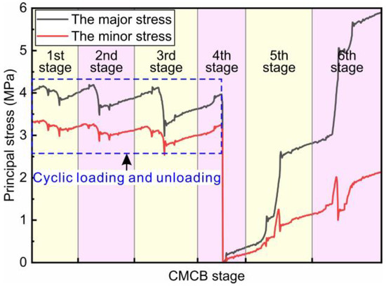
To analyze the adverse effects of complex stress disturbances generated by the CMCB process on the stability of CMCBSU in close distance coal seams, stress measuring points located at the center of the k913 roadway, as shown in Figure 6, were used as the basis. The maximum principal stress and minimum principal stress at these measuring points within the k913 roadway were collected during the entire CMCB process in the No. 8 and No. 9 coal seams, as illustrated in Figure 9. The data come from the historical stress monitoring points in the numerical simulation.
Figure 9.
The variation in maximum principal stress and minimum principal stress at the measuring point of the k913 roadway during the CMCB process.
Figure 9 illustrates the and measurements at various measuring points in the k913 roadway of the No. 9 coal seam during the entire CMCB process. Due to the CMCB model adopted by the Yachen Coal Mine, which involves the CMCB method with two roadway intervals and the extraction of both the No. 8 and No. 9 coal seams, the CMCB process is divided into six stages: the first three stages correspond to the CMCB of the No. 8 coal seam. In contrast, the latter three stages correspond to the No. 9 coal seam. Within the blue dashed region, the and measurements in the k913 roadway exhibit cyclical loading and unloading behavior. The decline observed in the and values during these cycles is related to the fact that the k913 roadway is located within the influence zone of mining activities in the No. 8 coal seam.
After the completion of mining and filling operations in the k913 roadway, and generally show a continuous increase until the completion of the CMCB process for all roadways in the No. 9 coal seam.
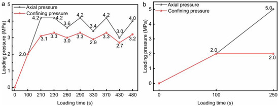
During the CMCB process in close distance coal seams, the combination forms and stress characteristics of CMCBSU can be categorized into the following stages: the “coal pillar-coal pillar-coal pillar” cyclical loading and unloading stage, the “filling body-filling body-filling body” loading stage, the “filling body-filling body-coal pillar” loading stage, and the “filling body-filling body-filling body” loading stage. To investigate the collaborative bearing characteristics of the filling body and coal pillar, the and in Figure 8 are equivalently represented as axial and confining pressures, respectively, and are simplified as conventional triaxial compression test paths, as shown in Figure 9.
Figure 10a illustrates the loading and unloading path of the triaxial cyclic loading-unloading test on coal samples. The preloading phase, ranging from 0 to 2 MPa, was conducted with an axial pressure and confining pressure loading rate of 0.02 MPa/s. Beyond 2 MPa, to ensure the synchronization of stress application, the axial pressure was applied and released at a rate of 0.02 MPa/s. In contrast, the confining pressure was applied and released at a rate of 0.01 MPa/s. After 480 s of loading, the confining pressure was held constant, and the axial pressure was applied at a rate of 0.02 MPa/s until the specimen failed.
Figure 10.
Stress path for the co-bearing characteristic test: (a) Triaxial cyclic loading and unloading test on coal (TCLU-coal); (b) Conventional triaxial compression test on coal (CTC-coal), filling body (CTC-fb) and the combination of coal and filling body (CTC-ccfb).
Figure 10b presents the loading paths of conventional triaxial compression tests for coal, filling body, and the combination of coal and filling body samples. The preloading phase, ranging from 0 to 2 MPa, was conducted with an axial pressure and confining pressure loading rate of 0.02 MPa/s. Beyond 2 MPa, the confining pressure was kept constant, and the axial pressure was applied at a rate of 0.02 MPa/s until the specimen failed.
5.2. Specimen Preparation and Test Instrument
The fly ash and cement required for casting the backfill specimens were sourced from the Yachen Coal Mine. The mass ratio of fly ash to cement was 3:1, and the water-to-solid ratio was 4:5. The backfill specimens were demolded 48 h after casting. Then they were cured in a constant temperature and humidity chamber at 25 °C and 95% humidity for 28 days. The coal used was obtained from the No. 9 coal seam of the Yachen Coal Mine, classified as coking coal. Both the coal and backfill specimens were prepared according to ISRM recommendations, with dimensions of Φ50 × 100 mm.
Considering that in the CMCB process of Aachen Coal Mine, waterproof plastic sheets are used to separate the coal body from the filling body to prevent direct contact between the two, and the bleeding process of the filling body will not affect the coal body. Therefore, the composite specimen is to cut each filling body and coal sample in half along the axial direction and then connect them directly. In order to achieve fixation, a small amount of epoxy resin was used to bond between the two semi-cylindrical specimens, which were fixed by a rubber band and placed in a curing box at 25 degrees Celsius for 24 h. The epoxy resin bonding ensures that the mechanical properties of the interface are not enhanced, thus simulating the weak interface characteristics caused by the plastic film in the field. The triaxial cyclic loading and unloading tests on the coal specimens, conventional triaxial compression tests on the coal specimens, conventional triaxial compression tests on the filling body specimens, and conventional triaxial compression tests on the combined specimens each included three samples, totaling 12 specimens.
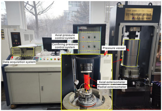
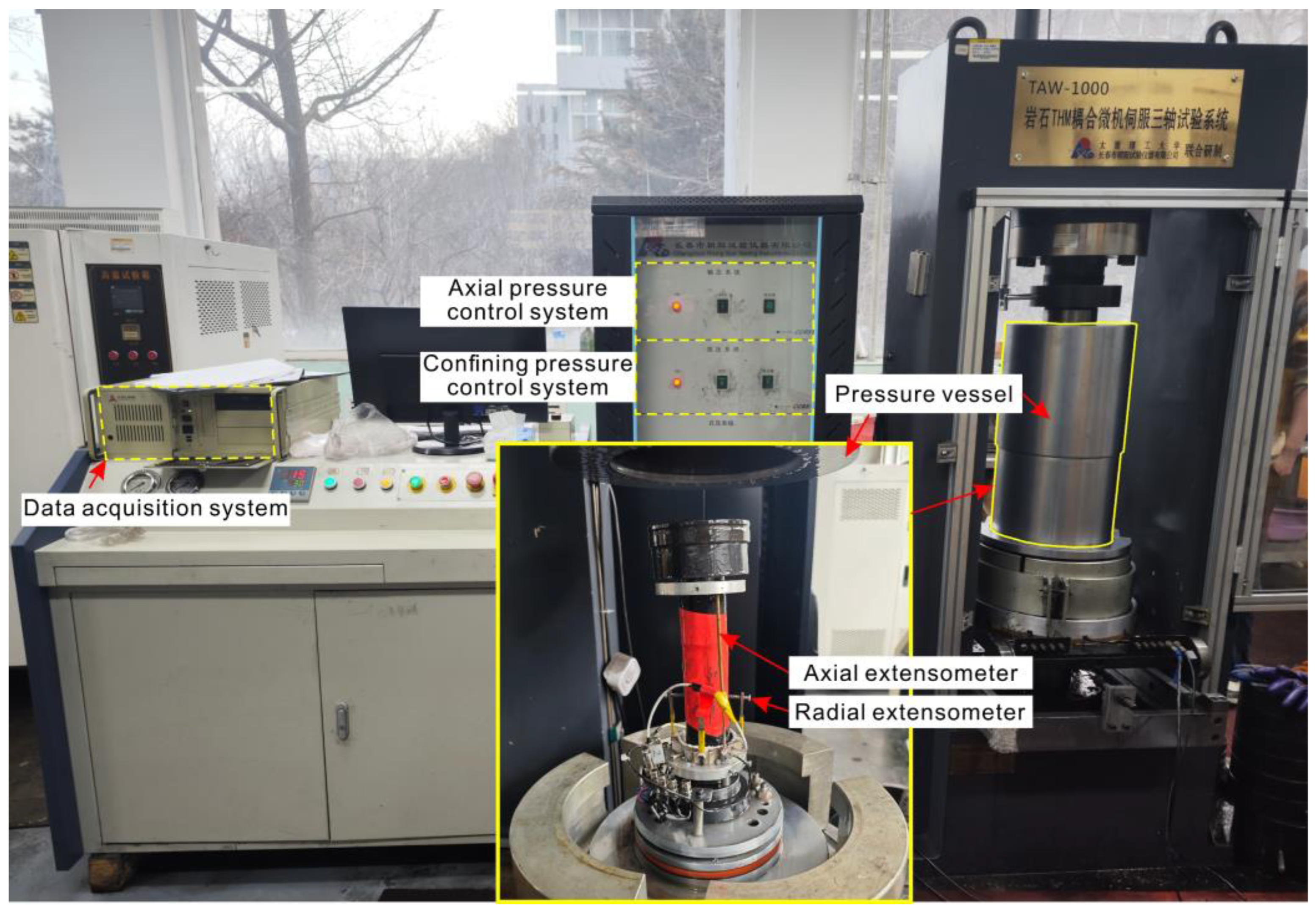
The experimental equipment used in this study is the Rock THM Coupled Microcomputer Servo Triaxial Testing Machine from the Key Laboratory of In situ Property-Improving Mining of Ministry of Education at Taiyuan University of Technology (Figure 11). The mechanical module was utilized for the experiment, which primarily includes the axial pressure control system, confining pressure control system, strain measurement system, and data acquisition system. The axial pressure control system was used to apply and release axial pressure on the specimen. In contrast, the confining pressure control system controlled the injection or extraction of silicone oil into or from the sealed chamber to apply and release confining pressure. The experimental procedure consisted of the following steps:
Figure 11.
Rock THM coupled microcomputer servo triaxial testing machine.
1. Specimen Installation: The specimen and spacers were sequentially placed on the base. The specimen was then wrapped in a heat-shrink tube, with the ends secured using tape to ensure that hydraulic silicone oil would not penetrate the specimen during the experiment. The axial extensometer base, radial extensometer, and axial extensometer were successively installed. The prepared specimen was then placed into the pressure vessel, and the installation of the specimen and monitoring devices was completed.
2. Equipment Fixation: The specimen with the installed monitoring devices was placed into the pressure vessel. The pressure vessel was then moved to align directly under the testing machine.
3. Experimental Loading: The loading parameters for the specimen were input into the software, and the triaxial compression test was initiated, during which stress, strain, and other experimental data were collected.
5.3. Experimental Results and Analysis
5.3.1. Characteristics of Deviatoric Stress–Strain Curve
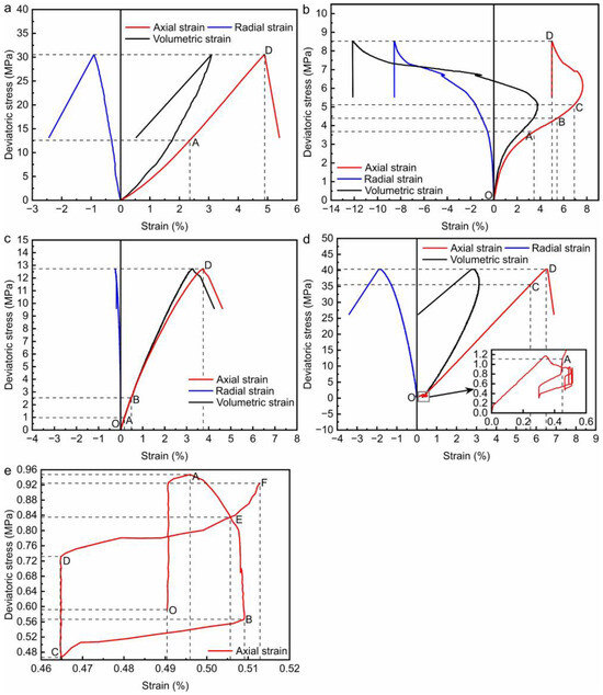
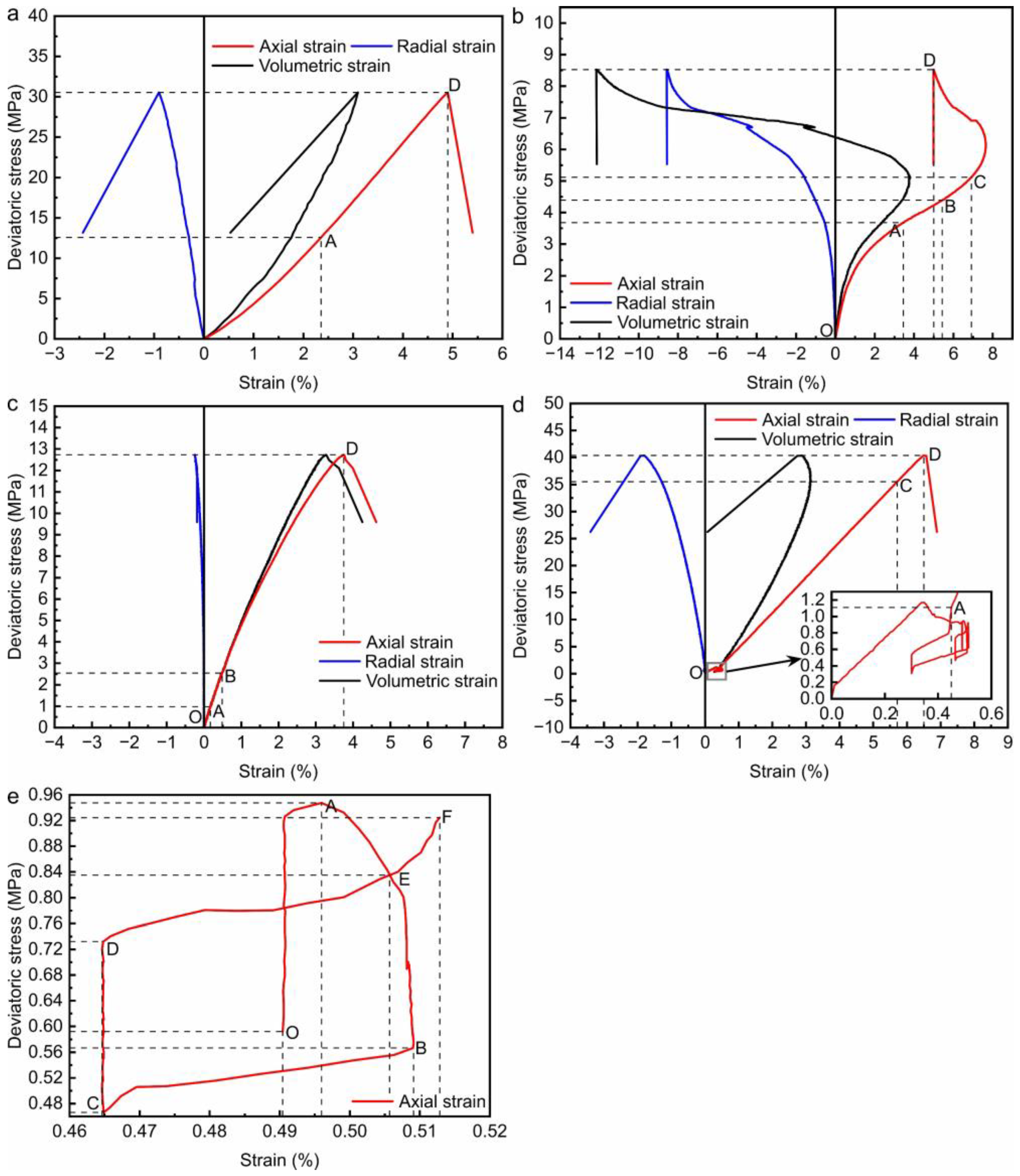
Figure 12 presents a set of representative deviatoric stress–strain curves. In Figure 12, the red curve represents the relationship between deviatoric stress and axial strain, the blue curve corresponds to the relationship between deviatoric stress and radial strain, and the black curve illustrates the relationship between deviatoric stress and volumetric strain. Based on the strain curve method [26,27,28,29], the deviatoric stress–strain curves are tentatively divided into several stages. In this study, compressive stress is defined as positive, tensile stress as negative, compressive deformation as positive, and tensile deformation as negative.
Figure 12.
Stress-strain curves for coal and backfill under different loading schemes: (a) Conventional triaxial compression of coal; (b) Conventional triaxial compression of filling body; (c) Conventional triaxial compression of the combination of coal and filling body; (d) Triaxial cyclic loading and unloading of coal; (e) A hysteresis loop curve of triaxial cyclic loading and unloading of coal.
Figure 12a illustrates the deviatoric stress–strain curve for coal under conventional triaxial compression. The OA segment of the deviatoric stress-axial strain curve represents the compaction stage of pore and fracture closure in the coal body, characterized by a gentle concave trend. During this phase, the pre-existing tensile structures within the coal gradually close. The AD segment of the curve is approximately linear, indicating that the coal exhibits distinct brittleness before failure.
Figure 12b shows the deviatoric stress–strain curve for the filling material under conventional triaxial compression. The OA segment of the deviatoric stress-axial strain curve displays a convex trend, suggesting the occurrence of strain softening in the filling body [30]. The AB segment of the curve is nearly linear. Starting from point B, both the axial compression and volumetric compression of the filling body begin to decelerate. At point C, the volumetric behavior of the filling body transitions from compression to expansion. The BD segment exhibits a decreasing trend in axial strain compression and an increasing trend in radial expansion, which can be attributed to the combined effect of radial expansion induced by increased axial stress, leading to a localized reduction in axial strain.
Figure 12c presents the deviatoric stress–strain curve for the composite under conventional triaxial compression. Prior to the stress peak at point D, the overall deviatoric stress-axial strain curve shows a trend of strain softening, with a gradual decrease in elastic modulus. The AB segment is approximately linear. The increase in volumetric strain can be attributed to the combined effect of the volumetric strain changes in both the coal and the filling body.
Figure 12d illustrates the deviatoric stress–strain curves of coal under triaxial cyclic loading and unloading. The enlarged view of the cyclic loading and unloading region in Figure 12d reveals a V-shaped distribution in the deviatoric stress-axial strain curve during the first unloading and reloading process, corresponding to the axial stress range of 4.2 MPa → 3.6 MPa → 4.2 MPa and the confining pressure range of 3.3 MPa → 3.0 MPa → 3.3 MPa as shown in Figure 10a. Within this V-shaped region, the axial strain of the coal specimen increases by only 0.01%, with negligible change in radial strain. In contrast, hysteresis loops are observed in the deviatoric stress-axial strain curves during the second and third unloading and reloading processes. Following the cyclic loading and unloading stages, the deviatoric stress-axial strain curve reaches point D in an approximately linear manner. Compared to the conventional triaxial compression test of coal, the cyclic loading and unloading test shows a distinct volumetric expansion point C on the deviatoric stress-volumetric strain curve, where the deviatoric stress corresponds to the dilatancy strength of the coal.
Figure 12e presents the deviatoric stress-axial strain curve for coal under triaxial cyclic loading and unloading, considering one complete cycle of “loading-unloading-reloading.” As shown in Figure 12e, the OABCDEF curve represents an entire cycle of loading, unloading, and reloading, where segment OA of the loading curve corresponds to the right half of the V-shape observed during the first unloading and reloading process in Figure 12d. Segments AB and BC of the unloading curve correspond to the axial stress range of 4.2 MPa → 3.4 MPa and the confining pressure range of 3.3 MPa → 2.9 MPa, respectively, as shown in Figure 10a. Segments CD and DF of the loading curve correspond to the axial stress range of 3.4 MPa → 4.2 MPa and the confining pressure range of 2.9 MPa → 3.3 MPa, respectively, as shown in Figure 10a. A comparison of the unloading curve segment AC with the loading curve segment CF indicates elastic hysteresis in both the loading and unloading processes [31,32], as the loading and unloading curves do not overlap, forming a closed loop EBCDE. This indicates that the cyclic loading and unloading occurs within the elastic region of the coal specimen. The observation that the initial loading point O is higher than the unloading endpoint C is attributed to the specific loading-unloading path.
5.3.2. Characteristics of Specimen Failure
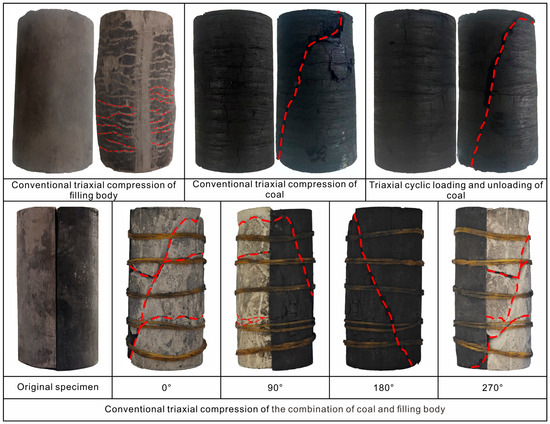
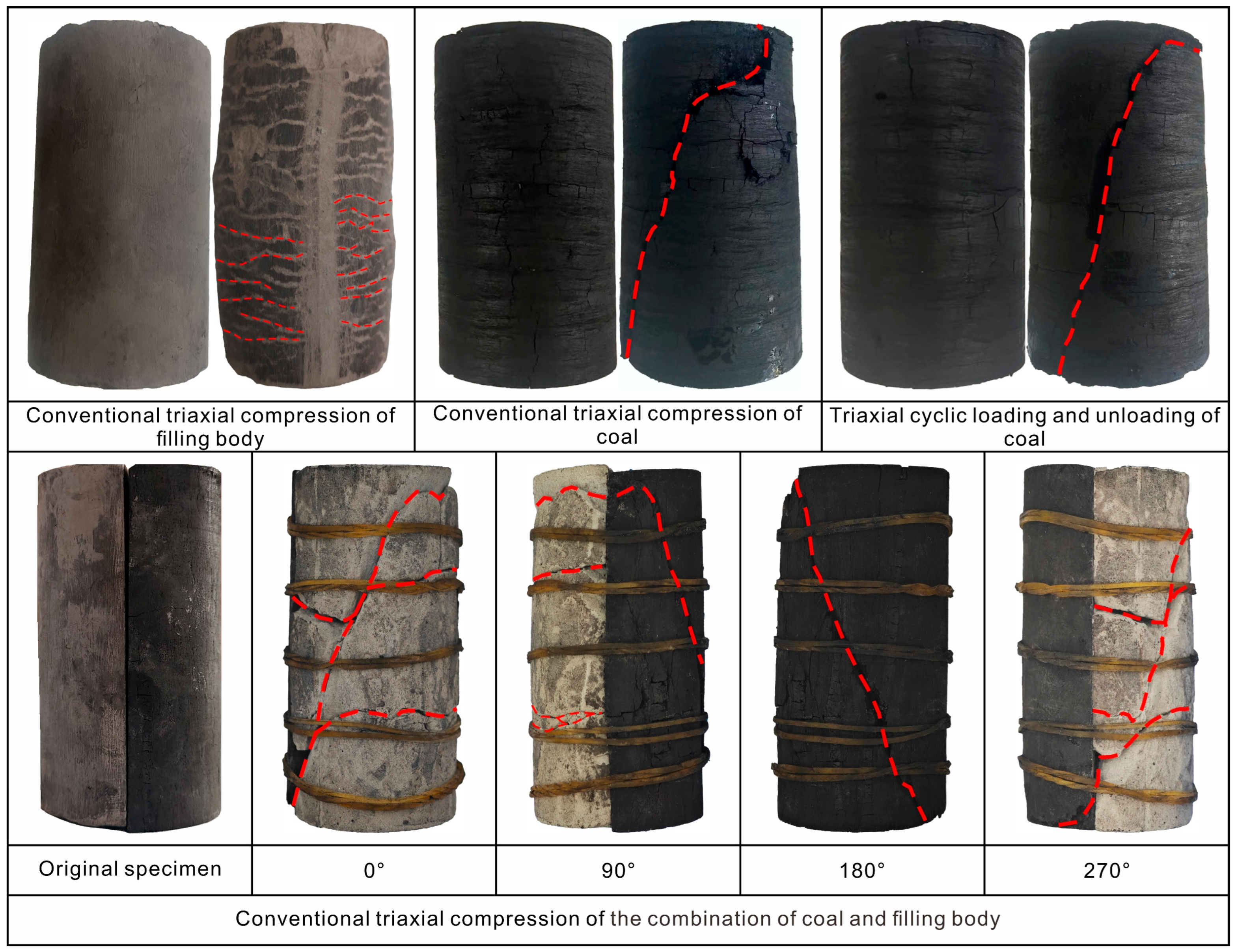
Figure 13 sequentially presents images of the specimens before and after conventional triaxial compression tests for the filling body, conventional triaxial compression tests for coal, triaxial cyclic loading-unloading tests for coal, and conventional triaxial compression tests for the combination of coal and filling body.
Figure 13.
Failure characteristics of specimens in triaxial compression test. The red dash line indicates the crack position of the specimen.
The images of the filling body before and after the conventional triaxial compression test indicate that after the test, the specimen’s surface exhibits radial fish-scale-like wrinkles. However no fully developed shear failure zone is observed—the specimen as a whole displays a bulging and dilative deformation characteristic.
The images of coal before and after the conventional triaxial compression test reveal that the specimen primarily undergoes shear failure [33,34,35], with a primary shear crack extending from the top to the bottom of the specimen. A small area of surface spalling is observed below the primary shear crack at the top. The fracture surface of the specimen is not fully penetrated and exhibits tensile markings at the fracture opening. Measurements show that the fracture surface angle ranges between 75° and 80°.
Based on the images of the specimens before and after the triaxial cyclic loading and unloading tests on coal, it can be observed that the failure mode of the specimens is characterized by shear failure along the joint planes, with relatively rough fracture surfaces. Compared to conventional triaxial compression tests on coal, the fracture surface angle of coal specimens under cyclic loading and unloading stress paths is more minor, ranging between 70° and 75°. According to Mohr-Coulomb theory, the fracture surface angle is positively correlated with the internal friction angle of the specimen material [36]. When the influence of internal weak planes within the specimen on the failure is disregarded, the reduction in fracture surface angle indicates a decrease in the internal friction angle, thereby reflecting that cyclic loading and unloading in the elastic region of coal weakens the internal friction angle, which is a critical aspect of the shear strength of the coal.
From the images of the specimens before and after the conventional triaxial compression tests on composite specimens, it is evident that the filling body side of the composite specimen (rotated to 0° along the axial direction) exhibits fish-scale-like folds similar to those observed in conventional triaxial compression tests of the filling body, although the folds are less pronounced. Additionally, a primary shear crack runs through the top and bottom of the filling body side, with secondary cracks distributed nearly perpendicular to the primary shear crack. On the coal side (rotated to 180° along the axial direction), there is a primary shear crack running through the top and bottom of the specimen, with minimal secondary cracking and surface spalling. At the interface between the filling material and coal (rotated to 90° and 270° along the axial direction), the primary shear crack generated on the filling body side connects with the primary shear crack on the coal side. In contrast, secondary cracks on the filling body side rarely penetrate the coal side.
The above analysis indicates that the dominant factor causing specimen failure in conventional triaxial compression tests of the filling body, conventional triaxial compression tests of coal, triaxial cyclic loading and unloading tests on coal, and conventional triaxial compression tests of the combination of coal and filling body specimens is the shear stress imbalance induced by deviatoric stress.
5.3.3. Mechanical Characteristics in the Loading Process
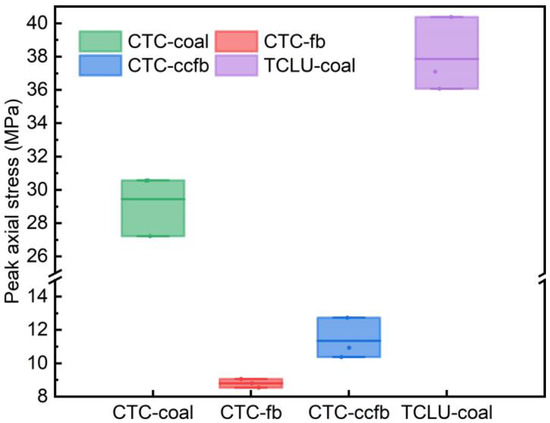
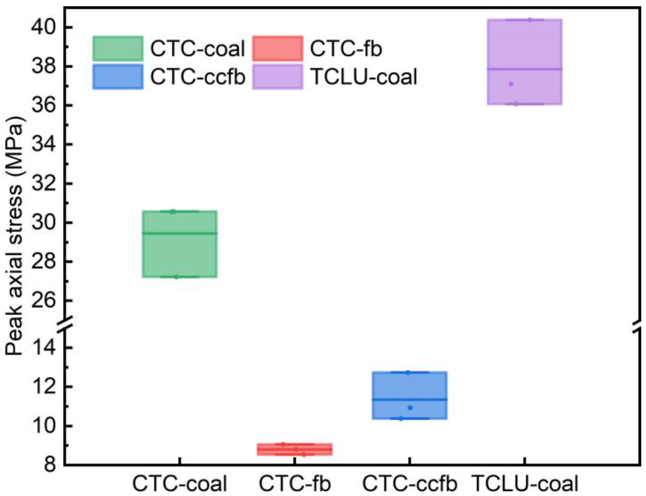
Figure 14 presents the peak axial stress results from conventional triaxial compression tests on coal, filling body, and the combination of coal and filling body, as well as from cyclic triaxial loading-unloading tests on coal. The lines in the box plot represent the mean peak stress values. According to Figure 14, the peak axial stresses from the conventional triaxial compression tests on coal are 30.55 MPa, 27.22 MPa, and 30.58 MPa, with an average peak axial stress of 29.45 MPa. For the filling body, the peak axial stresses are 8.53 MPa, 9.05 MPa, and 8.80 MPa, with an average peak axial stress of 8.79 MPa. The combination of coal and filling body exhibit peak axial stresses of 12.73 MPa, 10.37 MPa, and 10.93 MPa, with an average peak axial stress of 11.34 MPa. The peak axial stresses from the cyclic triaxial loading-unloading tests on coal are 40.38 MPa, 36.08 MPa, and 37.09 MPa, with an average peak axial stress of 37.85 MPa.
Figure 14.
Peak axial stress of triaxial compression test.
Comparing the peak axial stress results from the conventional triaxial compression tests on coal, filling body, and the combination of coal and filling body under a confining pressure of 2 MPa reveals that the peak axial stress of coal is greater than that of the filling body. The peak axial stress of the combination of coal and filling body lies between the peak axial stresses of coal and filling body but tends to be closer to the lower peak stress of the filling body. This indicates that under triaxial stress conditions, the load-bearing capacity of the system is primarily determined by the weaker load-bearing medium.
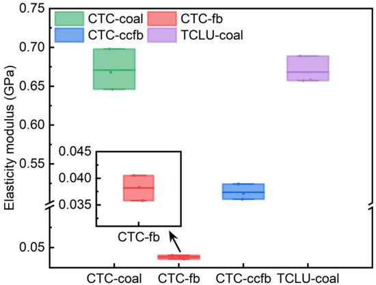
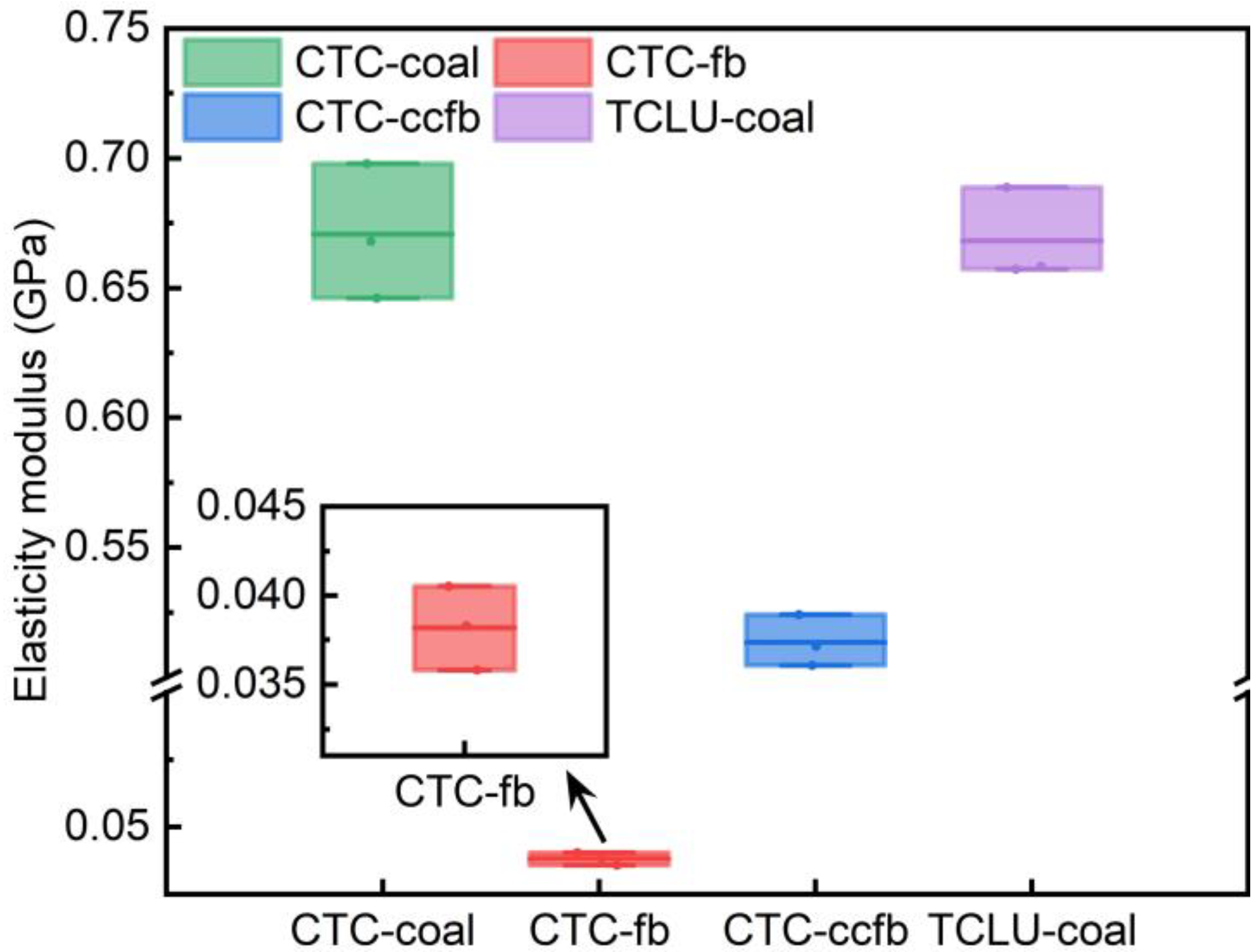
Figure 15 presents the elastic modulus test results from conventional triaxial compression tests on coal, filling body, and the combination of coal and filling body, as well as from triaxial cyclic loading-unloading tests on coal. The central line in the box plots represents the mean elastic modulus. According to Figure 15, the elastic modulus results for the conventional triaxial compression tests on coal were 698.0 MPa, 646.0 MPa, and 668.0 MPa, with an average elastic modulus of 670.7 MPa. For the filling body, the elastic modulus values were 35.8 MPa, 40.5 MPa, and 38.3 MPa, with an average of 38.2 MPa. The combination of coal and filling body showed elastic modulus values of 504.5 MPa, 524.1 MPa, and 511.9 MPa, with an average of 513.5 MPa. The triaxial cyclic loading-unloading tests on coal yielded elastic modulus values of 658.3 MPa, 657.3 MPa, and 688.7 MPa, with an average of 668.1 MPa.
Figure 15.
Elasticity modulus of triaxial compression test.
Comparison of the elastic modulus results from the conventional triaxial compression tests for coal, filling body, and the combination of coal and filling body reveals that under a confining pressure of 2 MPa, the elastic modulus decreases in the order of coal, composite, and filling body. The elastic modulus of the composite samples is slightly lower than that of coal but significantly higher than that of the filling body. This suggests that the composite’s resistance to elastic deformation is primarily influenced by the coal, which has a higher elastic modulus. In contrast, the filling body, with its lower elastic modulus, weakens the composite’s overall resistance to elastic deformation. Additionally, comparing the elastic modulus from conventional triaxial compression tests and triaxial cyclic loading-unloading tests on coal indicates that the cyclic loading-unloading process within the elastic region has a negligible effect on modifying the coal’s elastic modulus. The coal’s resistance to elastic deformation under both testing conditions is similar.
6. Conclusions
This study focused on the continuous mining and continuous backfilling (CMCB) in close distance coal seams. It developed a mechanical load-bearing model for the continuous mining and continuous backfilling support unit (CMCBSU). The complex stress paths of CMCBSU in close distance coal seams were analyzed using numerical simulation methods. Subsequently, conventional triaxial compression tests on coal, filling body, and the combination of coal and filling body, as well as triaxial cyclic loading and unloading tests on coal, were conducted to elucidate the collaborative load-bearing mechanism of the CMCBSU. The main findings of the study are as follows:
1. A mechanical load-bearing model for CMCBSU was derived. Based on Wilson’s progressive failure theory, the model revealed that the load borne by the CMCBSU is influenced by factors such as the elastic modulus of the coal pillar and filling body, coal seam depth, and roadway width. It was found that the greater the similarity in elastic modulus between the coal pillar and the filling body, the more stable the surrounding rock. Under conditions where the elastic moduli of the coal and filling body are identical, an increase in roadway width, overburden density, and mining depth leads to an increase in both the load and deformation of the CMCBSU. Therefore, during the design phase of CMCB, efforts should be made to ensure mechanical similarity between the filling body and coal pillars while also considering the reduction in roadway width to optimize surface subsidence control.
2. CMCB in close distance coal seams exerts a cyclic loading and unloading effect on residual coal pillars. The CMCB process in the upper seam impacts the unmined coal pillars in the lower seam through cyclic loading and unloading, with the number of cycles corresponding to the number of roadways within the CMCBSU. Additionally, the advanced stress generated by roadways undergoing CMCB in the same coal seam affects coal pillars that have yet to undergo the CMCB process.
3. The study elucidates the characteristics of the deviatoric stress–strain curves of the combination of coal and filling body under triaxial compression conditions. The coal exhibited significant brittleness during conventional triaxial compression tests. In contrast, the filling body demonstrated pronounced strain-softening behavior, accompanied by rapid radial expansion and a slight rebound in axial deformation prior to failure. The composite specimen also displayed strain-softening behavior under conventional triaxial compression conditions. Additionally, the cyclic loading and unloading tests on the coal under triaxial conditions revealed the presence of hysteresis loops within the elastic region.
4. Furthermore, the study reveals the failure characteristics of the composite specimen under triaxial compression. The shear stress imbalance induced by deviatoric stress is identified as the primary cause of failure in the coal, filling body, and composite specimen. When disregarding the influence of internal weak planes on specimen failure, it was observed that the cyclic loading and unloading within the elastic region of the lower coal seam, caused by the upper coal seam in close distance coal seams, weakens the internal friction angle, one of the shear resistance properties of the coal. After the tests, the filling body exhibited radial fish-scale-like folds on the specimen surface. In contrast, the coal and composite specimens showed primary shear cracks extending through the top and bottom of the specimens. In the composite specimens, secondary cracks nearly perpendicular to the primary shear crack were observed on the filling body side. In contrast, the coal side showed minimal secondary cracking or surface spalling. At the interface between the filling body and the coal in the composite specimens, the primary shear crack generated on the backfill side penetrated the coal side. However, the secondary cracks on the filling body side rarely extended into the coal side.
5. Finally, the mechanical characteristics of the composite specimen composed of coal and filling body under triaxial compression conditions were revealed. The results of peak axial stress indicate that, under triaxial stress conditions, the load-bearing capacity of the CMCBSU is primarily determined by the weaker load-bearing medium. The elastic modulus test results demonstrate that the resistance to elastic deformation of the composite specimen mainly depends on the coal, which has a higher elastic modulus. The filling body, with a lower elastic modulus, weakens the composite’s resistance to elastic deformation. A comparison between the conventional triaxial compression tests and triaxial cyclic loading-unloading tests on coal shows that the cyclic loading and unloading induced by CMCB in close distance coal seams has negligible impact on the coal’s resistance to elastic deformation.
6. In addition, it should be emphasized that the mechanical behavior revealed in this study is inherently characteristic of Close Distance Coal Seams (CDCS). The sequential excavation and backfilling in the upper and lower seams generate superimposed stress fields and induce interlayer bending effects, which together intensify the stress fluctuations acting on the CMCBSU. These multi-seam interactions are responsible for the cyclic stress paths and amplified loading responses identified in both the numerical simulations and laboratory tests. If the coal seams were not closely spaced, or if only a single seam were present, the CMCBSU would be subjected solely to the overburden load of one seam, resulting in a simpler and more monotonic stress evolution. Therefore, the conclusions drawn in this work should be understood as applicable to CDCS environments, where the multi-seam coupling effect plays a dominant role in governing the stability of the CMCBSU.
7. Prospects
Although this study provides new insights into the mechanical behavior of CMCBSU in close-distance coal seams, several aspects require further investigation:
1. The present work does not consider the time-dependent development of filling-body strength during the 28-day curing period. Future studies should incorporate the evolution of filling-body stiffness and the corresponding roadway deformation to more accurately reflect stope stability during early filling stages.
2. The CMCB process in close-distance seams induces variable-amplitude cyclic loading on the lower seam. The effects of CMCB layout, interlayer spacing, and roadway arrangement on the amplitude and frequency of these stress disturbances should be analyzed to refine mechanical models of coal pillar deterioration.
3. In the cyclic loading–unloading tests, the final-stage confining pressure differed from that in conventional triaxial tests, preventing a direct comparison of peak strength parameters. Future work should employ identical final confining pressures to clarify the influence of cyclic loading on coal strength parameters.
4. This study assumes no fluid or chemical exchange between the coal and filling material due to the presence of a plastic isolation sheet. However, in field operations, imperfect sealing may allow water or ions to migrate at the coal–filling interface. Future experiments should directly cast backfill slurry against split coal specimens to evaluate the mechanical effects of interfacial substance exchange.
5. The monitoring methods in this study could not capture real-time crack evolution or internal damage development. Advanced techniques such as acoustic emission (AE), CT scanning, and digital image correlation (DIC) should be integrated into future triaxial testing to visualize failure processes and improve understanding of CMCBSU damage mechanisms. Such insights will support the development of optimized reinforcement strategies for CMCB operations.
Author Contributions
Conceptualization, G.Z.; methodology, H.W.; software, H.W.; validation, H.W. and J.Z.; formal analysis, H.W.; investigation, H.W. and J.Z.; resources, G.Z.; writing—original draft preparation, G.Z. and H.W.; writing—review and editing, G.Z.; visualization, H.W.; supervision, G.Z.; funding acquisition, G.Z. All authors have read and agreed to the published version of the manuscript.
Funding
This research was funded by Basic Research Foundation of Shanxi Province, China (Grant No. 202303021221007), National Natural Science Foundation of China (Grant No. U22A20167) and National Engineering Research Center for Coal Mine Backfill Mining Innovation Project of Shandong Energy Group (Grant No. SDEGIF-CT202503).
Data Availability Statement
The data presented in this study are available on request from the corresponding author due to confidential information.
Conflicts of Interest
The authors declare no conflicts of interest.
Abbreviations
The following abbreviations are used in this manuscript:
| CMCB | Continuous mining and continuous backfilling |
| CMCBSU | continuous mining and continuous backfilling |
References
- Energy Institute. Statistical Review of World Energy. Available online: https://www.energyinst.org/statistical-review (accessed on 5 September 2024).
- Zhou, N.; Yao, Y.N.; Song, W.J.; He, Z.W.; Meng, G.H.; Liu, Y. Present situation and prospect of coal gangue treatment technology. J. Min. Saf. Eng. 2020, 37, 136–146. [Google Scholar] [CrossRef]
- Wang, J.C.; Yang, Z.B.; Qin, Y.; Yang, Y.Q.; Dong, Z.Y.; Meng, X.H. Research status and prospects of secondary enrichment and accumulation of residual coalbed methane resources in abandoned mines. Coal Geol. Explor. 2022, 50, 35–44. [Google Scholar] [CrossRef]
- Yuan, L.; Zhang, T.; Zhang, Q.H.; Jiang, B.Y.; Lyu, X.; Li, S.S.; Fu, Q. Construction of green, low-carbon and multi-energy complementary system for abandoned mines under global carbon neutrality. J. China Coal Soc. 2022, 47, 2131–2139. [Google Scholar] [CrossRef]
- Yuan, L.; Jiang, Y.D.; Wang, K.; Zhao, Y.X.; Hao, X.J.; Xu, C. Precision exploitation and utilization of closed/abandoned mine resources in China. J. China Coal Soc. 2018, 43, 14–20. [Google Scholar] [CrossRef]
- Hu, Z.Q.; Fu, Y.H.; Xiao, W.; Zhao, Y.L.; Wei, T.T. Ecological restoration plan for abandoned underground coal mine site in Eastern China. Int. J. Min. Reclam. Environ. 2015, 29, 316–330. [Google Scholar] [CrossRef] [Scilit]
- Lyu, X.; Yang, K.; Fang, J.J. Utilization of resources in abandoned coal mines for carbon neutrality. Sci. Total Environ. 2022, 822, 153646. [Google Scholar] [CrossRef] [Scilit]
- Feng, D.L.; Wang, J.; Wang, Y.X.; Xiao, X.L.; Hou, W.J.; Liang, S.H. Alkali-activated geopolymer materials prepared from coal gangue and municipal solid waste incineration byproducts. J. Build. Eng. 2023, 80, 108074. [Google Scholar] [CrossRef] [Scilit]
- Li, J.Y.; Wang, J.M. Comprehensive utilization and environmental risks of coal gangue: A review. J. Clean. Prod. 2019, 239, 117946. [Google Scholar] [CrossRef] [Scilit]
- Yao, Z.T.; Ji, X.S.; Sarker, P.K.; Tang, J.H.; Ge, L.Q.; Xia, M.S.; Xi, Y.Q. A comprehensive review on the applications of coal fly ash. Earth-Sci. Rev. 2015, 141, 105–121. [Google Scholar] [CrossRef] [Scilit]
- Han, F.L.; Wu, L.E. Comprehensive utilization of fly ash. In Industrial Solid Waste Recycling in Western China; Springer: Singapore, 2019; pp. 207–304. [Google Scholar] [CrossRef] [Scilit]
- Huang, D.M.; Xing, D.Q.; Chang, X.K.; Zhu, Y.Y.; Gao, C.J. Analysis and application of filling mining technology in China’s mining area: A case study of Yuxing Coal Mine. Arch. Min. Sci. 2021, 66, 611–624. [Google Scholar] [CrossRef] [Scilit]
- Lu, B.; Li, Y.L.; Fang, S.Z.; Lin, H.; Zhu, Y. Cemented backfilling mining technology for gently inclined coal seams using a continuous mining and continuous backfilling method. Shock. Vib. 2021, 2021, 6652309. [Google Scholar] [CrossRef] [Scilit]
- Lin, H.; Yang, R.S.; Lu, B.; Li, Y.L.; Fang, S.Z.; Fan, Z.Y.; Li, Z.Z. Overlying strata movement law of continuous mining and continuous backfilling cemented-fill mining. Environ. Earth Sci. 2021, 80, 688. [Google Scholar] [CrossRef] [Scilit]
- Shi, X.H.; Lu, B.; Lin, H. Application of continuous mining and continuous backfilling cementfill technology in Haoyuan Coal Mine. Coal Technol. 2022, 41, 42–46. [Google Scholar] [CrossRef]
- Lin, H.; Yang, R.S.; Li, Y.L.; Fang, S.Z. Stability of coal pillar and roof movement characteristics in roadway backfill mining. Adv. Civ. Eng. 2021, 2021, 5588923. [Google Scholar] [CrossRef] [Scilit]
- Li, Y.L.; Lu, B.; Yang, R.S.; Lin, H.; Xu, B.; Wang, S.S.; Liu, C.H. Cemented backfilling mining technology with continuous mining and continuous backfilling method for underground coal mine and typical engineering cases. J. China Coal Soc. 2022, 47, 1055–1071. [Google Scholar] [CrossRef]
- Dong, L.J.; Zhang, Y.H.; Chen, Z.J.; Kou, Y.Y.; Pei, Z.W. Dynamic stress characterization and instability risk identification using multisource acoustic signals in cut-and-fill stopes. Sci. Rep. 2024, 14, 16499. [Google Scholar] [CrossRef] [Scilit]
- Li, Y.; Wang, N.; Lei, X.H.; Li, T.Z.; Ren, Y.Q.; Jin, X.Y. Stress evolution of repeated mining based on the double-yield model in multiple coal seam. Rock Mech. Rock Eng. 2024, 57, 2809–2827. [Google Scholar] [CrossRef] [Scilit]
- Meng, Z.; Dong, Y.; Zhang, X.; Jiao, F.; Fan, Y.; Thammavongsa, C. Short-Wall Paste Continuous Mining and Continuous Backfilling for Controlling Industrial Square Surface Subsidence. Front. Earth Sci. 2023, 10, 1009617. [Google Scholar] [CrossRef] [Scilit]
- Chen, D.; Wang, X.; Bai, J.; Zhang, F. Deformation Mechanism and Control Technology of Gob-Side Roadway with Continuous Mining and Continuous Backfilling: A Case Study. Geomat. Nat. Hazards Risk 2024, 15, 2350480. [Google Scholar] [CrossRef] [Scilit]
- Wang, S.K. Evolution Laws of Filing Body Creep and Overlying Strata Permeability by Using Continuous Excavation and Continuous Backfilling. Ph.D. Thesis, China University of Mining and Technology, Beijing, China, 2021. [Google Scholar] [CrossRef]
- Zhu, W.H.; Wang, F.; Chen, S.J.; Yin, D.W.; Zhou, J.K.; Jie, Z.Q.; Zou, Y.L. Asymmetric deformation mechanism of roadway with continuous mining and continuous backfilling. Rock Mech. Rock Eng. 2024, 57, 2125–2142. [Google Scholar] [CrossRef] [Scilit]
- Xu, B.; Li, Y.L.; Wang, S.S.; Luo, H.H.; Lu, B. Study on the strength characteristics and failure characteristics of the composite load-bearing structure in the cemented filling field. Constr. Build. Mater. 2022, 330, 127242. [Google Scholar] [CrossRef] [Scilit]
- Sakhno, I.; Sakhno, S.; Vovna, O. Assessing a Risk of Roof Fall in the Development Mine Workings in the Process of Longwall Coal Mining. Min. Miner. Depos. 2020, 14, 72–80. [Google Scholar] [CrossRef] [Scilit]
- Martin, C.D.; Chandler, N.A. The progressive fracture of Lac du Bonnet granite. Int. J. Rock Mech. Min. Sci. Geomech. Abstr. 1994, 31, 643–659. [Google Scholar] [CrossRef] [Scilit]
- Liu, W.L.; Yan, E.C.; Dai, H.; Du, Y.; Xiao, W.B.; Zhao, S. Study on characteristic strength and energy evolution law of Badong formation mudstone under water effect. Chin. J. Rock Mech. Eng. 2020, 39, 311–326. [Google Scholar] [CrossRef]
- Xiao, Y.M.; Qiao, Y.F.; He, M.C.; Li, A.G. Strain rate effect of siltstone under triaxial compression and its interpretation from damage mechanics. Rock Mech. Rock Eng. 2023, 56, 8643–8656. [Google Scholar] [CrossRef] [Scilit]
- Hao, Q.J.; Zhang, R.; Gao, M.Z.; Xie, J.; Ren, L.; Zhang, A.L.; Wang, M.N.; Zhang, Z.T. Characterization of energy-driven damage mechanism and gas seepage in coal under mining-induced stress conditions. Int. J. Rock Mech. Min. Sci. 2024, 181, 105834. [Google Scholar] [CrossRef] [Scilit]
- Wanatowski, D.; Chu, J.; Lo, R.S.C. Strain-softening behaviour of sand in strain path testing under plane-strain conditions. Acta Geotech. 2008, 3, 99–114. [Google Scholar] [CrossRef] [Scilit]
- Ding, Z.W.; Jia, J.D.; Tang, Q.B.; Li, X.F. Mechanical properties and energy damage evolution characteristics of coal under cyclic loading and unloading. Rock Mech. Rock Eng. 2022, 55, 4765–4781. [Google Scholar] [CrossRef] [Scilit]
- Chen, Y.; Wang, G.F.; Zhou, L.; Zhang, G.L.; Yang, J.F.; Li, M.H. Effect of cyclic loading and unloading on the deformation and damage properties of sandstone from Beizao, a Coal Mine underneath the Bohai Sea in China. Geofluids 2022, 2022, 9654025. [Google Scholar] [CrossRef] [Scilit]
- Yang, S.Q.; Jing, H.W. Strength failure and crack coalescence behavior of brittle sandstone samples containing a single fissure under uniaxial compression. Int. J. Fract. 2011, 168, 227–250. [Google Scholar] [CrossRef] [Scilit]
- Pan, P.Z.; Ding, W.X.; Feng, X.T.; Yao, H.Y.; Zhou, H. Research on influence of pre-existing crack geometrical and material properties on crack propagation in rocks. Chin. J. Rock Mech. Eng. 2008, 27, 1882–1889. [Google Scholar] [CrossRef]
- Bobet, A. The initiation of secondary cracks in compression. Eng. Fract. Mech. 2000, 66, 187–219. [Google Scholar] [CrossRef] [Scilit]
- Yang, S.Q.; Jiang, Y.Z.; Xu, W.Y.; Chen, X.Q. Experimental investigation on strength and failure behavior of pre-cracked marble under conventional triaxial compression. Int. J. Solids Struct. 2008, 45, 4796–4819. [Google Scholar] [CrossRef] [Scilit]

Disclaimer/Publisher’s Note: The statements, opinions and data contained in all publications are solely those of the individual author(s) and contributor(s) and not of MDPI and/or the editor(s). MDPI and/or the editor(s) disclaim responsibility for any injury to people or property resulting from any ideas, methods, instructions or products referred to in the content. |
© 2025 by the authors. Licensee MDPI, Basel, Switzerland. This article is an open access article distributed under the terms and conditions of the Creative Commons Attribution (CC BY) license (https://creativecommons.org/licenses/by/4.0/).