


Abstract
A guide vane was installed on a heat sink to enhance the cooling effect of light-emitting diode (LED) lights. The validity of the numerical analysis was verified against the experimental results and the result of the previous studies. The effect of the guide vane on the heat dissipation performance of the heat sink was identified. The effect of the guide vane on the heat sink was qualitatively studied using the streamline and temperature contour. The cooling effect of the heat sink was enhanced by increased air supplement to the center-bottom part. A parametric study was conducted to determine the thermal resistance according to the guide vane angle, installation height, and vane length. Optimization was performed to minimize the thermal resistance using the Kriging model and micro-genetic algorithm (MGA). The cooling performance of the heat sink was enhanced by a maximum of 17.2% when the guide vane was installed.
1. Introduction
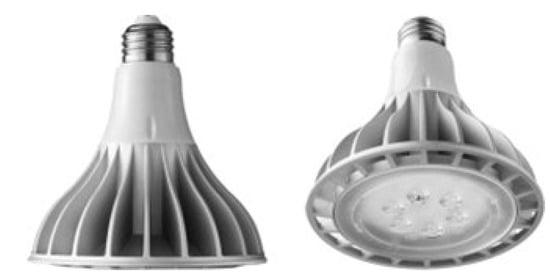
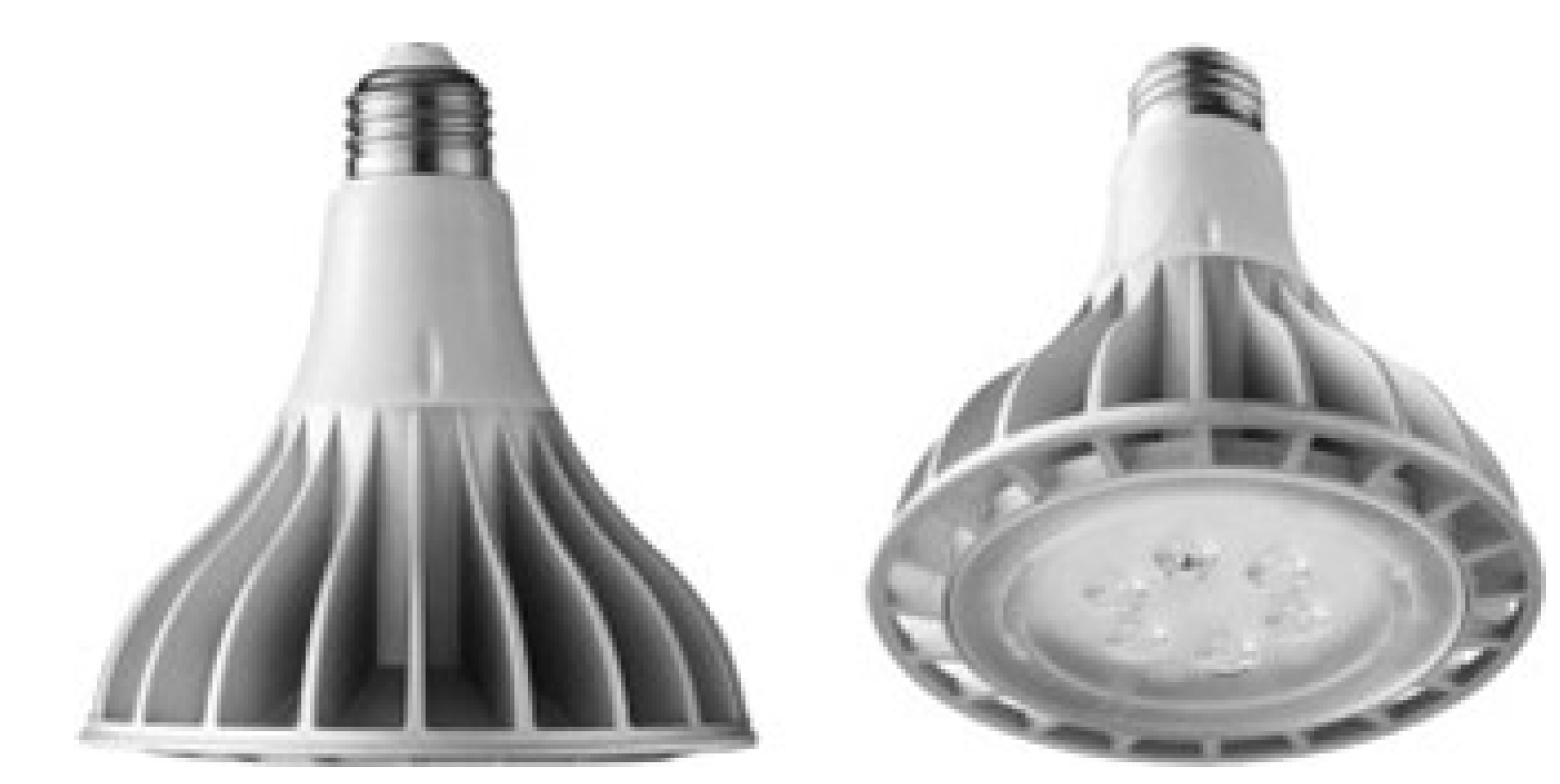
As the lifespan and luminous efficiency of light-emitting diode (LED) lights increase [1,2], research is being conducted to solve the overheating problem [3]. Since the temperature increase due to the heat generation of LED lights is directly related to the life of the LED, research to solve this problem is essential [4,5,6]. Figure 1 shows a typical heat sink installed for heat dissipation of LED lights. Increasing the size of the heat sink not only increases the cost but also increases the weight, requiring a systematic heat sink design. Although studies on various heat sink designs such as geometry modification have been carried out [7,8,9], these studies are structurally complex and increase cost burden due to the complicated manufacturing process. In consideration of these points, there is a limitation in improving the cooling effect by only modifying the shape of a heat sink.
Figure 1.
Conventional LED heat sink.
Experimental studies have been performed to improve the cooling effect of a heat sink. Bai et al. [10] conducted an experimental study on the heat sink with heat pipe for automotive LED lights. Mo et al. [11] studied the cooling effect of LED by a thermoelectric cooler with a microchannel heat sink. Wang et al. [12] investigated the cooling effect of LED heat sinks with the oscillating heat pipes. Lu et al. [13] analyzed a efficiency of LED package consisting of heat pipe heat sinks. Alvin et al. [14] experimentally investigated the extruded aluminum fin heat sink for LED cooling. Khatamifar et al. [15] studied the geometry effect on additive manufactured aluminum LED heat sinks.
Studies have been conducted numerically to enhance the cooling effect of a heat sink. Lin et al. [11] conducted a Taguchi analysis on the cooling of the LED heat sink by a thermoelectric cooler. Mey et al. [16] conducted research on the chimney effect on the cooling of a transistor mounted on a cooling fin under natural convection. Silva et al. [17] presented optimal geometry of L and C-shaped channels for maximum heat transfer. Shimoyama et al. [18] estimated the thermal characteristics of an upward-facing heated surface with a cylindrical pipe. Park et al. [19] have suggested installing a hollow cylinder for downlights heat sinks. Souayeh et al. [20] investigated the magnetic dipole flow over a stretching sheet in the presence of a non-uniform heat source/sink. Li et al. [21] proposed an enhanced design of a heatsink with a chimney operating under natural convections. However, most of these studies are difficult to directly apply to radial heat sinks due to the increase in the size and mass of a heat sink or the complicity of the manufacturing process.
In this study, a guide vane was installed on a heat sink to improve the thermal performance of the cooling system. Numerical analysis was conducted to identify the thermal and flow characteristics of the system. The numerical results were validated against the experimental results and the results of the previous studies. A parametric study was conducted to quantitatively investigate the effect of the guide vane on the cooling efficiency. Optimization was performed to minimize thermal resistance using the kriging model and micro-genetic algorithm (MGA).
2. Numerical Modeling
2.1. Mathematical Model
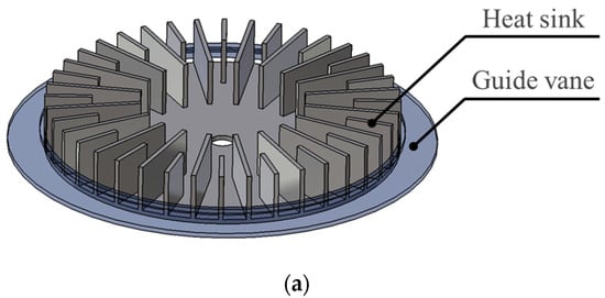
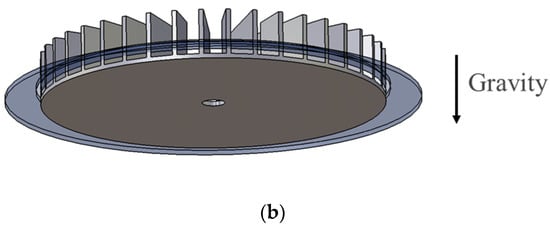
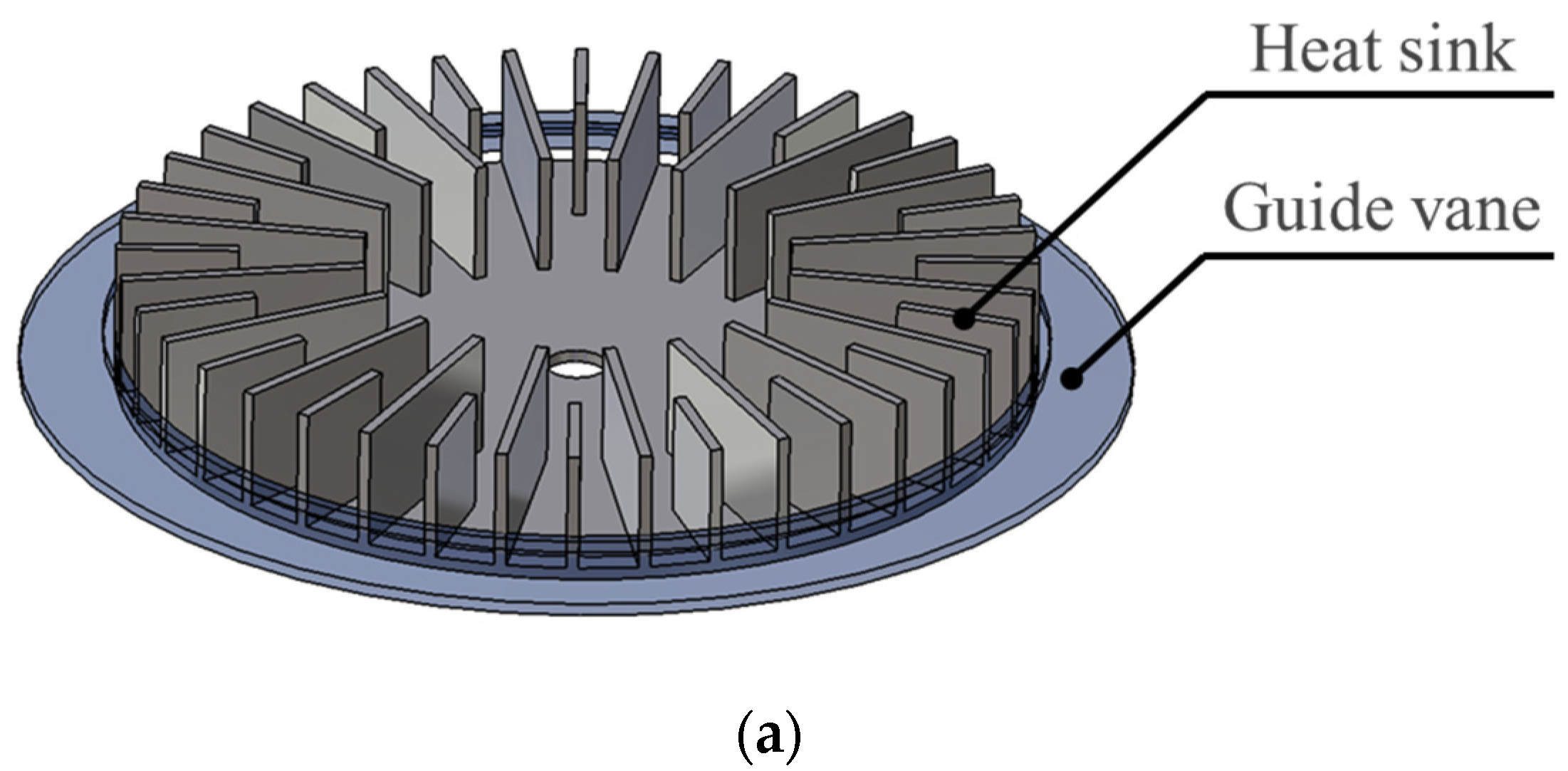
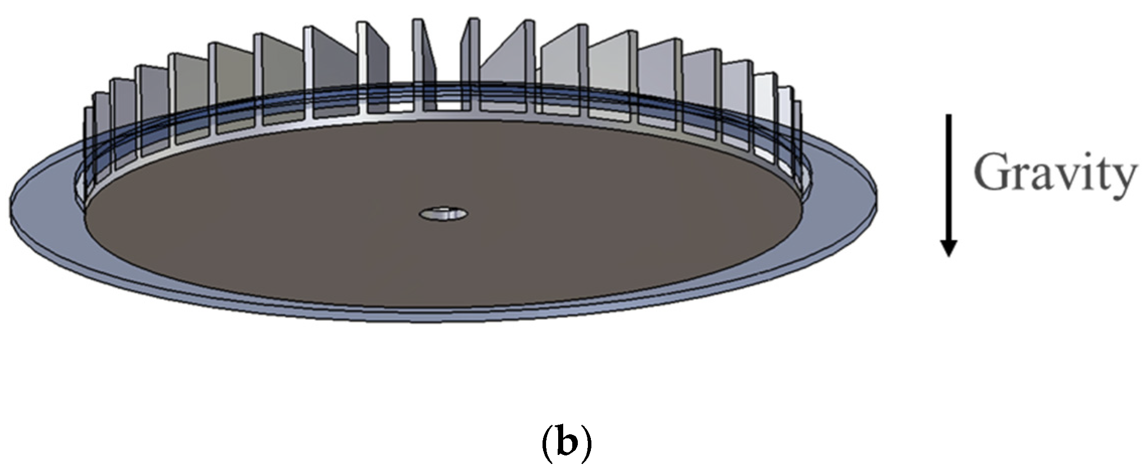
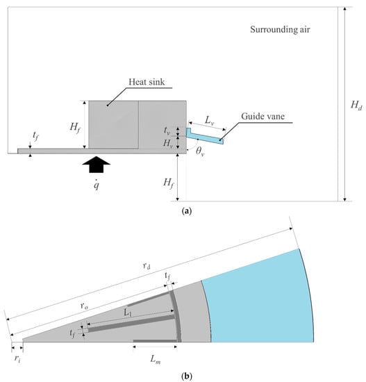
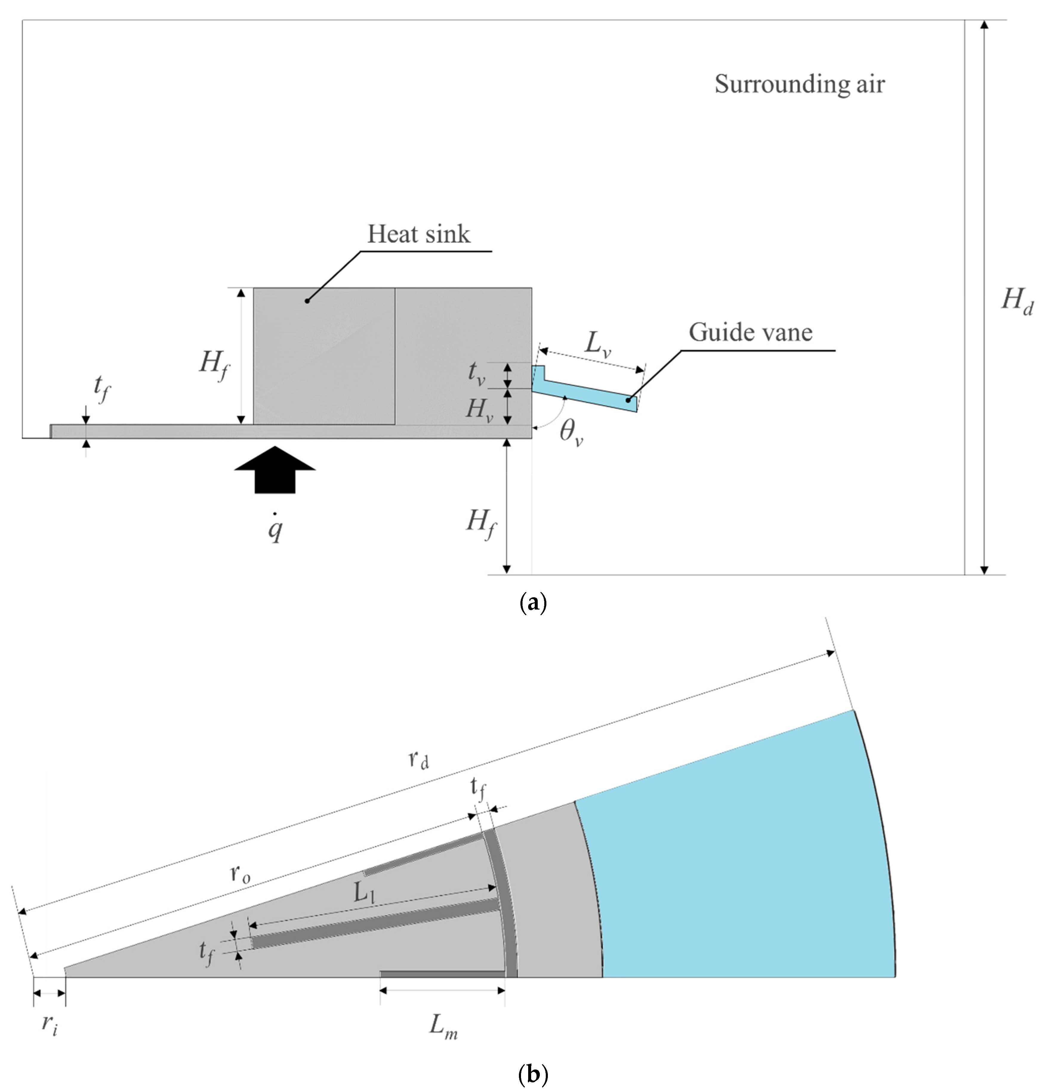
The schematic of the heat sink and guide vane is shown in Figure 2. The heat sink consists of two different length fins regularly arranged on the base. The computational domain is composed of a heat sink, guide vane, and surrounding air as shown in Figure 3a. The heat flux is uniformly supplied from the bottom of the heat sink. The periodic condition was applied since the fins on the radial heat sink repeat rotationally, as shown in Figure 3b. The computational burden was reduced by analyzing only the single-period domain (1/20 model). The boundary conditions of the numerical analysis are shown in Table 1.
Figure 2.
Schematic of a heatsink with a guide vane. (a) Isometric view 1; (b) isometric view 2.
Figure 3.
Computational domain. (a) Side view; (b) top view.
Table 1.
Boundary conditions for the numerical analysis [24].
The heat sink operates under natural convection conditions, and the assumptions of the numerical analysis are as follows:
- (1)
- The air is incompressible ideal gas.
- (2)
- The air properties are constant except for the density.
- (3)
- The flow is steady state.
The results of various numerical models were compared with the experimental results to find an appropriate turbulence model (Table 2). As compared in the table, it was the renormalization group (RNG) k-ε model that had the least error [22,23]. Accordingly, the numerical analysis was conducted using the (RNG) k-ε model.
Table 2.
Numerical model selection (Ts = 293 K, = 800 W/m2).
The governing equations for the continuity, energy, and momentum are as follows [19]:
In the Equation (1), is a coefficient of diffusion, is a source term, and is an arbitrary scalar, and they are summarized in Table 3. The definition of Gk, Sk, , , are as follows [19]:
Table 3.
Conservation laws components [24].
2.2. Numerical Procedure
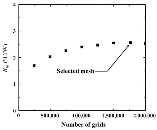
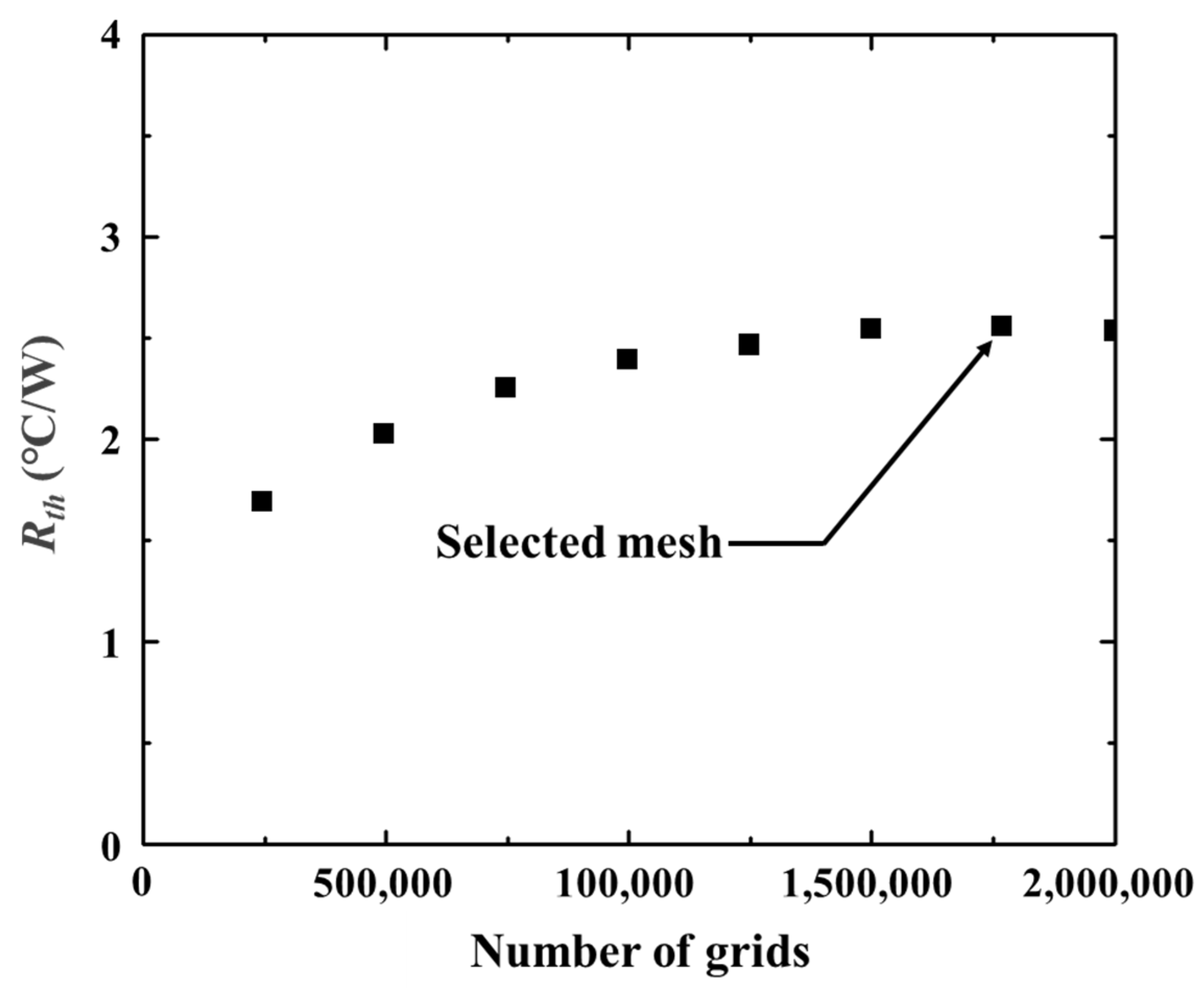
ANSYS Fluent 20202 R2 was used as a tool to carry out the numerical analysis. The SIMPLE algorithm was utilized to link the pressure and velocity, and the relative errors of all variables were set to less than 10−6 for convergence of the numerical results. Figure 3 shows the geometry of the cooling system. The dimensions of the parameters for the heat sink are , , , , , . In order to estimate the effect of the computational domain size on the flow and temperature, it was evaluated by changing the height Hd, and the radius of the domain (Figure 3). When the height Hd of the domain is five times the height of the heat sink Hf and the radius rd is twice the radius ro of the heat sink, it was confirmed that the numerical results changed by 0.4%, and this value was set as the domain size. To check the grid dependency, the numerical analysis was performed while modifying the grid number from 200,000 to 2,000,000 (Figure 4) [25]. As a result, when the number of grids was 1,823,490, the change of thermal characteristics was lower than 0.4%, and this was set as the reference [26].
Figure 4.
Thermal resistance in different number of meshes [27].
3. Experiments and Validation
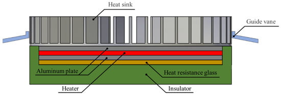
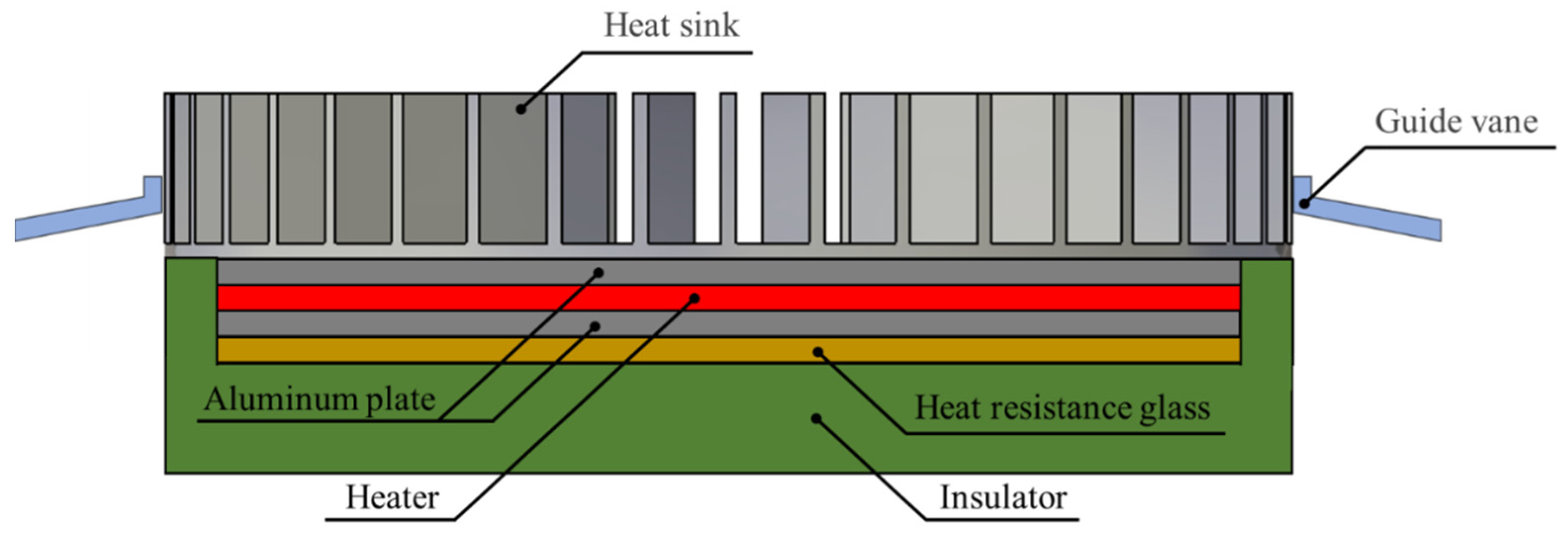
Figure 5 shows the experimental setup consisting of a heat sink, guide vane, aluminum plates, heater, heat resistance glass, and insulator. The heat sink consists of aluminum 6061 ( W/m°C), and the emissivity is . The dimensions of the parameters for the heat sink are , ,, , , . The guide vane is manufactured of acrylic with thermal conductivity of W/m°C. The range of the parameters for the guide vane are , , . A radial plate heater was installed to supply a heat flux to the heat sink uniformly, and the power was controlled using a transformer. An aluminum plate of 2 mm thickness was inserted between the heat sink and the heater so that the heat flux is uniformly transferred.
Figure 5.
Experimental setup.
A heat resistance glass with a thermal conductivity of W/m°C was used to measure the heat flux transferred to the bottom of the heater, and the temperature above and below the glass was measured and calculated as follows.
The heat flux delivered to the heat sink base was calculated by the difference between the input heat flux and the heat resistance glass as follows.
Heat loss was minimized by installing an insulator, and thermal grease was applied to all interfaces to minimize thermal resistance between solids. To measure the temperature of the heat sink, thermocouples were installed evenly on the heat sink base, long fin, and middle fin each. When the experiment was in a steady state, the temperature was recorded, and the temperature variation was less than 0.1 °C. Each experiment was conducted five times to secure a liability of 95% [28]. Thermal resistance was used as an index to determine the cooling effect, and the equation is as follows.
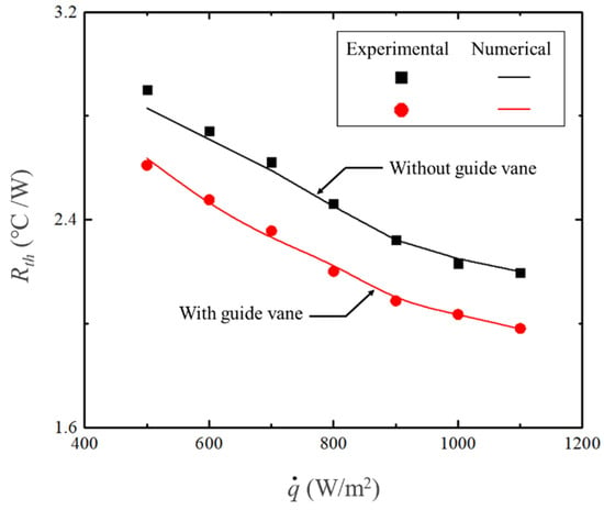
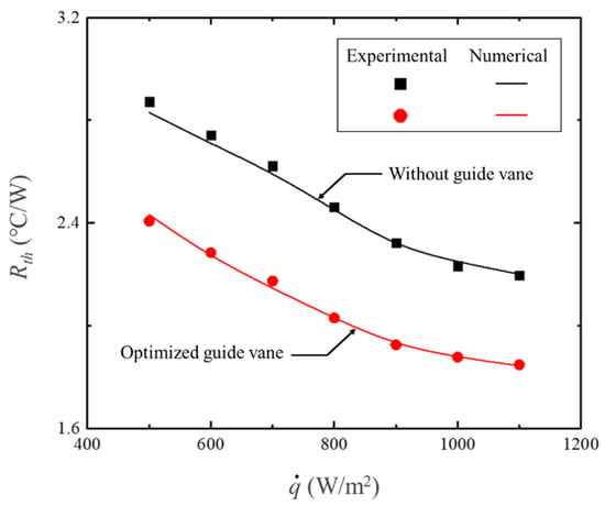
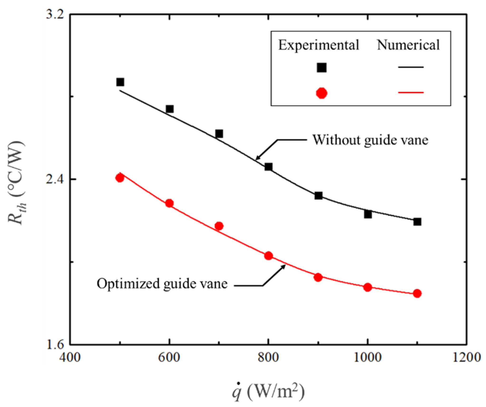
The thermal resistance according to the heat flux was shown in Figure 6. It was confirmed that the numerical results obtained using the RNG k-ε model were in good agreement with the experimental results within 2% of the maximum error (Table 2). In addition, the model was validated against the previous experimental results as shown in Table 4. The results show that the maximum error of the thermal resistance was 5.4%.
Figure 6.
Comparison of the thermal resistance with and without a guide vane.
Table 4.
Comparison with the previous studies.
4. Results and Discussion
In this section, the effect of the guide vane on the cooling effect of the heat sink was quantitatively studied. The heat resistance was used to determine the performance of the heat sink, and the influence of the guide vane on the cooling performance was identified through flow analysis. Optimization was performed to minimize thermal resistance using the Kriging model and micro-genetic algorithm (MGA).
4.1. Effect of Guide Vane
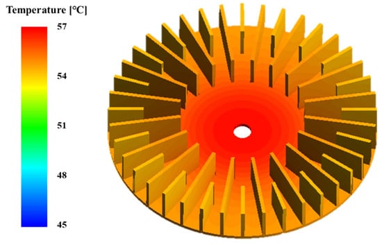
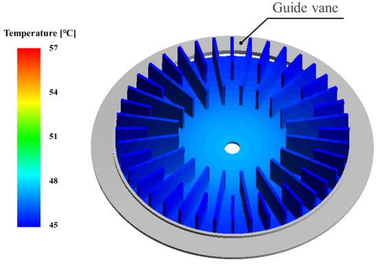
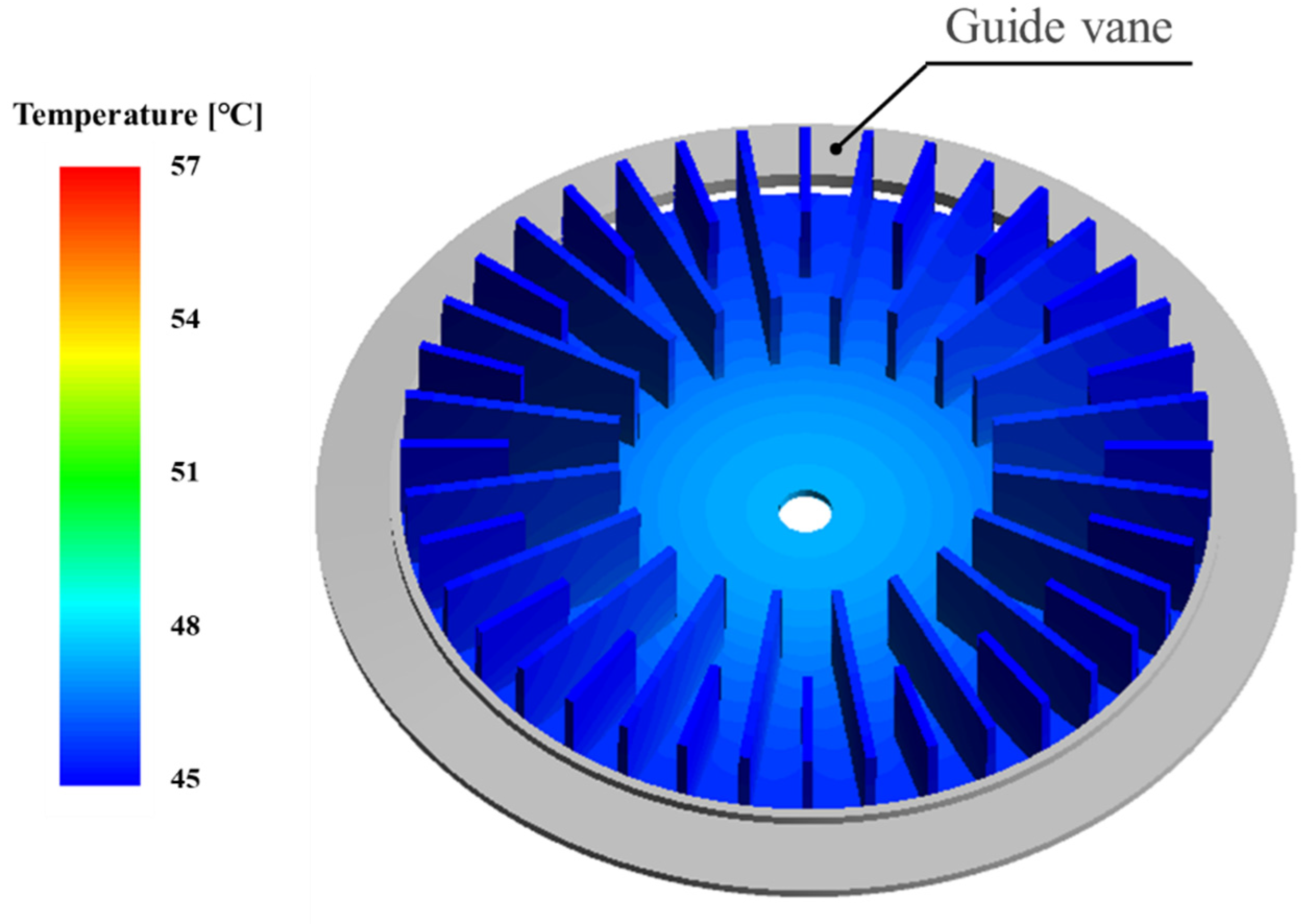
In order to determine the temperature distribution of the heat sink, the temperature contour was shown in Figure 7. As shown in the figure, the temperature is relatively high at the center-bottom of the heat sink. The air does not flow deep into the center of the heat sink causing heat concentration. Therefore, it is important to cool the center part of the heat sink, and the guide vane can facilitate the centripetal flow.
Figure 7.
Temperature contours of a heat sink (Ts = 20 °C, = 800 W/m2).
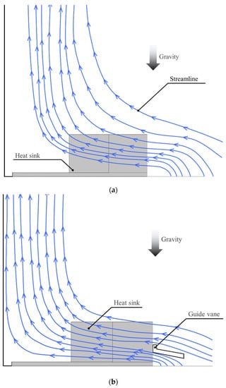
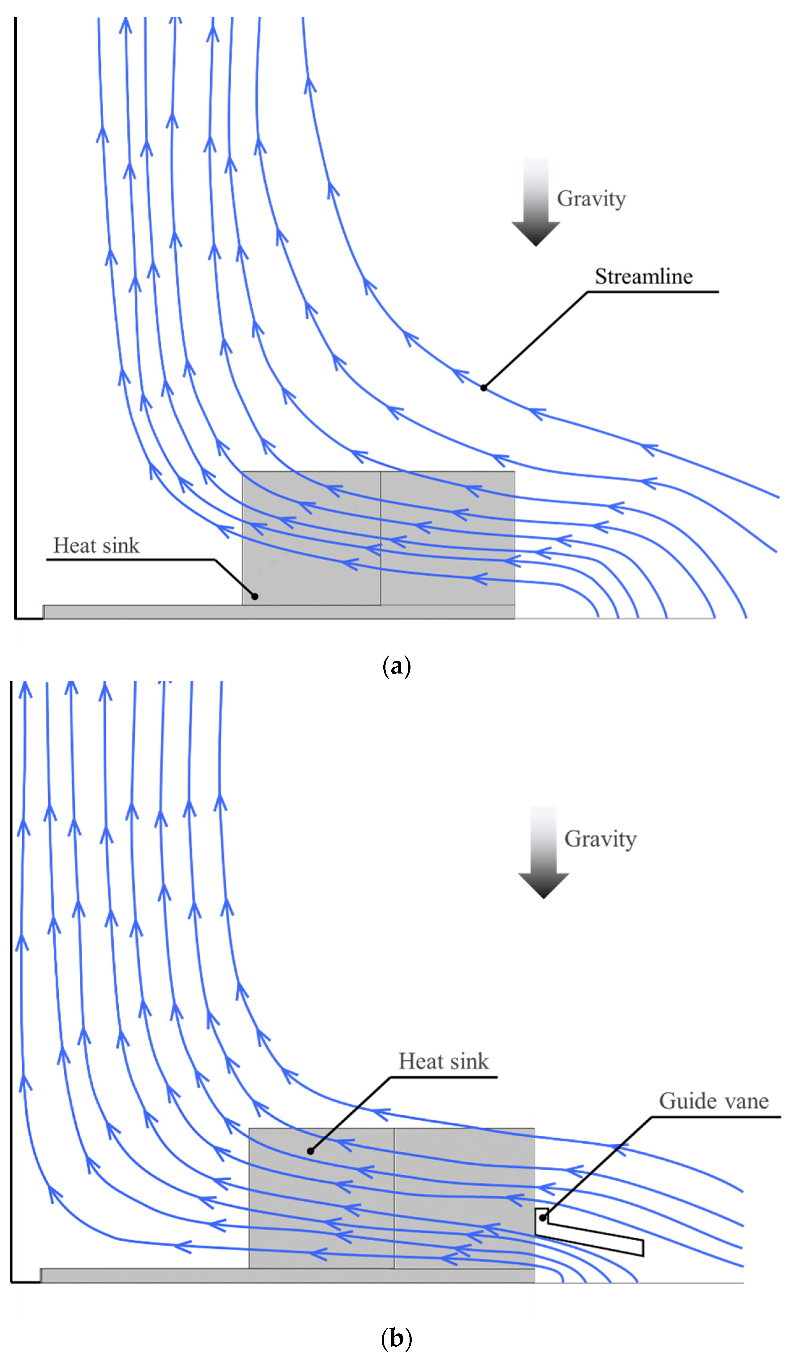
The streamline around the heat sink was shown in Figure 8. The streamline helps to identify the cooling effect due to the installation of the guide vane. Figure 8a is a streamline without a guide vane, and Figure 8b is a streamline with a guide vane installed.
Figure 8.
Streamlines around heat sinks. (a) Without guide vane; (b) with guide vane.
Without the guide vane, the flow does not move deep inside the heat sink center and rises as if passing around the surroundings. However, when a guide vane is installed, a flow is formed in which the flow moved into the center of the heat sink. When comparing the thermal resistance according to the heat flux, the cooling efficiency improved by 9.2% on average when the guide vane was installed (see Figure 6). Therefore, by installing a guide vane, the central portion of the heat sink with the highest temperature is cooled, and the cooling efficiency is significantly improved.
A parametric study was performed to investigate the effects of the guide vane angle (), installation height (), and length () on the thermal resistance (). In order to grasp only the effect of a single factor, the other factors were set constant as a reference (middle value of the range) and were made dimensionless using the following equation.
where
The ranges of the parameters were determined considering the geometrical limitation. The thermal resistance was nondimensionalized as , and the reference value () is the thermal resistance at the reference parameters , , .
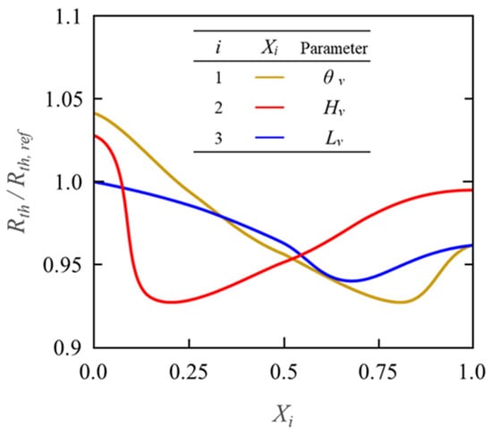
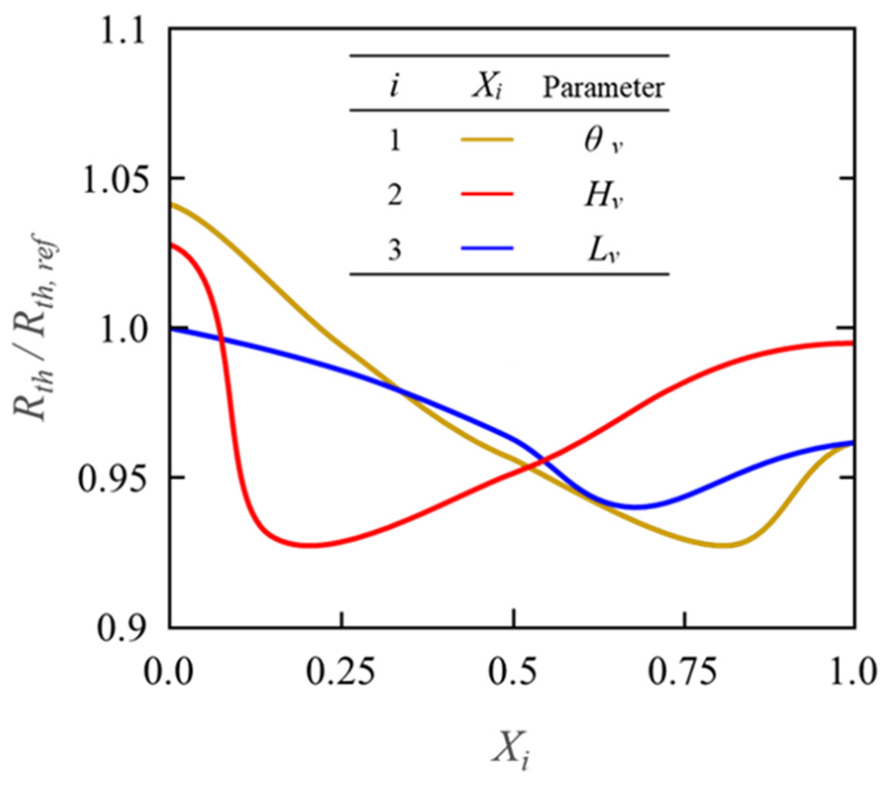
To determine whether each factor has a positive or negative effect on thermal resistance, dimensionless thermal resistance according to was shown in Figure 9.
Figure 9.
Thermal resistance of a heat sink with a guide vane with variation of Xi.
Thermal resistance tended to decrease as X1 (vane angle) increased, and then increased when X1 was greater than 0.82. When the X1 was small, the guide vane did not play a role in changing the flow direction, and the flow moved to the heat sink center when X1 was around 0.82. However, a streamlined flow was not created when the angle was greater than 0.82, and the thermal resistance tended to increase. This means that there is a specific angle that supplies flow into the heat sink and creates an optimal streamline.
The thermal resistance decreased sharply as X2 (installation height) increased, and then increased gradually when X2 was greater than 0.19. The air flowing into the heat sink is small when X2 is less than 0.19, and sufficient flow was supplied at a specific height to the center of the heat sink. However, the thermal resistance tended to increase gradually when X2 was increased above a certain value, since the amount of air supplied to the center-bottom of the heat sink decreased. The streamline was similar to that without the guide vane when X2 was close to 1.
The thermal resistance decreased as X3 (vane length) increased, and then increased when X3 was greater than 0.67. The air flowing into the center of the heat sink increased as the vane length increased, decreasing the thermal resistance, and when it exceeded a certain value, the flow was obstructed, increasing the thermal resistance. In other words, there is an optimal point where the vane moves the flow into the center, not disturbing the flow.
4.2. Optimization
The dimensionless thermal resistance () was set as an objective function, and the design variable was set as Xi for optimization, and it is expressed as an equation as follows.
In total, 25 experimental points were adopted using the orthogonal array (OA) method L25 (53). The object function f (X1, X2, X3) was derived using the Kriging model, and the optimization was conducted using the micro-genetic algorithm (MGA) [29]. The specific parameters of MGA are listed in Table 5. The optimization results were summarized in Table 6 and Table 7. As discussed in Section 4.2 parametric study, there were certain points for Xi that minimized the thermal resistance for all of the parameters, and they were not on the boundaries of the range. When the optimized guide vane was set on the heat sink, the thermal resistance () was improved by a maximum of 17.2% compared to that without guide vane.
Table 5.
Details of micro-genetic algorithm (MGA).
Table 6.
Optimal parameters of a guide vane.
Table 7.
Optimization results (Ts = 20 °C, = 800 W/m2).
Figure 10 shows the temperature contour of the heat sink with the guide vane installed. As can be seen from the figure, the average heat sink temperature with the guide vane is considerably reduced when compared to that without the guide vane shown in Figure 7. For the validity of the numerical analysis in the optimized shape, an experiment was performed, and the numerical and the experimental results were compared and shown in Figure 11. The results of the numerical analysis were in good agreement with the experimental results showing a maximum error of 1.5%. In addition, the cooling efficiency of the heat sink with the guide vane installed was improved by 16.3% on average compared to the heat sink without the guide vane. Therefore, the guide vane helps to cool the center of the heat sink, and the cooling efficiency can be significantly improved.
Figure 10.
Temperature contours of a heat sink with a guide vane (Ts = 20 °C, = 800 W/m2).
Figure 11.
Validation of the optimal results.
5. Conclusions
A guide vane was installed to enhance the cooling effect of a heat sink, and experiments and numerical analysis were conducted. The numerical analysis was conducted to identify the flow and thermal characteristics of the system, and it was verified by comparison with the experimental results. The effect of the guide vane on the cooling performance of the heat sink was investigated. The streamline and temperature contour were analyzed to identify the influence of the guide vane. It was found that the cooling performance was significantly improved by supplying the air to the center bottom of the heat sink. Optimization was conducted to minimize thermal resistance using the Kriging model and micro-genetic algorithm (MGA). As a result of quantitatively grasping the cooling effect of the heat sink, the performance was enhanced by up to 17.2% when the guide vane was installed. It is expected that this study may help solve the overheating problems in heat sink for LED lights operating under natural convection conditions.
Author Contributions
Conceptualization, S.B.; Data curation, S.H.; Formal analysis, S.B.; Methodology, S.B.; Project administration, K.-S.L.; Software, S.H.; Supervision, K.-S.L.; Validation, S.H.; Writing–original draft, S.B.; Writing–review & editing, K.-S.L. All authors have read and agreed to the published version of the manuscript.
Funding
This research was funded by the Korea Institute of Energy Technology Evaluation and Planning (KETEP) and the Ministry of Trade, Industry & Energy (MOTIE) of the Republic of Korea (No. 20184010201710).
Institutional Review Board Statement
Not applicable.
Informed Consent Statement
Not applicable.
Data Availability Statement
Not applicable.
Conflicts of Interest
The authors declare no conflict of interest.
Nomenclature
| A | area [m2] | μeff | effetive viscosity [kg/m s] |
| g | gravitational acceleration [m/s2] | μt | turbulent viscosity [kg/m s] |
| H | height [mm] | arbitrary scalar | |
| k | thermal conductivity [W/m℃] | Subscripts | |
| L | length [mm] | ave | average |
| heat flux [W/m2] | b | heat sink base | |
| heat transfer rate [W] | d | domain | |
| r | radius [mm] | f | fin |
| Rth | thermal resistance [℃/W] | g | glass |
| S | source term | h | heat sink |
| t | thickness [mm] | i | inner or index, i = 1, 2, 3 |
| T | temperature [℃] | in | input |
| u | velocity [m/s] | j | index, j = x, y, z |
| x | design factor | l | long |
| X | normalized design factor | m | middle |
| o | outer | ||
| Greek symbols | ref | reference | |
| Γ | diffusion coefficient | v | guide vane |
| θ | angle [degree] | ||
References
- Ahn, B.-L.; Park, J.-W.; Yoo, S.; Kim, J.; Leigh, S.-B.; Jang, C.-Y. Savings in Cooling Energy with a Thermal Management System for LED Lighting in Office Buildings. Energies 2015, 8, 6658–6671. [Google Scholar] [CrossRef] [Scilit]
- Baran, K.; Różowicz, A.; Wachta, H.; Różowicz, S.; Mazur, D. Thermal Analysis of the Factors Influencing Junction Temperature of LED Panel Sources. Energies 2019, 12, 3941. [Google Scholar] [CrossRef] [Scilit]
- Adhikari, R.; Beyragh, D.; Pahlevani, M.; Wood, D. A Numerical and Experimental Study of a Novel Heat Sink Design for Natural Convection Cooling of LED Grow Lights. Energies 2020, 13, 4046. [Google Scholar] [CrossRef] [Scilit]
- Allwyn, R.G.; Al Abri, R.; Malik, A.; Al-Hinai, A. Economic Analysis of Replacing HPS Lamp with LED Lamp and Cost Estimation to Set Up PV/Battery System for Street Lighting in Oman. Energies 2021, 14, 7697. [Google Scholar] [CrossRef] [Scilit]
- Rammohan, A.; Chandramohan, V.P. Experimental analysis on estimating junction temperature and service life of high power LED array. Microelectron. Reliab. 2021, 120, 114121. [Google Scholar] [CrossRef] [Scilit]
- Olvera-Gonzalez, E.; Escalante-Garcia, N.; Myers, D.; Ampim, P.; Obeng, E.; Alaniz-Lumbreras, D.; Castaño, V. Pulsed LED-Lighting as an Alternative Energy Savings Technique for Vertical Farms and Plant Factories. Energies 2021, 14, 1603. [Google Scholar] [CrossRef] [Scilit]
- Pilagatti, A.N.; Piscopo, G.; Atzeni, E.; Iuliano, L.; Salmi, A. Design of additive manufactured passive heat sinks for electronics. J. Manuf. Process. 2021, 64, 878–888. [Google Scholar] [CrossRef] [Scilit]
- Elshafei, E. Natural convection heat transfer from a heat sink with hollow/perforated circular pin fins. Energy 2010, 35, 2870–2877. [Google Scholar] [CrossRef] [Scilit]
- Ahmadian-Elmi, M.; Mohammadifar, M.; Rasouli, E.; Hajmohammadi, M. Optimal design and placement of heat sink elements attached on a cylindrical heat-generating body for maximum cooling performance. Thermochim. Acta 2021, 700, 178941. [Google Scholar] [CrossRef] [Scilit]
- Tang, Y.; Luo, Y.; Du, P.; Wang, H.; Ma, H.; Qin, Y.; Bai, P.; Zhou, G. Experimental investigation on active heat sink with heat pipe assistance for high-power automotive LED headlights. Case Stud. Therm. Eng. 2021, 28, 101503. [Google Scholar] [CrossRef] [Scilit]
- Lin, X.; Mo, S.; Jia, L.; Yang, Z.; Chen, Y.; Cheng, Z. Experimental study and Taguchi analysis on LED cooling by thermoelectric cooler integrated with microchannel heat sink. Appl. Energy 2019, 242, 232–238. [Google Scholar] [CrossRef] [Scilit]
- Lin, Z.; Wang, S.; Huo, J.; Hu, Y.; Chen, J.; Zhang, W.; Lee, E. Heat transfer characteristics and LED heat sink application of aluminum plate oscillating heat pipes. Appl. Therm. Eng. 2011, 31, 2221–2229. [Google Scholar] [CrossRef] [Scilit]
- Lu, X.-Y.; Hua, T.-C.; Wang, Y.-P. Thermal analysis of high power LED package with heat pipe heat sink. Microelectron. J. 2011, 42, 1257–1262. [Google Scholar] [CrossRef] [Scilit]
- Alvin, C.; Chu, W.; Cheng, C.-H.; Teng, J.-T. Thermal analysis of extruded aluminum fin heat sink for LED cooling application. In Proceedings of the 6th International Microsystems Packaging, Assembly and Circuits Technology Conference (IMPACT), Taipei, Taiwan, 19–21 October, 2011; pp. 397–400. [Google Scholar] [CrossRef] [Scilit]
- Tucker, R.; Khatamifar, M.; Lin, W.; McDonald, K. Experimental investigation of orientation and geometry effect on additive manufactured aluminium LED heat sinks under natural convection. Therm. Sci. Eng. Prog. 2021, 23, 100918. [Google Scholar] [CrossRef] [Scilit]
- De Mey, G.; Wójcik, M.; Pilarski, J.; Lasota, M.; Banaszczyk, J.; Vermeersch, B.; Napieralski, A.; De Paepe, M. Chimney Effect on Natural Convection Cooling of a Transistor Mounted on a Cooling Fin. J. Electron. Packag. 2009, 131, 014501. [Google Scholar] [CrossRef] [Scilit]
- Da Silva, A.K.; Gosselin, L. Optimal geometry of L and C-shaped channels for maximum heat transfer rate in natural convection. Int. J. Heat Mass Transf. 2005, 48, 609–620. [Google Scholar] [CrossRef] [Scilit]
- Shimoyama, R.; Horibe, A.; Haruki, N.; Sano, Y. Natural Convection Heat Transfer from Upward-Facing Horizontal Heated Surface with Heated Cylindrical Pipe (Effects of Flow Characteristic around Heated Cylinder). Trans. Jpn. Soc. Mech. Eng. Ser. B 2013, 79, 2289–2300. [Google Scholar] [CrossRef] [Scilit]
- Park, S.-J.; Jang, D.; Lee, K.-S. Thermal performance improvement of a radial heat sink with a hollow cylinder for LED downlight applications. Int. J. Heat Mass Transf. 2015, 89, 1184–1189. [Google Scholar] [CrossRef] [Scilit]
- Souayeh, B.; Yasin, E.; Alam, M.W.; Hussain, S.G. Numerical Simulation of Magnetic Dipole Flow Over a Stretching Sheet in the Presence of Non-Uniform Heat Source/Sink. Front. Energy Res. 2021, 9. [Google Scholar] [CrossRef] [Scilit]
- Li, B.; Baik, Y.-J.; Byon, C. Enhanced natural convection heat transfer of a chimney-based radial heat sink. Energy Convers. Manag. 2016, 108, 422–428. [Google Scholar] [CrossRef] [Scilit]
- Lopez, M.J.S.; Blanco-Marigorta, A.M.; Trashorras, A.J.G.; Pistono-Favero, J.; Blanco-Marigorta, E. Numerical simulation and exergetic analysis of building ventilation solar chimneys. Energy Convers. Manag. 2015, 96, 1–11. [Google Scholar] [CrossRef] [Scilit]
- Yakhot, V.; Orszag, S.A. Renormalization group analysis of turbulence. I. Basic theory. J. Sci. Comput. 1986, 1, 3–51. [Google Scholar] [CrossRef] [Scilit]
- Jang, D.; Yook, S.-J.; Lee, K.-S. Optimum design of a radial heat sink with a fin-height profile for high-power LED lighting applications. Appl. Energy 2014, 116, 260–268. [Google Scholar] [CrossRef] [Scilit]
- Sani, F.H.; Pourfallah, M.; Gholinia, M. The effect of MoS2–Ag/ H2O hybrid nanofluid on improving the performance of a solar collector by placing wavy strips in the absorber tube. Case Stud. Therm. Eng. 2022, 30, 101760. [Google Scholar] [CrossRef] [Scilit]
- Gholinia, M.; Ranjbar, A.; Javidan, M.; Hosseinpour, A. Employing a new micro-spray model and (MWCNTs—SWCNTs)—H2O nanofluid on Si-IGBT power module for energy storage: A numerical simulation. Energy Rep. 2021, 7, 6844–6853. [Google Scholar] [CrossRef] [Scilit]
- Shaker, B.; Gholinia, M.; Pourfallah, M.; Ganji, D. CFD analysis of Al2O3-syltherm oil Nanofluid on parabolic trough solar collector with a new flange-shaped turbulator model. Theor. Appl. Mech. Lett. 2022, 100323. [Google Scholar] [CrossRef] [Scilit]
- Coleman, H.W.; Steele, W.G. Experimentation, Validation, and Uncertainty Analysis for Engineers; John Wiley & Sons: Hoboken, NJ, USA, 2018. [Google Scholar]
- Sacks, J.; Welch, W.J.; Mitchell, T.J.; Wynn, H. Design and Analysis of Computer Experiments. Stat. Sci. 1989, 4, 409–423. [Google Scholar] [CrossRef] [Scilit]

Publisher’s Note: MDPI stays neutral with regard to jurisdictional claims in published maps and institutional affiliations. |
© 2022 by the authors. Licensee MDPI, Basel, Switzerland. This article is an open access article distributed under the terms and conditions of the Creative Commons Attribution (CC BY) license (https://creativecommons.org/licenses/by/4.0/).