


Abstract
The power inverter topologies are indispensable devices to incorporate distributed generation schemes, like photovoltaic energy sources into the AC main. The nonlinear behavior of the power inverter draws a challenge when it comes to their control policy, rendering linear control methods often inadequate for the application. The control complexity can be further increased by the LCL filters, which are the preferred way to mitigate the current ripple caused by the inverter switching. This paper presents a robust variable structure control for a three-phase grid-tied inverter with an LCL filter. As well to the benefits of the sliding mode control (SMC), which is one of the control methods applied by power converters founded in literature, the proposed control scheme features a novel partial state observer based on the immersion and invariance technique, which thanks to its inherent robustness and speed of convergence is adequate for this application. This observer eliminates the need for physical current sensors, decreasing the overall cost and size, as well as probable sources of noise. The proposed controller is meant for a three-phase grid-tied inverter to inject active power to the grid while harmonics generated by nonlinear loads are compensated. The simulation results prove the effectiveness of the proposed method by compensating for current harmonics produced by the nonlinear loads and maintaining a low total harmonic distortion as recommended by the STD-IEEE519-2014, regardless of whether the system provides active power or not.
1. Introduction
Solar energy is the most popular alternative energy source around the world, thanks to technological advancements, and the reduction in rooftop photovoltaic systems prices, in particular, has rapidly increased installation numbers around the world [1]. several works present interesting results, control algorithms, and power electronics topologies for using this kind of energy source, some of them, are focused on improving grid-tied inverters because they are the primary power converters connecting photovoltaic systems to the utility grid. Shunt active power filters have been widely studied due to its properties and capabilities to compensate current harmonics, reactive power compensations, and other kinds of power quality issues, in [2] a financial point of view is devoted to implement a conventional topology of shunt active power filter, a modification theory to accomplish different standards is proposed as well traditional methodologies to obtain the reference signals. In [3] different methodologies to calculate the harmonics reference signal are studied. An interesting and extended analysis of PQ theory and dq0 reference frame are discussed and analyzed too, nonetheless, a different method is proposed to avoid the low pass filter used in PQ and dq0 frames. Direct power control (DPC) is used in [4]. The control algorithm based on DPC simplifies the control scheme and directly involves the PQ components in the active power and reactive power compensation is deeply discussed and studied in the same reference. In [5], a single-phase H-bridge current source inverter topology is proposed, the research is devoted to suggesting a decoupling control of phase current in current source grid-connected inverters. The DC side of this current source inverter topology can operate with a common DC bus or independently, and the AC side can be separately integrated into the three-phase grid or operate in parallel. In [6], a symmetric single-source seven-level inverter with voltage balance and the diode clamped DC-AC converter is presented. The control strategy allows that only one semiconductor device is commuted at any time. A transformer-less grid-tied inverter is presented in [7], and a detailed analysis of H4, H5 and H6 transformer-less converters is carried out. DC side decoupled circuits are studied to eliminate the leakage current. As the usage of distributed energies becomes more widespread, the power inverters connected to the grid increase. Nonetheless, the nonlinear nature of the power converters introduces harmonics to the AC-main [8]. This harmonic pollution negatively affects the devices connected to AC - main as well as the operation of the power system; these effects range from reductions of efficiency of power generation to damaging sensitive equipment such as computers, and other electronic devices. The waveform distortions caused by harmonics also reduce efficiency and force suppliers to provide more power due to ghost distortive power [9]. In order to mitigate the associated harmonic effects on the grid power several standards to determine requirements as well as recommended practices for distributed generation are worked in reference [10]. Electric Power Research Institute published protocols for photovoltaic grid integration that includes harmonic compensation methods and control modes [11]. In [12,13], active power filters are used to compensate harmonics, then it is possible to extend the functions performed by the grid-tied inverters, due to it has been reported that they are capable to perform multiple functions involving both active power control, and reactive power control [14]. A hybrid energy system composed of photovoltaic panels, wind turbines, and fuel cells that utilize active power an active power filter is presented in [15], this system has proven capable of decreasing harmonic levels when presented with balanced, unbalanced, and nonlinear loads. In [16] a three-level inverter topology was successfully used as an active power filter on steady-state and dynamic states. Active filtering was applied to a wind power system in [17] using the conservative power theory and verifying the applicability of this theory to active power filters through orthogonal decomposition. A control strategy for a single-phase active power filter was proposed in [18], this control strategy was applied to a modified packed U-cell five-level inverter to eliminate harmonics and compensating reactive power. In distributed renewable energy generation is common to use the reactive power control that takes advantage of the reactive power available in distributed renewable sources to address problems with power quality, these methods have been enhanced by combining them with active power curtailment methods and improve the regulation of voltage [19]. Ref. [20] presents a voltage regulation system that takes advantage of both the active power and reactive power of the photovoltaic inverter, as well as a 15-s power forecast. A distributed control scheme is presented in [21], which features low communication requirements, and the droop control method is applied to active power and reactive power. Therefore, the importance of research and development of control algorithms used in PV inverter controllers for sustainable renewable energy applications [22], given that with this, it is possible to guarantee that a PV system contributes to generating clean energy without compromising the availability and reliability of the electricity supply. The control law of the power inverter has its aim to ensure the output variable is controlled, so it resembles and tracks the desired output. In [23], the dynamic model considering system uncertainties of the grid-tied converter is described for the global integral sliding mode control design. In this sense, to overcome the chattering phenomena and the dependence of the dynamic information in the global integral sliding-model control, a model-free dynamic recurrent fuzzy neural network approximates the global-integral sliding mode control law without an extra compensator. The sliding mode control is of interest because it is a particular class of variable structure systems and, it is considered a fast and robust nonlinear control technique suitable for regulating switched controlled systems [24]. The SMC consists of a discontinuous time-varying state feedback control law, which changes at high frequency from one continuous structure to another according to the current position of the state variables in the states-pace, the aim is to force the dynamics of the system under control to follow a variety of sliding surface and force them to evolve on it [25]. The major advantage of an SMC system is that it has guaranteed stability and robustness against parameter uncertainties. Also, being a control method with high flexibility in design choices is relatively easy to implement compared to other nonlinear control methods [26]. Such properties make the SMC very suitable for non-linear systems therefore, it is widely used in industrial applications such as electrical controllers as grid-connected converters and multilevel inverters [27,28,29]. Also, it is reported a sliding mode control of a three-phase grid connected, the control strategy provides control with less settling time, overshoot, oscillating response [30]. All the above, it is critical to developing an effective reactive power compensation strategy in real-time for the grid-connected PV system and the SMC properties that make it very suitable for the non-linear system present. In this paper, the design, implementation, and performance analysis of a proposed control scheme with power factor improvement is presented. It is important to highlight that the proposed SMC is developed from a grid-connected PV system presented in previous work [31,32], where a passivity-based control theory is proposed for power factor improvement and harmonic cancellation. The proposed SMC aims to improve inverter performance and ensure power factor compensation to develop a more robust sliding mode control based to guarantee stability and against parameter uncertainties. In this article, a sliding mode controller brings robustness and fast dynamic response to a PV inverter system, it also allows for compensation of low power factor, high harmonic distortion, and three-phase unbalanced loads, which are the most common power quality issues. Furthermore, the proposed control scheme includes an Immersion and Invariance observer that estimates the system currents from the measurement of the capacitor voltages. The contributions of the proposed control scheme are highlighted below.
- Solving power quality issues in three-phase systems using a photovoltaic grid-tied inverter.
- The development of a sliding mode control scheme that provides the grid tied PV inverter with the capability to compensate reactive power, to mitigate harmonic distortion and to balance the three-phase currents.
- The reference currents are calculated using the DQ0 reference frame transformation. The resulting reference signals provide the controller with information required to compensate for reactive power, harmonic distortion, and unbalance voltage.
The remainder of this paper is organized as follows: in Section 2 the electronics power converters as well as the proposed electrical system is presented. In the Section 3 a control scheme strategy is depicted. The simulation results of some typical tests are exposed in Section 4. Finally, the concluding remarks are given in Section 5.
2. Power Stage Description
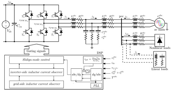
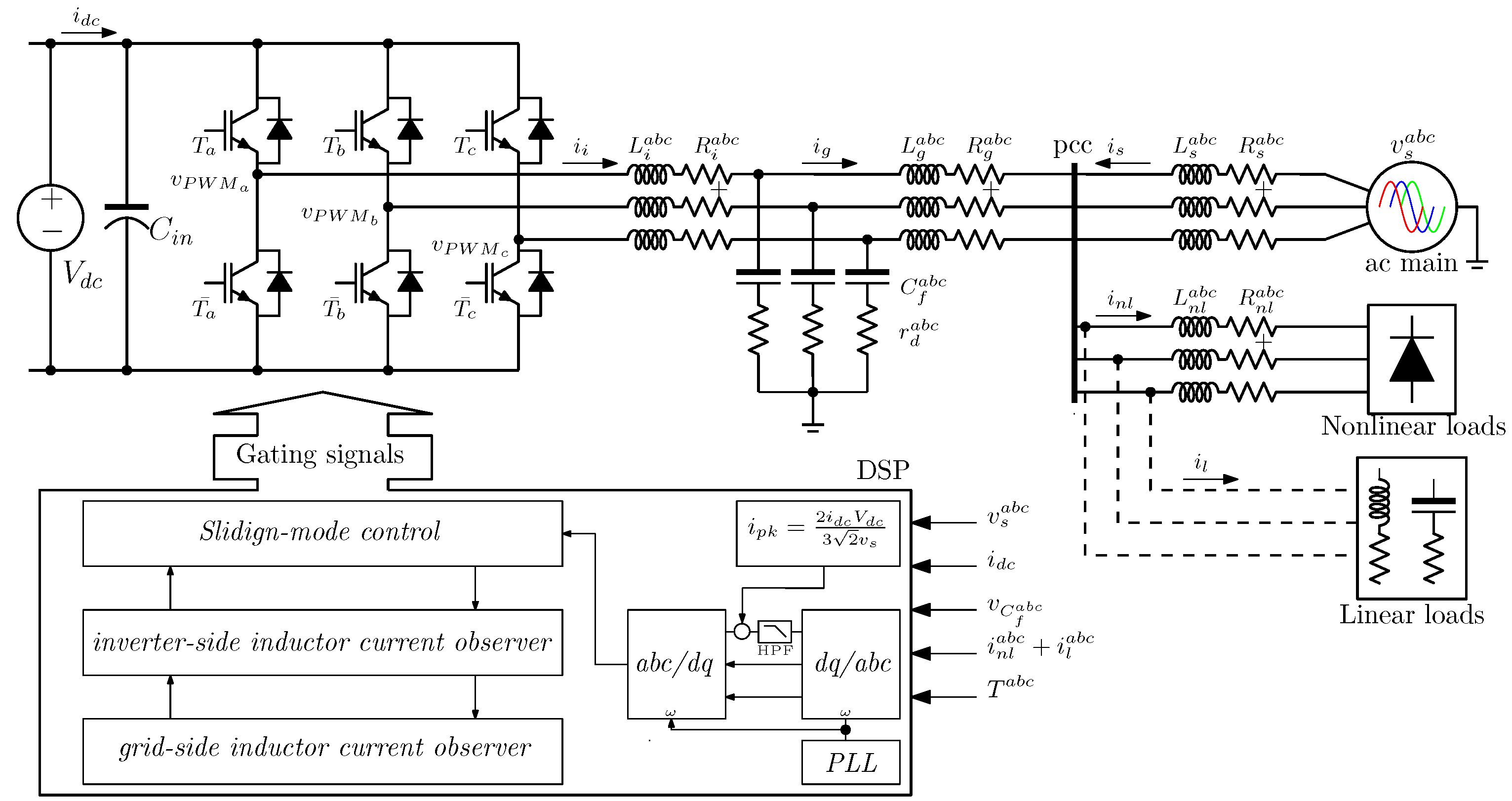
The power stage is shown in Figure 1, this consists on a three–phase grid–tied inverter via LCL filter, in this case, a photovoltaic panel set is represented as a DC source. The inverter is plugged in to a common connection point to the AC–main in joint with other kind of power loads. The control scheme and the processing signal is represented as functional blocks. Next sections will describe each stage of the whole control stage.
Figure 1.
Grid–tied three-phase inverter as active filter functioning.
2.1. Mathematical Modeling of Power Converter
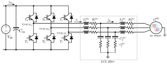
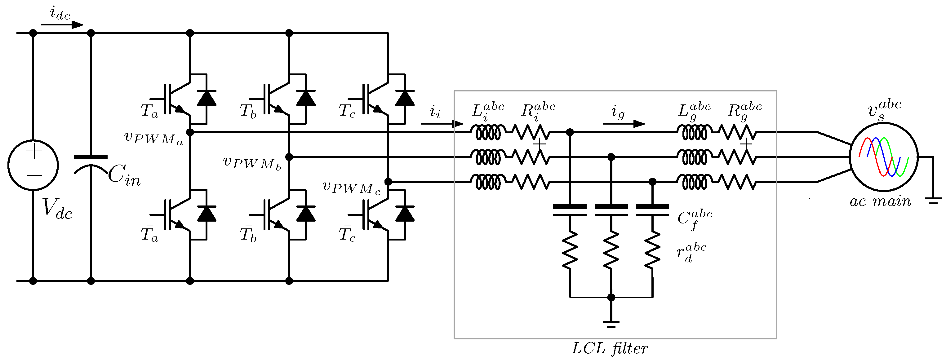
In order to synthesize the control law, it is necessary to obtain a mathematical model. To this case, the power converter with LCL filter used is presented as shown in Figure 2. As can be appreciated, the power converter is a two-level inverter connected to the AC-main via LCL filter, the main goal of the LCL filter is to mitigate current ripple caused by the switching effect of the modulation technique.
Figure 2.
Three-phase inverter topology.
To obtain an adequate model as simple as possible it is necessary to establish the following assumptions:
- Parasitic resistances associated to the inductors are zero,
- Damping resistances in series capacitors are zero,
- Voltages are balanced (i.e., ),
- Currents are balanced (i.e., ).
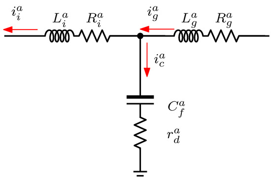
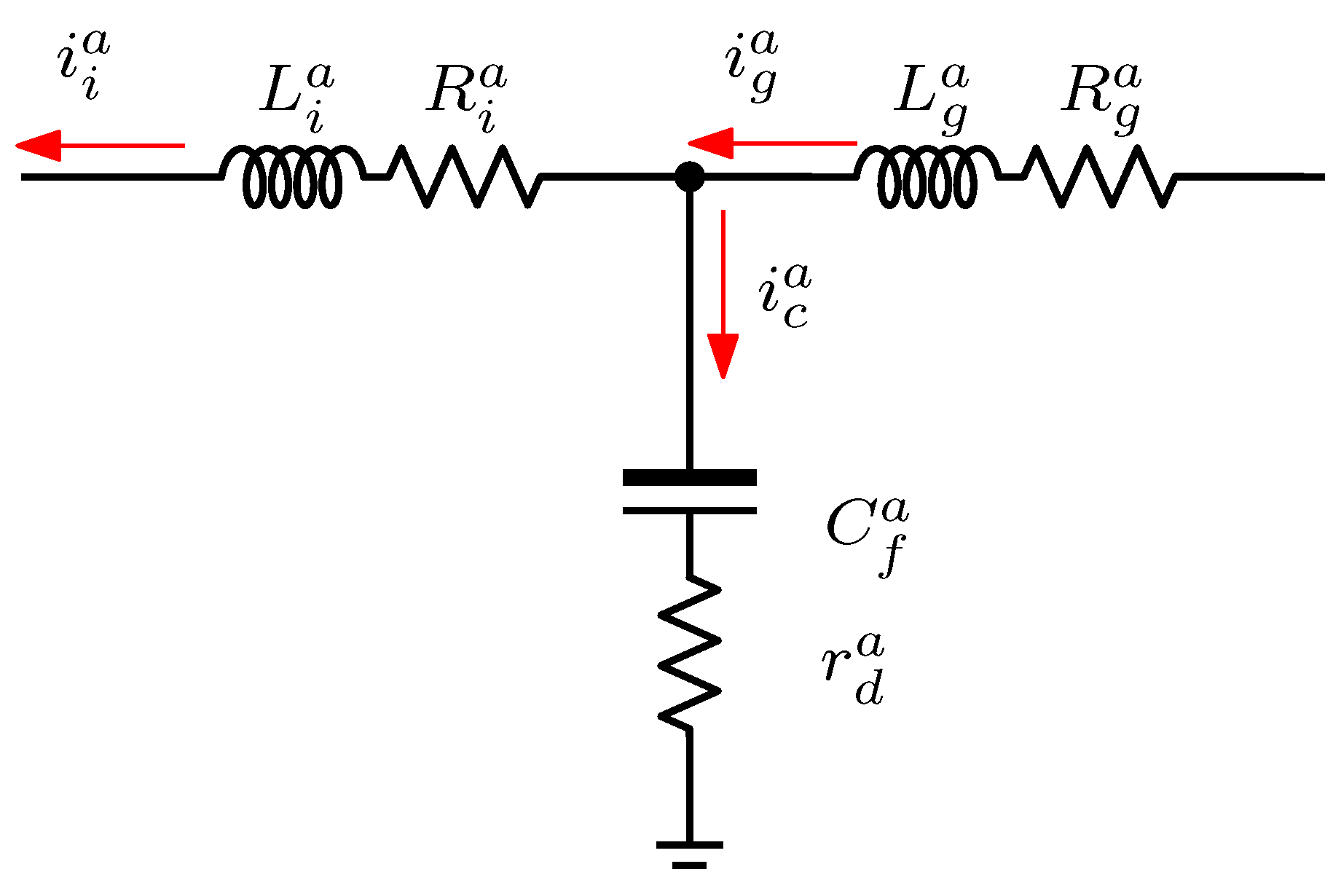
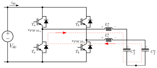
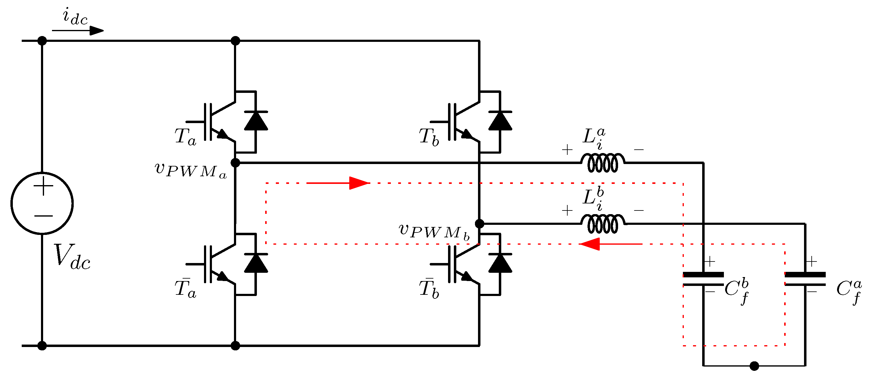
With the assumptions previously mentioned, the mathematical model of the inverter can be obtained using Kirchhoff laws as follows. Firstly, with only one phase–leg and applying Kirchhoff currents law to the simplified circuit shown in Figure 3. the nodal analyzed is obtained.
Figure 3.
Nodal electrical circuit: simplified scheme.
Using Figure 3, one can observe that there is one current flowing into the junction, the grid side inductor current (), and two currents leaving the junction, the capacitor current () and the inverter side inductor current (), in this way we obtain the nodal equation (as can be see the analysis will be applied to the other LCL phases–leg ):
Remember that , where is the capacitor voltage, hence the Equation (1) can be rewritten as:
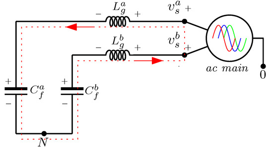
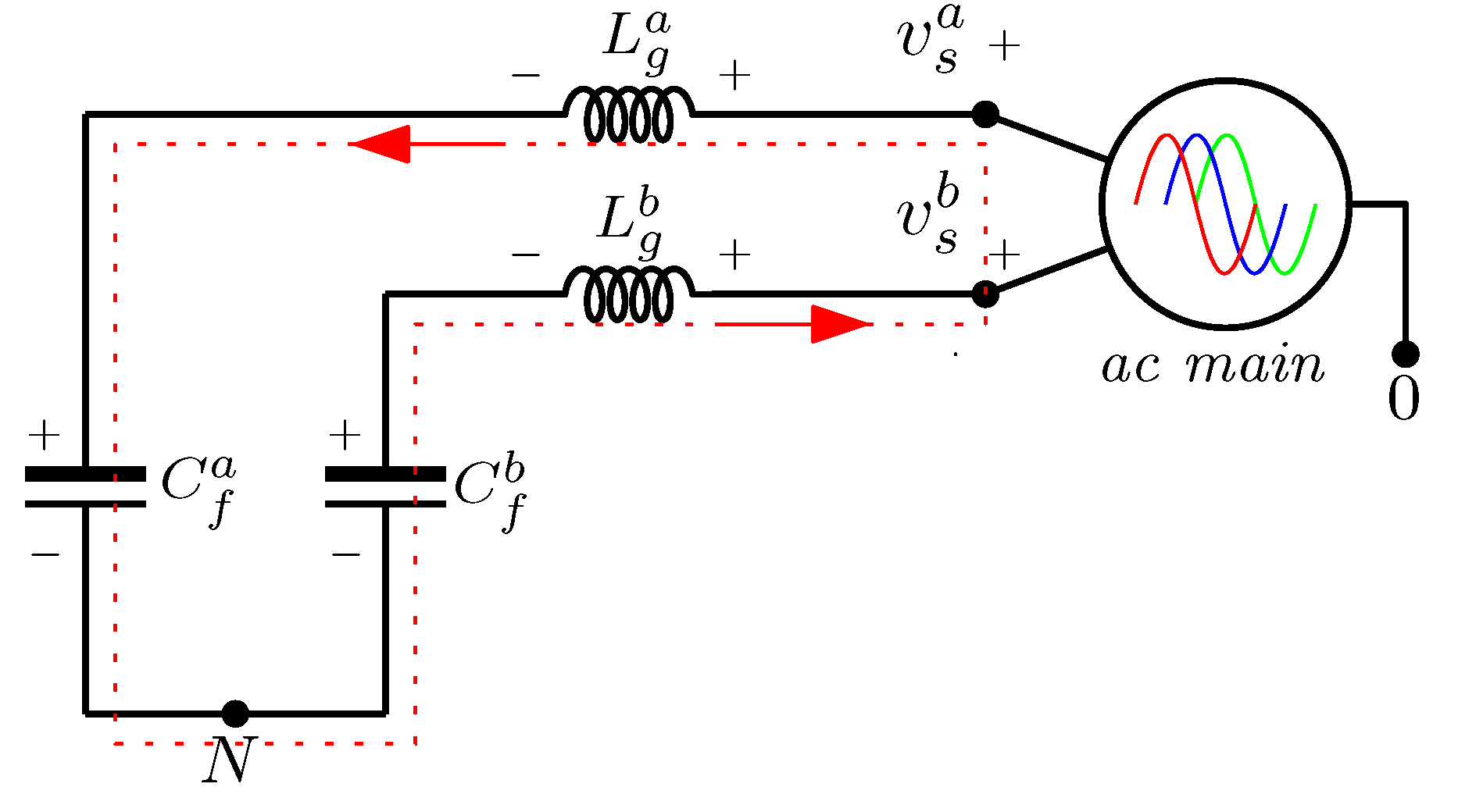
Now, the grid–side mesh can be drawn as shown in Figure 4, taking into account the previous assumption, and using Kirchhoff voltages law, the voltages equation can be obtained. After all, it is important to note that 0 represents the common point of the AC–main sources, and N the junction point of the wye connection of the capacitors.
Figure 4.
Grid–side mesh: simplified circuit.
As the voltage sources and flowing currents are balanced (previously defined), then the mesh equivalent equation can be expressed, taking into account the voltage between the points 0 and N (), as follows,
or in function of the phase–leg b
where and are the AC–main voltages of each a and b phase, respectively; and are the voltages of the grid–side inductors that correspond to a, and b phases respectively; and and are the voltages of the capacitors that correspond to a, and b phases respectively. Therefore, replacing (3) in (4) we obtain:
As formally expressed that and , where and are the grid–side inductor currents that correspond to phases a and b, respectively. So, we can obtain the following equation:
Finally, with the aim of representing the model of the power electronic converter and LCL filter, the last stage is the inverter side mesh, its simplified circuit is presented in Figure 5. Note that, again, only two phase-legs are considered.
Figure 5.
Inverter–side mesh: simplified circuit.
As the analysis above, using Kirchhoff voltages law, the last mesh voltage equation can be obtained as follows:
where , and are defined instead of and , respectively. and are the voltages across terminals of the inverter–side inductors that correspond to phases a and b.
Replacing and that , where and are the inverter side inductor currents that correspond to phases a and b, respectively, Equation (7) can be rewritten as:
As established above a balanced three-phase system, the mathematical model that describes the behavior of the converter illustrated in Figure 2 is summarized by the set of equations as:
where , and are the capacitor voltages; , and are the grid–side inductor currents; , and are the inverter–side inductor currents; , and are the grid–voltages; and , and are the pwm inverter voltages (instead of , , and ). The inverter voltages are defined as , and , where , and are the control signals of the terminals of the inverter (), and is the output of the DC voltage source.
2.2. LCL Filter Tuning
By mean methodology proposed in [33], the values of the LCL filter parameter were obtained. Note that the tuning and sizing of the LCL filters require rules to make sure they filter out the desired harmonics components.
The maximum total inductor value () is obtained with (21). Maintaining the sum of the LCL filter inductor values lower than pH guarantees the voltage drops at the fundamental frequency will be negligible and improves the system response rate.
where is the grid nominal line to line RMS voltage; is the nominal grid frequency and is the active power of the system.
Higher filter capacitor values affect the power factor negatively. For the wye topology used in this work a limit capacitor value (), that maintains a unitary power factor, can be obtained with:
The inverter–side inductor is tuned to attenuate the inverter–side current ripples. The minimum value for the inverter–side inductor () is obtained with:
where is the dc–link voltage; is the inverter switching frequency and is the maximum inverter side current ripple produced when the control signal switches between low and high logical levels. The value of must be lower than . The grid side inductor () is tuned in order to attenuate grid current harmonics. The relation between the grid side inductor and the inverter side inductor is defined as in (24):
The value of is determined with:
where is the proposed harmonic attenuation rate, is the switching frequency and is the proposed value for the filter capacitor.
LCL filters have an inherent resonance frequency, to avoid problems caused by it a damping resistor () is added in series with the filter capacitor. This resistor must be tuned to properly damp the resonance frequency, this is done via the Equation (26)
where is the resonance frequency.
3. Controller Design
This section is devoted to synthesizing the methodology to design the control policy. The aim of proposed control scheme is to reduce the harmonic current demand to the grid by injecting currents that diminish the total harmonic distortion. Furthermore, active power from the DC-link voltage also is delivered to the grid.
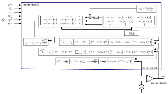
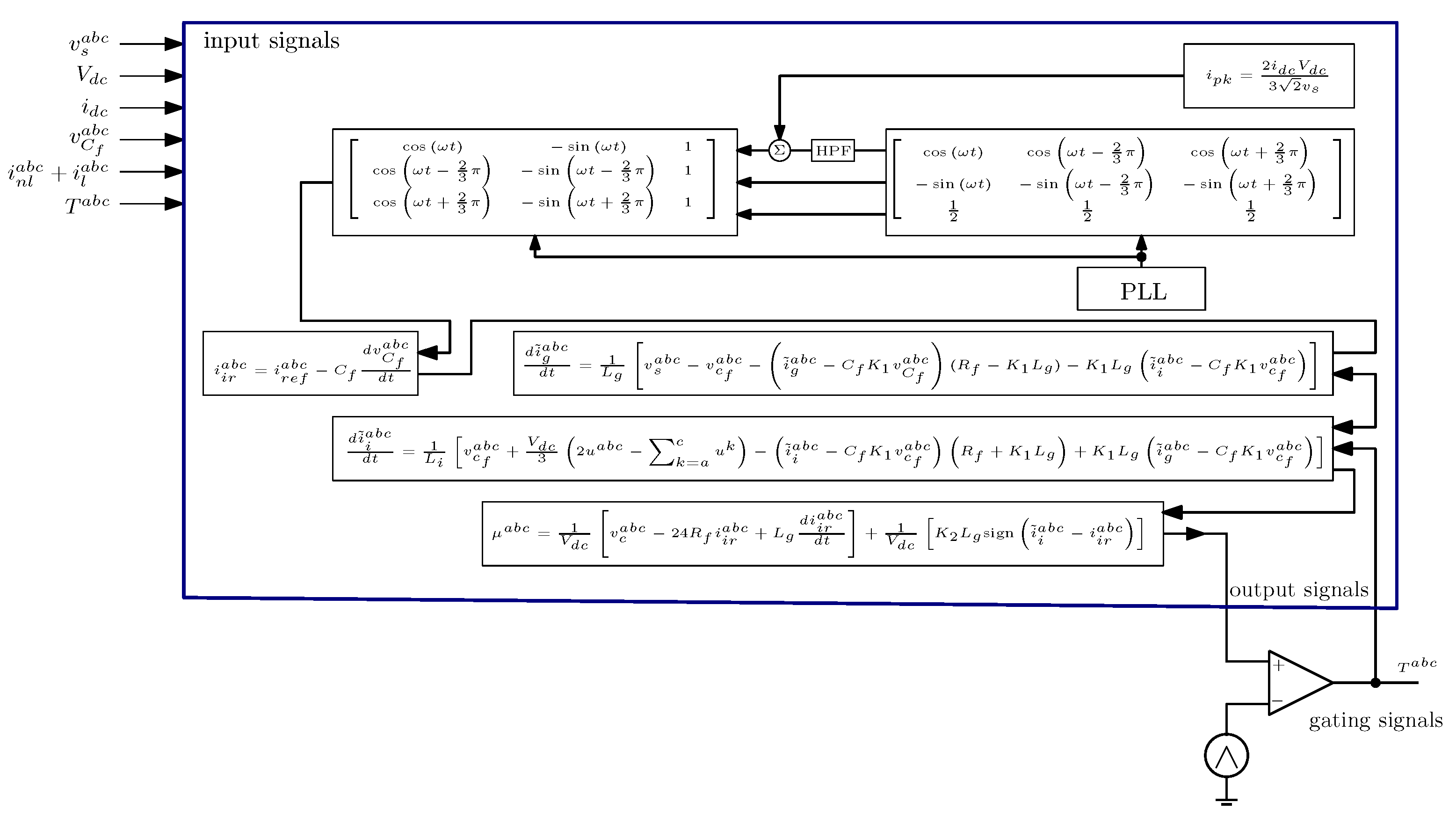
The overall structure of the resulting control scheme summarized in Figure 6. This diagram, shows each stages of the control policy as well as current observer. The input and output signals are illustrated in the same figure.
Figure 6.
Control plus observer stage configuration.
On the next sections, the controller and observer are designed.
3.1. Sliding Mode Controller Design
The proposed control scheme aims to achieve a robust control that drives the error to zero by forcing the system to evolve over a sliding surface. In this case the sliding surface is defined as:
where is the inverter–side inductor current references vector. The time derivative of the sliding surface is:
The control signal guarantees the system dynamics remains on the sliding surface. An additional control signal is needed to drive the system to the sliding surface. To achieve this, the following candidate Lyapunov function is proposed:
whose time derivative is given by:
The attractiveness of the sliding surface is ensured if . Therefore, it is imposed that
Finally, solving (36) for , the complete control law is achieved.
This control law is capable of driving the system to the proposed sliding surface and forcing it to evolve in this surface to guarantee stability.
3.2. Reference Calculation
A point of great interest for this control scheme is the way in which the inverter side inductor currents reference is obtained. These signals are necessary for the compensation, they must be of the required amplitude and with the minimum possible phase shift.
In this work, the reference is obtained by means of the dq transformation, which performs a change of coordinates to a synchronous rotating reference frame, at the frequency of the electrical grid. Equation (38) presents the three-phase dq0 reference frame transformation.
with
where mapping the active components and represents the components in phase with the AC–main signals (voltages or currents), constitutes the components in quadrature with the d component, and it contains the reactive components information, are the load currents. Finally, is the fundamental frequency of the AC-main, this frequency is synchronized using a phase-locked loop (PLL).
The current references () must contain the compensation information, which involves the harmonic content and reactive power demanded by the linear and nonlinear loads. The component provides information on active power. The harmonic compensation references are obtained by eliminating the fundamental component by mean a high-pass filter tuning to eliminate the fundamental component, which allows for the acquisition of harmonic components () at frequencies greater than the fundamental frequency. In addition, the reference includes the active power information related to the PV array active power that flows into the grid. A power estimator (40) takes advantage of this power balance to calculate the peak current of each phase grid.
where is the current of the PV array, is the peak value of the fundamental frequency current injected to each grid phase and is the peak voltage grid.
Now, the reference is obtained by means the inverse dq0 transformation as is depicted in (41). The components and do not require any processing, and are directly used.
with
Finally, from the reference signals, the compensation reference signals are obtained using:
3.3. Inductor Current Estimator
Observers are widely used in systems where there are variables that are difficult to measure. They have also been used to confirm the correct operation of sensors, to detect faults or to replace them. This reduces the number of elements in the control scheme and therefore also reduces the number of sources of error [34]. The use of observers to estimate variables whose measurements are polluted result in less noisy feedback signals than those of a sensor, maintaining great accuracy without additional physical elements.
This section covers the design of the observer used in the system. The immersion and invariance observer was selected due to its structure, robustness and convergence speed. The properties above mentioned make it suitable to be applied in the proposed research. The observer selected is used to estimate the inductor currents based on measurements of the capacitor voltages , , . These electrical variables were chosen because the sensors used to measure them are less sensitive to noise.
First of all, to synthesize this kind of observer, one define the estimation error as (44)
where , are the estimated inductor currents, and is a function of defined to drive the estimation error to zero.
Note that,
The dynamics of the error are made to converge to zero by the time derivative of (44), which is
For convenience, we will use
where , with and .
Replacing the time derivatives in the observer error dynamics (47) we obtain:
Now, is obtained from the error definition (44) and is replaced in (48) to eliminate the measured currents from the error dynamics. Then, the observer error dynamics (48) can be written as (49)
If the observer (50) is defined as follows
the observer error dynamics (49) is reduced to
it is clear that the stability of the observer error dynamics is guaranteed if the matrix is at least semidefinite negative. This is achieved defining with .
Remark 1.
The definition of is not unique.
Finally, the observer error dynamics becomes.
4. Simulation Results
In order to demonstrate the effectiveness of the proposed control scheme and current observers, simulations results under different scenarios are presented. The block diagram illustrated in Figure 6 is programmed in C++ language and compiled as dynamic link library (DLL) which emulates a digital signal processor (DSP).
As can be seen, the output signals control (modulation signals) are compared against carrier signal (triangular waveform), and gating signals are feedback to DSP to be processed by the grid current observer. All measured signals required by the control scheme and observers are indicated in the same Figure.
The power electronic converter showed in Figure 1 was implemented in PSIM software under different scenarios. The parameters used in the simulation of the power converter as well as power loads, and electrical system are given in Table 1.
Table 1.
Simulation Parameters.
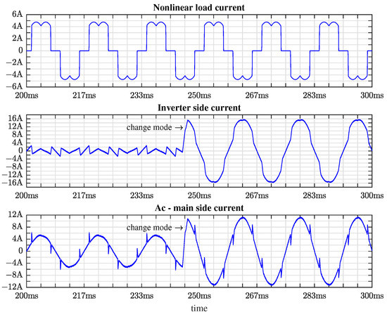
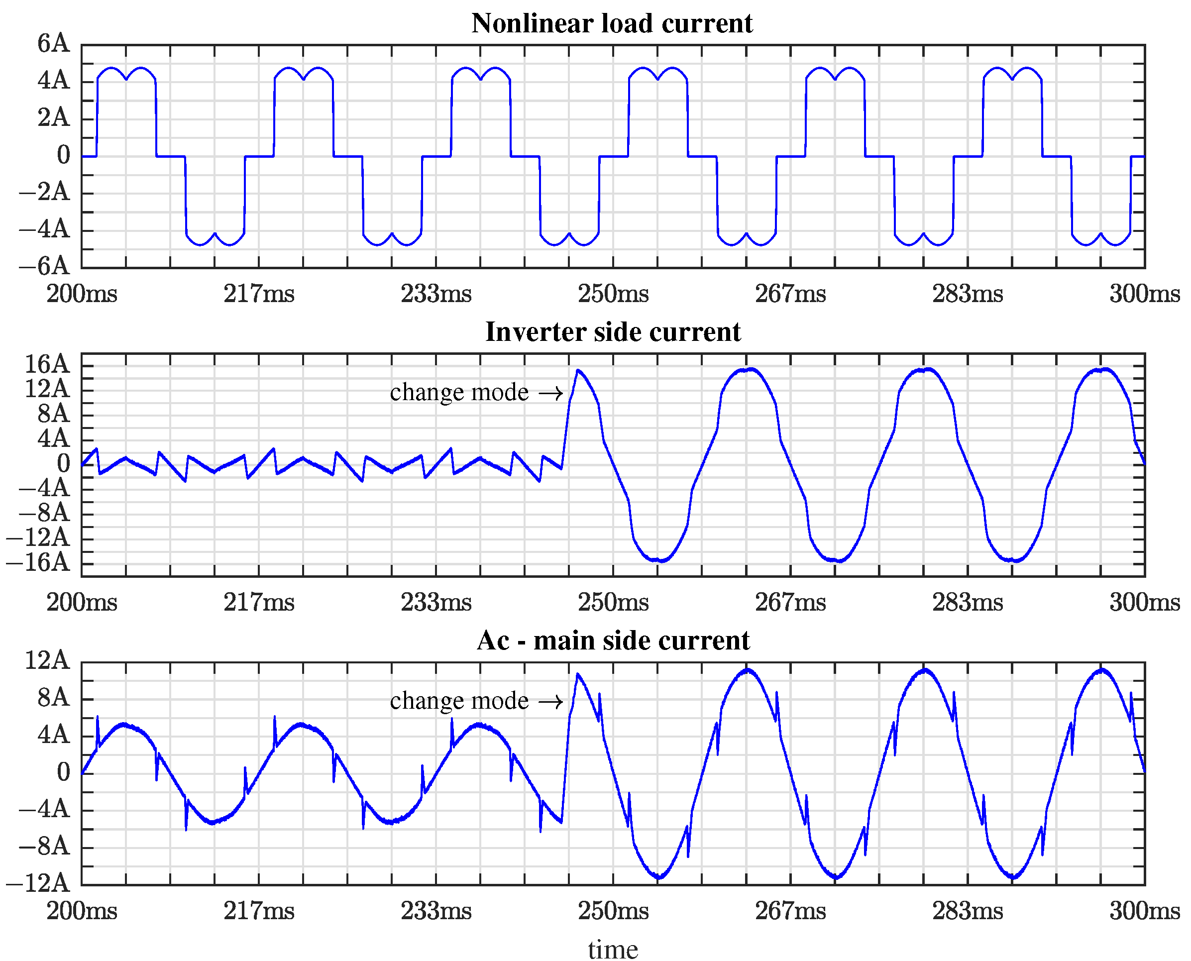
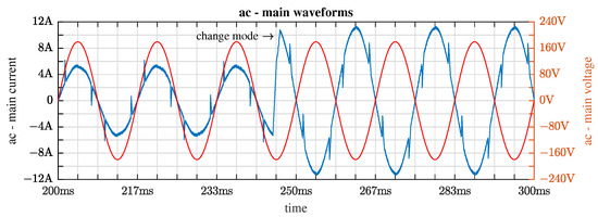
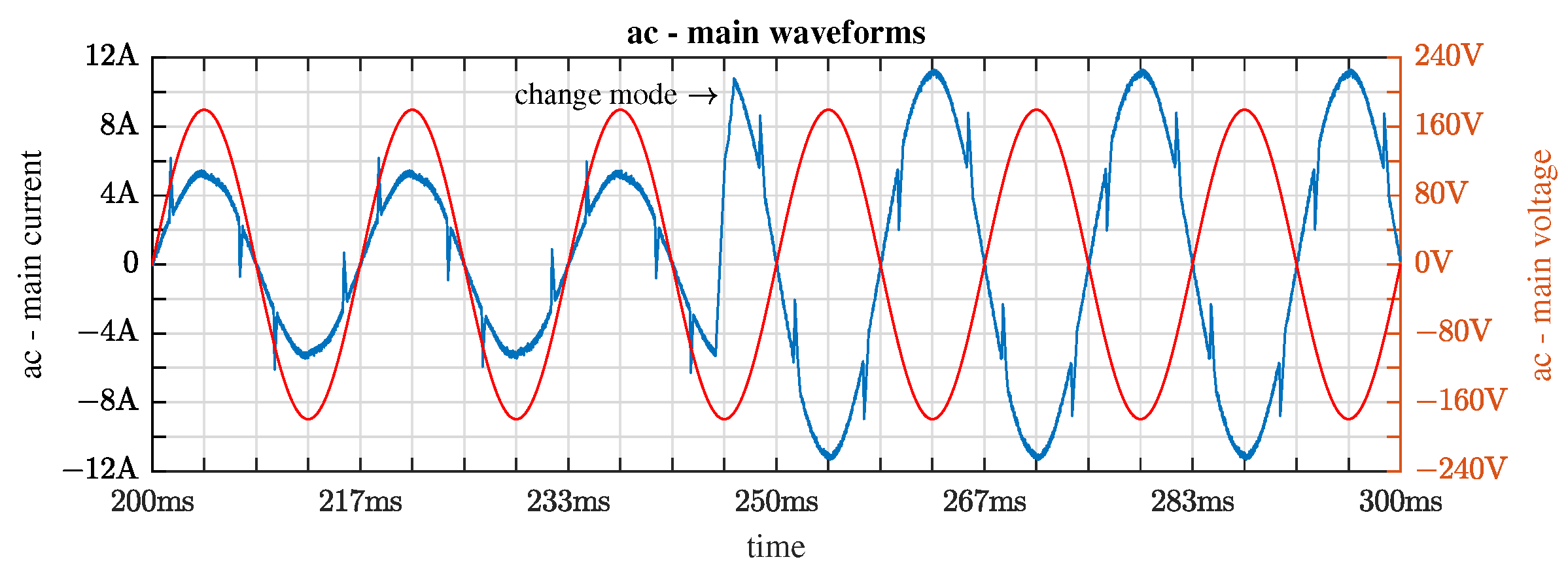
In the first test, the circuit shown in Figure 1 acts as shunt active power filter, the non-linear load is a three-phase diode rectifier. At this time, the power converter compensates harmonics such as is illustrated in Figure 7. In approximately 246 ms the system changes the operation, acting as shunt active power filter and providing active power to the electrical system. Notice that the current and voltage are in phase opposite as is shown in Figure 8. In the same figure, the time response of the observers can be appreciated. Under several iterative simulations, the minimum time response is approximately 50 milliseconds.
Figure 7.
Main waveforms in power converter: from top to bottom, non linear load current, inverter side current (compensation current), ac-main current (compensated current).
Figure 8.
Ac-main electrical waveforms: current (blue) and voltage (red).
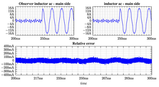
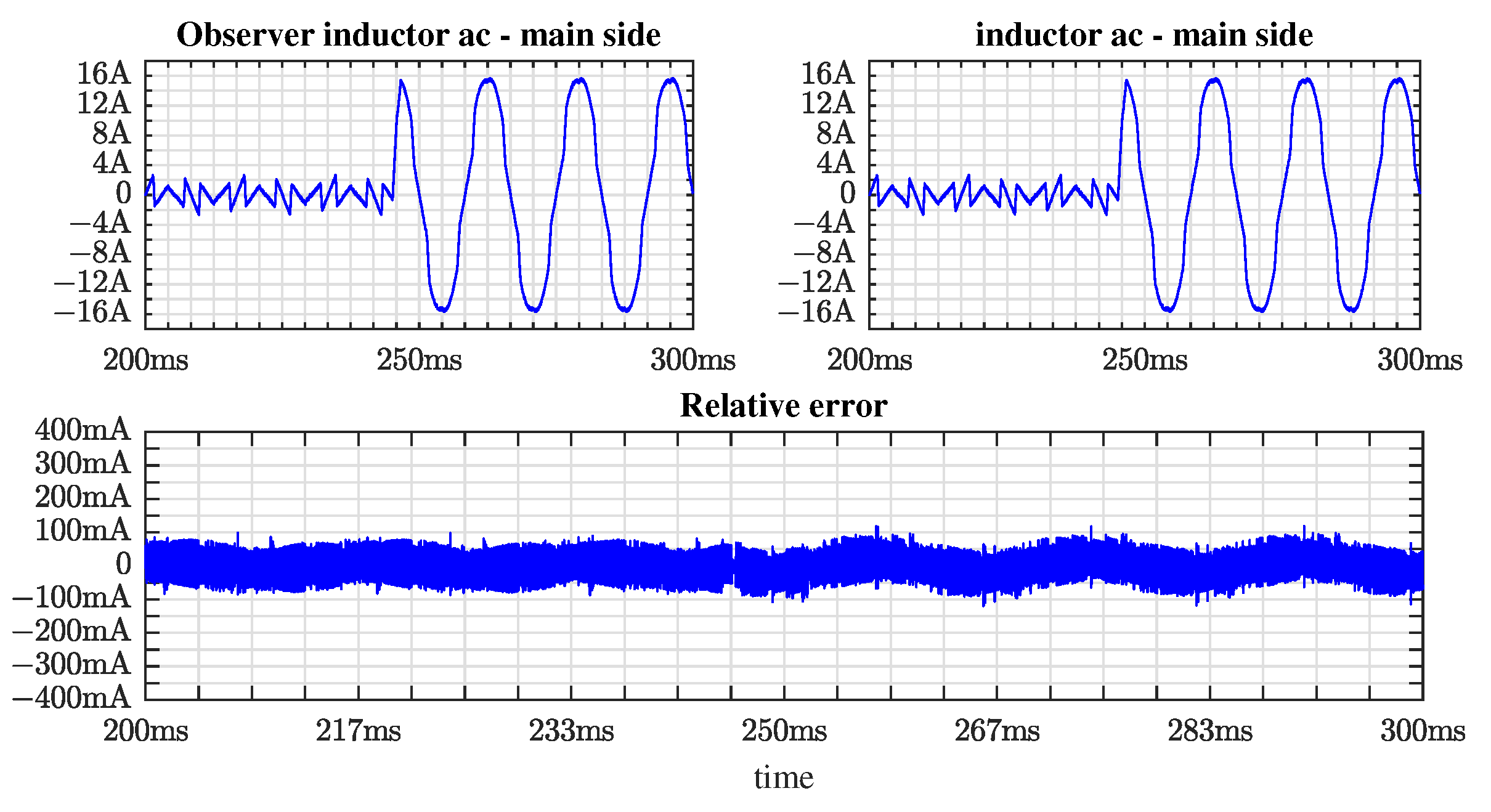
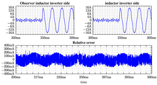
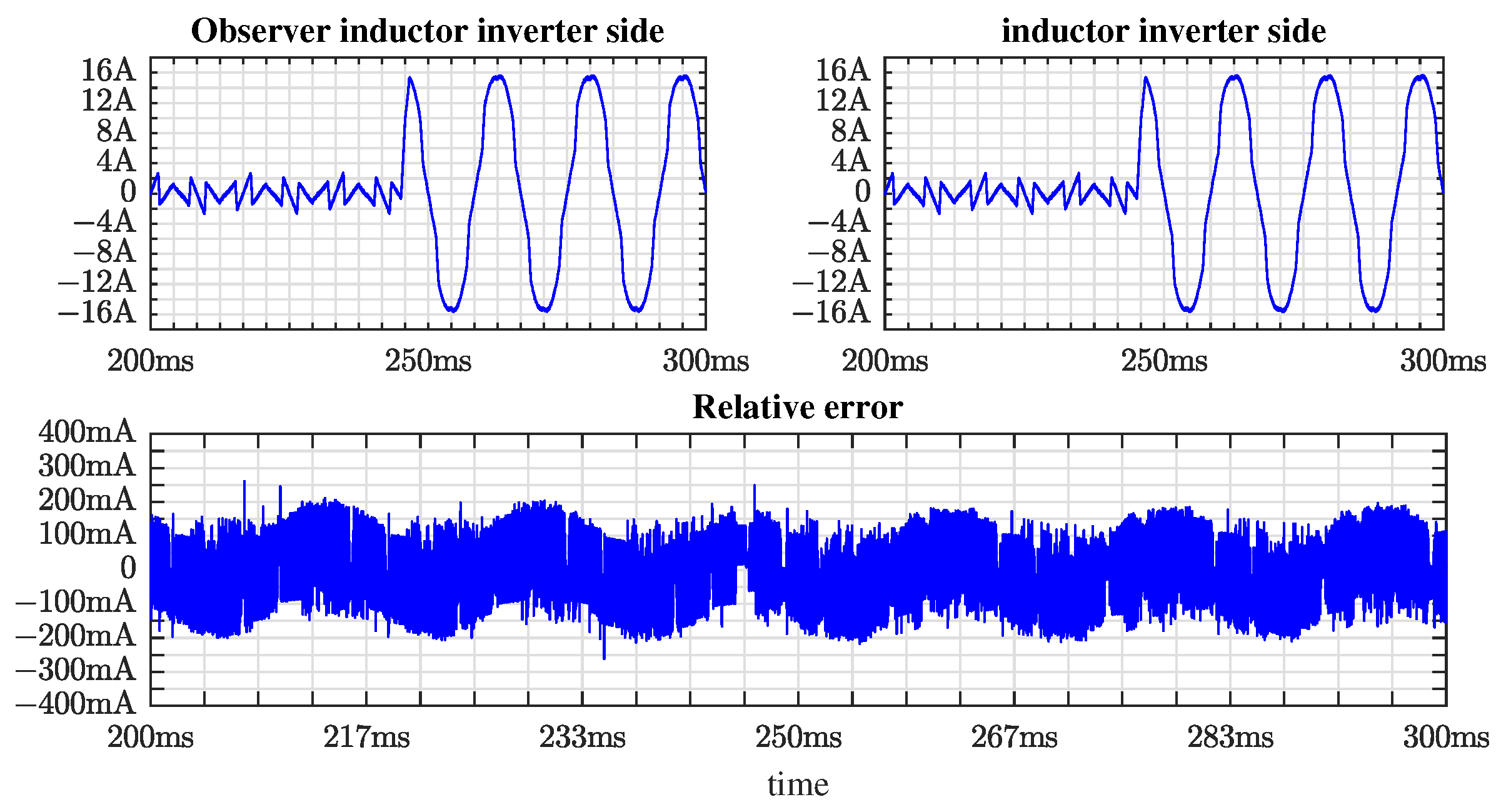
The performance results of the current signals observer is depicted in Figure 9 and Figure 10. Figures show the current observer in the inverter-side inductance against the current delivered by the inverter. Error deviation is presented at the bottom of the same figure. An advantage to using current signal observers are the unnecessarily hall-effect current sensors application. As above mentioned, when the number of sensors is reduced the system control scheme avoids sensor faults, hence reliability is improved as well as the resilience of the control scheme.
Figure 9.
Current waveforms: Observer inductor ac-main side, inductor ac-main side, and relative observer error.
Figure 10.
Current waveforms: Observer inductor inverter side, inductor inverter side, and relative observer error.
Figure 9 shows the current signal calculated by the observer. This signal corresponds to inverter-side inductor and it is compared against the current measured over the inverter-side inductor. To point out the performance of the current signal observer the relative error was calculated as presented at the bottom of the same figure.
Such as mentioned before, the current signal observer was implemented to calculate the circulating currents in the filter inductors. The signals of the current signal observer, as well as grid-side inductor current is depicted in Figure 10. finally, at the bottom of the figure the relative error is presented.
On the second hand, the next set of simulations results are related to implementing a linear load, strongly capacitive, connected at the common connection point in joint with the nonlinear load. In this result, the power electronics converter with the control scheme is tested with harmonics and capacitive power factor at the fundamental frequency component.
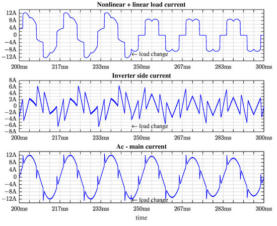
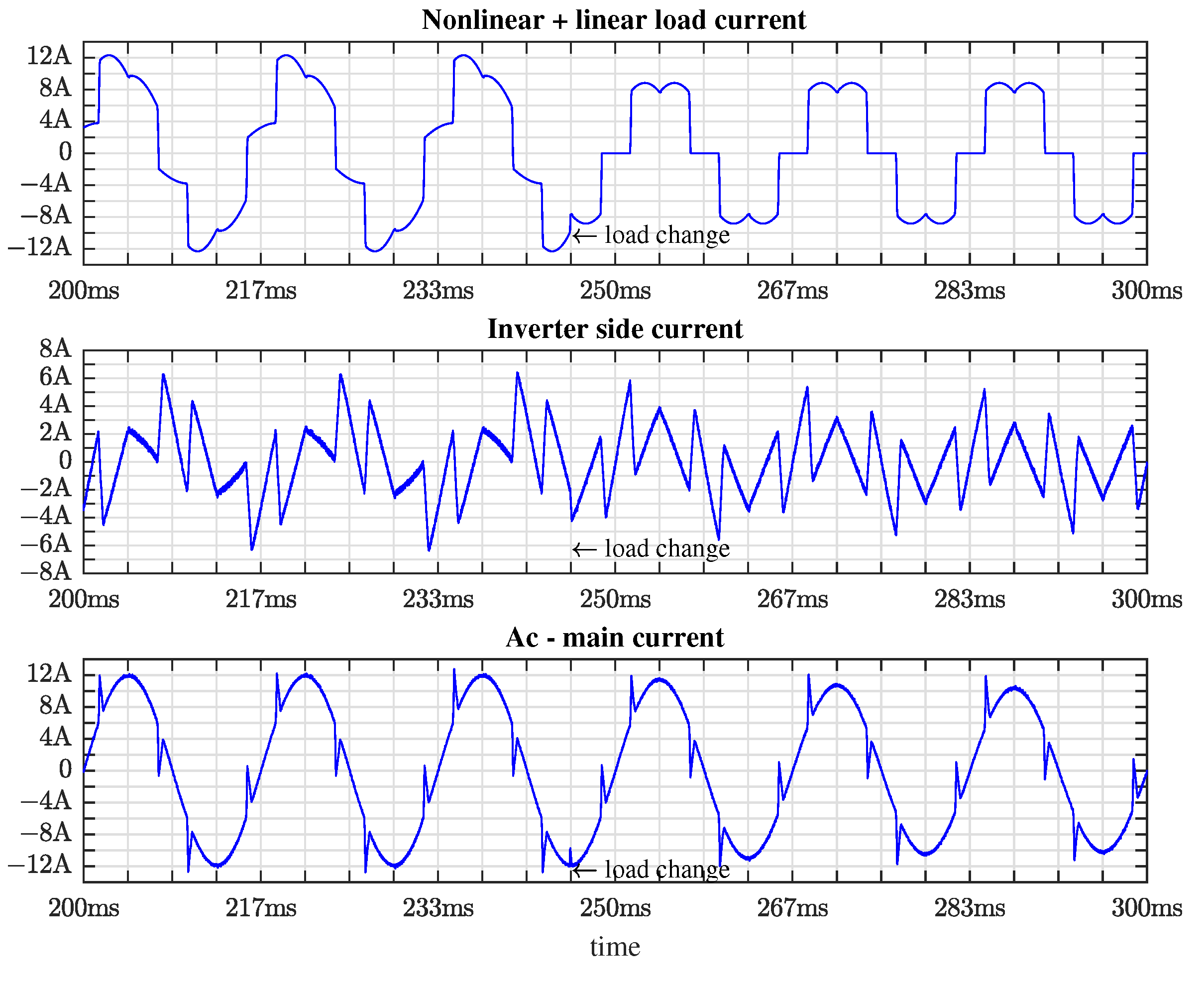
Figure 11 shows the results when a capacitive load is connected in joint with a nonlinear load. At the beginning of the simulation, the pair of linear and nonlinear load are supplied by AC-main, at approximately 246 ms the linear load is off, and only the nonlinear is connected at the AC-main. At this time, the power converter is functioning as the above commented.
Figure 11.
Main waveforms in power converter: from top to bottom, nonlinear + linear load current, inverter side current (compensation current), ac-main current (compensated current).
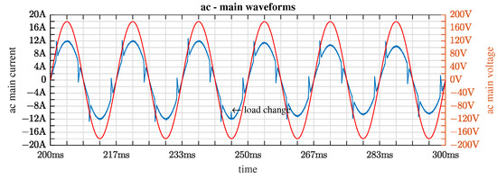
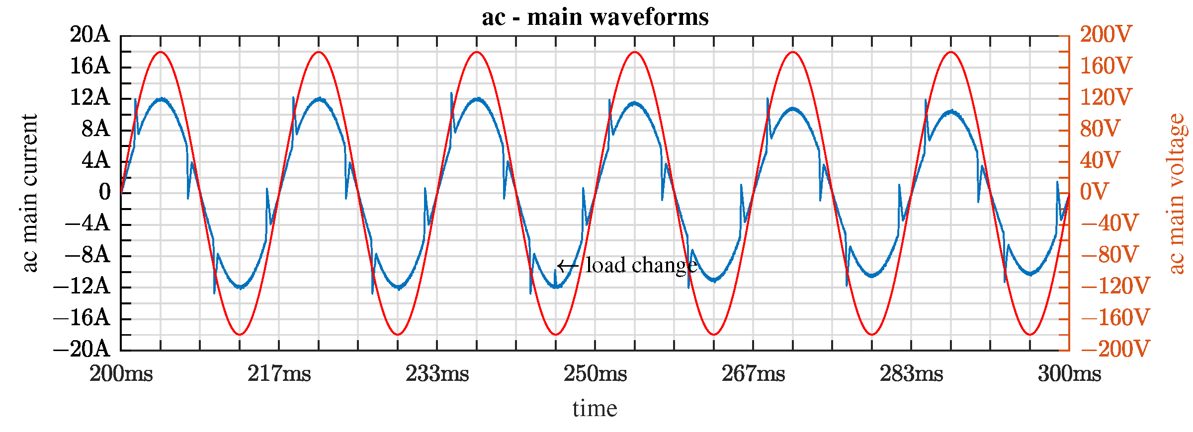
Along the total run-time simulation, the power factor at the ac-main is near one. In Figure 12 the AC-main current and the voltage are presented. As can be expected, the ac current and AC-main voltage are in-phase. Notice that, it is important to point out that the control scheme is adequate to harmonic compensation, active power and reactive power compensation.
Figure 12.
Ac-main electrical waveforms: current (blue) and voltage (red).
Table 2 presents the numerical results related to THD, before the filtering function is applied, and after, when the power converter acts as shunt-active filter. Notice that, the results presented in the same table, the load contains a three-phase current unbalanced. It is important to point out so the control law as well as the power converter has the capability to compensate unbalance load demand.
Table 2.
Performance results.
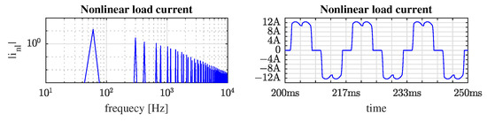
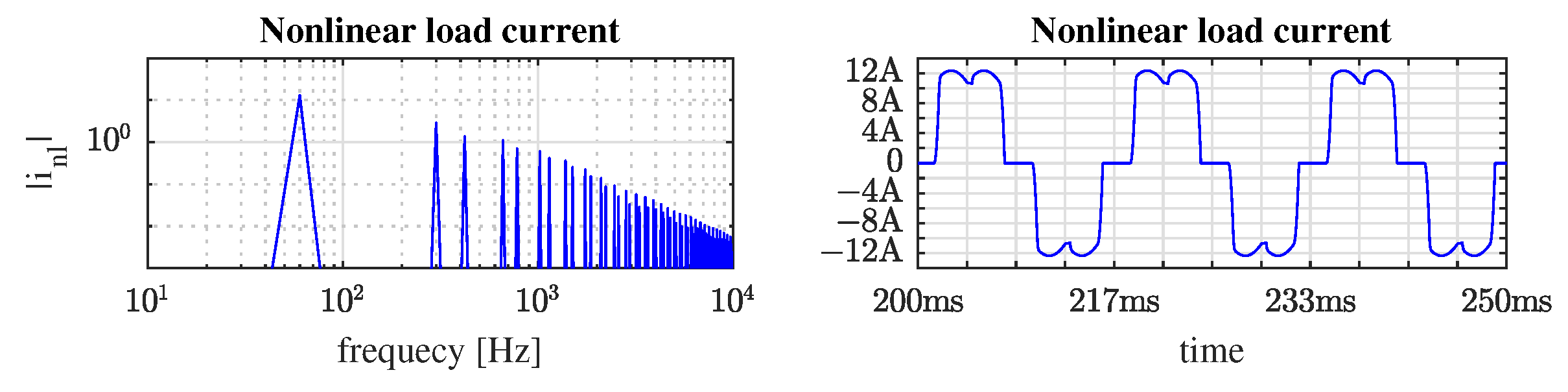
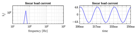
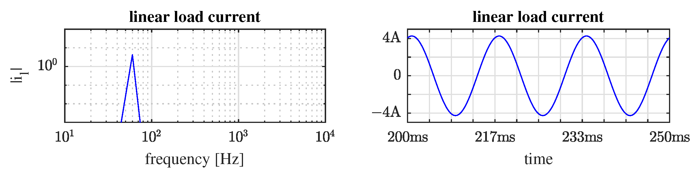
Figure 13 shows the frequency spectrum and the nonlinear current signal, Figure 14 illustrates the capacitive linear current signal. As can be seen, the spectrum-frequency of the current signals with harmonic free.
Figure 13.
Nonlinear load current: FFT results and waveform.
Figure 14.
Linear load current: FFT results and waveform.
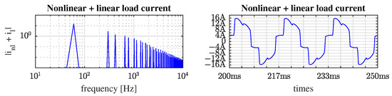
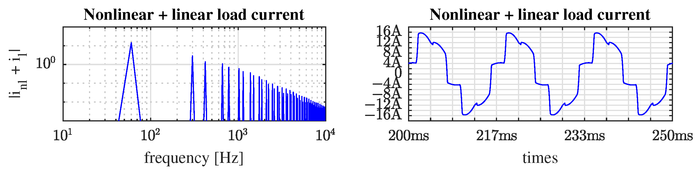
The total current demanded by the linear plus nonlinear load is depicted in Figure 15. Notice that, in same figure, the power factor is strongly capacitive.
Figure 15.
Nonlinear plus linear load current: FFT results and waveform.
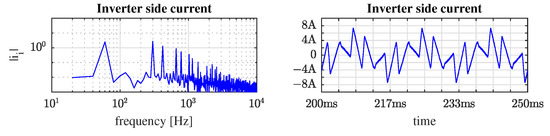
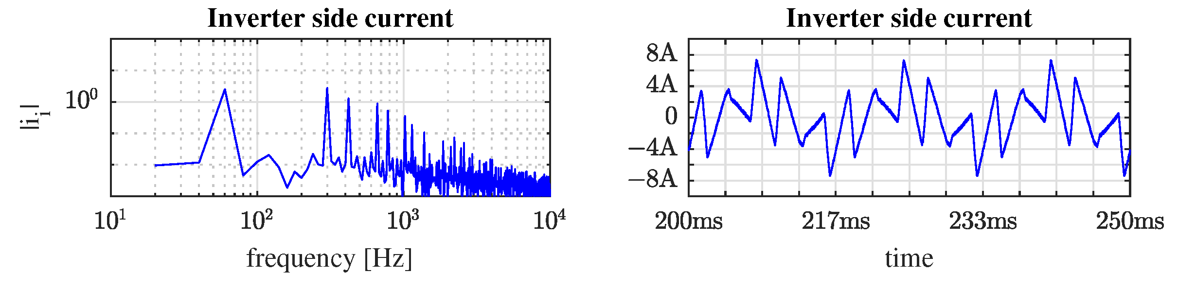
Reference signal produced by the electronic power converter acting as shunt active power filter is shown in Figure 16. The spectrum frequency shows the all harmonics components used to compensate the non linear load harmonics.
Figure 16.
Inverter side current (compensation current): FFT results and waveform.
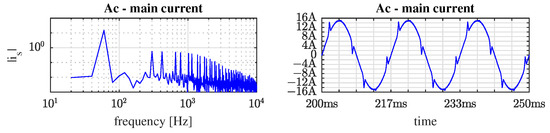
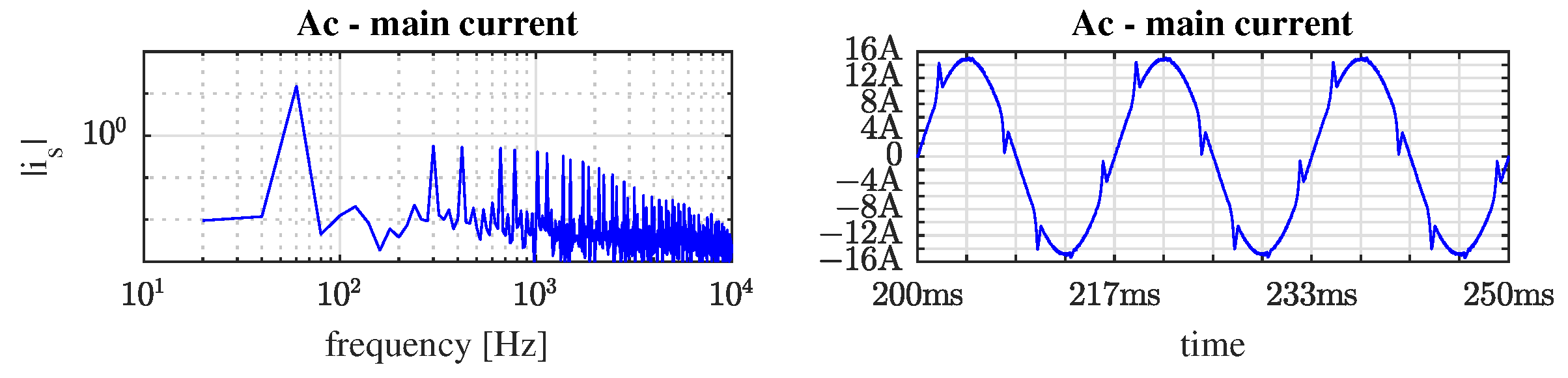
Finally, the ac-main current is presented in Figure 17. The spectrum frequency shows the harmonics diminished components.
Figure 17.
Ac-main current (compensated current): FFT results and waveform.
The proposed system achieves a significant THD compensation that complies with the STD-IEEE 519-2014 recommendation. To highlight the relevance of the results got in this work, a comparison of the reduction of the THD with similar researches is given in Table 3. Can be noted that the THD with active filter is similar in the compared works, however, the THD without active filter is greater in this study, then the proposed system compares favorably against all of them.
Table 3.
Results comparison.
5. Conclusions
This article proposes a sliding mode control scheme based on an immersion and invariance observer, which was designed and tested in simulation under different non-linear loads on a three-phase inverter connected to the grid through an LCL filter. The use of the observer eliminated the need to measure the currents of the inductors, which in practice is an advantage since it reduces costs and also eliminates potential sources of noise. This control strategy meets expectations, achieving small tracking errors and fast response times, reaching a stationary state in less than 50 milliseconds against abrupt load changes. The tracking performed by the control scheme significantly reduced the ac main current THD compared to the load current THD and maintain it below the recommended by the STD-IEEE 519-2014. It is important to clarify that the practical implementation is a challenge, since the observer I&I required a gain of 106 to obtain the estimation error and convergence time presented. Using numerical float-point representation to calculate numerically the proposed control scheme, the challenge could be affronted.
Author Contributions
All authors contributed to the conceptualization, experimental validation and writing-review & editing. All authors have read and agreed to the published version of the manuscript.
Funding
This research received no external funding.
Institutional Review Board Statement
Not applicable.
Informed Consent Statement
Not applicable.
Data Availability Statement
Not applicable.
Conflicts of Interest
The authors declare no conflict of interest.
References
- International Energy Agency. Renewables 2018: Analysis and Forecasts to 2O23; Market Report Series; IEA: Paris, France, 2018; Available online: https://www.iea.org/reports/renewables-2018 (accessed on 10 January 2021).
- El Ghaly, A.; Tarnini, M.; Moubayed, N.; Chahine, K. A Filter-Less Time-Domain Method for Reference Signal Extraction in Shunt Active Power Filters. Energies 2022, 15, 5568. [Google Scholar] [CrossRef] [Scilit]
- Nicolae, P.M.; Nicolae, I.D.; Nicolae, M.S. Some Considerations Regarding the Measurement of the Compensation Efficiency in Three-Phase Systems. Energies 2022, 15, 5004. [Google Scholar] [CrossRef] [Scilit]
- Pichan, M.; Seyyedhosseini, M.; Hafezi, H. A New DeadBeat-Based Direct Power Control of Shunt Active Power Filter With Digital Implementation Delay Compensation. IEEE Access 2022, 10, 72866–72878. [Google Scholar] [CrossRef] [Scilit]
- Li, P.; Huo, L.; Guo, Y.; An, G.; Guo, X.; Li, Z.; Sun, H. Modulation and Control Strategy of 3CH4 Combined Current Source Grid-Connected Inverter. Energies 2022, 15, 4219. [Google Scholar] [CrossRef] [Scilit]
- Shieh, J.J.; Hwu, K.I.; Li, Y.Y. A Single-Voltage-Source Class-D Boost Multi-Level Inverter with Self-Balanced Capacitors. Energies 2022, 15, 4082. [Google Scholar] [CrossRef] [Scilit]
- Desai, A.A.; Mikkili, S.; Senjyu, T. Novel H6 Transformerless Inverter for Grid Connected Photovoltaic System to Reduce the Conduction Loss and Enhance Efficiency. Energies 2022, 15, 3789. [Google Scholar] [CrossRef] [Scilit]
- Singh, A.; Parida, S. A review on distributed generation allocation and planning in deregulated electricity market. Renew. Sustain. Energy Rev. 2018, 82, 4132–4141. [Google Scholar] [CrossRef] [Scilit]
- Kalair, A.; Abas, N.; Kalair, A.; Saleem, Z.; Khan, N. Review of harmonic analysis, modeling and mitigation techniques. Renew. Sustain. Energy Rev. 2017, 78, 1152–1187. [Google Scholar] [CrossRef] [Scilit]
- Kharrazi, A.; Sreeram, V.; Mishra, Y. Assessment techniques of the impact of grid-tied rooftop photovoltaic generation on the power quality of low voltage distribution network—A review. Renew. Sustain. Energy Rev. 2020, 120, 109643. [Google Scholar] [CrossRef] [Scilit]
- Basso, T.; DeBlasio, R. IEEE P1547-series of standards for interconnection. In Proceedings of the 2003 IEEE PES Transmission and Distribution Conference and Exposition (IEEE Cat. No.03CH37495), Dallas, TX, USA, 7–12 September 2003; Volume 2, pp. 556–561. [Google Scholar] [CrossRef] [Scilit]
- Khosravi, N.; Abdolmohammadi, H.; Bagheri, S.; Miveh, M. Improvement of harmonic conditions in the AC/DC microgrids with the presence of filter compensation modules. Renew. Sustain. Energy Rev. 2021, 143, 110898. [Google Scholar] [CrossRef] [Scilit]
- Li, D.; Wang, T.; Pan, W.; Ding, X.; Gong, J. A comprehensive review of improving power quality using active power filters. Electr. Power Syst. Res. 2021, 199, 107389. [Google Scholar] [CrossRef] [Scilit]
- Gusman, L.; Pereira, H.; Callegari, J.; Cupertino, A. Design for reliability of multifunctional PV inverters used in industrial power factor regulation. Int. J. Electr. Power Energy Syst. 2020, 119, 105932. [Google Scholar] [CrossRef] [Scilit]
- Ravinder, K.; Bansal, H.O. Investigations on shunt active power filter in a PV-wind-FC based hybrid renewable energy system to improve power quality using hardware-in-the-loop testing platform. Electr. Power Syst. Res. 2019, 177, 105957. [Google Scholar] [CrossRef] [Scilit]
- Kashif, M.; Hossain, M.; Zhuo, F.; Gautam, S. Design and implementation of a three-level active power filter for harmonic and reactive power compensation. Electr. Power Syst. Res. 2018, 165, 144–156. [Google Scholar] [CrossRef] [Scilit]
- Souza, R.R.; Moreira, A.B.; Barros, T.A.; Ruppert, E. A proposal for a wind system equipped with a doubly fed induction generator using the Conservative Power Theory for active filtering of harmonics currents. Electr. Power Syst. Res. 2018, 164, 167–177. [Google Scholar] [CrossRef] [Scilit]
- Sahli, A.; Krim, F.; Laib, A.; Talbi, B. Model predictive control for single phase active power filter using modified packed U-cell (MPUC5) converter. Electr. Power Syst. Res. 2020, 180, 106139. [Google Scholar] [CrossRef] [Scilit]
- Kryonidis, G.C.; Kontis, E.O.; Papadopoulos, T.A.; Pippi, K.D.; Nousdilis, A.I.; Barzegkar-Ntovom, G.A.; Boubaris, A.D.; Papanikolaou, N.P. Ancillary services in active distribution networks: A review of technological trends from operational and online analysis perspective. Renew. Sustain. Energy Rev. 2021, 147, 111198. [Google Scholar] [CrossRef] [Scilit]
- Ghosh, S.; Rahman, S.; Pipattanasomporn, M. Distribution Voltage Regulation Through Active Power Curtailment With PV Inverters and Solar Generation Forecasts. IEEE Trans. Sustain. Energy 2017, 8, 13–22. [Google Scholar] [CrossRef] [Scilit]
- Mai, T.T.; Haque, A.N.M.; Vergara, P.P.; Nguyen, P.H.; Pemen, G. Adaptive coordination of sequential droop control for PV inverters to mitigate voltage rise in PV-Rich LV distribution networks. Electr. Power Syst. Res. 2021, 192, 106931. [Google Scholar] [CrossRef] [Scilit]
- Hannan, M.A.; Ghani, Z.A.; Hoque, M.M.; Ker, P.J.; Hussain, A.; Mohamed, A. Fuzzy Logic Inverter Controller in Photovoltaic Applications: Issues and Recommendations. IEEE Access 2019, 7, 24934–24955. [Google Scholar] [CrossRef] [Scilit]
- Wang, Y.; Yang, Y.; Liang, R.; Geng, T.; Zhang, W. Adaptive Current Control for Grid-Connected Inverter with Dynamic Recurrent Fuzzy-Neural-Network. Energies 2022, 15, 4163. [Google Scholar] [CrossRef] [Scilit]
- Kumar, N.; Saha, T.K.; Dey, J. Sliding mode control, implementation and performance analysis of standalone PV fed dual inverter. Sol. Energy 2017, 155, 1178–1187. [Google Scholar] [CrossRef] [Scilit]
- Kumar, N.; Saha, T.K.; Dey, J. Sliding-Mode Control of PWM Dual Inverter-Based Grid-Connected PV System: Modeling and Performance Analysis. IEEE J. Emerg. Sel. Top. Power Electron. 2016, 4, 435–444. [Google Scholar] [CrossRef] [Scilit]
- Wai, R.J.; Wang, W.H. Grid-Connected Photovoltaic Generation System. IEEE Trans. Circuits Syst. I Regul. Pap. 2008, 55, 953–964. [Google Scholar] [CrossRef] [Scilit]
- Fernao Pires, V.; Martins, J.; Hao, C. Dual-inverter for grid-connected photovoltaic system: Modeling and sliding mode control. Sol. Energy 2012, 86, 2106–2115. [Google Scholar] [CrossRef] [Scilit]
- Hassine, I.M.B.; Naouar, M.W.; Mrabet-Bellaaj, N. Model Predictive-Sliding Mode Control for Three-Phase Grid-Connected Converters. IEEE Trans. Ind. Electron. 2017, 64, 1341–1349. [Google Scholar] [CrossRef] [Scilit]
- Tan, S.C.; Lai, Y.M.; Tse, C.K. General Design Issues of Sliding-Mode Controllers in DC-DC Converters. IEEE Trans. Ind. Electron. 2008, 55, 1160–1174. [Google Scholar] [CrossRef] [Scilit]
- Dhar, S.; Dash, P. A new backstepping finite time sliding mode control of grid connected PV system using multivariable dynamic VSC model. Int. J. Electr. Power Energy Syst. 2016, 82, 314–330. [Google Scholar] [CrossRef] [Scilit]
- Reveles-Miranda, M.; Sánchez-Florez, D.F.; Cruz-Chan, J.R.; Ordoñez López, E.E.; Flota-Bañuelos, M.; Pacheco-Catalán, D. The Control Scheme of the Multifunction Inverter for Power Factor Improvement. Energies 2018, 11, 1662. [Google Scholar] [CrossRef] [Scilit]
- Reveles-Miranda, M.; Flota-Bañuelos, M.; Chan-Puc, F.; Ramirez-Rivera, V.; Pacheco-Catalán, D. A Hybrid Control Technique for Harmonic Elimination, Power Factor Correction, and Night Operation of a Grid-Connected PV Inverter. IEEE J. Photovoltaics 2020, 10, 664–675. [Google Scholar] [CrossRef] [Scilit]
- Said-Romdhane, M.; Naouar, M.; Slama-Belkhodja, I.; Monmasson, E. Simple and systematic LCL filter design for three-phase grid-connected power converters. Math. Comput. Simul. 2015, 130, 181–193. [Google Scholar] [CrossRef] [Scilit]
- Normand-Cyrot, D.; Fossard, A.J. Nonlinear Systems: Modeling and Estimation; Springer Science & Business Media: Berlin, Germany, 1995. [Google Scholar]
- Hoon, Y.; Mohd Radzi, M.A.; Hassan, M.K.; Mailah, N.F. A Dual-Function Instantaneous Power Theory for Operation of Three-Level Neutral-Point-Clamped Inverter-Based Shunt Active Power Filter. Energies 2018, 11, 1592. [Google Scholar] [CrossRef] [Scilit]
- Ding, X.; Xue, R.; Zheng, T.; Kong, F.; Chen, Y. Robust Delay Compensation Strategy for LCL-Type Grid-Connected Inverter in Weak Grid. IEEE Access 2022, 10, 67639–67652. [Google Scholar] [CrossRef] [Scilit]
- Guzman, R.; de Vicuña, L.G.; Morales, J.; Castilla, M.; Miret, J. Model-Based Control for a Three-Phase Shunt Active Power Filter. IEEE Trans. Ind. Electron. 2016, 63, 3998–4007. [Google Scholar] [CrossRef] [Scilit]

Publisher’s Note: MDPI stays neutral with regard to jurisdictional claims in published maps and institutional affiliations. |
© 2022 by the authors. Licensee MDPI, Basel, Switzerland. This article is an open access article distributed under the terms and conditions of the Creative Commons Attribution (CC BY) license (https://creativecommons.org/licenses/by/4.0/).