


Abstract
This article describes the function of the tarsal complex as a constrained mechanism. The relationship between the interdependence of the motions of the tarsal joints and the special nature of tarsal joint function is explained, with emphasis on the midtarsal joint and its presumed two axes of motion.
In 1781, Petrus Camper, a Dutch professor of anatomy and surgery and a keen observer, published a small treatise on the ideal shoe. The work was written in Dutch, but translations in French and German appeared within a few years, while an English translation dates to the early nineteenth century [1]. Camper emphasized, among other things, the asymmetry of the human foot and the increase in the length of the foot during the stance phase of gait. He recommended that the shoe’s forepart have a rounded outline and that shoes be an inch longer than the measured foot length. He believed that neglect of these rules was the source of many foot problems. Camper’s fight against fashion and ignorance has not yet ended, as is evident from the challenge of podiatric medical care today.
Indeed, several aspects of the biomechanics of the intratarsal motions are still poorly understood. Most descriptions and functional anatomical representations of the foot do not—or at best only partially— allow for two essential structural and functional features of the tarsal joints.
The first feature is position-dependent congruence and incongruence. The articular facets of several tarsal joints fit closely together in only one position of the joint; any subsequent motion leads to a partial loss of contact between them. The second feature is the interdependence of the motions occurring in the tarsal joints: immobilization of one joint limits the mobility of the others.
Position-Dependent Congruence and Motion-Related Partial Loss of Contact
The articular surfaces of many human joints seem to maintain full contact during their complete range of motion, even when the articulating surface areas differ considerably. Such joints are often compared to such axisymmetric rotating linkages as hinges or ball-and-socket joints. In contrast, other joints show a position-dependent contact; for them, such comparisons seem more difficult.
This position-dependent contact of the articular facets is a conspicuous feature of the posterior subtalar and calcaneocuboid joints. It is far less obvious, perhaps even absent, in the talonavicular and anterior talocalcaneal articulations. Position-dependent contact and motion-related partial loss of contact are two different states of the joint: the articular facets, despite their essentially complementary shape (one male and the other female), fit together perfectly in only one position. In all of the other joint positions, there is only partial contact between the articular surfaces.
Some joints, on the other hand, show a striking position-independent incongruence; the knee is an impressive example of this. In the knee, this incongruence is clearly related to the joint’s two modes of motion (flexion-extension and internal-external rotation). The following paragraphs will demonstrate that the temporary incongruence of the tarsal joints must also be understood in relation to their complex modes of motion. Why are position-dependent congruence and incongruence such relevant mechanical features? A closer look at the relationship between the motions of the joints and the geometry of the joints’ articular facets will make this clearer.
Two basic methods have long been used to identify the type of motion of any joint. In one method, the shape of the articular contact surfaces was considered to be the principal determinant of the motion, and the axis of rotation was derived from the curvatures of these contact surfaces. In the other method, the generated motion was used to define the corresponding axis of rotation.
The Contact Surfaces as the Principal Determinants of Axes of Rotation
In early discussions about the nature of the mechanics of the tarsal joints, the shape of the articular facets was emphasized as the principal mechanical determinant of the generated motion [2,3]. Apart from plane surfaces, only axisymmetric contact surfaces, one male and the other female (shaped as cylinders, cones, spheres, ellipsoids, or any other object that can be made with a milling machine), can maintain full contact during motion. Besides, only during full contact does the axis of rotation symmetry coincide with the axis of motion. Only then do the contact surfaces move purely by sliding over each other. However, the mechanical relationship between the shape of the contact surfaces and the motion occurring between them can be much more complex. This relationship depends not only on the shapes, or curvatures, of the contact surfaces but also on their contact behavior during motion. It is very difficult to use shape to predict the mode of the motion produced by non-axisymmetric curved surfaces. This is especially true if the contact surfaces combine translation with rolling, as in the human knee joint. In such cases, the curvatures alone give little information about the motion to be generated. Time and again, however, investigators have assumed underlying rotational symmetry for the shapes of the articular facets and thus tried to interpret tarsal motions as simple hinge motions; this approach can still be found in current literature [4]. In this approach, elasticity of cartilage was supposed to compensate for deviations from an idealized geometry. However, the small range of most of the intratarsal motions—in combination with their limited contact surfaces—raised great problems for an accurate analysis.
Analysis of the Generated Motion to Define Axes of Rotation
Other methods were based on an analysis of the generated motion; the aim was to define the axis of motion either with mechanical tools or through a combination of measurements and mathematical analysis. Mechanical tools included levers, pointers, and rods and eyes attached to any moving part. In this way, either the axis itself or the plane of motion perpendicular to this axis was determined [5,6,7]. Although these methods differ from the analysis of articular shape, the underlying assumption is still that the motion is a rotation about a fixed axis—in other words, a hinge or screw motion.
Mathematical procedures analyze the recorded and measured displacements of markers attached to the moving parts. These methods can be applied with a high degree of accuracy and do not presume a particular type of motion. The axes of motion are defined with respect to an orthogonal reference system, which is connected either to the unmoving surrounding world or to another link. These two kinds of definitions yield, respectively, “absolute” and “relative” axes of motion. Anatomists and clinicians use the latter when they discuss the axis of motion of a particular joint.
Furthermore, in a pure hinge joint, it is irrelevant whether the rotation of part A is defined with respect to part B or vice versa: both definitions will result in the same axis. Such a linkage is said to be kinematically reversible. However, an “impure hinge” joint, such as the knee, has a moving axis of motion; this can be presented as a bundle of successive axes of motion. Now, different bundles of subsequent motion axes will result from the two definitions of the axis: it matters whether the axis is defined by moving part A with respect to a fixed part B or by moving part B with respect to a fixed part A. Such linkages are kinematically irreversible. The same can be said of the complex motions between the tarsal bones. Although it is practically impossible to predict exactly how great the difference between the two kinds of axis bundles will be, they will have some general characteristics in common.
Interdependence of Tarsal Joint Motions
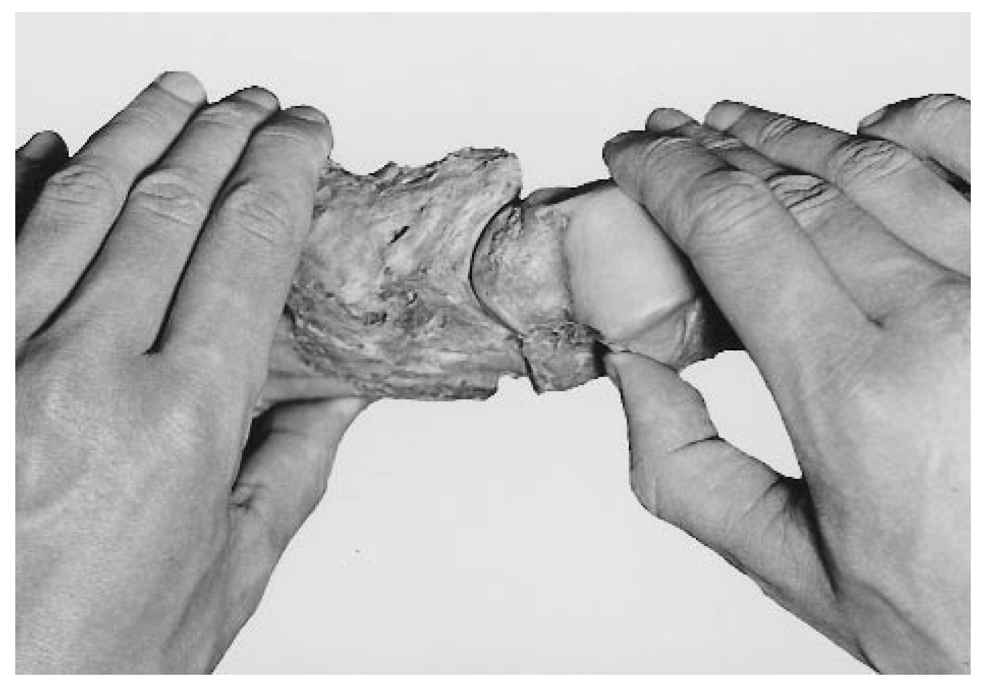
Interdependence of the tarsal motions is the other essential feature of the tarsal mechanism. It was already described by nineteenth-century anatomists, who experimented with a kind of arthrodesis of the subtalar joint in cadaver feet [2,3]. After such a procedure, they found mobility in the talonavicular and calcaneocuboid joints to be severely restricted. Modern clinical experience endorses these observations [4,8]. This phenomenon can also be demonstrated in a dissected foot exarticulated in the ankle joint (Figs. 1–3). In the illustrations presented here, the muscles have been removed in order to gain sufficient mobility in the joints, but all of the tarsal ligaments have been retained. Only the dorsal capsules of the talonavicular and calcaneocuboid joints have been resected to show what these joints do during the demonstrated maneuvers. The removal of these capsular parts had no effect on the nature of the joint’s motions.
Figure 1.
An osteoligamentous dissected specimen of the foot exarticulated at the ankle joint. The dorsal capsules of the talonavicular and calcaneocuboid joints have been removed. The foot is held in the neutral position corresponding with upright standing.
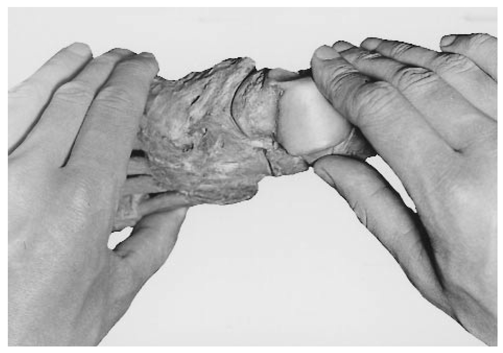
Figure 2.
The talus has been moved as it does in supination of the foot while the calcaneus, cuboid, and navicular are kept immobile. The talar head has left the navicular socket laterally, creating a wide gap at the medial side of the talonavicular joint.
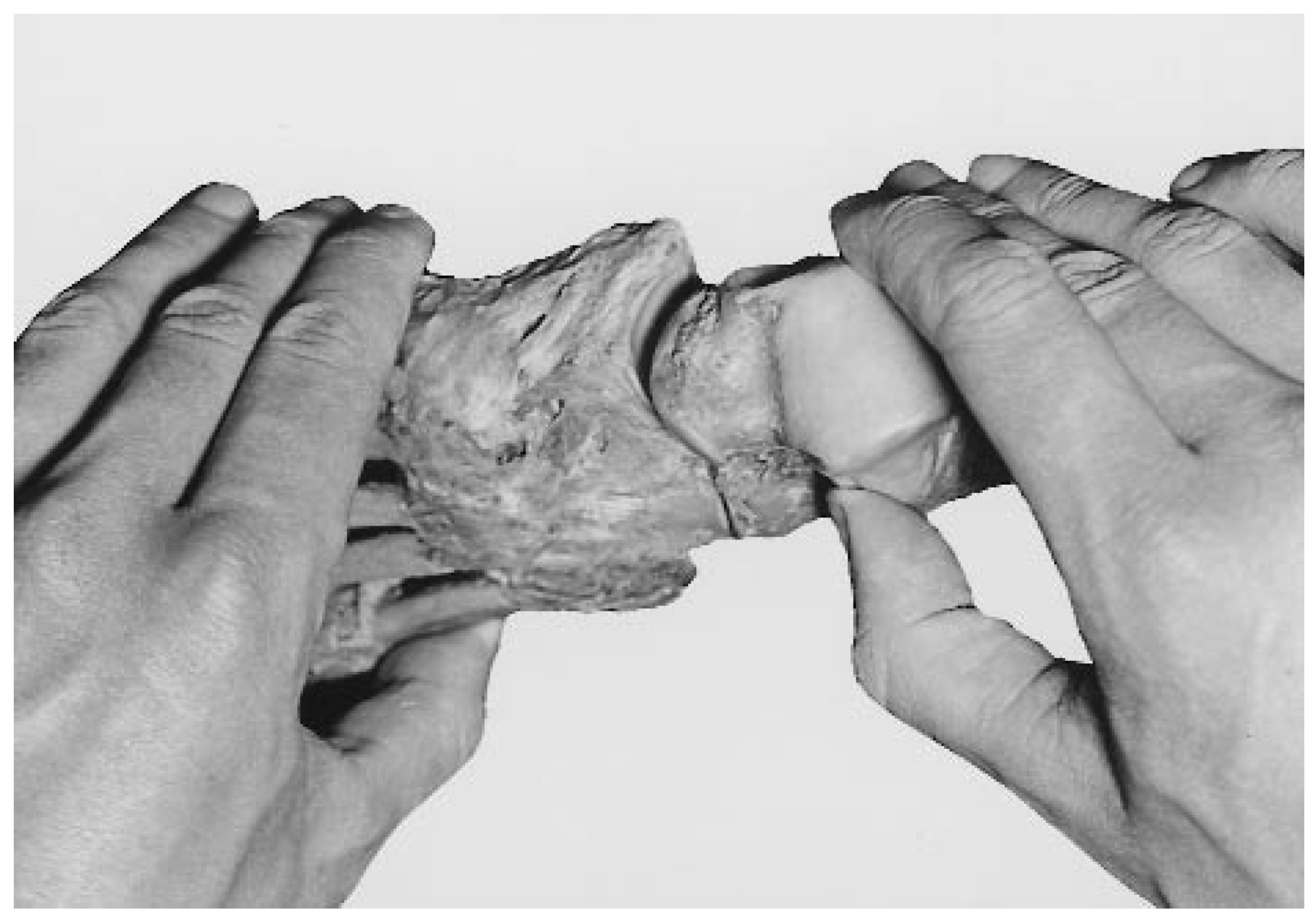
Figure 1 illustrates the position of the tarsal bones in stance. All of the joint facets, even the invisible ones, are in full contact with each other. When the talus is moved as in supination of the foot, it is guided by the talocalcaneal joint’s facets and the talocalcaneal ligaments in the sinus and canalis tarsi (Fig. 2). But the calcaneus, the cuboid, and the navicular are kept in their original positions with respect to one another. The effect is a wide gap in the talonavicular joint. The head of the talus has moved out of the navicular socket in a backward and lateral direction. This indicates that an accompanying motion of the cuboid and the navicular is required to maintain integrity of the talonavicular joint during supination.
When this accompanying motion in the calcaneocuboid joint is carried out and talonavicular contact is restored, it is the shape of the calcaneocuboid joint facets and the strong ligaments between the calcaneus, cuboid, and navicular that prescribe the produced motion (Fig. 3). Comparison of the stance position (Fig. 1) with the final position (Fig. 3) clearly shows the changes in position of the talar head, the navicular socket, the anterior part of the calcaneus, and the cuboid. In the intact foot, the motions demonstrated in Figure 2 and Figure 3 occur simultaneously.
Although this striking interdependence is well documented in the literature, few explanations have been proposed for it. Suggested explanations have included concurring and mutually compensating eccentric deviations of the talar head and the navicular during their hinge motions [2] and compensating translations along the screw axes of these bones [7]. However, the mechanical explanation should be sought in the existence of a closed kinematic chain in the tarsus.
Figure 3.
The wide talonavicular gap seen in Figure 2 has been closed again following a motion in the calcaneocuboid joint as prescribed by its kinematic constraints: the shape of its articular facets and the configuration of its ligaments.
The Tarsal Mechanism as a Closed Kinematic Chain
The tarsal bones together form an articulated ring of bones. The talus articulates with the calcaneus, the calcaneus with the cuboid, the cuboid with the navicular, and the navicular with the talus: a so-called closed kinematic chain with only one kinematic degree of freedom [9]. Under weightbearing conditions, this kinematic chain acts as a mechanism in engineering terms. If a motion is imposed upon one of the links, the other links are also forced to move. Because no muscle inserts on the talus, this bone needs other driving forces. Either the ankle mortise with a strong osteoligamentous grip on the talus or the other tarsal bones, which bear muscle insertions, can force the talus (and thereby the entire tarsal mechanism) into motion. This mechanical feature turns the tarsal mechanism into a stable, central part of the foot: a heavy-duty mechanism that can act reliably under accurate control.
If the motions in such a mechanism are three-dimensional—that is, if the motions do not occur in parallel planes—such a mechanism needs at least seven degrees of freedom distributed over its linkages. These could be seven simple hinges. Alternatively, if the mechanism has fewer linkages, some linkages must have more than one degree of freedom, such as occurs in a universal joint, a ball-andsocket joint, or “hinges” with a moving axis like the knee. In the latter case, if the linkages rotate about moving axes, the successive changes in direction and position of these axes will occur according to a complex and characteristic pattern.
It is obvious that the motions of the tarsal bones are essentially three-dimensional. And because the tarsal mechanism comprises only three real arthrodial joints—the subtalar joint, the talonavicular joint, and the calcaneocuboid joint (the cuboideonavicular joint being an amphiarthrosis with only very limited mobility)—the seven degrees of freedom could be distributed as two plus three plus two. If so, all of these tarsal joints will rotate about moving axes. It is also very likely that these simultaneous rotations will occur in a characteristic pattern. This pattern is prescribed by the kinematic constraints of the involved joints. These constraints are defined by 1) the shape of the involved joint facets, 2) the position of the joints with respect to one another, and 3) the kinematically determinant ligament fibers. With the possible exception of the talonavicular joint, motions about a moving axis are incompatible with axisymmetric articular facets. In the tarsal mechanism, therefore, the occurrence of moving axes is a mechanical consequence of the interdependence of tarsal motions, and position-dependent congruence (or motion-related contact loss) is the other side of motion interdependence.
Experimental Evidence
A thorough kinematic analysis of the tarsal motions has experimentally demonstrated the validity of these theoretical predictions [10,11]. This analysis was carried out on motions recorded and measured in a specimen comprising the lower leg and foot. All of the muscles were removed to obtain free mobility in the joints, but ligaments were kept intact. If such a specimen is placed upright in an experimental rig, its sole flat upon a supporting board and the tibial plateau vertically loaded with an appropriate weight, earlier observations that the foot arches do not sag in the absence of muscle action can be confirmed [12]. This is not due to an extraordinary stiffness of the preserved ligaments; a similar observation was made in fresh specimens. Under dynamic conditions, the strong plantar ligaments are well able to gird the arches. Applying an external rotation to the tibial plateau, the foot will supinate if a small block placed against the lateral foot border prevents outward rotation of the foot. The successive positions of the bones during supination were recorded on x-rays and measured. The results of the mathematical analysis of these measurements show that talocalcaneal, calcaneocuboid, and talonavicular motions occur about a number of successive and instantaneous motion axes; actually, these motion axes change their position and direction during the performed motion. These axes can be described as a bundle of stepwise operative axes; each bundle is characteristic for the tarsal joint concerned. All of these bundles have in common an oblique direction, more or less comparable with the obliquity of the “single” axis for supination and pronation of the foot so often described in the literature. However, these more or less conical-shaped bundles do not coincide.
In a series of experiments using ten anatomical specimens, the bundles that represented the successive talonavicular motion axes varied between a more or less circular outline and a clearly oval one. In a horizontal and vertical projection, the top angle varied from 1.8° to 29.4° and from 6.3° to 31.9°, respectively. For the talocalcaneal bundles, the projected top angles varied from 4.4° to 24.8° and from 2.8° to 26.3°, whereas for the calcaneocuboid bundles, the projected top angles varied from 5.9° to 65.6° and from 8.7° to 39.8°. Repeated calculations of such bundles yielded quite reproducible results. In these ten specimens, rotations were greatest in the talonavicular joint (mean, 43.1°; range, 29.9° to 50.7°) and smallest in the calcaneocuboid joint (mean, 15.8°; range, 8.8° to 25.3°), with values for the subtalar joint falling between the two foregoing series (mean, 23.6°; range, 15.8° to 30.0°). It is interesting that all of the talonavicular motion axes appeared to pass through a very small area, thus strongly resembling the behavior of a ball-and-socket joint. But what exactly can be observed in the tarsal joints themselves?
Observations on Supination in a Loaded Anatomical Specimen
Some aspects of the tarsal mechanism can be seen in observations of a specimen of lower leg and foot similar to the one used in the kinematic analysis. If the lower leg is rotated externally, the strong horizontal bundles of the talocrural ligaments force the talus to follow the lower leg in its external rotation, and the talar head turns laterally. The talus slides with its lateral side backward and upward along the posterior calcaneal facet of the subtalar joint. If the joint capsule has been partially opened, it can be seen that in the upper and most curved posterior part of the joint, the facets lose their contact and a wide gap occurs. Only in the less curved and oblique anterior part of the joint do the facets keep a firm contact. Another typical concurrent feature is a widening of the sinus tarsi, which can be seen not only in such a specimen but also in lateral x-rays of a living supinated foot.
Because the ankle mortise forces the talar trochlea to move in a horizontal plane, the talus will not undergo an eversion tilt while climbing upward in the subtalar joint. Instead, it is the calcaneus that is forced to carry out an inversion tilt under the talus, thus turning the heel into a varus position. This tilt is combined with an adduction and a slight dorsiflexion relative to the talus. Meanwhile, the cuboid not only follows this inversion tilt of the calcaneus but moves together with the navicular in inversion and adduction with respect to the calcaneus. The lateral border of the cuboid moves in a plantar direction against the slightly upward moving anterior part of the calcaneus. Total inversion of the cuboid is therefore greater than that of the calcaneus.
As in the subtalar joint, the facets of the calcaneocuboid joint partly lose their contact. This is clearly visible on lateral and dorsoplantar x-rays of the supinated specimen as well as in x-rays of the living foot. The effect of this set of motions is that the talonavicular joint moves upward and the medial arch is raised. Meanwhile, the navicular socket slides medially and backward over the laterally turning talar head (Fig. 3). However, this is a relative shift of the navicular with respect to the talus. The motion of the navicular relative to the ground is also an outward shift. It looks as if the talar head pulls the navicular upward and outward, thus enhancing the supination tilt of the navicular and cuboid already induced by the calcaneal tilt. As long as the medial part of the forefoot maintains its supporting function and keeps contact with the supporting surface, the first metatarsal bone must undergo a relative plantarflexion.
The result of all of these position changes is not only a raised medial arch but also an inwardly curved medial foot border. The medial vault has become deeper and higher as in a cavovarus configuration. Finally, these changes are reflected in an upward motion of the supported leg and body. This concurrent elevation of the body mass will tend to flatten the raised medial arch and bring the foot back into its neutral position. Muscular effort is needed to raise the body during this supination motion. The force of gravity has a pronation effect in the partly supinated foot. In the experiments, the moment required to achieve this external rotation in an anatomical specimen (fresh and embalmed) has been measured.10 This resulted in characteristic moment curves that could be related to structural characteristics of the foot skeleton. In most feet, there was an initial increase of the required moment until a transient maximum was reached; then the moment decreased to a minimum and, finally, increased steeply to bring the motion to an end. The structural characteristics of the foot could be expressed as a so-called tarsal index. Flatter feet had a higher tarsal index and a more pronounced transient moment maximum whereas more highly arched feet in general had a lower index and almost no transient maximum in the moment curve. Although this suggested that feet with lower indices might be more prone to an inversion trauma, a recent clinical study offered no confirmation of such a relationship [13].
The Problem of the Two-Axes Model of the Midtarsal Joint
In the recent literature, the interdependence of tarsal motions is recognized. On the other hand, researchers still seem to cling to the idea that the midtarsal joint comprises two (simple) hinges that cooperate either in a state of free mobility or in a blocked condition [4,14,15,16]. In the pronated/everted position, their axes are supposed to run parallel to each other, and a certain free mobility as a concomitant motion in both joints is supposed to be possible. In the neutral and supinated/inverted foot, characterized by increasingly divergent axes, free motions are supposed to become more and more restricted. In this view, the foot is converted from a flexible adaptive structure into a rigid lever. Indeed, this idea of variable mobility has even been applied to the entire subtalar complex.4
The assumption that mobility is increased by changing the divergent running axes into parallel positions might be based on the idea that the positions with divergent and parallel axes correspond to conditions of spatial and planar motions, respectively. This, however, is questionable.
In the first place, tarsal motions are always spatial motions, as can be concluded from the kinematic analysis [10,11]. Second, a combined rotation about both axes (like two parallel open doors of a cupboard) would assume a concurrent shift between the two rotating bodies: that is, between the navicular and the cuboid. The strong connection between these two bones makes such a parallel shift very unlikely. Finally, divergent running axes are quite compatible with mobility as long as these axes can change direction or position during the performed motions, as is shown in the results of the kinematic analysis. A slight plantarflexion of the forefoot in the talonavicular and calcaneocuboid joints has been described as a kind of clawing in stance [17]. This could be explained by the parallel direction of the main curvatures of the joint surfaces involved, not the axes of motion.
The above-mentioned problems are conceptual. However, methodologic problems also exist. Determination of rotation axes for the calcaneocuboid joint by means of rather crude mechanical methods is problematic because of the relatively small ranges of motion in this joint. Even if the measurements are carried out with great care, they can hardly be expected to yield more than an approximation of the general or dominant direction of the axis of motion. It therefore remains doubtful whether a relationship can be found between these axes and the successive instantaneous helical axes that are calculated with advanced mathematical methods after very accurate recordings and measurements of the motions concerned.
Because of the complex mechanical relationships between the tarsal motions and between these and other complex motions in the tarsometatarsal joints, the use of axes of rotation as tools for a reliable quantitative clinical evaluation of foot function has no firm basis so far. It may be that in the future noninvasive methods combined with quantitative image-processing techniques will offer such tools. The first impressive steps toward such methods have been reported in the literature [18].
References
- CAMPER, P. “On the Best Form of Shoe,” in The Foot and Its Covering,; Dowie, J, Ed.; R Hardwike: London, 1861. [Google Scholar]
- HENKE, W. Die bewegungen des fuszes am sprungbein. Zeitschr rat Med, NS 7, 225, 1855.
- DÖNTIZ A: Die Mechanik der Fuszwurzel [dissertation]. University of Berlin, Berlin, 1903.
- JAHSS, MH. “The Subtalar Complex,” in Disorders of the Foot and Ankle, 2nd Ed; Jahss, MH, Ed.; WB Saunders: Philadelphia, 1991; Vol 2, p. 1333. [Google Scholar]
- MANTER JT: Movements of the subtalar and transverse tarsal joints. Anat Rec 1941, 80, 397. [CrossRef] [Scilit]
- HICKS JH: The mechanics of the foot: I. the joints. J Anat Lond 1953, 87, 345.
- INMAN VT: The Joints of the Ankle; Williams & Wilkins: Baltimore, 1976.
- OUZOUNIAN, TJ; KLEIGER, B. “Arthrodesis in the Foot and Ankle,” in Disorders of the Foot and Ankle, 2nd Ed; Jahss, MH, Ed.; WB Saunders: Philadelphia, 1991; Vol 3, p. 2614. [Google Scholar]
- HARTENBERG, RS; DENAVIT, J. Kinematic Synthesis of Linkages; McGraw-Hill: New York, 1964. [Google Scholar]
- BENINK, RJ. The constraint-mechanism of the human tarsus: a roentgenological experimental study. Acta Orthop Scand Suppl 1985, 215, 1. [Google Scholar] [CrossRef] [Scilit] [PubMed]
- VAN LANGELAAN EJ: A kinematical analysis of the tarsal joints: an X-ray photogrammetric study. Acta Orthop Scand Suppl 1983, 204, 1.
- JONES RL: The human foot. Am J Anat 1941, 68, 1.
- LOUWERENS, JWK; GINAI, AZ; VAN LINGE, B. ET AL: Chronic instability of the foot and foot geometry: a radiographic study. Foot 1996, 6, 13. [Google Scholar] [CrossRef] [Scilit]
- BEVANS, JS. Biomechanics: a review of foot function in gait. Foot 1992, 2, 79. [Google Scholar] [CrossRef] [Scilit]
- MANN R: “Overview of Foot and Ankle Biomechanics,” in Disorders of the Foot and Ankle, 2nd Ed; Jahss, MH, Ed.; WB Saunders: Philadelphia, 1991; Vol 1, p. 385. [Google Scholar]
- NESTER, CJ. Rearfoot complex: a review of its interdependent components, axis orientation and functional model. Foot 1997, 7, 86. [Google Scholar] [CrossRef] [Scilit]
- AMBAGTSHEER, JB. The function of the muscles of the lower leg in relation to movements of the tarsus. Acta Orthop Scand Suppl 1978, 172, 1. [Google Scholar] [CrossRef] [Scilit] [PubMed]
- HIRSCH, BE; UDUPA, JK; SAMARASEKERA, S. New method of studying joint kinematics from three-dimensional reconstructions of MRI data. JAPMA 1996, 86, 4. [Google Scholar] [CrossRef] [Scilit] [PubMed]
© 2000 American Podiatric Medical Association