


Abstract
Background: The use of total first metatarsophalangeal joint (MPJ) arthroplasty to treat patients in which the pain, due to a pathological joint, has not been relieved with a conservative method or for which the disease or disorder is at an advanced stage, is popular. Although meta-analysis of clinical results indicates that this surgical option is efficacious, there are problems with implant failure due to wear of the components. Although there is a plethora of designs of this type of implant in clinical use, there are no literature reports on total first MPJ simulators, which may be used to evaluate, for example, the wear rate of a total first MPJ implant. Methods: We designed such a simulator, guided by the biomechanics of the joint. Thus, for example, the implant under test will be articulated at least 40° dorsiflexion, under a 600 N loading, at 1 Hz. Furthermore, the testing stations will be configured to allow testing of any type of first MPJ implant. We also performed a finite element analysis (FEA) study of a model of an articulating station, subjected to a quasi-static load of 1200 N. Results: For an articulating station, 1) the highest von Mises stress occurred at the implant-fixture interface; and 2), for the other parts, the minimum factor of safety, against elastic failure, is approximately 9. Conclusions: The designed joint simulator is mechanically sound and may be used for wear testing of any type of first MPJ implant.
The first metatarsophalangeal joint (MPJ) is subject to a number of pathologies, such as osteoarthritis, rheumatoid arthritis, hallux rigidus, hallux valgus, gout, neuromuscular disorders, congenital defects, and trauma.[1] When the pain caused by any of these pathologies is severe and refractory to conservative treatments, such as ingestion of nonsteroidal anti-inflammatory medication and use of orthotic devices,[2] there are a number of surgical treatment options, among which are arthrodesis,[3,4] metatarsal osteotomy,[5] excision-type (Keller’s) arthroplasty with a biological spacer,[6] joint distraction,[7] and joint arthroplasty.[8,9] Arthrodesis and total first MPJ implant arthroplasty have emerged as the two most popular. Drawbacks of arthrodesis include loss of motion at the joint, significant reduction in step length, and decreased ankle plantarflexion at toe-off.[3] There is a large assortment of commercially available total first MPJ implants and they may be grouped on the basis of 1) materials used for fabrication (an elastomer (such as polysiloxane), a metal (such as Ti alloy, Co-Cr alloy, or stainless steel, with or without a ultra-high-molecular-weight polyethylene (UHMWPE) insert), and a ceramic (such as ZrO2)); or 2) design (unconstrained and constrained).
Although there is evidence of benefits of total first MPJ implant arthroplasty,[10] the results of head-to-head clinical comparisons of arthrodesis and total first MPJ arthroplasty show better functional outcomes with the former procedure.[11–13] These better outcomes are a consequence of the many failure modes suffered by a first MPJ implant, the most severe of which is wear.[14–17] Thus, improvement in the wear resistance of a first MPJ implant may contribute to it becoming a credible competitor to arthrodesis. A crucial first step is to develop a first MPJ simulator in which in vitro wear tests on total first MPJ implants may be conducted. There are no literature reports on this issue.
The purpose of the present work was to design such a joint simulator and to perform stress analysis of one of its parts, namely, an articulating station.
Design Details
The design of the joint simulator was guided by the biomechanics of the normal MPJ, namely, 1) the magnitudes of the various motions of the joint and the force acting on the joint during normal activities, in particular, during gait; and 2) the frequency during normal gait. Thus, during a test using the designed simulator 1) the implant would be subjected to a dorsiflexion of at least 40° (note that this angle is defined with respect to the plantar plane of the foot of an individual who has the implant)[18,19]; and 2) at a given dorsiflexion angle, a loading cycle (0–600 N[20,21] at a frequency of 1 Hz[22]) would be applied to the implant. Furthermore, the geometrical configuration and size of the testing stations must accommodate any type of implant.
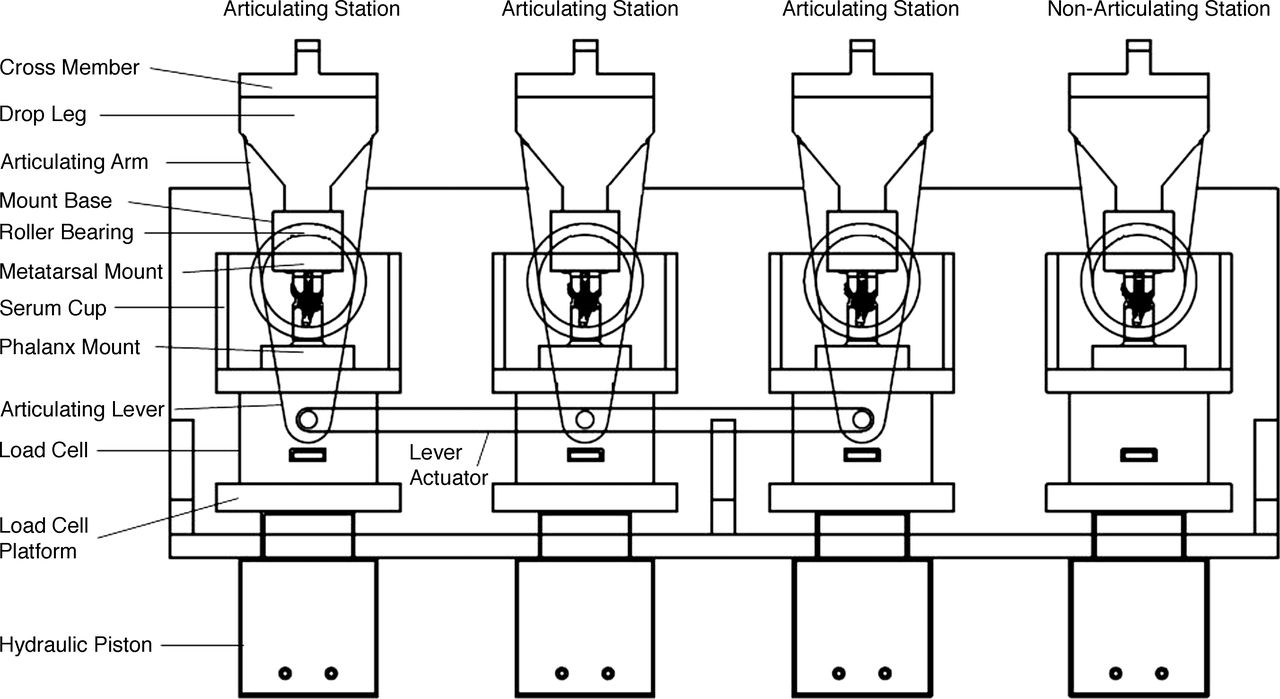
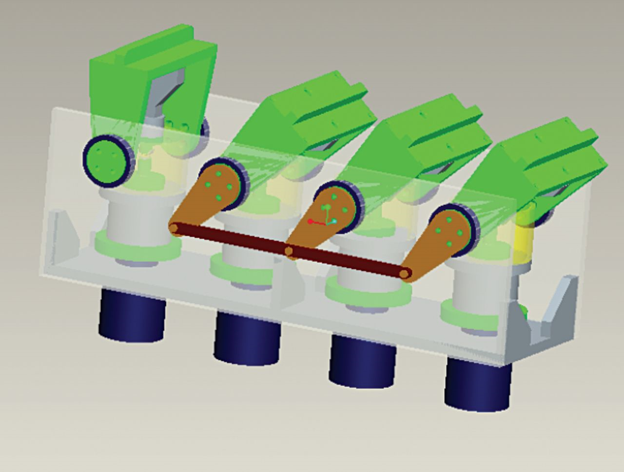
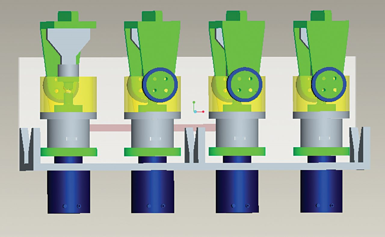
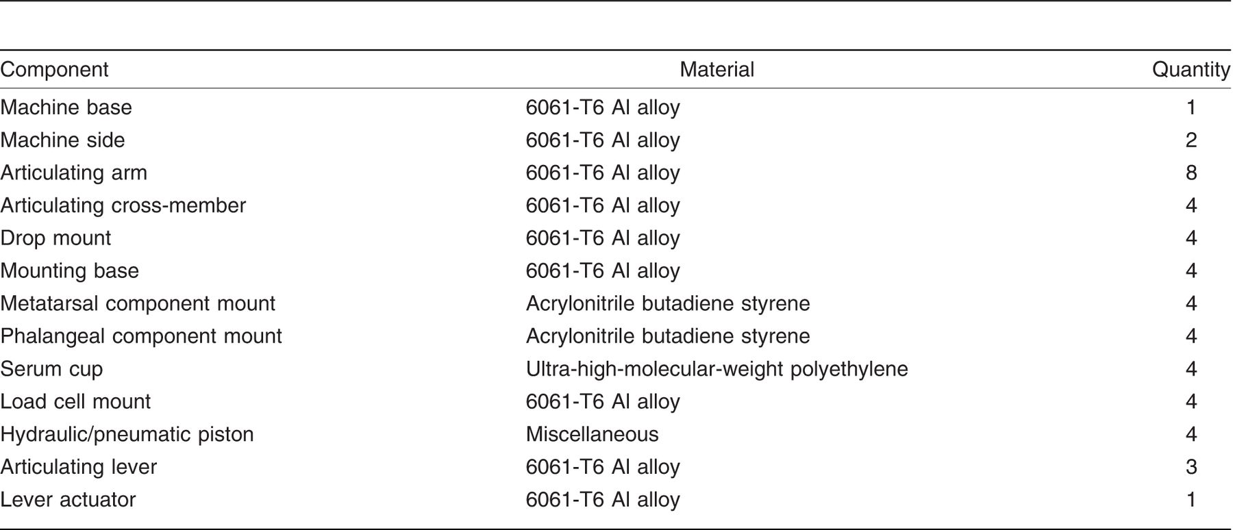
A schematic drawing of our simulator design is given in Figure 1; solid models of its various components, created using a commercially available software package (Pro-E Wildfire 3.0; PTC, Needham, MA), are presented in Figures 2–6. The list of materials for the machine components is given in Table 1.
The simulator will have one quasi-static test station and three articulating test stations. The control total first MPJ implant will be positioned in the quasi-static test station and subjected to cyclic loading only. In each of the articulating stations, one implant will be positioned and subjected to cyclic load produced during dorsiflexion from 0° to at least 40°. A 1-kW electric motor mounted to a 90° speed reduction gearbox will provide enough torque to articulate the overhead arms. This assembly will be attached to one of the articulating stations, which will then drive a lever to articulate the other two articulating stations. A hydraulic piston, located at the base of each of the articulating stations, will be attached to a 1-kN load cell that will provide feedback to the pump. This will provide the requisite load of 600 N. For each of the four stations, the overhead mount will allow for complete immersion of the implant in the test solution (for example, 25 vol/vol% bovine calf serum balanced with distilled water + 0.2 vol/vol% sodium azide + 20 mM ethylenediaminetetraacetic acid (EDTA)) contained in an environmental chamber and maintained at 37 ± 1 °C with an immersion heater.
Figure 1.
Schematic drawing of the designed first MPJ simulator.
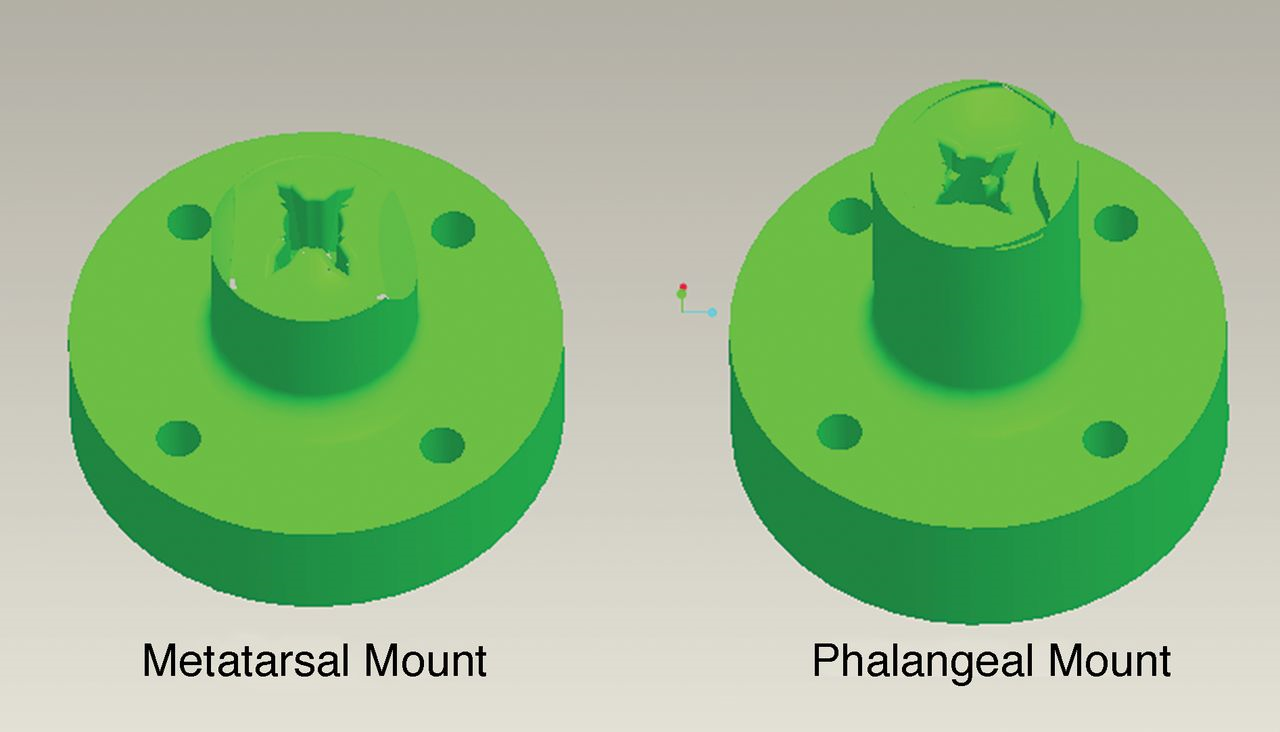
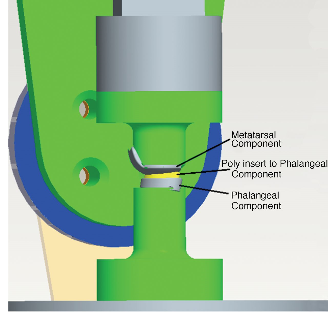
In setting up for a test, the metatarsal and phalangeal components of the implant will be inserted into the respective mounts (Fig. 5). The phalangeal component will be mounted at 25° to the vertical axis. This represents the angle that the long axis of the metatarsal typically makes with the plantar plane of the foot. Then, the center of rotation of the metatarsal component of the implant will be lined up with the center of rotation of the articulating arm in the articulating station (Fig. 4). This will allow the metatarsal component of the implant to rest on the surface of the phalanx component (Fig. 6) when the hydraulic pistons are actuated. Note that equipment are available, such as a coordinate measuring machine or a three-dimensional tracking system, that the user of the simulator may use to determine the center of rotation of the metatarsal component. If necessary, the metatarsal component mount can be shimmed or shaved to insure proper alignment of its center of rotation with that of the articulating arm.
Figure 2.
Solid model of the assembled joint simulator.
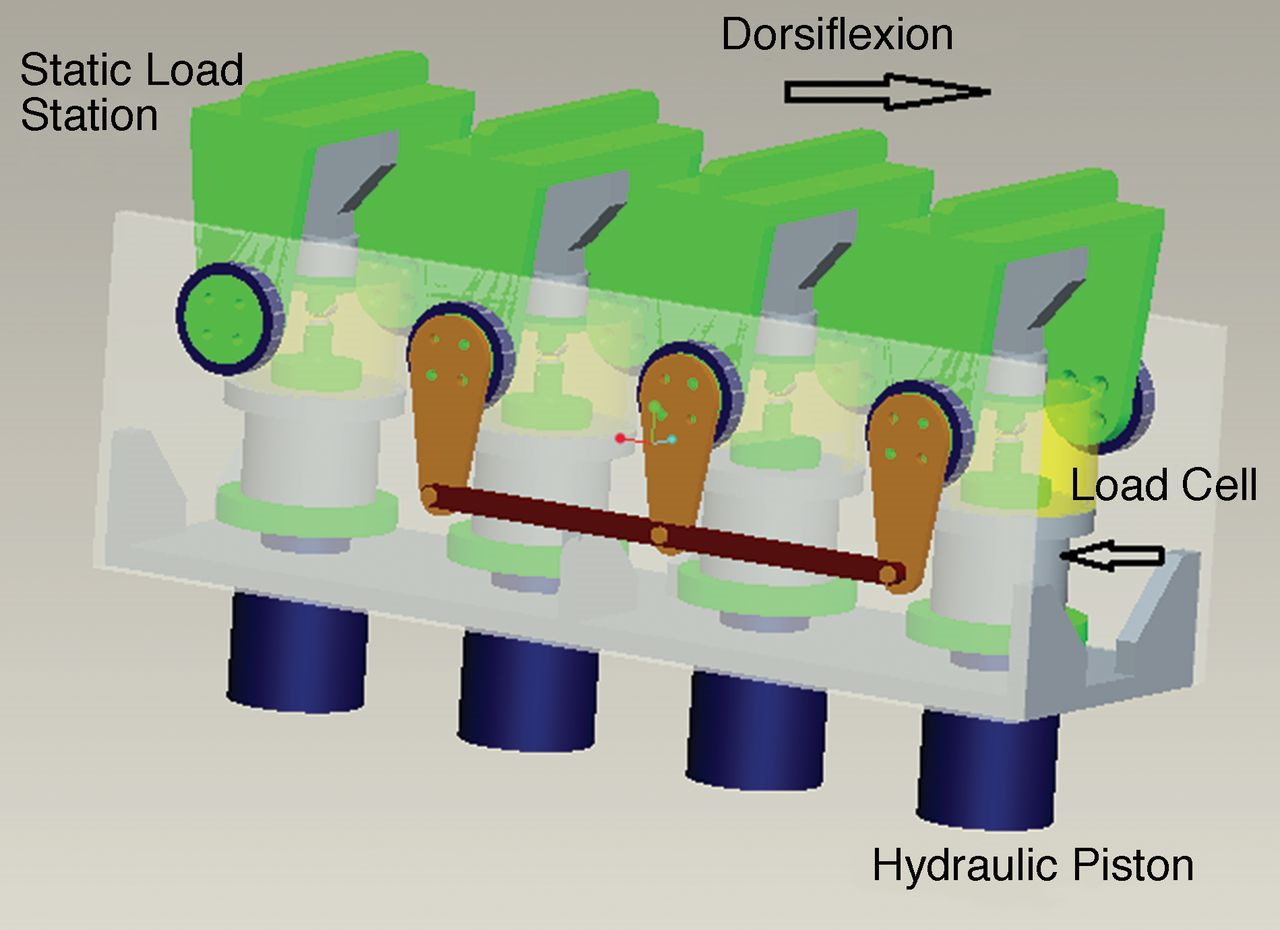
Figure 3.
Solid model of the assembled joint simulator, fully articulated.
The component mounts will be fabricated using a rapid prototyping method, such as stereolithography. For each implant to be tested, a solid model will be created using a commercially available software package, after which a cavity would be created in the mount and then the height of the mount will be adjusted to ensure that the centers of rotation of the implant and the articulating arm are coincident. Each component of the implant will be positioned in its mount in the same way as is done during total first MPJ arthroplasty (Fig. 6); that is, either cemented in a bed of acrylic bone cement or press fitted.
Figure 4.
Solid model of cut-away view of one of the articulating stations.
The control of the simulator will be provided by a commercially available software package, such as FlexTest (MTS; Eden Prairie, MN), Pro-Motion (PMD; Boxborough, MA), or Visual Basic (Microsoft; Redmond, WA). This package will be used to program the controllers to provide the desired articulation and frequency of articulation, read the feedback from the load cells to control the load created by the hydraulic pump that feeds the pistons, and record the number of cycles of articulation.
Figure 5.
Solid models of the implant mounts.
Stress Analysis of an Articulating Test Station
A commercially available finite element analysis (FEA) package (ANSYS 11.0; ANSYS Inc., Canonsburg, PA) was used to perform the stress analysis of an articulating test station, at 0° articulation as well as at 40° articulation, to represent the full range of motion that would be experienced by an implant during a wear test. The converged finite element (FE) meshes of the station, at each of these articulations, obtained using tetrahedral elements (34,448 elements and 104,781 nodes), are shown in Figure 7. Note the high density of the mesh of the fixture on each of the mounts; this was done in recognition of the fact that these components are deemed to be the weakest components in the simulator. For 6061-T6 Al alloy, modulus of elasticity and Poisson’s ratio were taken to be 69 GPa and 0.30, respectively.[23]
Figure 6.
Solid model of close-up view of an implant mounted in the simulator.
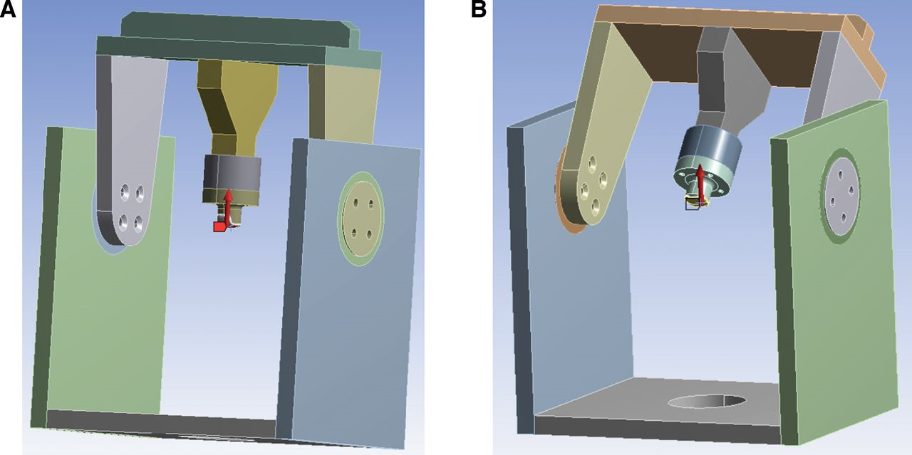
For the analysis, a quasi-static axial load of 1200 N was applied to the surface of the implant (Fig. 8). This force magnitude is twice what would be used during a test. There are two reasons for this approach. First, it would allow investigation of the load capacity of the simulator. Second, it would allow evaluation of the implant under load conditions the joint experiences in activities other than normal gait. Note that, in Figure 8, the FE mesh display was turned off to highlight the direction of the applied load.
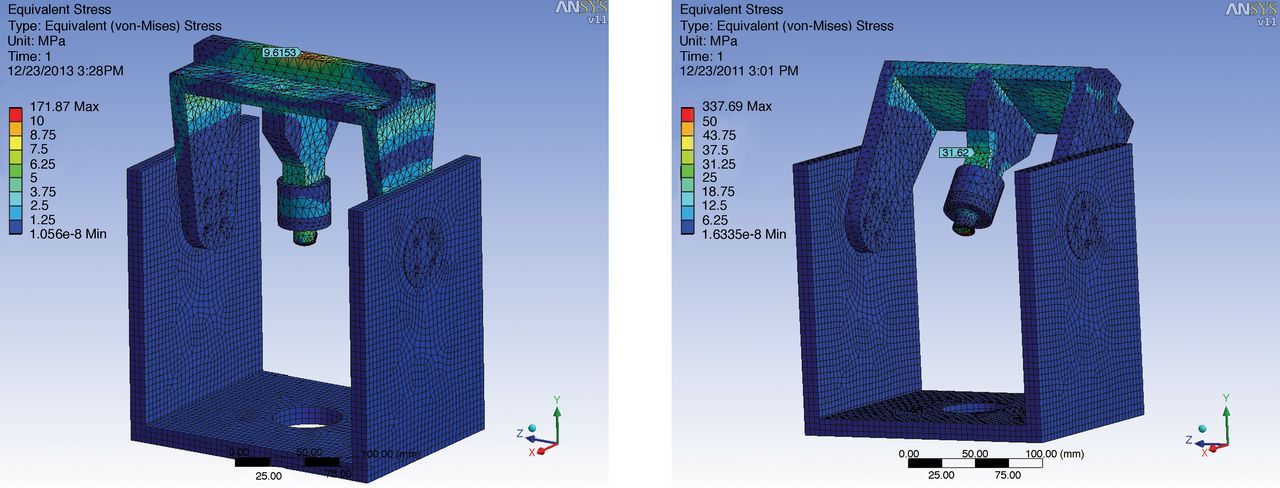
In response to the applied load, there will be stresses at any point in each part of an articulating station, acting in different directions. An equation can be used to combine these stresses into a single stress, called the von Mises stress. The factor of safety of a part against elastic failure may be computed as the ratio of the yield strength of its material of fabrication to the von Mises stress. In the present work, two key features of the von Mises stress contours of an articulating station, obtained at 0° and 40° articulations (Fig. 9), are noted. First, the highest von Mises stress is at the implant-mount fixture interface, a finding that might help explain why implant loosening is such a prevalent failure mode for total first MPJ implants.[14–17] Second, the von Mises stress experienced in the other parts of the station ranges from near 0 to 31.2 MPa, which means that the minimum factor of safety, against elastic failure, is approximately 9 (yield strength of 6061-T6 Al alloy = 276 MPa[23]).
Table 1.
Components List for the Joint Simulator
Future Work
The next stage will be fabrication of a prototype of the simulator. This prototype should then be used to validate our design by comparing results for a given implant, obtained using it, to those obtained from examination of explanted or retrieved implants. Specifically, these results should comprise wear rate (expressed in, for example, mg per 1 million loading cycles), characteristics of the surface of the implant (such as damage and roughness), and characteristics of the wear particles (such as morphology, size distribution, and aspect ratio).
Figure 7.
Converged finite element mesh of the model of the articulating station, at 0° articulation (a) and 40° articulation (b).
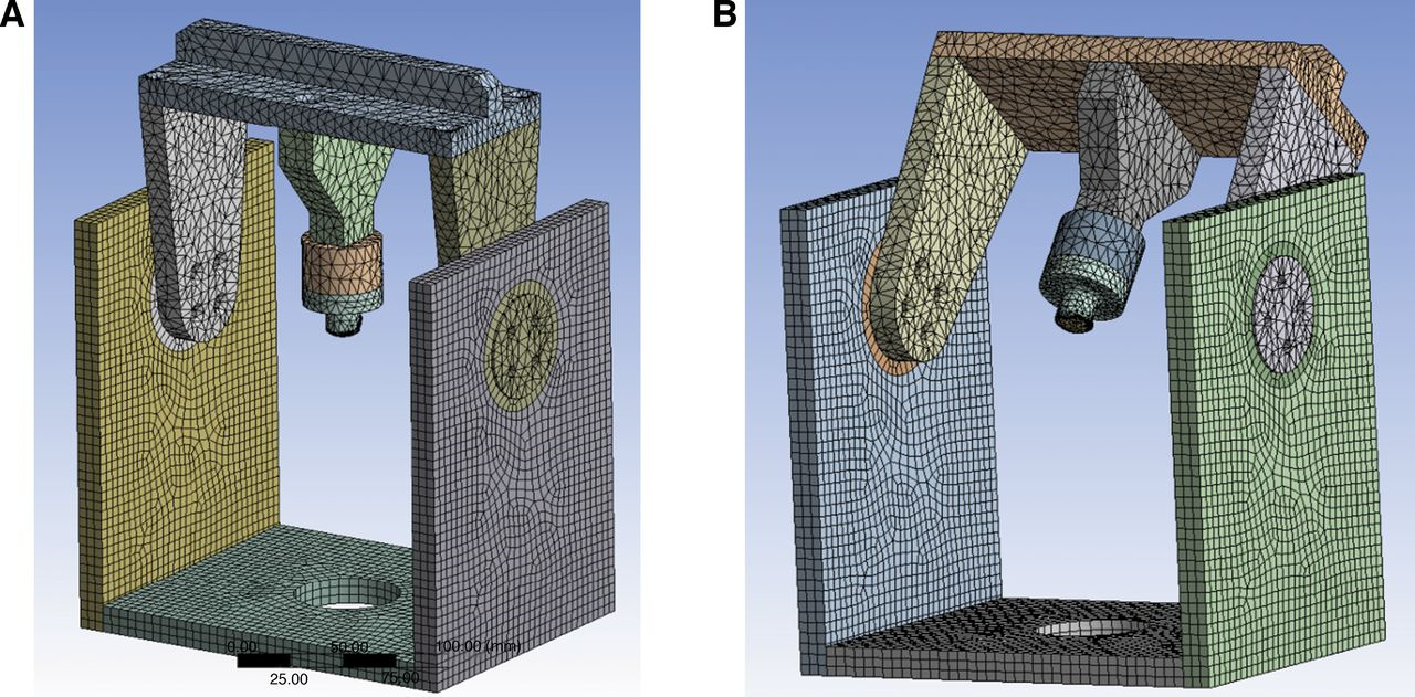
Figure 8.
Quasi-static load of 1200 N applied to a finite element mesh of an articulating station, at 0° articulation (b) and 40° articulation (b). To highlight the load application point, the finite element meshes were turned off.
Conclusions
We designed a multistation first MPJ simulator that may be used to determine the wear rate of a total first MPJ implant. The simulator comprises one static station (to house the control implant during a wear test) and three articulating stations (each of which will house replicates of the implant under test). During a wear test, the implant will be 1) housed in a chamber that contains an aqueous biosimulating solution, at 37 ± 1° C; and 2) articulated at least 40° dorsiflexion, under a 600 N loading, at a frequency of 1 Hz. Furthermore, the designed simulator is flexible enough that it may be used to carry out wear tests on any design of this type of implant.
Figure 9.
The von Mises stress contours for an articulating station.
Stress analysis of a model of an articulating station of the simulator, under a quasi-static load of 1200 N, revealed that the highest stress occurs at the implant-fixture interface. Results on the other parts of the station indicate a minimum factor of safety of approximately 9.
Financial Disclosures
None reported.
Conflicts of Interest
None reported.
References
- Muehleman, C, DBareither, KHuch, et al: Prevalence of degenerative morphological changes in the joints of the lower extremity. Osteoarthritis Cartilage 5: 23, 1997.
- CracchioloIII, A, JBWeltmerJr, GLian, et al: Arthroplasty of the first metatarsophalangeal joint with a double-stem silicone implant: results in patients who have degenerative joint disease failure of previous operations or rheumatoid arthritis. J Bone Joint Surg 74-A: 552, 1992.
- De Frino, PF, JWBrodsky, FEPollo, et al: First metatarsophalangeal arthrodesis: a clinical, pedabarographic and gait analysis study. Foot Ankle Int 23: 496, 2002.
- Goucher, NR, MJCoughlin: Hallux metatarsophalangeal joint arthrodesis using dome shaped reamers and dorsal plate fixation: a prospective study. Foot Ankle Int 27: 869, 2006.
- Cusumano, T: How to treat osteoarthritis of the first MTPJ. Pod Today 17: 28, 2004.
- Harlan, JT, FDGoldman: Long-term follow-up of Keller arthroplasty with irradiated costo-chondral implants. JAPMA 88: 1, 1998.
- Talarico, LM, GRVito, LGoldstein, et al: Management of hallux limitus with distraction of the first metatarsophalangeal joint. JAPMA 95: 121, 2005.
- Fuhrman, RA, AWagner, JOAnders: First metatarsophalangeal joint replacement: the method of choice for end-stage hallux rigidus?Foot Ankle Clin 8: 711, 2003.
- Sung, W, LWeilJr, LSWeilSr, et al: Total first metatarsophalangeal joint implant arthroplasty; a 30-year retrospective. Clin Podiatr Med Surg 28: 755, 2011.
- Deheer, PA: The case against first metatarsal phalangeal joint implant arthroplasty. Clin Podiatr Med Surg 23: 709, 2006.
- Cook, E, JCook, BRosenblum, et al: Meta-analysis of first metatarsophalangeal joint implant arthroplasty. J Foot Ankle Surg 48: 180, 2009.
- Brewster, M: Does total joint replacement or arthrodesis of the first metatarsophalangeal joint yield better functional results? A systematic review of the literature. J Foot Ankle Surg 49: 546, 2010.
- Kim, PJ, DHatch, LADidomenico, et al: A multicenter review of outcomes for arthrodesis, hemi-metallic joint implant, and resectional arthroplasty in the surgical treatment of end-stage hallux rigidus. J Foot Ankle Surg 51: 50, 2012.
- Joyce, TJ: Examination of failed ex vivo metal-on-metal metatarsophalangeal prosthesis and comparison with theoretically determined lubrication regimes. Wear 263: 1050, 2007.
- Ghalambor, N, DRCho, SRGoldring, et al: Microscopic metallic wear and tissue response in failed titanium hallux metatarsophalangeal implants: two cases. Foot Ankle Int 23: 158, 2002.
- Nixon, MF, GJSTaylor: Early failure of the Moje implant when used to treat hallux rigidus: The need for regular surveillance. Int J Clin Foot Science 18: 1, 2008.
- Gibson, JN, CEThomson: Arthrodesis or total replacement arthroplasty for hallux rigidus: a randomized controlled trial. Foot Ankle Int 26: 680, 2005.
- Nawoczenski, DA, JFBaumhauer, BRUmberger: Relationship between clinical measurements and motion of the first metatarsophalangeal joint during gait. J Bone Joint Surg 81-A: 370, 1999.
- Halstead, J, DETurner, ACRedmond: The relationship between hallux dorsiflexion and ankle joint complex frontal plane kinematics: a preliminary study. Clin Biomech 20: 526, 2005.
- Hetherington, VJ, GWChessman, CSteuben: Forces on the first metatarsophalangeal joint: a pilot study. J Foot Surg 31: 450, 1992.
- Lewis, G, PAlva: Stress analysis of a flexible one-piece first metatarsophalangeal joint implant. JAPMA 83: 29, 1993.
- Nordin, M, VHFrankel: Basic Biomechanics of the Musculoskeletal System, 2nd Ed, p201, Lea & Febiger, Philadelphia, 1989.
- Budinski, KG, MKBudinski: Engineering Materials: Properties and Selection, 9th Ed, p756, Prentice Hall, Upper Saddle River, NJ, 2010.
© 2013 American Podiatric Medical Association