


Abstract
Background: Ligaments and cartilage contact contribute to the mechanical constraints in the knee joints. However, the precise influence of these structural components on joint movement, especially when the joint constraints are computed using inverse dynamics solutions, is not clear. Methods: We present a mechanical characterization of the connections between the infinitesimal twist of the tibia and the femur due to restraining forces in the specific tissue components that are engaged and responsible for such motion. These components include the anterior cruciate, posterior cruciate, medial collateral, and lateral collateral ligaments and cartilage contact surfaces in the medial and lateral compartments. Their influence on the bony rotation about the instantaneous screw axis is governed by restraining forces along the constraints explored using the principle of reciprocity. Results: Published kinetic and kinematic joint data (American Society of Mechanical Engineers Grand Challenge Competition to Predict In Vivo Knee Loads) are applied to define knee joint function for verification using an available instrumented knee data set. We found that the line of the ground reaction force (GRF) vector is very close to the axis of the knee joint. It aligns the knee joint with the GRF such that the reaction torques are eliminated. The reaction to the GRF will then be carried by the structural components of the knee instead. Conclusions: The use of this reciprocal system introduces a new dimension of foot loading to the knee axis alignment. This insight shows that locating knee functional axes is equivalent to the static alignment measurement. This method can be used for the optimal design of braces and orthoses for conservative treatment of knee osteoarthritis.
The basic mechanical function of knee joint structures includes guiding the relative motion and the transmission of load between the tibia and the femur. Mechanical instability caused by ligament injuries is believed to be a primary initiating factor for the onset and progression of cartilage degeneration in osteoarthritis.[1,2] However, the quantitative relationship between knee motion and the constraining actions of ligaments and articular surfaces is not yet fully described. Recently, knee joint motion was characterized as being guided by the isometric fascicles in the engaged anterior cruciate, posterior cruciate, and medial collateral ligaments as well as by articular surface contact in the medial and lateral compartments.[3] These anatomical contributors were represented as five mechanical constraints in a 1-degree-of-freedom, parallel-spatial mechanism.
Knee joint motion is currently described in various ways, including a joint coordinate system. This system is based on local anatomical reference frames and partitions general joint motion into the six familiar anatomical motions, or degrees of freedom, of the knee: three translations (proximal-distal, anteroposterior, and mediolateral) and three rotations (internal-external, varus-valgus, and flexion-extension). The knee has also been studied, in a contrasting approach, as a mechanical linkage by relating the instantaneous screw axis ($isa) to ligament alignment including normal contact forces.[4,5] In this manner, the isometric fascicles in the anterior cruciate, posterior cruciate, and medial collateral ligaments and the surface contacts in the medial and lateral compartments are represented by connections composed of standard kinematic pairs linking the femur to the tibia[3,5] or a “parallel spatial mechanism with five constraints.”
It has long been known that the $isa is fundamental to the description of relative joint motion: any infinitesimal motion in the joint may be reduced to a twist ($), a rotation and parallel-translation vector, about the said $isa.[6] Because there is no relative velocity at this $isa, the net sum of intersegmental forces corresponds to no mechanical work, and the function of muscles can be entirely represented by joint movements.
Knowledge of the location, orientation, and any change in position of the $isa in the knee may be the key to the analysis of muscle function during inverse dynamics.[7] This approach is essential to the development of useful kinematic models describing the functional lever arms that may be applied to the accuracy of the joint torques.[8] Of particular clinical relevance, however, is the assumption that when the anterior cruciate ligament is torn, the mechanical system will break down and the $isa will be disrupted, resulting in joint instability.[9] These altered forces cause functional disability and increase the risk or severity of early degenerative arthritis.[10]
Initial treatment for osteoarthritis of the knee, such as prescription of laterally wedged insoles or special valgisation braces designed to reduce the load of the medial compartment, is conservative.[11,12] However, proprioception and stability are only hypothesized, but unproved, underlying explanatory factors and underscore the need for a systematic method to assess the effectiveness (ie, symptom reduction and improvement of knee function and quality of mobility) of braces and orthoses to treat osteoarthritis of the knee. The gold standard to assess knee alignment is via a full-limb radiograph because malalignment increases the risk of progression of knee osteoarthritis.[13] That method is costly, technically difficult (requiring specialized equipment), and causes unwanted pelvic radiation. Furthermore, malalignment provides only a static impression, in only one position in the frontal plane, of the uniplanar forces exerted on the joint. A more complete view of the knee, via three-dimensional dynamic analyses, would better allow for the identification and prioritization of work on the biomechanical factors that are prevalent in the progression of osteoarthritis.
Inverse dynamics has been used as a fundamental computational approach to analyze and estimate joint force and torques. It should be noted that estimation of joint constraints can be classified as an inverse problem, ie, local perturbation being the known or prescribed variable and the equations describing the process being the unknown.[14–16] Alternatively, the external environment could be the unknown.[17] With anthropometric and kinematic information as the input, an inverse dynamics solution produces the force and torque reactions at the various joints.[18] Knowing the coordinates, velocities, and acceleration, the equation for system motion can be solved as a set of algebraic equations (instead of differential equations) to determine the joint reaction forces and driving constraint forces that are required to generate the prescribed motion.[19] Despite their widespread use, it is widely recognized that inverse dynamics solutions are prone to errors.
Uncertainties in inverse dynamics solutions during gait[18] and stance[20] have been reported previously. Segmental anthropometry and the accelerations (based on numerical differentiation of noisy displacement data) are notorious for their inaccuracy; however, they do not make major contributions to the joint torque measurements. This leaves the lever arms, which are very sensitive to marker placement on the skin surface[18] and the inverse dynamics model chosen to estimate joint axes. The measurement errors are partially attributable to the confrontation of two heterogeneous captors, the force plate and the motion capture device, making the two captor frames especially difficult to perfectly coincide in experimental settings.[20,21] Two steps of optimization have been applied to fix the latter problems[22]: an inverse kinematic was optimized for joint angles to be more compatible to the measured marker coordinates, and a residual reaction algorithm was applied to more consistently match joint angles with the measured ground reaction forces (GRFs).
Recent advances in musculoskeletal modeling and computation have enabled investigators to generate gait simulations to estimate muscle forces and joint contact forces.[23,24] Global optimization (also referred to as inverse kinematics) is a common method used in biomechanical data analysis. This method is based on the search of the optimal pose of a multilink model for each data frame such that the overall differences between the measured marker locations and the model’s virtual marker locations (subject to joint constraints) are minimized in a least square sense throughout all of the body segments.[22,25] Moreover, owing to the dynamic inconsistencies between the measured GRFs (and moments) and the model kinematics, a residual reduction algorithm is often applied[22] to make the model joint angles and translations more dynamically consistent. Similarly, accurately locating knee functional axes could be extremely beneficial in correcting knee osteotomy or arthroplasty, hence improving the fidelity of the malalignment measure because the objective of obtaining a whole-leg anteroposterior radiograph in a standing position is assumed to have the alignment of the knee functional axes. The present study can significantly improve the input data (namely, the knee joint center location) for the prediction of constraint forces applied to the medial and lateral compartments.
Consequently, joint biomechanics was presented as one of the key topics for the 2010 American Society of Mechanical Engineers Grand Challenge Competition to Predict In Vivo Knee Loads.[26] The knee functional axes information was referred to as the $isa. In this case, the intersegmental forces, such as ligaments and contact forces, are functionally meaningful if they are defined at an “$isa” that is reciprocally connected,[27] providing an alternative modeling framework that has not yet been explained fully.
Therefore, the first aim of this article is to fully describe the instantaneous motion and restraining forces using Plücker coordinates. Plücker coordinates for screws are preferred in most current works; the basis is composed of three rotations along the coordinate axes and three translations parallel to the axes.[6] The second aim is to explain how constraint forces acting on the joints and infinitesimal displacements are interlinked in terms of the reciprocal conditions. Lastly, we sought to verify this approach by comparing results obtained from an actual instrumented knee. The example illustrated herein and its architecture are easily understood and implemented. The use of a reciprocal system opens a new dimension in connecting foot loading to knee axis alignment. This provides a better understanding of inverse dynamics to assess the effectiveness of braces and orthoses to treat osteoarthritis of the knee. Although the focus is not on exploring computational efficiency, some initial results in that direction were obtained. This was accomplished by comparing performance with rigorous inverse dynamics for knee joint contact forces.
Methods
Reciprocal Screw System
In the present knee model, we assume that the $isa is uniquely determined by its surrounding engaged structures, including the anterior cruciate, posterior cruciate, medial collateral, and lateral collateral ligaments; surface contacts; and external loadings at one instant in time, such that the degree of the entire constrained system should not exceed 5. The reciprocal model has two important roles: first, it predicts the intensities of constraint forces through the anterior cruciate, posterior cruciate, medial collateral, and lateral collateral ligaments and the medial/lateral articular contacts; second, it predicts the position and orientation of the $isa from a reciprocal relationship.
Any system of forces and force couples that acts on a joint structure is reducible to a single wrench ($′), a force and parallel force couple vector, which also lies about a unique screw. For example, in the application of twist and wrench vectors to knee joint mechanics, a 1-degree-of-freedom descriptor of tibial motion about a single twist, $, is established by six in-parallel connections ($′1–$′6) or vectors, all of which are systematically arranged such that they have a common transversal (in reality, this will never happen because of the slackening of some ligaments), with each line imposing one constraint on the tibia (Fig. 1). This is achieved if the $isa in the joint is removed and the tibia is constrained by fitting the six inextensible vectors of the engaged ligaments (tensile) and surface contacts (compressive) to it, the axes of which all intersect along $, resulting in 1 degree of freedom. At that instant, $ represents the $isa of tibial motion relative to the femur. The instantaneous replacement-connection is herein termed a “reciprocal” condition.
Figure 1.
A reciprocal connection scenario compatible with a single degree of freedom of the right knee joint about a single twist ($). The vectors associated with the five constraints $i′ intersect the axis of $. The five intersections are indicated by the circled Xs. For simplicity, the lateral collateral ligament (LCL), as indicated by $6′, is not included in this model. ACL indicates anterior cruciate ligament; MCL, medial collateral ligament; PCL, posterior cruciate ligament; P1 and P2, medial and lateral compartments. (Reprinted with permission from Kim and Kohles.[27])
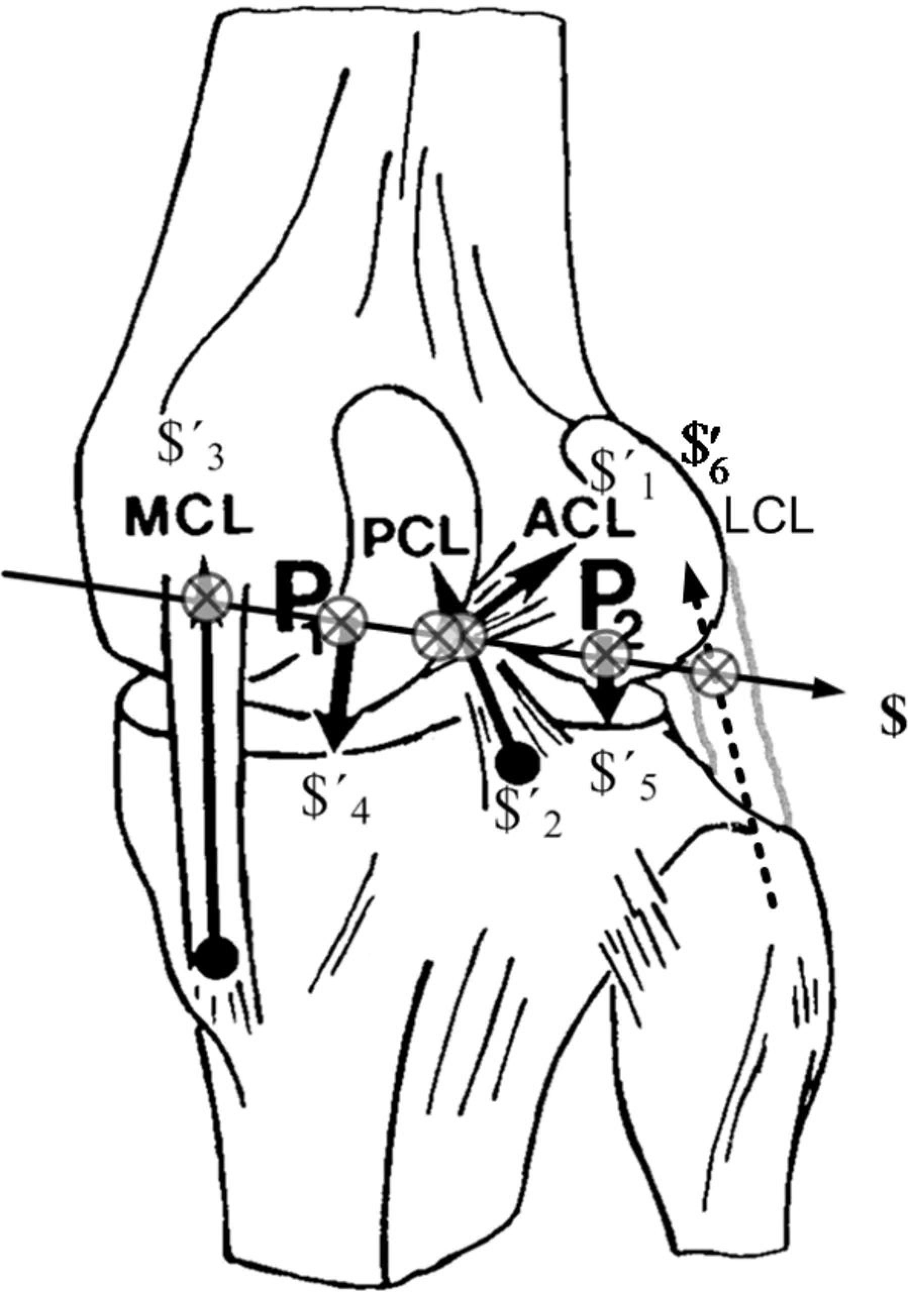
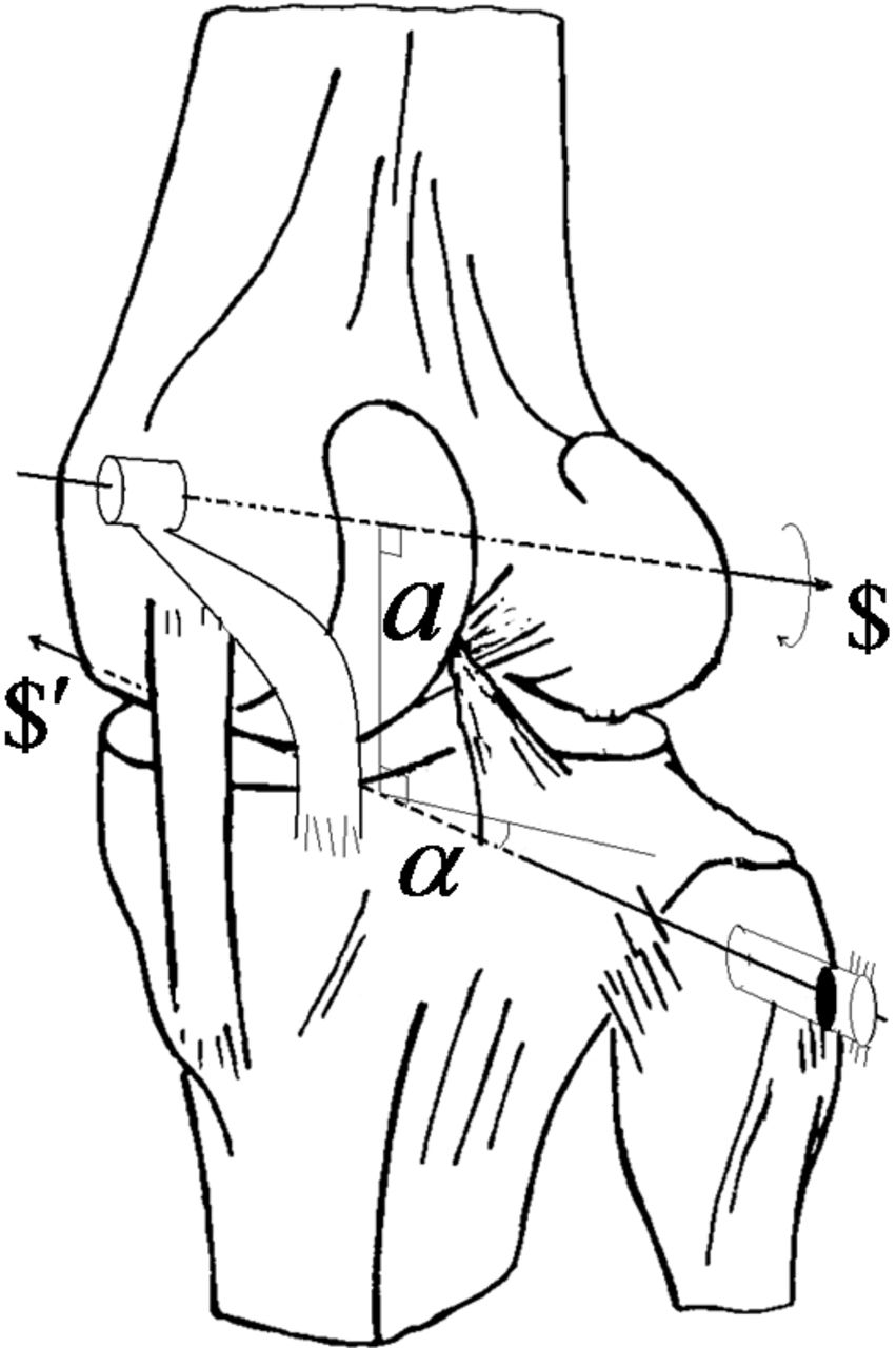
The present model was constructed according to the following assumptions established by previous investigators applying the $isa model[4,28]: 1) the mutual moments of the cruciate ligaments (owing to the minimal moment arm relative to the $isa) and the contribution of tibiofemoral compressive forces on the resultant extensional torque were ignored; 2) ligament fibers are considered compliant structures, whereas the constraint in contact normals are considered rigid when the constraint forces are evoked; reciprocity was observed wherever any axes of constraints intersected along the $isa (Fig. 1) and defined when the rate of work was zero; 3) in steady-state walking (we assume the desired input/output relationship between the shank and thigh was established), the contribution of the subjects’ weights and accelerations are quite small so that joint constraints can be estimated as a first approximation (rather than the rigorous inverse dynamics approach) by simply decomposing the measured GRFs to the corresponding constraints and muscle forces[8,29]; and 4) there is no optimization for the state of indeterminacy; to circumvent the indeterminate problem, all muscle crossing the knee joint is reduced to a single resultant vector. This simplification typically leads to the discovery of new physical and mathematical insights about effectiveness after interventions that otherwise would be difficult to discern. The physical implication of two screws is shown in Figure 2, where t$ and w$′, whose pitch is ht and hw, respectively. The capability of w$′ (the wrench of the intensity w) to changing t$ (the twist of the amplitude t),δ, becomes

Figure 2.
Schematic representing a ground reaction force applied to a right tibia through the wrench ($′) to generate a mutual moment with respect to the twist ($). The common perpendicular between $ and $′ is indicated as line a, and the angle is noted as α.
Knee Constraint Forces Estimation and Generation of $isa
If the normalized screw coordinates of any of six constraints as well as screws on which the wrench of muscle co-contraction is applied are known, then the maximum six screws of the expression can be written as column vectors in a 6 × 6 tensor:
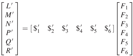
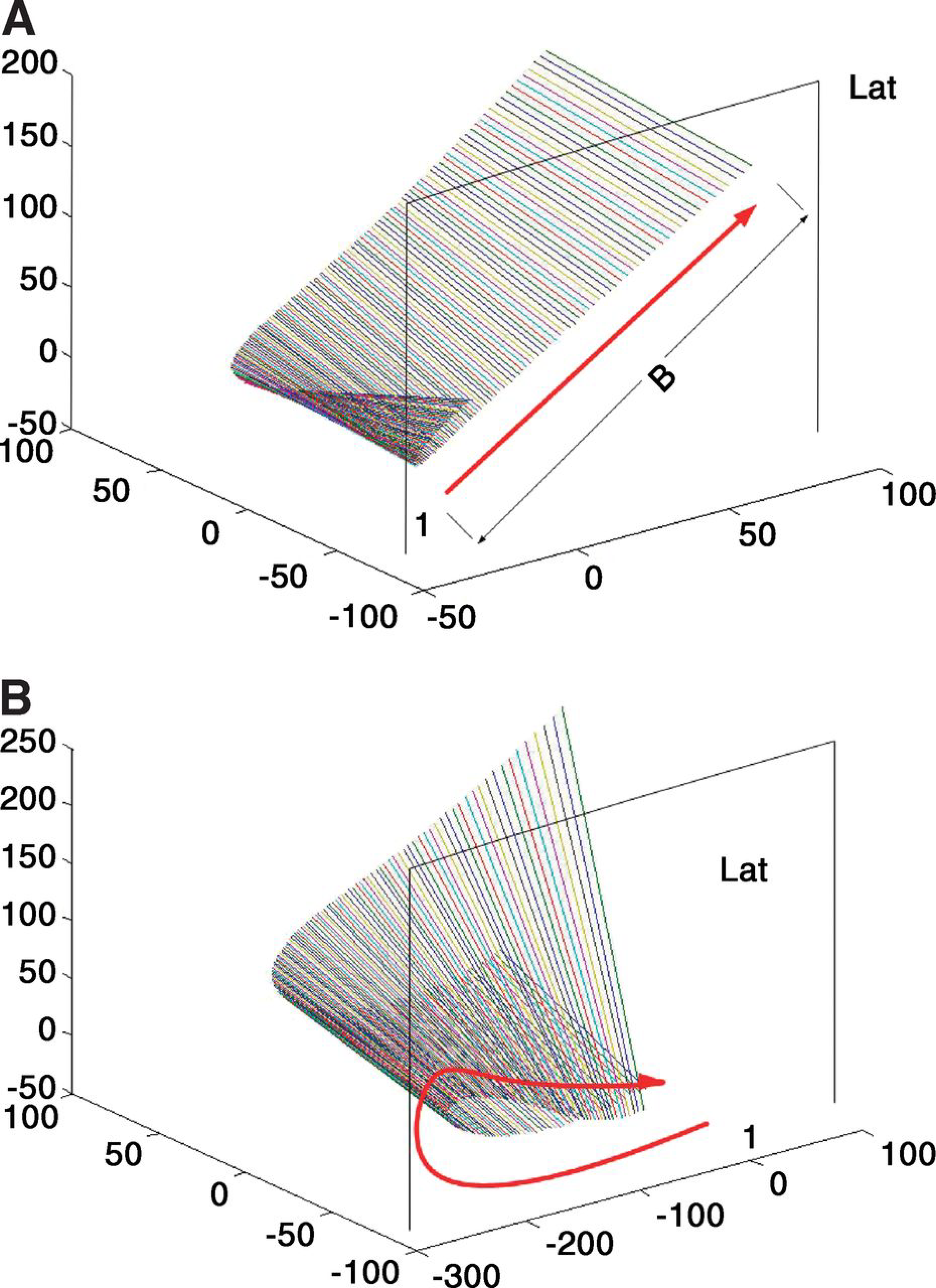
The method that determines the screw axes of the segment in terms of screw coordinates from the rigid body transformation (from noisy data)[30] was applied here, but with real numbers and the 6 × 6 screw transformation matrix in equation 2. We then located the global position of the knee functional axis in terms of the $isa as follows: first, to obtain the Plücker coordinates of the generators for the $isa of the shank and thigh, a set of $isa at consecutive time increments of 0.05 sec, were produced based on a marker system during the stance phase. The time increment was considered as corresponding to two infinitesimally separated positions of the maker set. Second, the $isas can trace out a ruled surface as the segment displaces a set of screws, $1 for the shank and $2 for the thigh (Fig. 3). Then they were reverted back to the $isa of the knee based on the instantaneous twist relationship between three rigid bodies in motion (one is a reference body). Conjugate motion transmission (without disengagement) between two generally disposed axes is possible only if

Figure 3.
Three-dimensional views of the instantaneous screw axis ($isa) from the posteromedial side of the shank (A) and the posteromedial side of the thigh (B). The end points of the axes are at the intersections with medial and lateral (Lat) sagittal planes, located −60 to 60 mm off the origin of the global frame. The first axis, indicated by 1, represents the first step of the $isa. The arrow indicates the direction that each subsequent axis migrates every subsequent 0.05-sec increment. All of the units are millimeters.
To validate the modeling approach, a comprehensive data set was accessed to determine the $isa during gait. This data set included motion capture, ground reaction, electromyography, tibial contact force, and strength data.[26] These experimental gait data were collected from an adult male patient implanted with an instrumented total knee replacement (mass, 68 kg; height, 1.7 m; right knee) and analyzed. The gait trial involved a mediolateral trunk sway gait pattern similar to that previously reported.[32]
Results
We present a comparison of results applying our predictions of contact forces to published data from two different external loading scenarios: scenario A is an estimation of axis-tibiofemoral joint force during normal steady-state waking,[33] and scenario B is instrumented load cell measurements on an implanted adult male patient[34] during a trunk sway gait trial.[26]
For load scenario A, the comparison represents the knee joint loading pattern during steady-state walking rather than on the intensities of contact forces. Overall, the pattern in the results of the combined mediolateral compartment reaction forces obtained in terms of the aligning $isa to the GRF measurements (Fig. 4) is comparable with that obtained during rigorous inverse dynamics (Fig. 4 in the study by Sasaki and Neptune[33]). In the present model, only four static forces were included in the equilibrium equation as medial, lateral, GRF, and a single resultant muscle force without any optimization techniques regarding muscle redundancies.[35]
Figure 4.
To verify positioning of the knee instantaneous screw axis ($isa) in time sequence of motion data, the knee $isa screws are shown to regularly intersect the ground reaction force (GRF) as indicated in the zoomed inset. This representative analysis indicates a reciprocal connection (spatial-temporal representation of knee motion versus the foot loading) between the motion at the knee joint axis and the GRF along with the center of pressure vector. Use of the reciprocal screw opens a new dimension in biomechanical applications on orthopedics in terms of new prescription plans (braces and orthoses). A reaction torque is zero on the knee joint if the GRF line of action intersects the joint axis, or the configuration can exert a large force on the ground without overloading the knee joint. The mechanical advantage is very favorable. A considerable GRF can be exerted on a foot when the vector nearly coincides with a reciprocal screw of joints. The physical implication, especially in terms of the proximity of the interaction of two screws, is presented by comparison with the previous observation.[8,29]
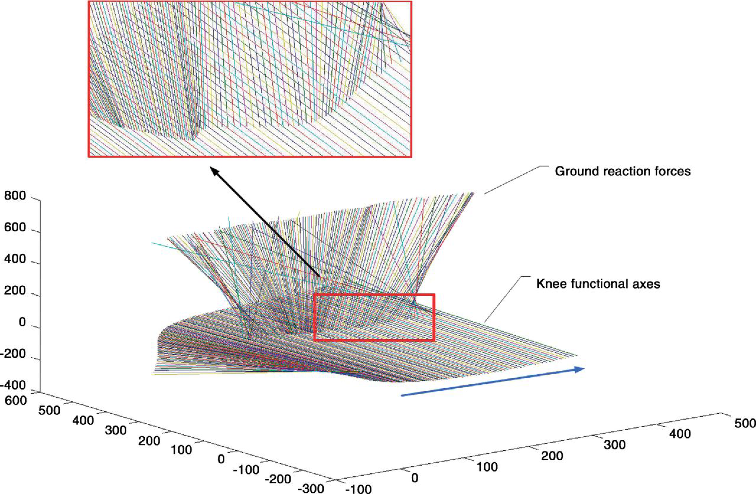
In scenario B, a comprehensive data set was used to determine the mechanical reciprocity in the knee that included motion capture, ground reaction, electromyography, tibial contact force, and strength data.[26] These experimental gait data were collected from the described adult male patient implanted with an instrumented knee replacement and analyzed using our described reciprocal screw system. Coordinates acquired from shank and thigh markers were used to generate screws and were synchronized to the GRFs, with associated center of pressure data obtained during two gait trials that involved a mediolateral trunk sway gait pattern similar to that previously reported.[32] When a limb moves through a succession of distinct phases 1, 2, ... accordingly there is a successive screw $1, $2, ... for each displacement. When the displacement becomes extremely small, the successive screw, ie, $s, approaches $isas so that they are infinitesimally separated from one another and generates a one-parameter series of straight lines, ie, a ruled surface. Each generated line of the ruled surface is conceived to be the residence of a screw, the typical pattern of which was presented in the initiation of the stance phase with small motion increments (0.23°–0.46°) of the shank and thigh in the transverse plane (Fig. 3). The motion pathways of the shank show a distinctive profile characterized by the wider/straight region of resident axes, stretched straight over 100 mm (Fig. 3A), whereas the $isas of the thigh resided in a curved ruled surface (Fig. 3B). Both of the $isas were represented relative to the global frame. Conjugate motion transmission between these screw axes remains only if the line of forces is reciprocal to the instantaneous twist, $isa. Otherwise, the desired input/output relationship is not obtained. This is the theorem with a distinctly different point of view to that of the robotic control paradigm. The $isas of the knee (Fig. 4) were determined by the linear combination of two $isas of the shank and thigh (Equation 3), ie, defined as the input axis and the output axis.
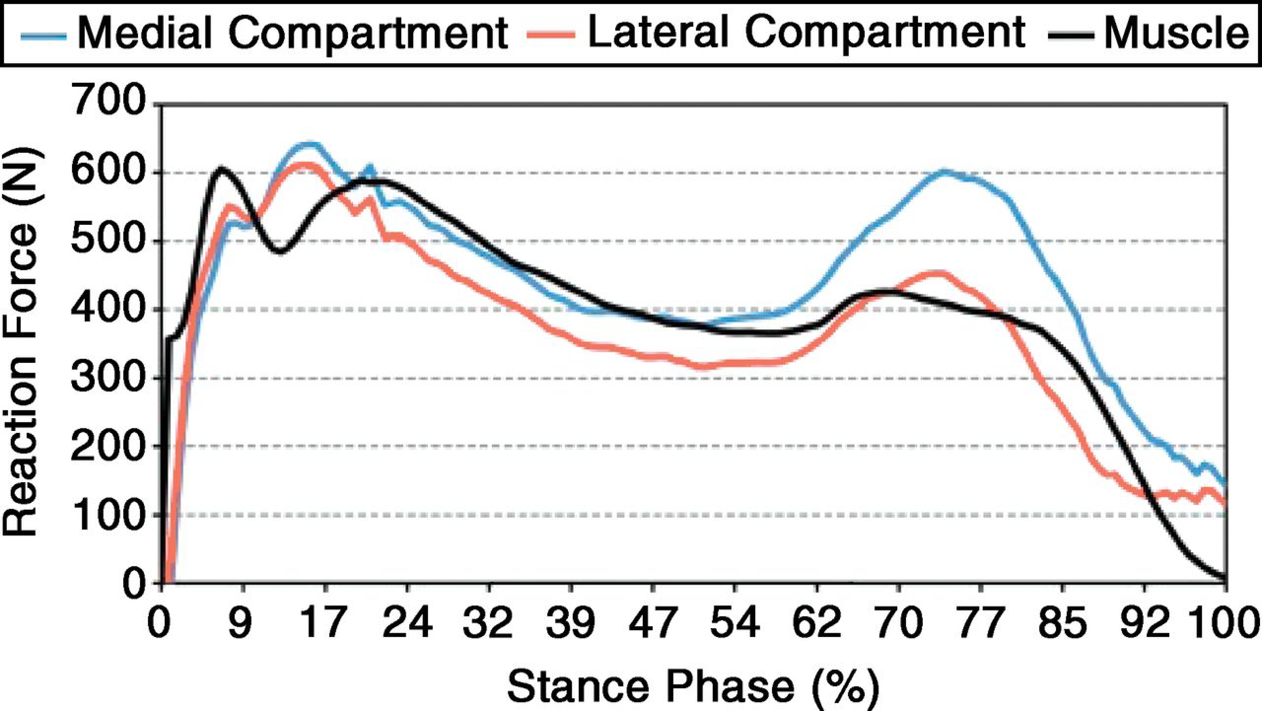
Moreover, by virtue of positioning the $isa of the knee in the global frame (Fig. 4), those $isas could be somewhat connected with the GRF on the wrench screws functionally located at the associated centers of pressure during gait trials.[36] The center of pressure is the point on the ground through which a single resultant force appears to act. The physical implications, especially in terms of closeness to the interaction of two screws, were presented by comparison with the previous observation.[8,29] The instrumented knee data for the trunk sway gait trials for the data sets used in the 2010 Grand Challenge Competition held at the American Society of Mechanical Engineers Summer Bioengineering Conference was compared with the model prediction (Fig. 5). In the model presented in this article, the contribution of the weights and accelerations are not included such that smaller forces were estimated. The forces in the medial and lateral compartments and single muscle forces are presented (Fig. 6) as a first approximation (Equation 3).
Figure 5.
We compared the present results with the instrumented knee data for the trunk sway gait trials for the data sets used in the 2010 Grand Challenge Competition held at the American Society of Mechanical Engineers Summer Bioengineering Conference. The force in the medial compartment was compared. As a limitation, this model used a single muscle. Also note that the magnitude is consistently lower than the measurement entry due to the lack of inertial effects in the lower limb. A similar trend is evident in both approaches.
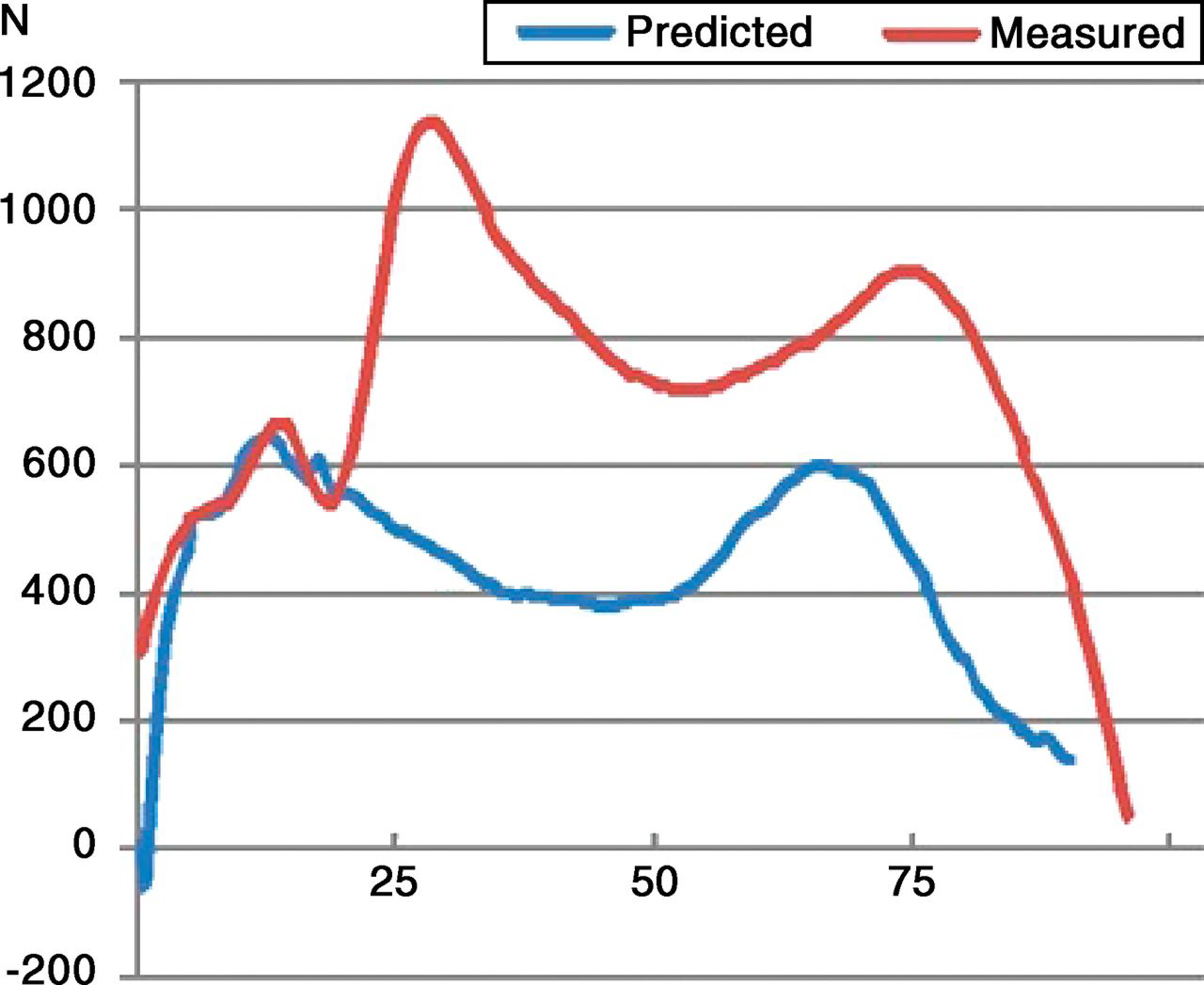
Figure 6.
The model produces the individual reaction force contributions associated with the ground reaction force.
Discussion
The knee joint loading pattern during the stance phase indicates two major peak force levels, the first peak occurring in the early stance (ie, initial heel strike) phase and the second peak occurring in the late stance (ie, propulsion) phase (Fig. 5).
This pattern was consistent with those in previous studies.[33,34] Despite a complex control system, human gait is characterized by smooth, regular, and repeated movements. Such coordinated motion occurs as a direct result of the cyclic activation of many involved leg muscles. It is the innate tension in these muscles that serves as the direct cause of the kinematic patterns that we observe and recognize as locomotion.[8] Walking or locomotion can be modeled as “the translation of the center of gravity along a pathway requiring the least expenditure of energy,” thereby minimizing energy consumption.[29] (p515) Note that the line of GRF action relative to the knee joint center is very close to itself (Fig. 4). The line of GRF action relative to the joint center was considered to be a determining factor for flexion or extension.[8,29,37] This phenomenon was also observed as the flat ruled surface whose components, generated by knee $isas, actually interact very closely with the GRF (Fig. 4). A closer view revealed that indications of neither forward nor backward formations of $isa versus GRF exist. Arriving at the reciprocity condition requires that the twist and the wrench, two distinct elements, be projective, ie, one-to-one correspondence in terms of their unique relationship as theorized in the “Knee Constraint Forces Estimation and Generation of $isa” section. The spatial interval defined as the adjacent screw axes plays the role of the time interval between two consecutive time actions. This establishes a means to “propagate” the forces across a joint at the interface between two adjacent limb segments systematically. If the foot is held still, braking torques on the knee joint are required to balance a GRF acting on the foot. From the reciprocal condition, we know that the reaction torque on the knee joint is zero if the GRF is along the reciprocal screw. Therefore, during the stance phase, one can align the GRF with the axis of the reciprocal screw and eliminate the reaction (braking) torque about the knee joint. The reaction torque of the GRF will instead be taken by the base of the knee structure, and the torque actuated by muscles can be used solely for a firm grip on the floor without a loss. This special configuration is herein defined as a “stationary configuration of the knee.” The goal of initial treatment for osteoarthritis of the knee is to transfer pathologic load bearing to the normal compartment of the knee. During the transfer of compartment forces by orthoses, it is important to redistribute the forces evenly over two compartments while maintaining this stationary configuration. In much of robotics research, designers emphasize the need to avoid this special configuration whenever the robot is being controlled along a smooth and continuous path. However, in biology, the stationary configuration during the stance phase can be used to an advantage. A simple toggle mechanism is an example of a device that is used to provide a large mechanical advantage when the knee joint is aligned with the GRF. Any stance phase of the leg at or close to a stationary configuration can exert a GRF of substantial intensity without overloading any of the muscles surrounding the knee joint. The mechanical advantage in that case is very favorable. Small changes in walking kinematics that can have a significant effect on the magnitude of the knee joint forces have been reported. These previous attempts could not establish any close relationship between static alignment measures and gait patterns (eg, joint constraint forces) in patients with osteoarthritic knees.[38,39] However, the osteoarthritic patients appeared to walk with stiff and tight knees (a reduction in flexion/extension). This abnormality can be explained in that the joint axis of a pathologic knee is not accurately aligned reciprocally to the line of GRF action. Therefore, the reaction torque caused by the foot/ground at the knee will be taken on partially by muscles surrounding the joint, and the muscles cannot entirely work by flexion/extension during stance (ie, perform a braking torque). In simpler terms, it is not an efficient locomotive mode if one is applying the brakes all the time during normal motion. Thus, altering walking mechanics and muscle coordination patterns through interventions directly influences the reciprocity conditions, which results in altering joint forces. The change in joint forces by altering interventions could be predicted as a simple approximation (Fig. 6) for clinicians rather than as a rigorous inverse dynamics approach. Clinicians may be more interested in an intrasubject variability that can be produced from intervention than in intersubject variability.
The whole-leg anteroposterior radiograph is currently considered the gold standard for determining axial alignment and serves as the basis for planning treatment in patients with osteoarthritis. These findings suggest that the static alignment measures associated with the stationary configuration of the knee could better explain the malalignment measure. New trials should investigate the long-term benefits of braces and orthoses using the new approach proposed in this study. We need to establish a new paradigm for braces and orthoses intended to reduce load that promises a beneficial effect. Is the aspect of unloading essential, or are stability and proprioception the most important factors? The latter question can be answered by exploring the stationary configuration of the knee.
Acknowledgment
Professor B.J. Fregly at the University of Florida for making the data publicly available. The first author also thanks his mother, Soonhee Won, for her continuous encouragement of this research.
Financial Disclosure
Experimental data were provided for validation through the Grand Challenge Competition to Predict In Vivo Knee Loads, a component of the Symbiosis Project funded by the National Institutes of Health via the NIH Roadmap for Medical Research (grant U54 GM072970).
Conflicts of Interest
None reported.
References
- Setton, LA, ElliottDM, MowVC: Altered mechanics of cartilage with osteoarthritis: human osteoarthritis and an experimental model of joint degeneration. Osteoarthritis Cartilage7: 2, 1999.
- Hsieh, YF, DraganichLF, HoSH, et al: The effects of removal and reconstruction of the anterior cruciate ligament on the contact characteristics of the patellofemoral joint. Am J Sports Med30: 121, 2002.
- Wilson, DR, FeikesJD, and O’ConnorJJ: Ligaments and articular contact guide passive knee flexion. J Biomech31: 1127, 1998.
- Goodfellow, J and O’ConnorJ: The mechanics of the knee and prosthesis design. J Bone Joint Surg Br60: 358, 1978.
- Menschik, A: Mechanics of the knee-joint: 1 (author’s transl) [in German]. Z Orthop Ihre Grenzgeb112: 481, 1974.
- Ball, R:A Treatise on the Theory of Screws,Cambridge University Press,Cambridge, England, 1998.
- van den Bogert, AJ, ReinschmidtC, and LundbergA: Helical axes of skeletal knee joint motion during running. J Biomech41: 1632, 2008.
- Vaughan, CL: Are joint torques the Holy Grail of human gait analysis?Hum Move Sci15: 423, 1996.
- Montgomery, SC, MooreheadJD, DavidsonJS, et al: A new technique for measuring the rotational axis pathway of a moving knee. The Knee5: 289, 1998.
- Johnson, RJ, BeynnonBD, NicholsCE, et al: The treatment of injuries of the anterior cruciate ligament. J Bone Joint Surg Am74: 140, 1992.
- Rubin, R and MenzHB: Use of laterally wedged custom foot orthoses to reduce pain associated with medial knee osteoarthritis: a preliminary investigation.JAPMA95: 347, 2005.
- Kerrigan, DC, LelasJL, GogginsJ, et al: Effectiveness of a lateral-wedge insole on knee varus torque in patients with knee osteoarthritis. Arch Phys Med Rehabil83: 889, 2002.
- Sharma, L: The role of varus and valgus alignment in knee osteoarthritis. Arthritis Rheum56: 1044, 2007.
- Kim, W, VoloshinAS, and StanleyHJ: Modeling of heel strike transients during running. Hum Move Sci13: 221, 1994.
- Kim, W and VoloshinAS: Role of plantar fascia in the load-bearing capacity of the human foot. J Biomech28: 1025, 1995.
- Kim, W, TanJ, VelosoA, et al: The natural frequency of the foot-surface cushion during the stance phase of running. J Biomech44: 774, 2011.
- Kim, W, TrethewayDC, and KohlesSS: An inverse method for predicting tissue-level mechanics from cellular mechanical input. J Biomech42: 395, 2009.
- Riemer, R, Hsiao-WeckslerET, and ZhangX: Uncertainties in inverse dynamics solutions: a comprehensive analysis and an application to gait. Gait Posture27: 578, 2008.
- Shabana, A:Computational Dynamics,John Wiley & Sons Inc,New York, 2010.
- Guelton, K, DelpratS, and GuerraTM: An alternative to inverse dynamics joint torques estimation in human stance based on a Takagi-Sugeno unknown-inputs observer in the descriptor form. Control Eng Pract16: 1414, 2008.
- McCaw, ST and DeVitaP: Errors in alignment of center of pressure and foot coordinates affect predicted lower extremity torques. J Biomech28: 985, 1995.
- Delp, SL, AndersonFC, ArnoldAS, et al: OpenSim: open-source software to create and analyze dynamic simulations of movement. IEEE Trans Biomed Eng54: 1940, 2007.
- Richards, C and HigginsonJS: Knee contact force in subjects with symmetrical OA grades: differences between OA severities. J Biomech43: 2595, 2010.
- Kim, HJ, FernandezJW, AkbarshahiM, et al: Evaluation of predicted knee-joint muscle forces during gait using an instrumented knee implant. J Orthop Res27: 1326, 2009.
- Lu, TW and O’ConnorJJ: Bone position estimation from skin marker co-ordinates using global optimisation with joint constraints. J Biomech32: 129, 1999.
- Fregly, BJ, BesierTF, LloydDG, et al: Grand challenge competition to predict in vivo knee loads. J Orthop Res30: 503, 2012.
- Kim, W and KohlesSS: A reciprocal connection factor for assessing knee-joint function. Comput Methods Biomech Biomed Engin15: 911, 2012.
- Zheng, N, FleisigGS, EscamillaRF, et al: An analytical model of the knee for estimation of internal forces during exercise. J Biomech31: 963, 1998.
- Vaughan, CL: Theories of bipedal walking: an odyssey. J Biomech36: 513, 2003.
- Kiat Teu, K and KimW: Estimation of the axis of a screw motion from noisy data: a new method based on Plucker lines. J Biomech39: 2857, 2006.
- Dooner, DB: On the three laws of gearing. J Mechanical Design124: 733, 2002.
- Mundermann, A, AsayJL, MundermannL, et al: Implications of increased medio-lateral trunk sway for ambulatory mechanics. J Biomech41: 165, 2008.
- Sasaki, K and NeptuneRR: Individual muscle contributions to the axial knee joint contact force during normal walking. J Biomech43: 2780, 2010.
- Zhao, D, BanksSA, D’LimaDD, et al: In vivo medial and lateral tibial loads during dynamic and high flexion activities. J Orthop Res25: 593, 2007.
- Crowninshield, RD and BrandRA: A physiologically based criterion of muscle force prediction in locomotion. J Biomech14: 793, 1981.
- Fuller, EA: Center of pressure and its theoretical relationship to foot pathology. JAPMA89: 278, 1999.
- Perry, J:Gait Analysis: Normal and Pathologic Function,Slack, Thorofare,NJ, 1992.
- Teixeira, LF and OlneySJ: Relationship between alignment and kinematic and kinetic measures of the knee of osteoarthritic elderly subjects in level walking. Clin Biomech (Bristol, Avon)11: 126, 1996.
- Wang, H and OlneySJ: Relationships between alignment, kinematic and kinetic measures of the knee of normal elderly subjects in level walking. Clin Biomech9: 245, 1994.
© 2013 American Podiatric Medical Association