


Abstract
To meet the future demands of high-rate transmission and full-coverage networks, radio frequency–underwater wireless optical communication (RF-UWOC) relaying systems are considered a promising heterogeneous communication architecture. The rate-splitting (RS) scheme, through its power allocation (PA) mechanism, provides a generalized framework for the performance evaluation of such systems. Based on this, this paper analyzes the performance of an RS-based RF-UWOC system under hardware impairments (HIs) and interference. Analytical expressions of the outage probability (OP) and ergodic capacity (EC) for the considered system are formulated within a generalized framework, which encompasses the conventional RF-UWOC system as a special case. The results indicate that the OP and EC are affected by HIs, interference transmit power, the PA coefficients, channel fading, pointing errors (PEs), and detection types of the UWOC link. Furthermore, the asymptotic results for the OP and the diversity gain (DG) are explicitly characterized. For a fixed interference transmit power, the DG is mainly dominated by the channel fading severity, PEs effect, and the detection scheme. When the interference transmit power is comparable to the desired signal power, the system operates in an interference-limited regime, and the DG decreases to zero. It is also revealed that HIs and PA coefficients affect the coding gain but not the DG. Moreover, the existence of an optimal PA scheme improves the reliability of the RS-based system.
1. Introduction
Space–air–ground–sea-integrated networks (SAGSINs) are widely recognized as a key architecture for next-generation communication systems [1,2]. In this context, underwater operations, marine environmental monitoring, and maritime Internet-of-Things applications impose ever-increasing demands for high-reliability and high-rate communications. With its capability to support high-throughput underwater links, underwater wireless optical communication (UWOC) serves as an essential solution for enhancing underwater communication performance and facilitates the development of mixed radio frequency (RF)–UWOC communication systems [3]. The RF-UWOC system combines the advantages of mature terrestrial infrastructure in RF communication with the large-capacity characteristic of UWOC links. Compared with conventional UWOC systems, which are limited in transmission distance, the RF-UWOC relaying system significantly extends the effective coverage by introducing RF links for access or backhaul, and exhibits high robustness in challenging underwater turbulence environments. This architecture provides a solid networking foundation for SAGSINs and offers reliable communication support for underwater operations and marine observation [3,4]. In previous studies, in-depth discussions were conducted regarding RF-UWOC system performance, and the motivation and significance of this mixed communication system were clearly explained [3,4,5,6,7,8,9,10,11,12,13,14].
1.1. Related Works
With the aid of relaying mechanisms, RF-UWOC systems can substantially extend the transmission distance and support high-rate underwater data transfer via UWOC links. In particular, the studies in [3,4,5,6,7,8] focused on mixed RF-UWOC links applying decode-and-forward (DF) and amplify-and-forward (AF) relaying strategies, where the outage probability (OP), average bit error rate (BER), and ergodic capacity (EC) were reported for reliability evaluation. The secrecy behavior of RF-UWOC relaying systems was further addressed in [9,10], where the secrecy outage probability (SOP) under different fading conditions was derived and analyzed. Moreover, several studies combined satellite links with UWOC links to construct satellite–UWOC relaying systems, in which OP and SOP were comprehensively examined [11,12]. In addition, an RF-UWOC system assisted by an unmanned aerial vehicle (UAV) and based on non-orthogonal multiple access was investigated in [13]. In [14], a reconfigurable intelligent surface (RIS) was incorporated into the RF-UWOC system to enhance its security performance.
Despite the numerous advanced studies on RF-UWOC systems, non-ideal transceiver components in practical deployment scenarios inevitably introduce hardware impairments (HIs), thereby degrading system performance [15]. Moreover, multiple sea-surface nodes share spectrum resources and cause co-channel interference (CCI), which further degrades system performance [16]. In [17,18], the authors analyzed the impact of HIs and interference in other configurations, such as UAV-aided uplink systems. Moreover, in our conference version, an RF-UWOC system impaired by the CCI was investigated [19], where two interference conditions were discussed. However, for RF-UWOC systems, most existing studies assume ideal hardware conditions and ignore the impact of interference, and the performance analysis under the coexistence of both conditions has not been fully studied.
Recently, a rate-splitting (RS) scheme has attracted considerable attention, as it can effectively alleviate the performance degradation caused by HIs or interference and thus enhance the transmission reliability and robustness of the system [20,21]. RS is an advanced physical layer technique that improves wireless network capacity through flexible interference management mechanisms and is considered one of the most promising multiple-access methods in future communication systems. In the RS framework, user information is divided into common and private components and transmitted in a superimposed manner. Upon reception, the common message is decoded first, and its corresponding interference is removed using successive interference cancellation (SIC), followed by the decoding of the private message [22]. By virtue of this decoding mechanism, the RS exhibits strong robustness and adaptability to complex channel environments. Consequently, the RS scheme offers greater design flexibility, such as an adjustable power allocation (PA) mechanism. This advantage is particularly significant in scenarios with HIs, enhanced security requirements, or specific design constraints. At present, the RS has been applied to terahertz (THz) systems, where it effectively improves the outage performance of THz links [23]. Very recently, RS has been introduced into a mixed RF-free space optical (FSO) system [24]. Unlike FSO channels, UWOC links exhibit more challenging physical characteristics inherent to underwater environments. Despite these differences, most prior RS research focuses on multi-user or terrestrial FSO-based relaying scenarios, while the application of RS to RF-UWOC architectures remains unexplored. For such systems, RS introduces a generalized transmission framework, which allows conventional transmission to appear as a special case when the PA coefficient of the common stream equals zero.
1.2. Motivations and Contributions
Inspired by previous discussions, this paper investigates the performance of an RS-based RF-UWOC system under the joint effects of HIs and interference, where the RS scheme is adopted to enhance design flexibility and establish a unified framework for performance analysis. To the authors’ knowledge, the joint impact of HIs and interference on RF-UWOC systems, as well as the application of RS in this context, has not yet been investigated. The key contributions of this work are summarized below.
- An RS-based RF-UWOC DF relaying system with HIs and interference is presented, where the RF link follows Nakagami-m fading, the interference links are modeled as Rayleigh fading, and the UWOC link experiences exponential-generalized gamma (EGG) fading with pointing errors (PEs).
- The OP and EC of the proposed system are analytically derived within a generalized framework. This framework also covers special cases, including the conventional RF-UWOC without RS and the RF-UWOC system without HIs.
- To gain deeper insights, we derive the asymptotic expressions of the OP. Two interference scenarios are examined, and the corresponding diversity gains (DGs) are obtained. In Case I, with fixed interference transmit power, the DG is jointly dominated by the channel fading parameters, the detection scheme adopted in the UOWC link, and the PEs. In Case II, when the interference transmit power is comparable to the desired signal power, the DG is equal to zero and the OP exhibits an error floor.
- In the RS-based RF-UWOC system, the optimal PA coefficient is determined, which minimizes the system OP and improves overall performance.
1.3. Organization and Symbols
The remainder of this paper is structured as below. Section 2 presents the RS-based RF-UWOC DF relaying system, provides details of the signal transmission framework and defines the equivalent signal-to-interference-plus-noise-and-distortion ratio (SINDR). Section 3 introduces the channel statistical models of all links. Based on these fading models, the OP and EC of the system are derived, and several special cases are discussed. The asymptotic behavior under different interference conditions is further analyzed. Furthermore, the optimal PA coefficient is investigated. The numerical results are illustrated and analyzed in Section 4. Section 5 provides the conclusions of this paper. The derivations of the theorems are included in Appendix A, Appendix B and Appendix C. Key parameters and symbols are list in Table 1.
Table 1.
Key parameters and symbols.
2. System Model
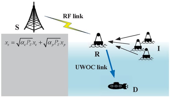
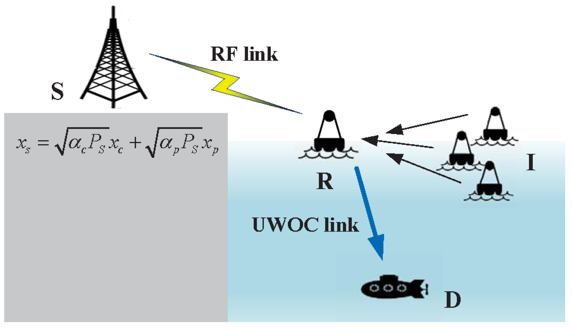
Figure 1 presents the considered RS-based RF-UWOC relaying scenario under the HIs and CCI. A DF relay (R) positioned at the sea surface assists the information delivery between the source (S) and the undersea destination (D). The first hop (S-R) uses the RF transmission, while the second hop (R-D) adopts UWOC transmission. In this model, S first applies the RS scheme to divide the message into a common stream and a private stream. These streams are transmitted to R through the RF link, where the received signal is affected by CCI from K interference nodes (I) with only RF transmission capability. After decoding the received signals, R forwards the common and private streams to D via the UWOC link. Considering the non-ideal characteristics of RF and optical devices in actual systems, all nodes experience HIs. Moreover, each terminal operates with a single antenna, and perfect instantaneous channel state information (CSI) is available for all links.
Figure 1.
System model.
2.1. Signal Transmit
At the first stage, the RS scheme is applied at S. The transmitted message is split into a common component and a private component. The common component is encoded into a common data stream , and the private component is encoded into a private data stream , both satisfying . Accordingly, the transmit signal at S is given by
where denotes the transmit power at S, and and represent the PA coefficients for the common and private streams, respectively, satisfying .
Based on this, the received signal at R is formulated as
where denotes the channel coefficient of the S-R link, stands for the signal satisfying at the kth I, represents the channel gain from kth to R (I-R) link, holds for the transmit power of the kth I, is the additive white Gaussian Noise (AWGN) at R with zero mean and variance , represents the distortion noise resulting from the combined HIs of the S-R and I-R links and is modeled as , with
where and stand for the respective hardware levels of the S-R and I-R links [15]. For simplicity, the HIs from each interference node I to R are assumed to be identical, i.e., .
At the second stage, the common and private streams are decoded at R using the DF protocol. Then, R performs electrical-to-optical conversion and transmits the streams to D through the UWOC channel. The received signal at D can be expressed as
where is the decoded signal, represents the electro-optical conversion factor, characterizes the channel gain of R-D link, which accounts for underwater optical channel fading and PEs, denotes the corresponding distortion noise and is modeled as [15], stands for the signal power emitted by R, is the AWGN at D, and r specifies the detection scheme, where holds for heterodyne detection (HD) and refers to intensity modulation/direct detection (IM/DD), respectively.
2.2. Equivalent SINDR
For the considered DF relaying system, due to the adoption of the RS, both R and D decode the common and private streams separately. As a result, the SINDR expression at each hop contains two parts, namely the common stream part and the private stream part.
Using (2) and the RS strategy, R first decodes the common data stream while treating as interference. After successful decoding of , it is removed using the SIC, and is subsequently decoded. The SINDRs at R for the common and private streams are obtained, respectively, as
where , with .
Following (4), the SINDRs at D for the common and private streams are expressed, respectively, as
where , with denoting the electrical signal-to-noise ratio (SNR). The parameter is obtained from the average SNR , which is defined as [7].
In the present analysis, the DF relaying protocol is adopted, the equivalent SINDRs are characterized as
3. Performance Analysis
The statistical properties of all channels are first presented under ideal HIs conditions, which serves as the foundation for deriving the analytical OP and EC for the proposed RS-based RF-UWOC system with HIs and interference. The asymptotic OPs and the corresponding DG under different interference scenarios are examined. The optimal PA coefficient is also obtained in this section.
3.1. The Channel Models
Since the SINDR expressions in (5)–(8) depend on , , and , the probability density function (PDF) and cumulative distribution function (CDF) of are first given as follows, where . Based on these distributions, the CDFs of the SINDRs are then obtained by applying variable transformations and subsequently used to evaluate the system OP and EC.
3.1.1. The RF Channel
For the S-R link, the channel gain follows Nakagami-m fading. Accordingly, the PDF and CDF of are written as [6]
where m specifies the S-R link fading parameter, and and refer to the Gamma and incomplete Gamma functions, respectively [25].
3.1.2. The Interference Channels
For each kth I-R link, Rayleigh fading is assumed and the channel gains are considered independent and non-identically distributed. Consequently, the PDF and CDF of are expressed as [26]
where , stands for the count of distinct diagonal elements of , specify their multiplicities, and refers to the th characteristic coefficient associated with [26].
3.1.3. The UWOC Channel
For the UWOC channel, EGG fading is assumed. Moreover, we consider the PEs effect. The PDF and CDF expressions of are given as [27,28]
where represents the Meijer’s G function [25], , , a, b, and c denote the EGG distributed parameters for characterizing the UWOC channel fading, and the constants and model the PEs, as described in [29].
3.2. Outage Probability
3.2.1. Exact Results
For the considered RS-based DF relaying system, an outage occurs if either the common or private stream fails to be decoded at R or D. Consequently, the OP corresponds to the probability that the equivalent SINDR of the common stream lies below its threshold , or the equivalent SINDR of the private stream falls below its threshold , expressed mathematically as
Thus, the system requires both components to be successfully decoded, and the system OP is defined as [24]
where and denote the CDF-based OPs of the common and private components, respectively. To obtain , the expressions of and are calculated separately as follows.
Theorem 1.
Proof.
See Appendix A. □
By replacing with in (18), the OP of the common component is obtained. The following observations can be made. When or , the common stream is always in outage, and the OP equals 1. The CDF-based expressions in (18) are valid when the condition of is satisfied.
Likewise, following the derivation in Appendix A, the expression of can be obtained as
where
and
where with , and . Similarly, if or , the private stream remains in outage and the OP equals 1. The expressions in (22) and (23) hold only when .
By combining (17), (18), and (21), the OP of the considered RS-based system is obtained. From this result, it can be observed that the OP is influenced by . When is too small, the common stream may fail to be decoded due to insufficient allocated power. Conversely, when is excessively large, the power assigned to the private stream is significantly reduced, which may also lead to decoding failure. Therefore, only within a suitable range of can both the common and private streams be reliably decoded. The specific impact of the PA coefficient on system performance will be further discussed in Section 3.4.
Special case: For the system without the RS scheme and considering ideal HIs, i.e., and , the expression of reduces to
which is consistent with the result in [19].
3.2.2. Asymptotic Results
To better understand the diversity behavior of the system, asymptotic analysis is provided. With the limit of high SNR, the asymptotic OP is approximated as [24]
where and denote the CDF-based asymptotic OPs of common and private components, respectively. In what follows, we obtain their asymptotic results.
For the common component, by employing (18), is expressed as [7]
where and denote the asymptotic CDFs of the S-R and R-D links for the common component, respectively.
Theorem 2.
For the S-R link, by letting , the asymptotic CDF under different interference conditions is given as follows:
- Case I: If the interference transmit power is comparable to the desired signal power , we have
- Case II: If is fixed as a constant, we obtain
Proof.
See Appendix B. □
For the R-D link, by letting in (20), is given by
where , , , and .
3.2.3. Diversity Gains
Through the above asymptotic analysis, the variation trends of the system performance can be revealed, and the effects of key parameters, such as channel fading, detection schemes, interference, HIs, and PA coefficients, on the system diversity performance can be further analyzed. At high SNR, the asymptotic OP can be expressed as [15], where is the average SNR, and and denote the coding gain (CG) and DG, respectively, characterizing the horizontal shift and slope of the curve.
Consequently, for Case I, when the interference transmit power is fixed, the DG is obtained from the asymptotic results in (26), (28), (29), (30), (31), and (32) as
It follows that, in this case, the interference level, HIs level, and PA coefficients affect the CG rather than the DG. For instance, higher values of , , and reduce , which indicates more severe HIs and consequently increases the OP. In contrast, the channel fading parameters (i.e., m, ), the detection scheme employed in the UWOC link (i.e., r), and the PEs parameter (i.e., ) dominate the DG of the system.
In Case II, if is comparable to the desired signal power, i.e., , the DG is obtained from the asymptotic results in (26), (27), (29), (30), (31), and (32) as , which implies an interference-limited error floor. In this regime, interference becomes the dominant term affecting system performance, while other parameters, such as the HIs, PA coefficients, PEs, channel fading, and detection parameters, affect only the CG.
3.3. Ergodic Capacity
For the RS-based RF-UWOC DF relaying system, two independent streams are decoded sequentially using SIC. Therefore, the overall EC equals the sum of the capacities of the common and private components and is defined as
where
with , and is obtained as [24], where . The presence of HIs complicates the derivation of an analytical framework for the EC of the proposed system, as reported in [15,18]. Therefore, a numerical integration approach is employed to approximate the EC. In the following, expressions for , , , and are provided.
Theorem 3.
By employing the numerical integration approach, the expression of can be derived as
where M denotes the number of Gauss–Laguerre integration points, and represent the weight factor and the zeros of the Laguerre polynomials, respectively, which are provided in Table 25.9 of [31], and is given by
Proof.
See Appendix C. □
Likewise, following a similar approach to Appendix C, the expression of is given by
where
With the help of (36) and (38), the EC for the common component can be obtained.
Similarly, the EC for the private component is computed as
where and , with and derived as
and
3.4. Power Allocation Optimization
In RS-based systems, properly adjusting the PA coefficient can effectively improve the system performance. When is small, the common stream suffers from insufficient transmit power and cannot be reliably decoded, leading to system outage. As increases, the reliability of the common component is enhanced while the private stream still retains sufficient power. In this region, proper PA between the common and private streams reduces the OP, allowing it to reach its minimum value. However, when is further increased, the transmit power allocated to the private stream is significantly reduced, which degrades its decoding performance and results in an increased OP. Therefore, there is an optimal value of to effectively enhance overall transmission performance. From the asymptotic results in (28), (29), (31), and (32), the OP is related to the parameters , , , and . According to (25), the optimization problem is stated as
where and . Since , , , and are all functions of , the objective function can be minimized by setting [23]. Based on this observation, the optimal PA coefficient is calculated as
which can also be expressed as the ratio . This result reveals that the optimal PA coefficient is solely a function of the target threshold and does not depend on the HI parameters.
4. Numerical Results
This section provides numerical demonstrations using the derived analytical expressions, with results verified through Monte Carlo simulations. The number of simulation runs is set to . The BMGF can be numerically computed in MATLAB or MATHEMATICA using a contour integral-based numerical approach ([30] Table II). Three representative parameter sets are adopted to characterize the UWOC channel fading under different bubble levels (BLs) and temperature gradient (TG) conditions, as listed in Table 2 (these UWOC channel parameters are obtained by fitting experimental data from laboratory water-tank measurements and are used to characterize the severity of underwater optical turbulence fading (see [27] for more details)). Unless otherwise specified, the parameters are set as follows: dB, , , (the PE parameters and depend on the optical beam width , the receiver aperture , and the jitter variance . In this work, and are adopted as in [29], yielding . The parameter characterizes the severity of PEs; a larger results in smaller and thus more severe PEs), and the fading parameters of UWOC are , , , , and . The hardware levels are assumed to be identical for all links, i.e., . Moreover, the average SNRs of the S-R and R-D links are assumed to be equal, i.e., .
Table 2.
UWOC channel fading parameters for different BL and TG.
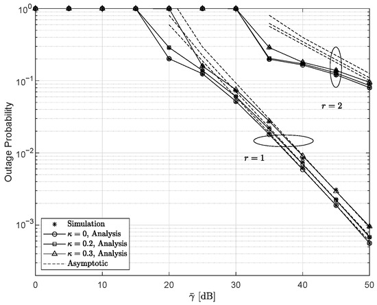
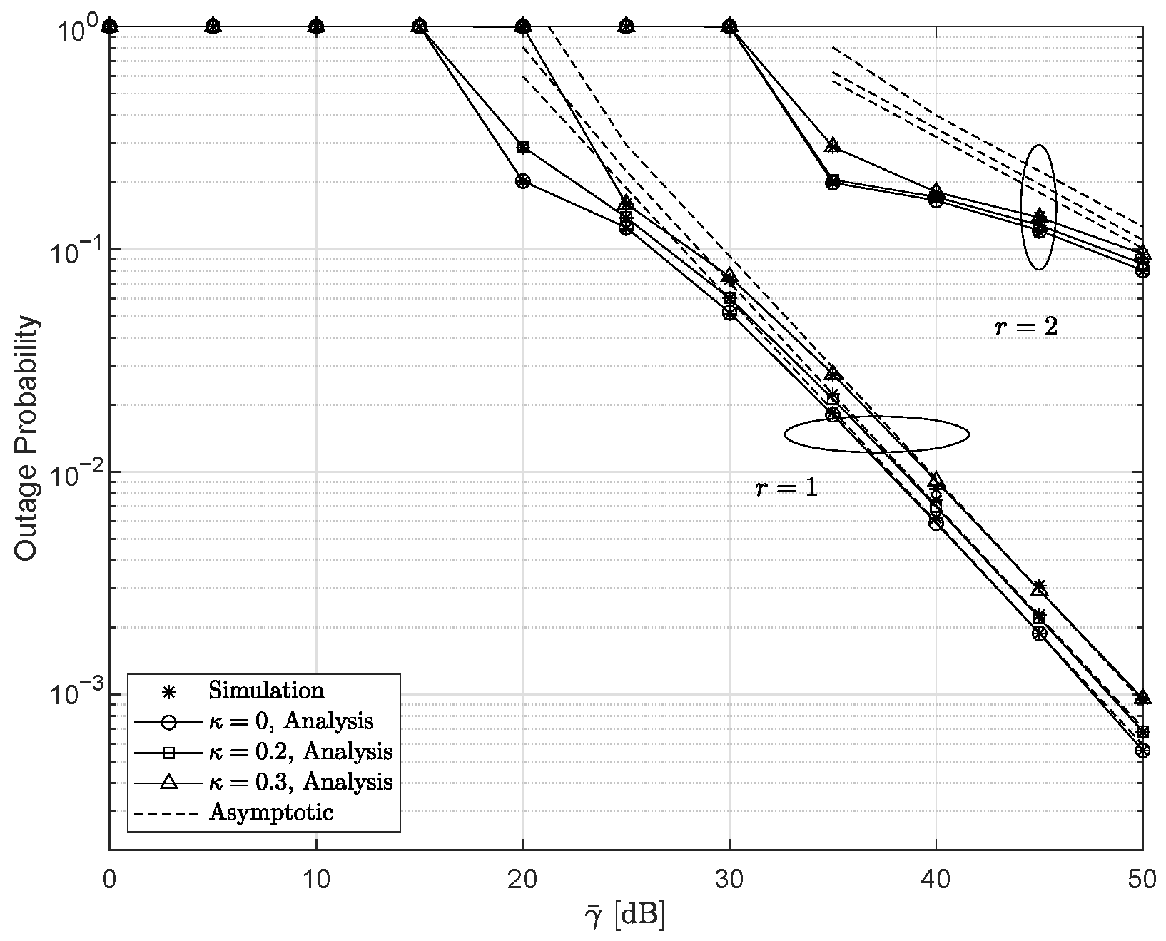
Figure 2 illustrates the OP and its asymptotic behavior as functions of for different values of and r, with , , and dB. As expected, it is observed that the IM/DD yields an inferior performance compared with the HD. As the hardware level decreases, the OP degrades accordingly, while ideal hardware consistently outperforms the non-ideal case. Moreover, the results reveal that the detection type governs the slope of the OP curves, namely the DG, whereas the level of HIs primarily affects the CG without altering the DG.
Figure 2.
Outage probability versus for various and r settings, with , , and dB.
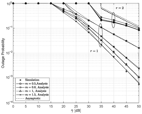
Considering different channel fading conditions and detection schemes, Figure 3 depicts the OP and its asymptotic results versus with , , , and dB. The validity of the derived DG in (33) is confirmed by the asymptotic analysis. For the HD scheme (), when the fading parameter m takes relatively small values (e.g., or ), the DG is governed by m. As the value of m increases to 1 or 1.5, the DG becomes dependent on . In contrast, under the IM/DD scheme, the DG remains unchanged as the value of m increases from 0.5 to 1.5. This observation implies that, at high SNRs, system performance is primarily constrained by channel fading characteristics and the detection scheme employed in the UWOC link.
Figure 3.
Outage probability versus for several r and m values, with , , , and dB.
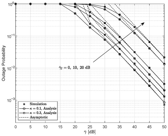
Figure 4 shows the effects of interference and HIs on the OP with , , and . As expected, the outage performance degrades as increases. Moreover, when the hardware level increases from to , the OP becomes higher, indicating more severe performance loss. For this parameter setting, the DG is given by and remains unaffected by either the interference transmit power or the HI level.
Figure 4.
Outage probability as a function of for various and configurations for , , and .
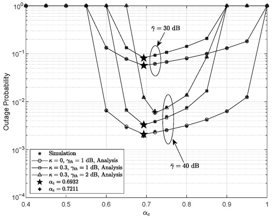
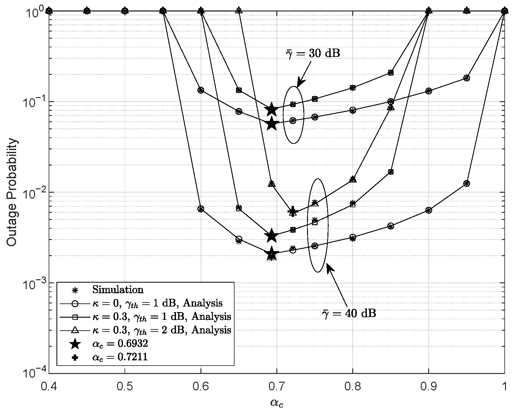
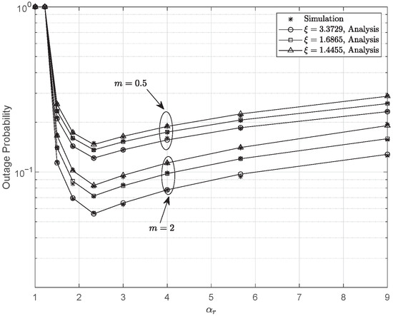
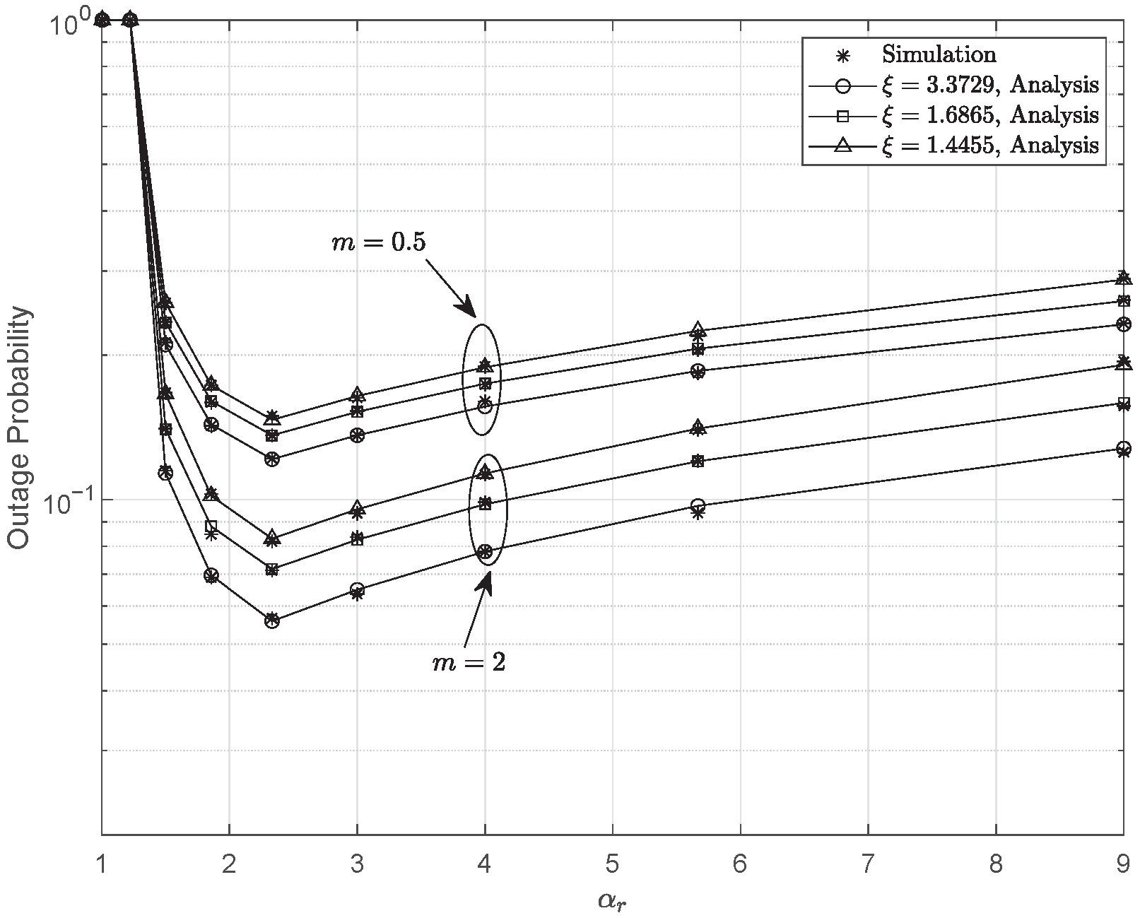
Figure 5 depicts the OP versus for different values of , , and , with , , , and dB. One can observe that the OP decreases as increases. Compared to the ideal hardware case, the presence of HIs leads to noticeable performance degradation. More importantly, the OP first decreases and then increases as grows, which reveals a clear U-shaped behavior and indicates the existence of an optimal . When takes a small value, the power assigned to the common component is inadequate. As a result, the maximum achievable SINDR at the receiver does not reach the required threshold, i.e., . In this case, the common stream cannot be decoded successfully, leading to system outage. As increases, the condition is satisfied and successful decoding of the common component becomes possible. Meanwhile, the power allocated to the private stream remains sufficient, such that . However, when exceeds a certain threshold, the value of reduces to a level that no longer supports private stream decoding, i.e., , which again results in system outage. Therefore, in the RS-based RF-UWOC system, the OP is affected by the variation in the PA coefficients. As shown in Figure 5, the optimal equals 0.6932 for dB and 0.7211 for dB, which is consistent with the expression derived in (44). In general, in practical system design, the value of is typically set to be slightly larger than to first ensure the successful decoding of the common stream, and then guarantee reliable decoding of the private stream.
Figure 5.
Outage probability as a function of for several , , and values, with , , , and dB.
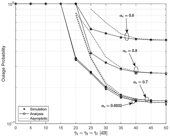
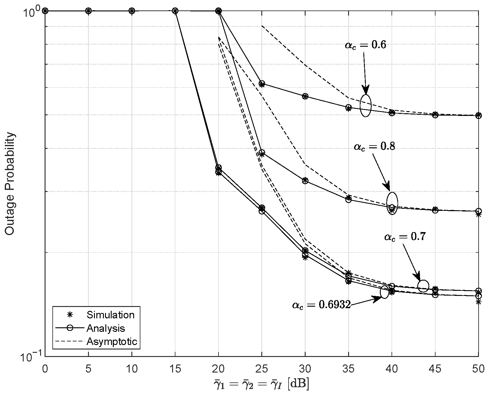
In the scenario where the interference transmit power approaches the desired signal power , Figure 6 show the plot for OP for different values of . The parameters are set as and . According to the previous analysis, the optimal PA coefficient is for dB. As expected, the optimal outage performance occurs at , yielding up to 69% and 47% improvements in system reliability compared with the cases of and , respectively. Additionally, when both the interference and signal powers are in the high-SNR regime, the system becomes interference-limited. As a result, the OP exhibits an error floor and the DG reduces to zero. Therefore, interference management or appropriate power control is required in practical deployments.
Figure 6.
The variation in the outage probability versus for different values of , with dB, , and .
Defining , the OP versus for various m and settings is plotted in Figure 7. The parameters are configured as dB, dB, , and . It is observed that the outage performance deteriorates when is either too small or too large. This also suggests that the PA coefficients should be carefully selected in practical system design. An appropriate can balance the decoding reliability of the common and private streams, thereby reducing the OP. The optimal value of is observed to be equal to , as predicted by (44). With larger m, the quality of the S-R channel improves, which benefits the overall system performance. Similarly, a higher mitigates the severity of PEs, producing a better outage performance.
Figure 7.
Outage probability versus for various values of and m, when dB, dB, , and .
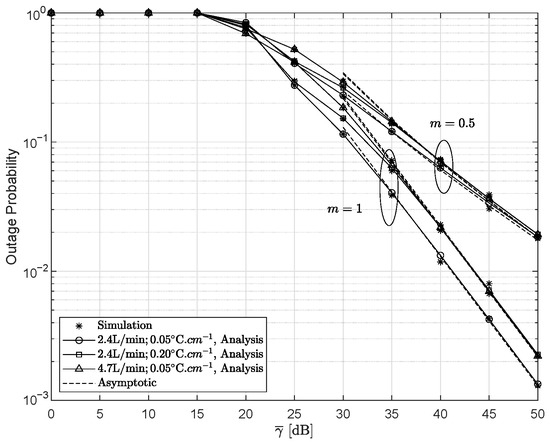
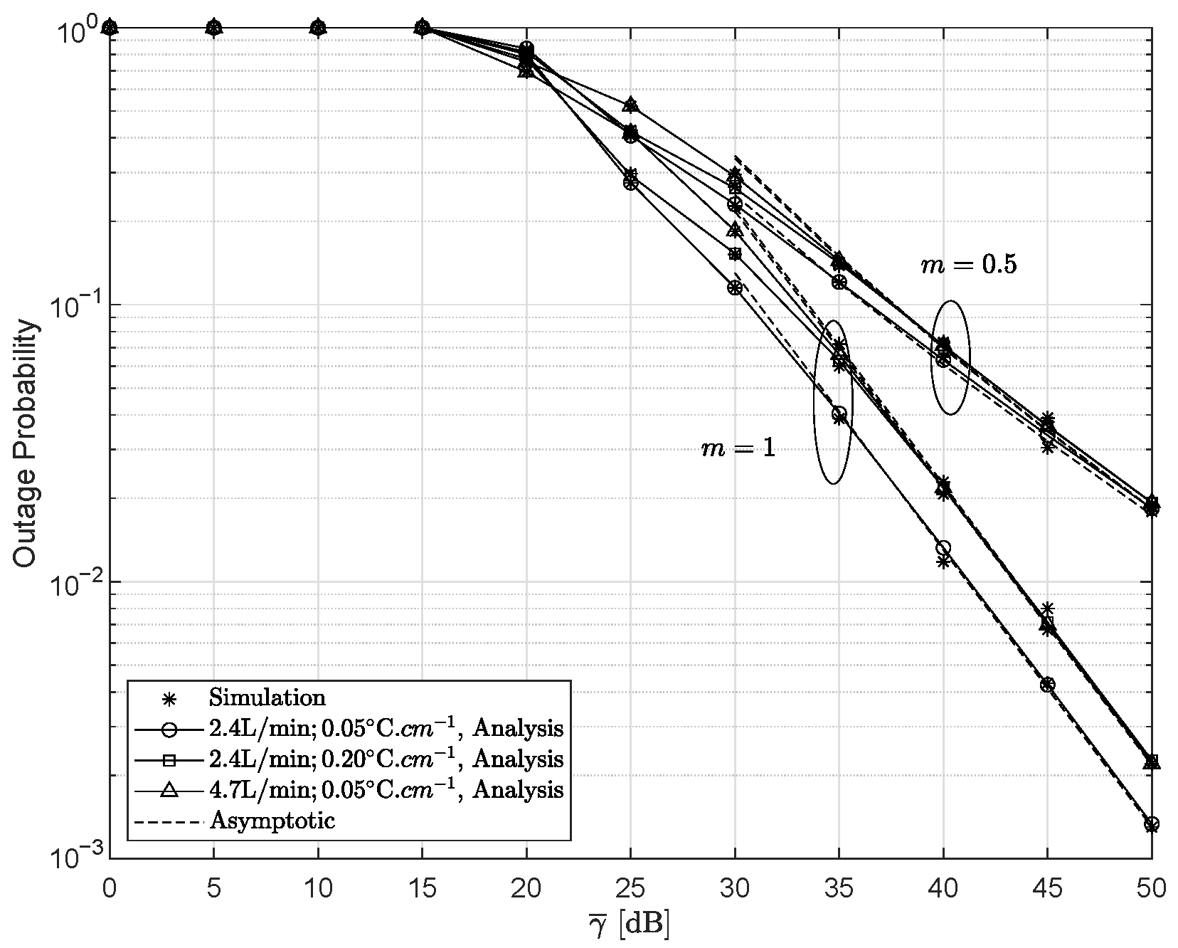
Figure 8 presents the OP and its asymptotic results as functions of for several fading settings of the RF and UWOC, with dB, , , and . The UWOC fading parameters are set according to Table 2. Under strong fading conditions, the OP increases by approximately 69% at dB, which indicates a degradation in system reliability. It is observed that these parameters only affect the CG of the system. In the high-SNR regions, the outage performance remains dominated by the parameter m.
Figure 8.
Outage probability as a function of under different fading conditions, when dB, , , and .
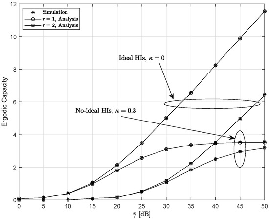
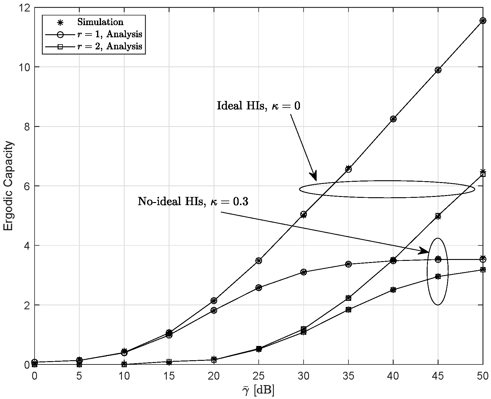
Figure 9 presents the EC for the ideal HIs system and the non-ideal HIs system for dB, , and . One can notice that the EC of the ideal HIs system increases with the SNR, whereas the EC of the non-ideal HIs system exhibits an error floor at the high SNRs. This behavior arises because HIs limit the achievable performance of the system. In addition, the EC obtained with the HD scheme exceeds that of the IM/DD scheme.
Figure 9.
The variation in the ergodic capacity under different HIs conditions for different detection schemes when dB, , and .
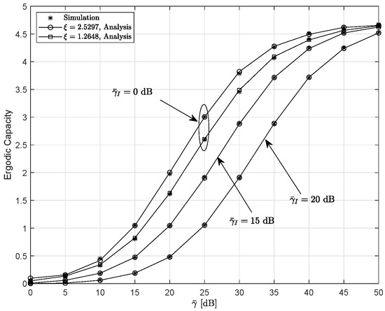
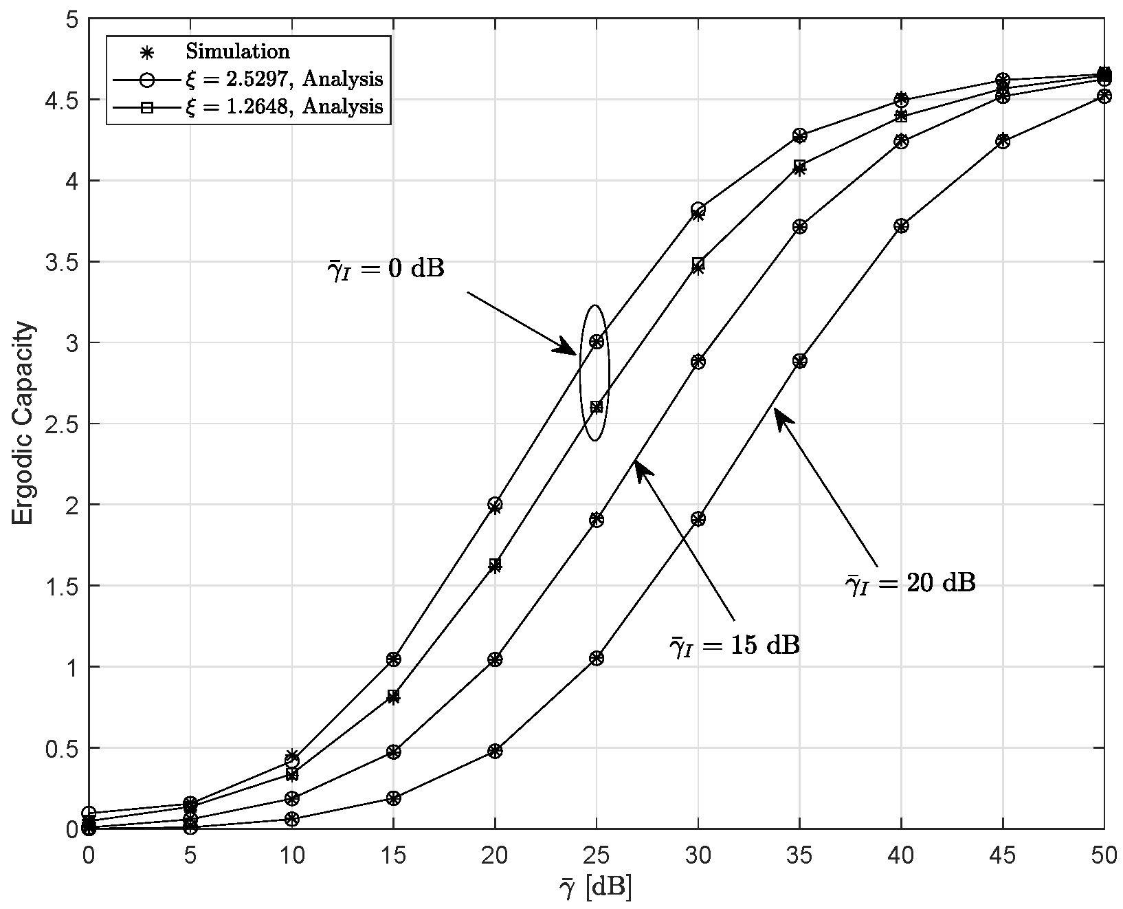
Figure 10 plots the EC versus for different parameters of and . The other parameters are set as , , and . The EC shows an increasing trend with respect to . In contrast, an increase in the interference transmit power degrades the EC.
Figure 10.
Ergodic capacity versus for the different value of and when , , and .
5. Conclusions
This paper investigated an RS-based RF-UWOC DF relaying system in the presence of HIs and CCI. The OP and EC were derived and analyzed under different PA coefficients, interference and hardware levels, fading parameters, detection schemes, and PEs. Moreover, the asymptotic behaviors under various interference scenarios was further characterized. The results demonstrated that when the interference transmit power was comparable to the signal power, the system became interference-limited and the DG reduced to zero. Under fixed interference transmit power, the system DG was primarily governed by the fading parameters, detection scheme, and PEs parameter of the UWOC link, whereas the remaining parameters affected only the CG. For the RS-based system, an optimal PA coefficient was identified that maximizes overall system performance. The analysis was conducted under the assumptions of ideal CSI and perfect SIC. In future work, these practical factors will be taken into account, with a particular emphasis on conducting practical experimental validation, to obtain a more comprehensive analysis. This will provide valuable insights for the implementation of real-world applications, such as underwater sensor networks and ocean monitoring systems.
Author Contributions
Conceptualization, X.H., Y.S. and S.L.; methodology, X.H. and S.L.; software, X.H., Y.Q. and S.L.; validation, X.T. and Y.Q.; investigation, Y.S.; writing—original draft preparation, X.H. and Y.S.; writing—review and editing, X.T. and S.L.; funding acquisition, X.T. and S.L. All authors have read and agreed to the published version of the manuscript.
Funding
This research was funded by the National Natural Science Foundation of China (grant number No. 62301272), and the Natural Science Research Start-up Foundation of Recruiting Talents of Nanjing University of Posts and Telecommunications under Grant (grant number No. NY223023).
Data Availability Statement
The data are contained within this article.
Conflicts of Interest
Authors Xin Huang and Yeqing Su were employed by the company Guangzhou Automobile Group Co., Ltd. The remaining authors declare that the research was conducted in the absence of any commercial or financial relationships that could be construed as a potential conflict of interest.
Appendix A. Proof of the Expressions for and
Based on (5), is written as
Accordingly, by conditioning on , (A1) can be rewritten as
First, by substituting (11) and (12) into (A2), and applying ([32] Equations (8.4.3/1) and (8.4.16/2)), the exponential and incomplete gamma functions can be expressed in terms of Meijer’s G functions as
Next, expanding these functions according to their definitions ([33] Equation (07.34.02.0001.01)) allows to be expressed as
Finally, by employing ([25] Equations (3.194.3) and (8.384.1)) and performing some algebraic manipulations, we arrive at
Therefore, by applying the definition of the BMGF [30], the final expression of is calculated as (19).
Appendix B. Proof of the Expression of
To derive the asymptotic CDF of , we apply an appropriate identity transformation to rewrite the original BMGF in (A6) as a product of a Meijer’s G function and several auxiliary functions. By using ([33] Equation (07.34.02.0001.01)), (A6) can be reformulated as
When , the Meijer’s G function in (A7) is approximated by employing ([33] Equation (07.34.06.0040.01)) as
Inserting (A8) into (A7) and applying ([33] Equations (07.34.02.0001.01) and (07.34.17.0011.01)), the expression of is formulated as
From (A9), if is comparable to , is derived as (27). Assuming a fixed and further letting in (A9), is finally derived by applying ([33] Equation (07.34.06.0040.01)) as (28).
Appendix C. Proof of the Expression for
Due to the complexity of the BMGF, we suppose that m is an integer when computing the EC. By applying ([25] Equation (3.351.2)), can be rewritten as
Thus, by inserting (A10) and (12) into (A2), is expressed as
By applying the expansion ([25] Equation (1.111)), then using ([25] Equation (3.326.2)), and finally employing the identity ([33] Equation (07.34.03.0228.01)), (A11) can be transformed into
where . When , ; while , is written as
By substituting (A12) into (A13) and performing the variable substitution , can be simplified as
By utilizing the Gauss–Laguerre formula ([31] Equation (25.4.45)), the expression in (A14) can be approximated using numerical integration as shown in (36).
References
- Zhou, Z.; Chen, X.; Ying, M.; Yang, Z.; Huang, C.; Cai, Y.; Zhang, Z. Unified design of space-air-ground-sea integrated maritime communications. IEEE Trans. Commun. 2025, 73, 13441–13455. [Google Scholar] [CrossRef] [Scilit]
- Guo, H.; Li, J.; Liu, J.; Tian, N.; Kato, N. A Survey on space-air-ground-sea integrated network security in 6G. IEEE Commun. Surv. Tutor. 2022, 24, 53–87. [Google Scholar] [CrossRef] [Scilit]
- Salman, M.; Bolboli, J.; Naik, R.P.; Chung, W.-Y. Aqua-Sense: Relay-based underwater optical wireless communication for IoUT monitoring. IEEE Open J. Commun. Soc. 2024, 5, 1358–1375. [Google Scholar] [CrossRef] [Scilit]
- Li, Z.; Li, W.; Sun, K.; Fan, D.; Cui, W. Recent progress on underwater wireless communication methods and applications. J. Mar. Sci. Eng. 2025, 13, 1505. [Google Scholar] [CrossRef] [Scilit]
- Yadav, S.; Vats, A.; Aggarwal, M.; Ahuja, S. Performance analysis and altitude optimization of UAV-enabled dual-hop mixed RF-UWOC system. IEEE Trans. Veh. Technol. 2021, 70, 12651–12661. [Google Scholar] [CrossRef] [Scilit]
- Lei, H.; Zhang, Y.; Park, K.-H.; Ansari, I.S.; Pan, G.; Alouini, M.-S. Performance analysis of dual-hop RF-UWOC systems. IEEE Photon. J. 2020, 12, 7901915. [Google Scholar] [CrossRef] [Scilit]
- Li, S.; Yang, L.; Costa, D.B.D.; Yu, S. Performance analysis of UAV-based mixed RF-UWOC transmission systems. IEEE Trans. Commun. 2021, 69, 5559–5572. [Google Scholar] [CrossRef] [Scilit]
- Feng, L.; Zhang, J.; Liu, H.; Li, S.; Li, J.; Pan, G. Performance evaluation for multi-antenna UWOC-RF NOMA systems with imperfect CSI and SIC. Digit. Signal Process. 2024, 149, 104493. [Google Scholar] [CrossRef] [Scilit]
- Deng, H.; Fu, Z.; Miao, X.; Wang, S.; Pan, G.; An, J. Secure uplink transmissions in hybrid RF-UWOC space-ocean systems. IEEE Trans. Wirel. Commun. 2024, 23, 7816–7832. [Google Scholar] [CrossRef] [Scilit]
- Lei, H.; Zhu, C.; Ansari, I.S.; Park, K.-H.; Pan, G. Secrecy outage performance analysis of dual-hop RF-UOWC systems. IEEE Syst. J. 2023, 17, 2133–2144. [Google Scholar] [CrossRef] [Scilit]
- Gamal, C.; Elsayed, M.; Samir, A.; Tageldien, H.A.; Chatzinotas, S.; Fouda, M.M.; Elhalawany, B.M. Reliability of spectrum-efficient mixed satellite-underwater systems. IEEE Open J. Commun. Soc. 2022, 3, 2237–2244. [Google Scholar] [CrossRef] [Scilit]
- Li, S.; Zhang, J.; Li, J.; Xie, Y.; Pan, G. Physical-layer security for multiantenna satellite-UWOC systems in the presence of spatially random locations. IEEE Internet Things J. 2024, 11, 27480–27493. [Google Scholar] [CrossRef] [Scilit]
- Pi, X.; Jia, S.; Zhang, D.; Du, P.; Xu, Y.; Lou, Y.; Li, X. Outage probability of UAV-assisted dual-hop RF-UWOC systems leveraging NOMA. IEEE Trans. Veh. Technol. 2025, 75, 3318–3323. [Google Scholar] [CrossRef] [Scilit]
- Hossain, T.; Shabab, S.; Badrudduza, A.S.M.; Kundu, M.K.; Ansari, I.S. On the physical layer security performance over RIS-aided dual-hop RF-UOWC mixed network. IEEE Trans. Veh. Technol. 2023, 72, 2246–2257. [Google Scholar] [CrossRef] [Scilit]
- Balti, E.; Guizani, M.; Hamdaoui, B.; Khalfi, B. Aggregate hardware impairments over mixed RF/FSO relaying systems with outdated CSI. IEEE Trans. Commun. 2018, 66, 1110–1123. [Google Scholar] [CrossRef] [Scilit]
- Rani, R.; Jayanthi, N.; Mandpura, A.K. Power allocation and CAR optimization in multiuser dual-hop RF/FSO DF relaying systems with channel estimation error. IEEE Trans. Green Commun. Netw. 2025, 9, 1513–1523. [Google Scholar] [CrossRef] [Scilit]
- Guo, K.; An, K. On the performance of RIS-assisted integrated satellite-UAV-terrestrial networks with hardware impairments and interference. IEEE Wirel. Commun. Lett. 2022, 11, 131–135. [Google Scholar] [CrossRef] [Scilit]
- Guo, K.; An, K.; Zhang, B.; Huang, Y.; Guo, D.; Zheng, G.; Chatzinotas, S. On the performance of the uplink satellite multiterrestrial relay networks with hardware impairments and interference. IEEE Syst. J. 2019, 13, 2297–2308. [Google Scholar] [CrossRef] [Scilit]
- Huang, X.; Su, Y.; Qiu, Y.; Tang, X.; Li, S. On the study of RF-UWOC relaying systems with interference. In Proceedings of the 2026 5th International Conference on Electronic Information and Communication Engineering, Sanya, China, 30 January–1 February 2026. [Google Scholar]
- Clerckx, B.; Mao, Y.; Jorswieck, E.A.; Yuan, J.; Love, D.J.; Erkip, E. A primer on rate-splitting multiple access: Tutorial, myths, and frequently asked questions. IEEE J. Sel. Areas Commun. 2023, 41, 1265–1308. [Google Scholar] [CrossRef] [Scilit]
- Papazafeiropoulos, A.; Clerckx, B.; Ratnarajah, T. Rate-splitting to mitigate residual transceiver hardware impairments in massive MIMO systems. IEEE Trans. Veh. Technol. 2017, 66, 8196–8211. [Google Scholar] [CrossRef] [Scilit]
- Can, M.; Altunbas, I. Outage probability analysis of rate-splitting multiple-access-based hybrid satellite-terrestrial relay network with relay selection. IEEE Trans. Aerosp. Electron. Syst. 2023, 59, 6508–6517. [Google Scholar] [CrossRef] [Scilit]
- Yu, X.; Zhou, Y.; Rui, Y.; Wang, K.; Dang, X. Performance analysis of terahertz communication systems with RSMA and hardware impairments. IEEE Internet Things J. 2025, 12, 27929–27942. [Google Scholar] [CrossRef] [Scilit]
- Zhang, Y.; Xiao, Z.; Yang, L.; Bithas, P.S.; Hasna, M.O.; Karagiannidis, G.K. Mixed RF/FSO communication systems with rate splitting. IEEE J. Sel. Areas Commun. 2025, 43, 1621–1634. [Google Scholar] [CrossRef] [Scilit]
- Gradshteyn, I.S.; Ryzhic, I.M. Table of Integrals, Series, and Products, 7th ed.; Academic Press: San Diego, CA, USA, 2007. [Google Scholar]
- Bletsas, A.; Shin, H.; Win, M.Z. Cooperative communication with outage-optimal opportunistic relaying. IEEE Trans. Wirel. Commun. 2007, 6, 3450–3460. [Google Scholar] [CrossRef] [Scilit]
- Zedini, E.; Oubei, H.M.; Kammoun, A.; Hamdi, M.; Ooi, B.S.; Alouini, M.-S. Unified statistical channel model for turbulence-induced fading in underwater wireless optical communication systems. IEEE Trans. Commun. 2019, 67, 2893–2907. [Google Scholar] [CrossRef] [Scilit]
- Yang, L.; Zhu, Q.; Li, S.; Ansari, I.S.; Yu, S. On the performance of mixed FSO-UWOC dual-hop transmission systems. IEEE Wirel. Commun. Lett. 2021, 10, 2041–2045. [Google Scholar] [CrossRef] [Scilit]
- Farid, A.A.; Hranilovic, S. Outage capacity optimization for free-space optical links with pointing errors. J. Light. Technol. 2007, 25, 1702–1710. [Google Scholar] [CrossRef] [Scilit]
- Ansari, I.S.; Al-Ahmadi, S.; Yilmaz, F.; Alouini, M.-S.; Yanikomeroglu, H. A new formula for the BER of binary modulations with dual-branch selection over generalized-K composite fading channels. IEEE Trans. Commun. 2011, 59, 2654–2658. [Google Scholar] [CrossRef] [Scilit]
- Abramowitz, M.; Stegun, I.A. Handbook of Mathematical Functions with Formulas, Graphs, and Mathematical Tables, 9th ed.; Dover: New York, NY, USA, 1972. [Google Scholar]
- Prudnikov, A.P.; Brychkov, Y.A.; Marichev, O.I. Integrals and Series: Vol. 3: More Special Functions; CRC: New York, NY, USA, 1992. [Google Scholar]
- Wolfram. The Wolfram Functions Site. Available online: http://functions.wolfram.com (accessed on 1 August 2023).

Disclaimer/Publisher’s Note: The statements, opinions and data contained in all publications are solely those of the individual author(s) and contributor(s) and not of MDPI and/or the editor(s). MDPI and/or the editor(s) disclaim responsibility for any injury to people or property resulting from any ideas, methods, instructions or products referred to in the content. |
© 2026 by the authors. Licensee MDPI, Basel, Switzerland. This article is an open access article distributed under the terms and conditions of the Creative Commons Attribution (CC BY) license.