


Abstract
The mechanical characterization of austenitic stainless steels at cryogenic temperatures is crucial for the structural components of superconducting magnets in fusion devices and particle accelerators. This study presents and compares mechanical testing results for FXM-19 (Nitronic 50) and 316LNH (316LN with nitrogen in the upper limit) while comparing their behaviour against crack propagation, with emphasis placed on a novel analytical procedure for characterizing unstable crack propagation (UCP) during fracture toughness (FT) testing at 4 K. FXM-19 demonstrated excellent yield strength, making it one of the most desirable alloys for use as structural materials in high magnetic fields at cryogenic temperatures (superconductor base projects). It also exhibited UCP behaviour, which is very complex to characterize at very low temperatures due to the existence of discontinuous plastic flow or serrated yielding in this kind of materials. A new methodology was developed to distinguish between unstable crack tearing and serrations at 4 K. The study reveals that FXM-19 consistently exhibits unstable crack propagation after stable tearing, whereas 316LNH maintains stable crack propagation with exceptional toughness. These findings have critical implications for material selection in safety-critical cryogenic applications, where stable and predictable fracture behaviour is often preferred.
1. Introduction
Advancements in superconducting magnet technology for fusion devices such as ITER [1] or SPARC [2] and particle accelerators like the Large Hadron Collider (LHC) at CERN [3] demand structural materials capable of maintaining exceptional mechanical properties at cryogenic temperatures. High-field superconducting magnets operating below 4 K create extreme Lorentz forces and require materials with low magnetic permeability and excellent mechanical properties.
Austenitic materials, mainly stainless steels, have emerged as preferred materials for these applications due to their face-centered cubic (FCC) crystal structure, which does not undergo a ductile-to-brittle transition ductile-to-brittle transition and maintains ductility and toughness at cryogenic temperatures. However, the mechanical characterization of these materials at 4 K presents unique challenges, particularly in fracture toughness (FT) testing (J-test) where phenomena such as Apparent Negative Crack Extension (ANCE) [4,5,6] and discontinuous plastic flow (serrated yielding) [7] can complicate data interpretation.
This study addresses these challenges through comprehensive mechanical testing of two critical austenitic stainless steels: FXM-19, a forged product of an XM-19 alloy (equivalent to Nitronic 50), and 316LNH (1.4429). This research introduces analytical innovative procedures while focusing on the characterization of unstable crack propagation (UCP), which is essential for ensuring the safety of critical components.
2. Results
Comprehensive mechanical evaluation was performed in more than 60 tensile tests and more than 60 FT tests, both at 4 K, together with complete metallurgical characterizations [8]. The main findings regarding tensile properties and fracture toughness are summarized below, to provide context for the development of the Elastic-Rupture Criterion (ERC) described later.
2.1. Tensile Test Results at 4 K
Table 1 summarizes the tensile test results at 4 K, indicating the test direction in accordance with ASTM E1823 [9].
Table 1.
Summary of tensile testing results at 4 K.
2.2. Fracture Toughness Testing Results at 4 K
The fracture toughness testing provides and the corresponding values. In the case of all FXM-19 specimens, these consistently qualify as and subsequently , indicating that at the test temperature (4 K), the material exhibits limited ductility and can sustain only restricted R-curve behaviour, as indicated in the guidelines provided in Annex 6 of ASTM E1820 [10].
A key characteristic of 316LNH is its stable crack growth behaviour under testing conditions. Unlike FXM-19, which exhibits fracture instability, 316LNH allows the construction of J–R curves, with sufficient points in the qualified region and satisfying quality indicators, thereby enabling the evaluation of its fracture toughness as and .
In Table 2, the values are condensed for all performed tests, including the toughness qualification.
Table 2.
Summary of FT testing results at 4 K.
3. Discussion
The experimental results highlight a fundamental contrast in the cryogenic fracture behaviour of the studied alloys: while 316LNH exhibits stable crack extension, FXM-19 behaviour is different, presenting unstable crack propagation. To accurately evaluate the material behaviour at such demanding conditions, the development of a post-processing analytical tool is required.
Elastic-Rupture Criterion (ERC)
The Elastic-Rupture Criterion is applied only when a qualified J–R curve cannot be constructed according to ASTM E1820. In the context of ASTM E1820, a J–R curve is considered qualified only when a sufficient number of data points lie in the qualified region, with appropriate spacing in crack extension and satisfaction of the size and geometry criteria specified in the relevant annexes [10]. ERC is used only when, due to UCP and/or premature specimen failure, fewer than three points lie in the qualified region and/or the increments between consecutive points fall outside the allowable range, so that a qualified J–R curve cannot be constructed. We emphasize that the standard E1820 J–R procedure is always attempted first; ERC is used only as a post-processing fallback when this attempt fails according to these criteria and provides a conservative evaluation of toughness for tests that would otherwise be reported as invalid under ASTM E1820 because of the UCP/DPF interaction at 4 K or that would be wrongly evaluated using fewer than the allowable number of points.
Due to the nature of discontinuous plastic flow (DPF) and the signal-to-noise ratio during cryogenic crack mouth opening displacement (CMOD) measurements, some small DPF events may not be individually detectable. We therefore focus our ERC evaluation on the events that are larger than the noise.
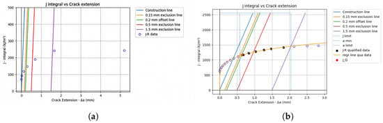
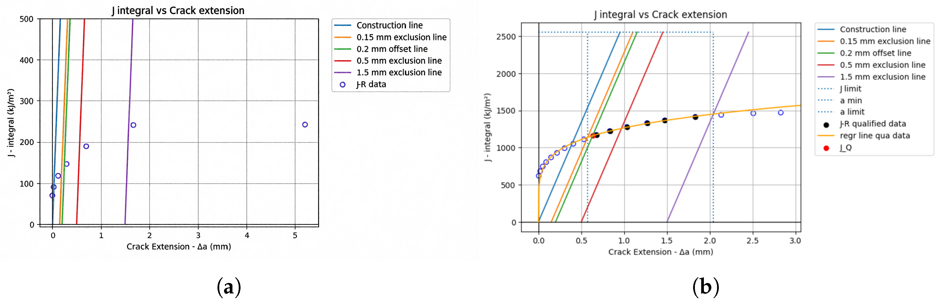
The ERC is used to evaluate if the propagation of the crack through material happened consistently under plastic conditions, or if it has portions where elastic rupture was predominant, as might be the case shown in Figure 1a. Due to the unstable propagation, there are not enough points in the qualified region, and the points are not equally spaced. Therefore, the test is invalid, and test repetition or a multiple-specimen-test approach is required. In comparison with Figure 1b, the amount of points allow for the construction of the regression curve.
Figure 1.
J-Integral curves for FT tests as example of (a) unstable crack propagation and (b) estable crack propagation.
Avoiding the unnecessary repetition of fracture toughness tests at 4 K is environmentally and economically preferable because doing so reduces material consumption, helium usage, and schedule impact. As with any J-test at 4 K, a post-processing procedure is required to assess the crack-size compliance estimation against the actual crack size. ERC, applied as a post-processing tool when a qualified J–R curve cannot be constructed, allowing toughness values to be obtained from tests that would otherwise be reported as invalid under ASTM E1820, thus reducing the need for repeat tests in some campaigns.
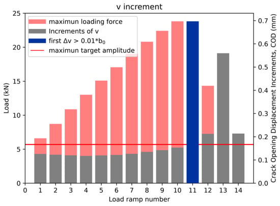
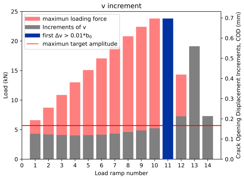
We know that the distance between points should be similar, as the control of the tests is performed targeting a maximum value of specimen aperture. During loading, the fast response and continuous live monitoring of crack openings via high-frequency data acquisition using a crack mouth opening displacement (CMOD) extensometer ensure that the system stops loading and begins unloading when the crack opening displacement (COD or v) reaches the target value (typically < 0.01 * ), down to 50 % of the previous loading ramp. Materials exhibiting UCP will eventually have a loading where the crack unexpectedly increases well beyond the maximum targeted value ( > 0.01 ), as shown in Figure 2, where the eleventh ramp presents a clear value of the COD well beyond the maximum allowed target.
Figure 2.
Example of a maximum load and for each loading ramp during the J-test of FXM-19.
The limit was not arbitrarily chosen; it is consistent with the maximum allowed increment before the unloading is initiated as the protocol defined by ASTM E1820 [10]. In C(T) specimens, the initial ligament is oriented normal to the direction of the CMOD extensometer displacement, and the initial extensometer separation is 2.5 mm. Typical DPF strain increments vary as a function of the strain rate, and generally <1% (so , which is considerably smaller than the displacement) increments typically associated with true unstable crack propagation and the limit previously mentioned.
In strict application of the standard protocol, CMOD increments below this threshold are associated with controlled stable tearing; thus, if remains below , the event cannot be classified as macroscopic UCP within the E1820 protocol and is treated as part of stable crack growth in our analysis.
Theoretically, an event with and could occur. However, in such a case the crack extension remains small and the material continues to sustain plastic deformation without a significant, uncontrolled increase in crack opening; these events do not correspond to the type of macroscopic UCP that undermines J–R curve construction and are intentionally treated as part of stable tearing in our analysis. In practice, ERC focuses on the loading ramp where the limit is first exceeded and combines this displacement-based indicator with the F criterion and the failure of J–R construction, reducing the risk of misclassifying pure DPF as UCP.
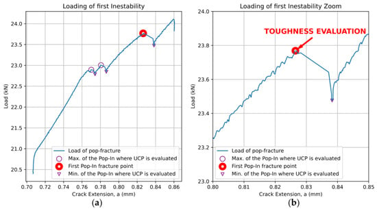
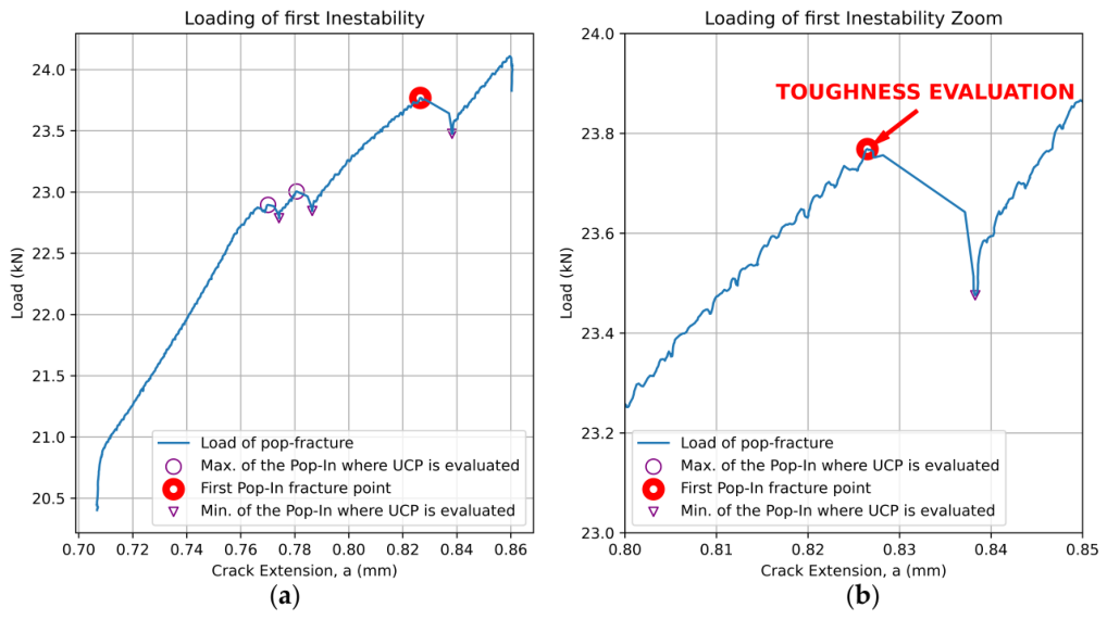
Then, the ERC evaluates the earliest event where F is greater than 0.05 in the first loading where , as shown in Figure 3, only if the J–R curve cannot be constructed.
Figure 3.
Example of a load ramp surpassing the threshold: (a) Full ramp. (b) Zoom-in on the region of interest.
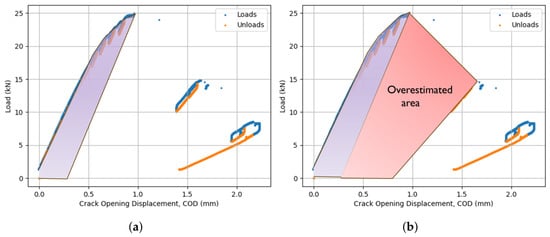
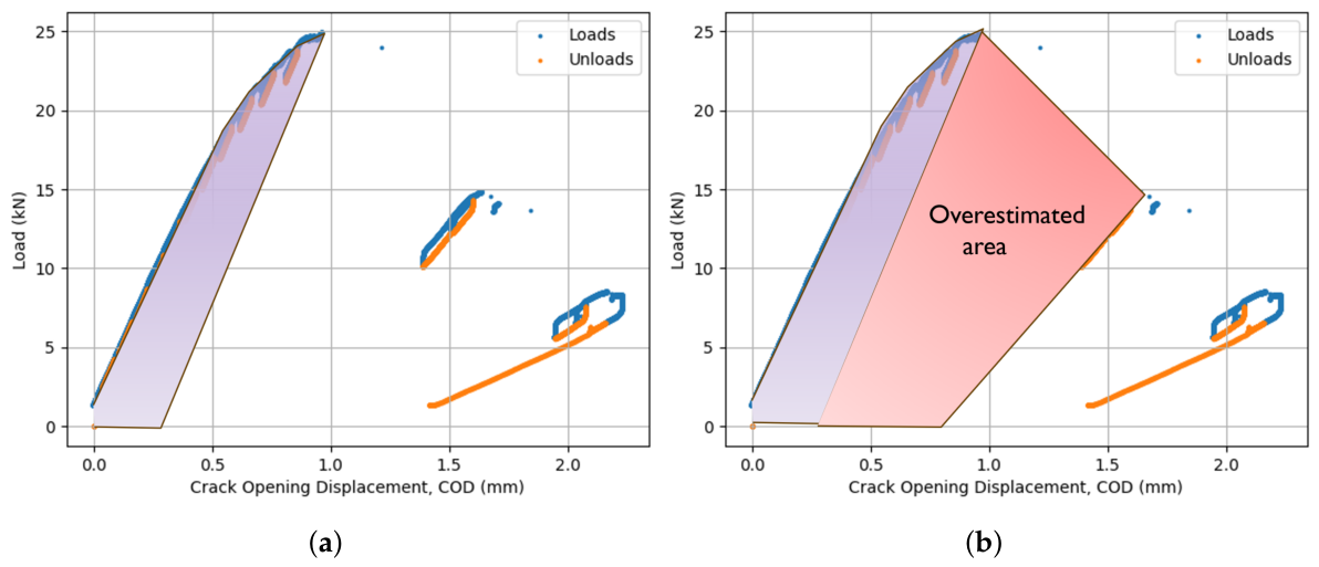
This evaluation not only improved the number of valid tests for materials with this behaviour, but it is also safer than trying to obtain the value using a regression line with insufficient or invalid points on the J-integral curve. A simple visualization of this is presented in Figure 4; it presents toughness as the area below the curve up to the two evaluation points obtained using the ERC (Figure 4a) and how toughness can be overestimated when invalid data points are used (Figure 4b).
Figure 4.
The classic simplification of visualizing the toughness as the area below the curve using the (a) ERC approach and (b) invalid points.
4. Materials and Methods
4.1. Materials
Two austenitic stainless steels were investigated: FXM-19 (Nitronic 50), a nitrogen-strengthened, precipitation-hardening austenitic stainless steel with composition ranges within ASTM A276/A276M [11], and 316LNH (1.4429), a low-carbon variant of 316LN with enhanced nitrogen content (0.18–0.22% N) at the upper limits of ASTM A276/A276M. This grade has been used in the manufacture of ITER toroidal field coil cases [12,13].
For a more representative approach, specimens were extracted from large forged products with dimensions up to 5 m × 1 m × 0.4 m.
4.2. Methods
All characterization was performed at 4 K. To characterize the materials at 4 K, compact tension specimens (CT-40) and round specimens with a diameter of 7 mm were prepared according to ASTM E1820 [10] and ASTM E1450 [14], respectively.
4.2.1. Tensile Test at 4 K
This method allowed for the determination of key mechanical properties, including the yield strength (Rp02), ultimate tensile strength (Rm), and elongation after break (EaB) according to ASTM E1450 [14]. Tests were performed at a strain rate of 2.5 10−3 s−1 in a Zwick-Roell Z250 universal testing machine equipped with a cryostat capable of performing the test up to 100 kN [15].
4.2.2. Fracture Toughness Testing at 4 K
Elastic–plastic fracture toughness tests (J-tests) are used when the material response to crack propagation involves significant plastic deformation. In this study, a single specimen and the unloading compliance method for crack length estimation was employed to ensure reliable FT data under cryogenic conditions.
However, this test was limited to Mode I (opening mode), where the principal load is applied normal to the crack plane. This test, when performed at 4 K, presented some particularities that must be addressed.
The resistance to crack extension is typically characterized by a monotonically increasing relationship between load and crack extension. Nevertheless, at cryogenic temperatures, ANCE manifests as negative offsets in crack extension measurements during unloading-compliance testing. These anomalies are therefore not only attributed to a single source or other several factors, including testing fixture misalignment, electronic noise, or signal non-linearity [4] but also to increased stiffness of the material and test system at 4 K.
The aim of this work is not to perform a mechanistic analysis of ANCE but to treat its effect consistently on a corrected crack length basis. To this end, we adopted the Nyilas–Weiss approach, which translates the crack growth initiation point to the blunting line using the minimum compliance (maximum stiffness) recorded during the test, irrespective of whether that corresponds to an exact experimental data point [6]. Alternative procedures exist, such as the JIS Z2284 approach in which the minimum recorded crack length point is translated to the blunting line [5], and we note that our choice is driven by robustness and consistency across the full temperature range rather than by an assumption about a single physical cause of ANCE. ANCE correction and crack propagation instabilities are two different and independent phenomena: ANCE is treated first to obtain a consistent crack extension history, and UCP is subsequently treated to identify the onset of unstable crack propagation in the presence of DPF.
Another phenomenon that is impacting the proper characterization of the toughness is the discontinuous plastic flow (DPF). The characteristic serrations observed in the stress–strain curves in the plastic regime occur below a threshold temperature () due to the lack of thermal energy needed to generate and move dislocations. is strongly dependent on material and can reach values as high as 35 K for austenitic stainless steels. The DPF is also strain-rate-sensitive; the severity of the drop in stress is more important at smaller strain rates, which are needed during cryogenic testing [7].
In some materials like FXM-19, this behaviour coexists with the unstable propagation of the crack front itself. In others, like 316LNH, it only presents DPF. However, if we apply the instability index F, as described in ASTM E1820 [10],
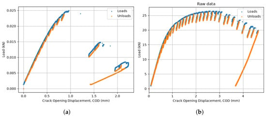
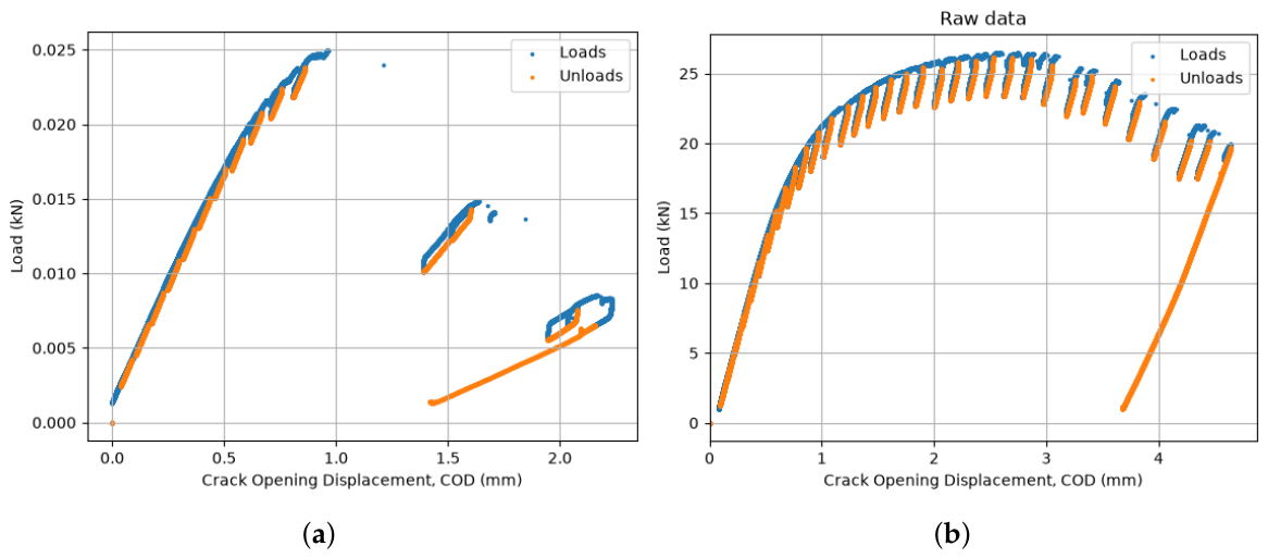
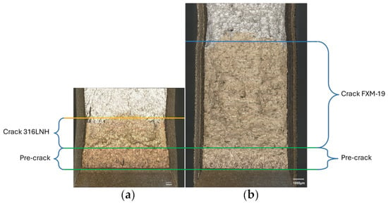
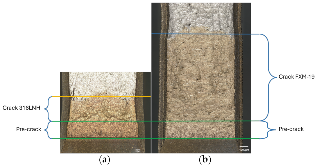
both materials exhibit UCP due to the false evaluation of DPF events, where F can be greater than 0.05. The index F and the limit were not introduced empirically in this work but were adopted directly from the standard, where F is indicative of instability in elastic–plastic fracture toughness tests. Within the scope of ASTM E1820, F is intended to be generic and independent of the specific material or machine, provided that the test is performed in accordance with the validity limits. We note that F can be influenced by data quality (noise level, stiffness resolution, sampling frequency), especially under 4 K conditions, where system stiffness is high and ANCE/DPF may distort the compliance signal. This leads to the current general practice at 4 K of ignoring this criterion due to the lack of useful tools available for evaluating the serrations. A criterion that assesses whether rupture occurs elastically is needed because, as shown in Figure 5, the two materials have completely different behaviour and fracture surfaces (Figure 6) but are being treated the same way.
Figure 5.
Load–unload curves during the FT tests of example specimens of (a) FXM-19 and (b) 316LNH.
Figure 6.
Example of typical surface fractures for (a) 316LNH and (b) FXM-19 after FT testing at 4 K.
Therefore, an Elastic-Rupture Criterion (ERC) can aid the decision-making process, since the ASTM E1820 criterion for unstable crack propagation is currently ignored when a material presents DPF.
5. Conclusions
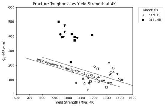
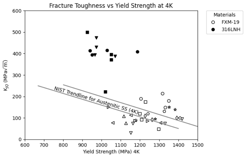
The relationship between fracture toughness () and yield strength at 4 K, as presented in Figure 7, reveals important insights into the performance of FXM-19 and 316LNH austenitic stainless steels under cryogenic conditions.
Figure 7.
Comparison between FXM-19 and 316LNH results against the NIST trendline for austenitic stainless steels.
The results reaffirm the well-established trade-off between yield strength and fracture toughness in metallic materials. The NIST trendline for austenitic stainless steels at 4 K captures this general behaviour, showing that higher yield strength comes at the expense of reduced toughness [16]. Against this benchmark, 316LNH demonstrates exceptional performance, with most data points positioned well above the NIST trendline. This indicates that 316LNH achieves a superior balance between strength and toughness compared to FXM-19, which performs as expected, and its values are aligned with the trend line.
The ERC method reliably produces valid results according to ASTM E1820 requirements. This represents a breakthrough for characterizing austenitic stainless steels that exhibit UCP at 4 K.
It should be emphasized that ERC, as implemented here, does not prevent UCP or control the test in real time; integrating ERC-type logic into modern test-control systems that display J versus online is identified as a promising direction for future work that lies beyond the scope of the present study.
This methodology can nevertheless be applied to any material that exhibits discontinuous plastic flow at any given temperature.
Author Contributions
E.R.C., I.A.S., S.S. and M.K.: conceptualization; E.R.C. and B.R.-P.: data curation; E.R.C., I.A.S., B.R.-P., S.S. and E.M.R.N.: formal analysis; E.R.C. and B.R.-P.: software; E.R.C., I.A.S., B.R.-P., E.M.R.N., S.S. and M.K.: validation; E.M.R.N., S.S. and M.K.: supervision; E.R.C., B.R.-P. and E.M.R.N.: visualization; E.R.C.: investigation, methodology, and writing—original draft; I.A.S., B.R.-P., E.M.R.N., S.S. and M.K.; writing—review/editing and project administration. All authors have read and agreed to the published version of the manuscript.
Funding
This research received no external funding.
Institutional Review Board Statement
Not applicable.
Data Availability Statement
The data presented in this study are available on request from the corresponding author due to confidentiality agreements and ongoing commercial considerations.
Acknowledgments
The authors thank Rolf Kind GmbH for kindly providing the materials used in this study.
Conflicts of Interest
Author Enrique Rodriguez Castro was employed by the company Foselev Suisse S.A. and author Markus Kind was employed by the company Rolf Kind GmbH. The remaining authors declare that the research was conducted in the absence of any commercial or financial relationships that could be construed as a potential conflict of interest.
Abbreviations
The following abbreviations are used in this manuscript:
| LHC | Large Hadron Collider |
| FCC | Face-Centered Cubic |
| ANCE | Apparent Negative Crack Extension |
| UCP | Unstable Crack Propagation |
| Rp02 | Yield Strength |
| Rm | Ultimate Tensile Strength |
| EaB | Elongation after Break |
| FT | Fracture Toughness |
| DPF | Discontinuous Plastic Flow |
| ERC | Elastic-Rupture Criterion |
| COD | Crack Opening Displacement |
| CMOD | Crack Mounth Oppening Displacement |
| NIST | National Institute of Standards and Technology |
References
- Geng, S. An Overview of the ITER Project. J. Phys. Conf. Ser. 2022, 2386, 012012. [Google Scholar] [CrossRef] [Scilit]
- Creely, A.J.; Greenwald, M.J.; Ballinger, S.B.; Brunner, D.; Canik, J.; Doody, J.; Fülöp, T.; Garnier, D.T.; Granetz, R.; Gray, T.K.; et al. Overview of the SPARC tokamak. J. Plasma Phys. 2020, 86, 865860502. [Google Scholar] [CrossRef] [Scilit]
- Brüning, O.; Burkhardt, H.; Myers, S. The large hadron collider. Prog. Part. Nucl. Phys. 2012, 67, 705–734. [Google Scholar] [CrossRef] [Scilit]
- ISO 12135:2016(E); Metallic Materials—Unified Method of Test for the Determination of Quasistatic Fracture Toughness. International Organization for Standardization: Geneva, Switzerland, 2016.
- JIS Z 2284:1998; Method of Elastic-Plastic Fracture Toughness JIC Testing for Metallic Materials in Liquid Helium. Japanese Standard Association 2000: Tokyo, Japan, 1998.
- Weiss, K.; Nyilas, A. Specific aspects on crack advance during J-test method for structural materials at cryogenic temperatures. Fatigue Fract. Eng. Mater. Struct. 2006, 29, 83–92. [Google Scholar] [CrossRef] [Scilit]
- Marcinek, D.J. Model of Discontinuous Plastic Flow at Temperature Close to Absolute Zero. Ph.D. Thesis, Cracow University of Technology, Kraków, Poland, 2016. [Google Scholar]
- Rodriguez Castro, E. Mechanical and Metallurgical Assessment of Austenitic Stainless Steel as Structural Materials for Superconducting High Field Magnets at Cryogenic Temperature. Ph.D. Thesis, CERN, Geneva, Switzerland, 2025. [Google Scholar] [CrossRef]
- ASTM E1823-21; Standard Terminology Relating to Fatigue and Fracture Testing. ASTM Compass: West Conshohocken, PA, USA, 2023. [CrossRef] [Scilit]
- ASTM E1820-20a; Standard Test Method for Measurement of Fracture Toughness. ASTM International: Philadelphia, PA, USA, 2020. [CrossRef] [Scilit]
- A276/A276M-16a; Standard Specification for Stainless Steel Bars and Shapes. ASTM Compass: West Conshohocken, PA, USA, 2017. [CrossRef] [Scilit]
- Oshikawa, T.; Funakoshi, Y.; Imaoka, H.; Iguchi, M.; Sakurai, T.; Nakahira, M. Manufacturing technology of 316LNH steel forging for ITER TF coil case. Teion Kogaku (Online) 2019, 54, 452–458. [Google Scholar] [CrossRef] [Scilit]
- Sakurai, T.; Umezawa, O. High-strength and high-toughness austenitic stainless steels based on type 316LN at 4.2 K. Cryogenics 2023, 136, 103762. [Google Scholar] [CrossRef] [Scilit]
- ASTM E1450-09; Standard Test Method for Tension Testing of Structural Alloys in Liquid Helium 1. ASTM Compass: West Conshohocken, PA, USA, 2017. [CrossRef] [Scilit]
- Aviles Santillana, I.; Betemps, R.; Gerardin, A.; Guinchard, M.; Langeslag, S.A.E.; Sgobba, S. Design and fabrication of a cryostat for low temperature mechanical testing for the Mechanical and Materials Engineering group at CERN. IOP Conf. Ser. Mater. Sci. Eng. 2015, 102, 012007. [Google Scholar] [CrossRef] [Scilit]
- NBSIR–80-1627; Materials Studies for Magnetic Fusion Energy Applications at Low Temperatures-III. National Bureau of Standards: Boulder, CO, USA, 1980. [CrossRef] [Scilit]

Disclaimer/Publisher’s Note: The statements, opinions and data contained in all publications are solely those of the individual author(s) and contributor(s) and not of MDPI and/or the editor(s). MDPI and/or the editor(s) disclaim responsibility for any injury to people or property resulting from any ideas, methods, instructions or products referred to in the content. |
© 2026 by the authors. Licensee MDPI, Basel, Switzerland. This article is an open access article distributed under the terms and conditions of the Creative Commons Attribution (CC BY) license.