


Abstract
The growing demand for reliable and sustainable renewable energy systems has increased interest in advanced electrical machines for wind energy conversion. Among these, the multiphase switched reluctance generator (SRG) offers advantages such as simple construction, low cost, high reliability, and inherent fault-tolerant capability. This paper presents the modeling and performance analysis of a four-phase switched reluctance generator under normal and fault conditions for wind energy applications. A MATLAB/Simulink model of the SRG integrated with a variable-speed wind turbine is developed to evaluate key performance parameters, including voltage, current, torque, speed, and flux characteristics. To investigate fault tolerance, phase exclusion faults are introduced and the generator performance is analyzed under degraded operating conditions. The simulation results show that the multiphase SRG continues operation even after the loss of one phase, although with increased torque ripple and current stress in the remaining phases. The implemented excitation and converter control strategies maintain system stability and acceptable performance under the investigated operating-speed conditions and phase-exclusion fault. The present work considers representative operating-speed conditions rather than a continuously varying wind-speed profile. The results demonstrate that multiphase SRGs provide reliable and robust operation for wind energy conversion systems. These characteristics make SRGs a potential option for wind-energy conversion applications.
1. Introduction
Research on permanent magnet (PM) machines has garnered concern and attention since the introduction of high energy PM materials, and this interest has persisted to this day. Recent developments have included taking advantage of internal permanent magnet synchronous machines’ (IPMSMs) power density limitations [1,2]. In particular, PM Vernier machines’ wide-speed range operation has been thoroughly studied for usage in electric cars and other variable-speed applications [3,4], including designs with very low wind speed for wind energy conversion WECs [5]. However, the drive system and the appropriate machine structure have become expensive, primarily because PM is used in areas where product cost is a key factor [6,7,8,9,10]. Trade disputes and end-use recycling are just two of the problems that must be resolved for the high energy rare-earth minerals that will be utilized to make PMs [11,12]. In a parallel universe, a new question has surfaced regarding the removal of rare-earth PM motors from wind energy conversion systems (WECSs) and electric vehicles (EVs), as well as what kind of motors can be utilized in their place [8,13]. More recently, due to reasons explained here, rare-earth high-energy PM-free machines such as wound rotor synchronous machines (WRSMs) [14,15,16], synchronous reluctance machines (Syn-RMs), and switched reluctance machines (SRMs) have been proposed as alternatives, due to their cheaper manufacturing and speed range capabilities with an extra degree of freedom for flux control that is better than the PM machines [17,18,19,20,21]. Furthermore, the machine has enhanced safety through direct field control during inverter fault conditions; the PM-less rotor shows no PM loss, and de-magnetization is not an issue [22,23,24].
The SRM represents a multiphase machine in many applications to take advantage of low cost, relatively safe failing currents, robustness to high temperature operation, and high torque-to-inertia ratio. SRMs rest on simple electromagnetic reluctance principles first proposed in the 19th century, but they only became practically viable once power electronics and digital control matured in the 1980s [25].
The SRM is used in the variable-speed wind energy conversion as a generator, that is, a switched reluctance generator (SRG) for its brushless, magnet-free construction, which gives it high robustness, low manufacturing cost, and strong fault tolerance, as an alternative to induction and PM machines.
A substantial body of work has focused on converter and control design such as advanced torque-control methods for multi-phase drives [26], while Omac [27] and Touati [28] used MATLAB 2026a-based and fuzzy super-twisting sliding-mode schemes, to improve SRG control under variable wind speed and suppress torque ripple. Scalcon et al. [29] provided a broad review of SRG fundamentals, control, and future trends in wind power, and Kiani et al. [30] combined model predictive control with Z-source converters to raise conversion efficiency and robustness. Related efforts have targeted multiphase winding and topology design [31], field-oriented control for multi-rotor systems [32], power-converter control for small-scale SRG wind systems [33], and model predictive control for multi-phase drives more broadly [34].
Recent research has also investigated advanced nonlinear and robust control techniques for electric-machine drives. Composite adaptive super-twisting sliding-mode control using barrier functions has been investigated to improve robustness and tracking performance in PM motor drives [35]. In addition, modified fixed-time extended-state-observer-based fixed-time sliding-mode control has been proposed to improve disturbance rejection and convergence characteristics in PMSM position servo systems [36]. These developments demonstrate the increasing use of robust nonlinear control techniques in electric-machine applications. However, the present study focuses on the modeling and fault-performance analysis of a multiphase SRG rather than the development of a new nonlinear control algorithm.
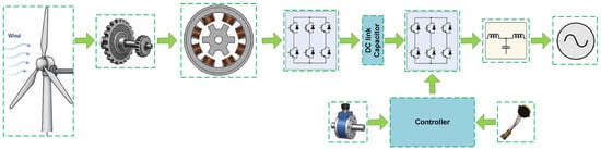
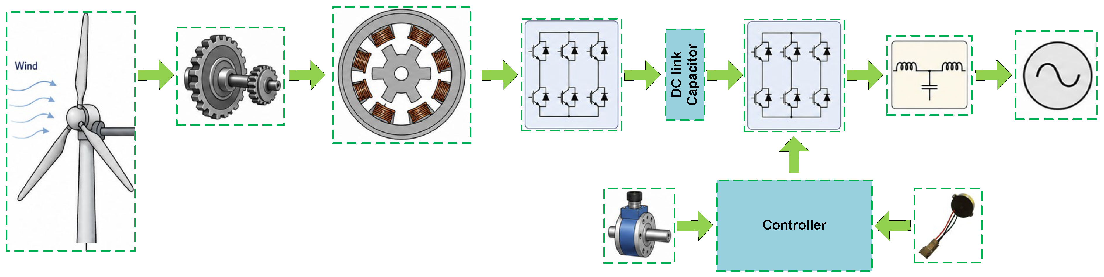
Fault tolerance is a recurring theme, since multi-phase SRGs can redistribute load across remaining phases when one fails, with limited disturbance to output [37]. Touati et al. [38] reviewed the state of the art and open challenges in SRG-based wind energy conversion. These developments prove the diversity and potential of SRGs in wind energy applications. In the context of innovative control strategies, fault-tolerant designs, and optimization techniques, SRGs play an important role in a global shift toward cleaner and more sustainable energy solutions. The group’s possible candidate is the SRG, which is made up of the controller, power converter, and SRG, as seen in Figure 1.
Figure 1.
Block-level architecture of the SRG-based wind energy conversion system, including the wind turbine, gearbox, sensing units, power converter, DC-link, inverter, and grid interface.
Figure 2 summarizes the energy conversion process in the proposed wind energy conversion system. Initially, the kinetic energy of the wind is captured by the turbine blades and converted into mechanical rotational power, which is transmitted through the gearbox to drive the SRG. The SRG converts the mechanical input into variable-frequency, variable-amplitude three-phase electrical power, whose characteristics depend on the rotor speed and excitation control [39]. This electrical power is then processed by the asymmetric SRG converter, which rectifies it into DC power while regulating the DC-link voltage. The DC-link capacitor smooths voltage fluctuations and provides a stable energy buffer between the generator-side converter and the grid-side inverter. Finally, the inverter converts the DC power into synchronized AC power with the required voltage and frequency for delivery to the utility grid or local AC loads through the LCL filter [33]. Operating parameters for simulations results are given in Table 1.
Figure 2.
Power conversion process of the SRG-based wind energy conversion system.
Table 1.
Design parameters of the machine system and control.
The objective of this work is to investigate the modeling and operating characteristics of a four-phase switched reluctance generator under normal and single-phase exclusion conditions for wind-energy conversion. The study focuses on the integration of the SRG, converter, controller, and wind-energy system within a common MATLAB/Simulink-2026a framework and examines the resulting voltage, current, torque, speed, and flux-linkage responses. The work is intended as a system-level assessment of the effect of phase exclusion rather than as the proposal of a new machine topology, fault-diagnosis algorithm, or advanced fault-tolerant controller.
2. Topology and Working Principles
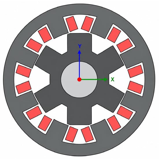
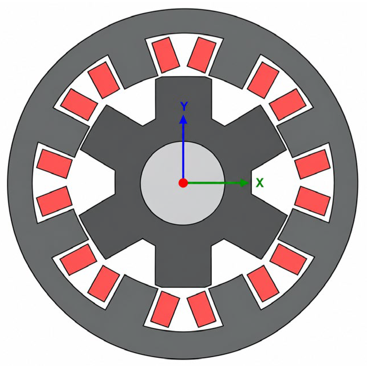
The rotor has many nonmagnetic poles, whereas the stator has three pole pairs that support the three motor windings. By activating a pair of stator poles, the motor pulls the nearest rotor poles toward alignment by applying force to them. The motor’s structure is depicted in Figure 3. This is the machine’s mathematical model as given below.
where v is the applied voltage; L is phase inductance; and R is the SRG’s winding resistance, which is assumed to be 2.5 ohms in the input data along with the flux, co-energy, and static torque input data that are required for the SRG model. Equation (1) can be written as (3) using a fundamental relationship between the flux linkage and current.
where θ is the rotor position, and the angular speed in rad/sec is represented by ω = dθ/dt. The induced electromotive force (EMF), resistive voltage drop, and inductive voltage drop, respectively, represent the applied voltage. Equation (4) multiplied by phase current i yields the breakdown of total power, vi.
Figure 3.
The 2D cross-sectional view of an SRG showing windings, and iron core.
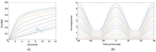
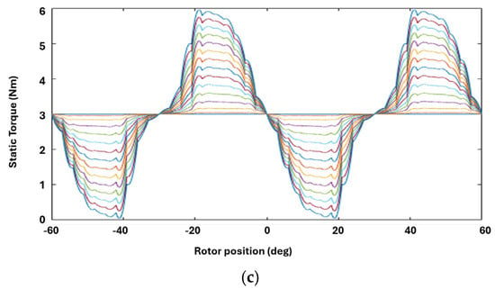
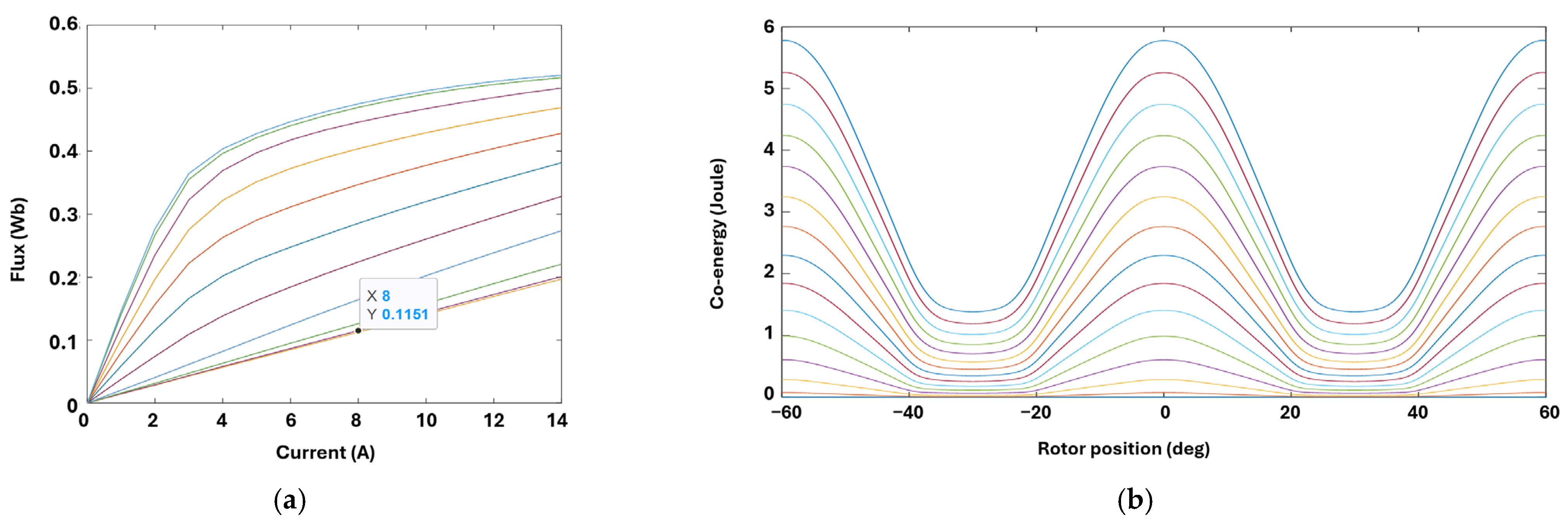
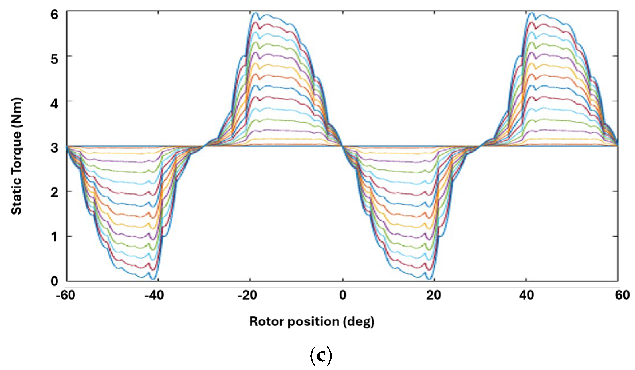
The nonlinear magnetic characteristics used in the simulation are represented through the relationship ψ = ψ (, θ), where ψ is the phase flux linkage, i is the phase current, and θ is the rotor position. The flux-linkage, co-energy, and static-torque data used in the model were adopted from the published SRM input-data set reported in [40]. These data are incorporated into the simulation as magnetic characteristic inputs and are used to determine the electromagnetic response as a function of current and rotor position. Thus, the model accounts for the nonlinear magnetic characteristics represented by the supplied data rather than assuming a constant inductance.
According to Equation (5), the total power is equal to the sum of the power loss, the rate at which stored magnetic energy increases, and the power that is transformed from electrical energy to mechanical output power. The equation provides the electromagnetic torque of SRG. The linear torque equation is
For the mechanical dynamics of the generator,
where combines the rotational inertia of the generator and mechanical system, is the applied mechanical torque, and is the viscous friction coefficient. To represent the nonlinear magnetic behavior of the SRG, the flux linkage is expressed as
For the nonlinear magnetic model, the magnetic co-energy is given by
The electromagnetic torque can then be obtained from
where the derivative is taken with respect to rotor position while keeping the phase current constant.
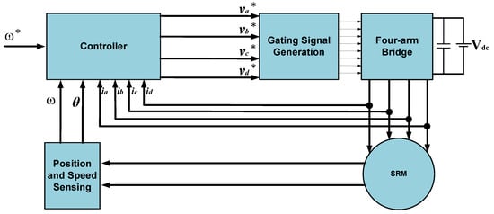
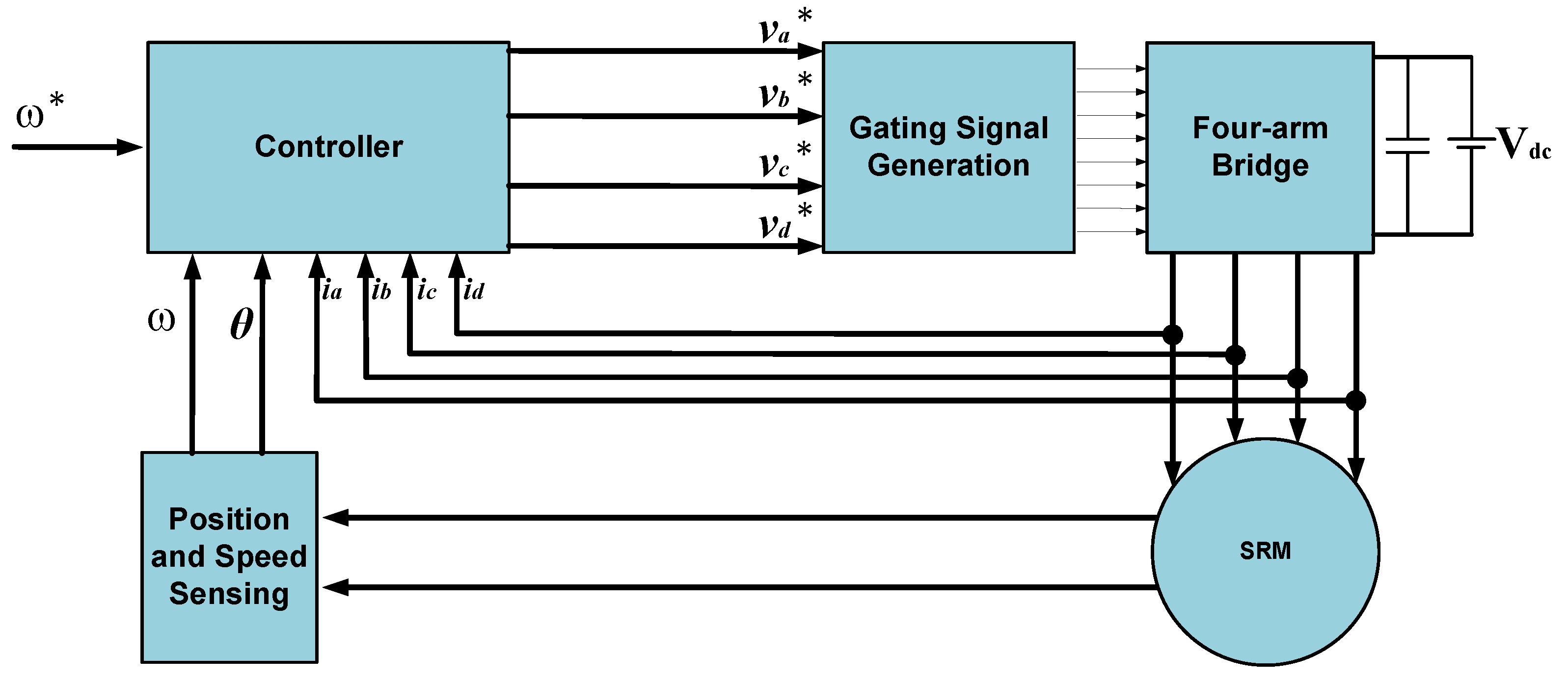
The drive consists of a four-phase SRG interfaced with the load through a four-arm asymmetric half-bridge converter, as illustrated in Figure 4. Each phase winding (A, B, C, D) is connected across one arm of the converter, with the two switches per leg (driving the “1” and “2” terminals of each phase) allowing independent excitation and de-excitation of the corresponding stator winding. The DC bus voltage source supplies the converter, while the phase currents on the primary legs (A1–D1) are monitored through the current-sensing block (Iabcd) before entering the machine; the return legs (A2–D2) connect directly to the generator. Because the SRG has no permanent magnets or rotor windings, torque (or, in generation mode, the induced EMF) is produced purely by the variation of phase inductance with rotor position as the salient rotor poles align with and depart from the excited stator poles. A rotor-position/speed sensor mounted on the shaft feeds the instantaneous angle (θ) and speed back to the control unit, which uses this information to determine the correct turn-on and turn-off angles for each phase and to regulate the switching of the converter accordingly. The control unit compares the measured speed against a reference command (ω*) and, through closed-loop excitation-angle and current control, adjusts the converter’s switching pattern to track the demanded operating point while keeping the torque ripple and phase current within acceptable limits. The resulting electrical and mechanical variables (phase voltages/currents, speed, and torque) are recorded through the measurement scopes for performance evaluation. This topology retains the inherent fault-tolerance, mechanical robustness, and magnet-free construction of the SRG while giving the control unit full independent control over each phase, which is essential for extracting stable power across the variable-speed operating range typical of wind energy conversion applications.
Figure 4.
The block diagram of SRG connected between wind turbine and load with the superscript * identifies reference parameters.
The converter control regulates the generator excitation according to the rotor operating condition. The speed-control loop compares the reference and measured rotor speeds and generates the corresponding current/excitation reference. The phase-current control regulates the excitation current of the active phases, while the excitation-angle control determines the appropriate switching interval for each phase. During the investigated phase-exclusion condition, the faulty phase is removed from excitation and the remaining phases continue to operate through the converter control system.
3. Simulation Modeling of Switched Reluctance Generator
The SRG system was implemented and simulated in MATLAB/Simulink. The simulation includes the wind-energy conversion system, converter, excitation control, and nonlinear SRG model. The initial conditions and operating conditions were selected according to the machine and system parameters listed in Table 1. The simulation results presented in this study were obtained using the numerical settings implemented in the developed Simulink model. Since a separate numerical time-step sensitivity study was not performed, numerical independence from the selected time step is not claimed. MATLAB is used for simulations. The general voltage equations of switched reluctance machines, which control the stator current of SRG, serve as the foundation for the created model. For simulation, flux, co-energy, and static torque, input data are used that are borrowed from a model in [40], as shown in Figure 5.
Figure 5.
Input data with different operating points of (a) flux with respect to current, (b) co-energy vs. rotor position, and (c) static torque vs. rotor position for simulation purposes.
The simulation study is limited to two representative operating-speed conditions and the investigated single-phase exclusion fault. Therefore, the results should be interpreted as a focused assessment of phase-exclusion behavior rather than a comprehensive evaluation of all possible wind-speed and fault conditions.
3.1. Output Voltage and Current Characteristics
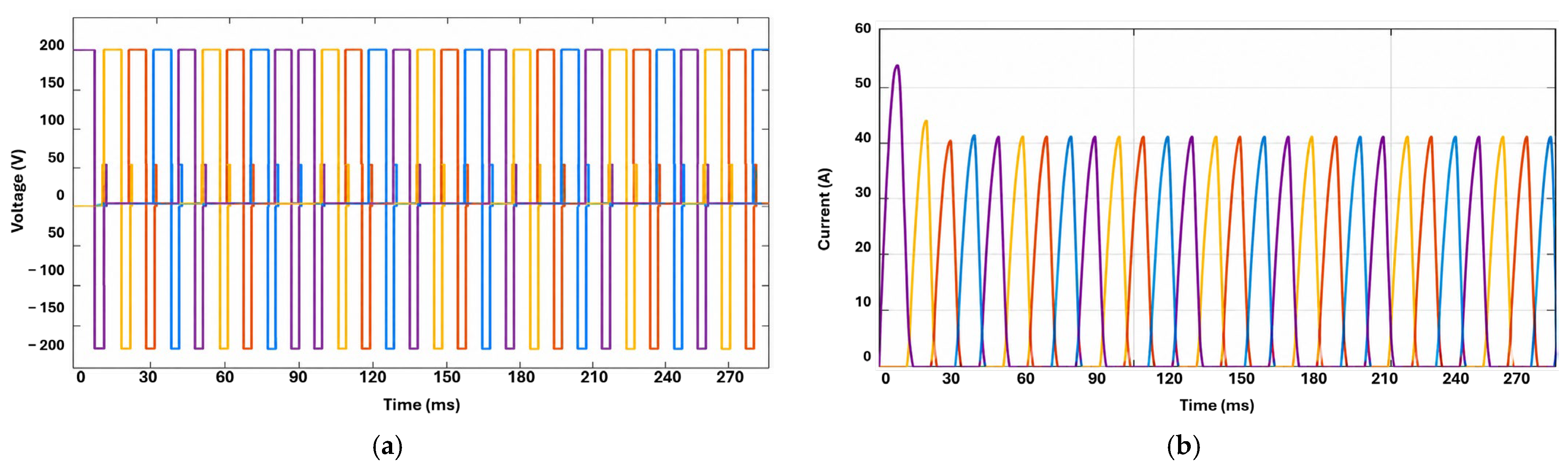
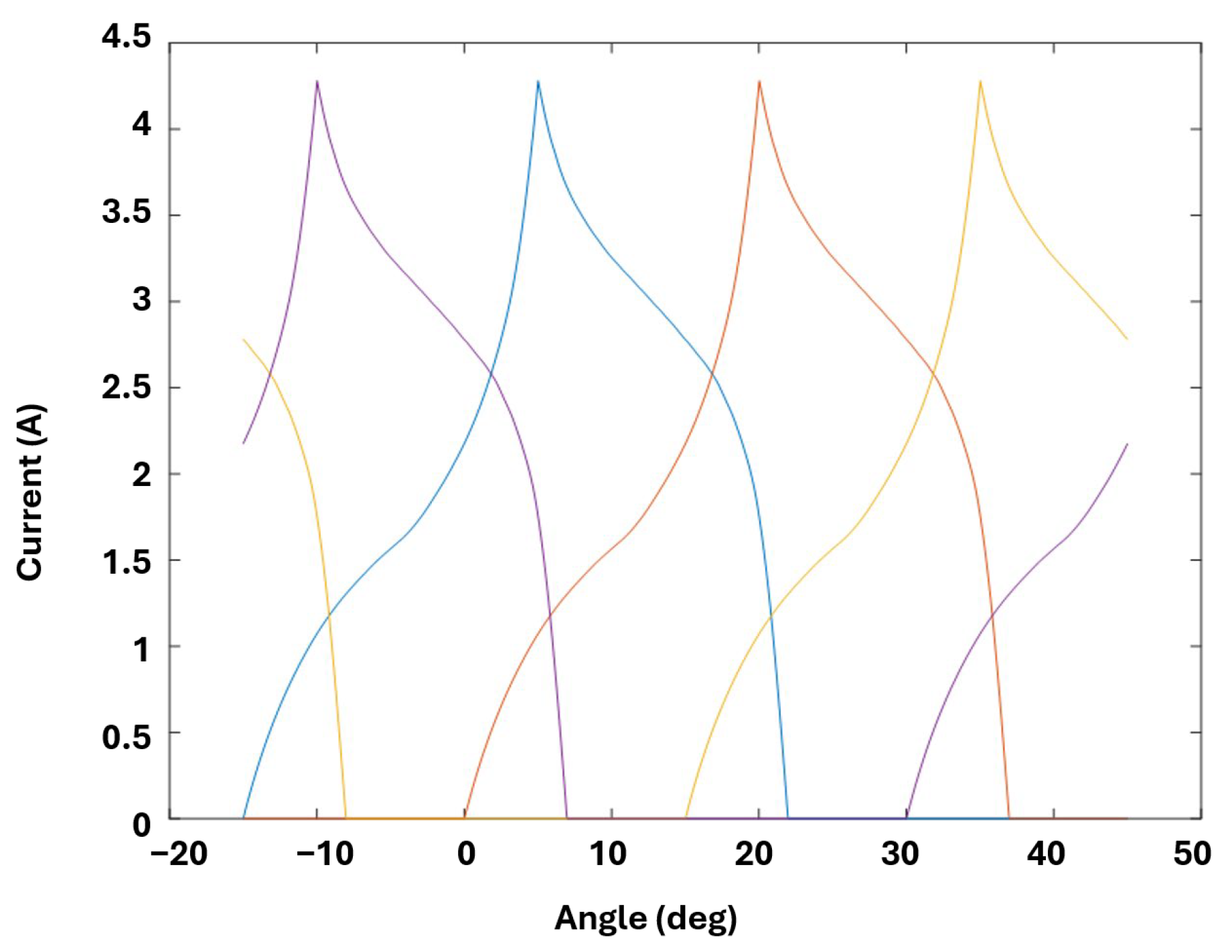
The SRG will show a brief response during startup, with the current overshooting before stabilizing. The strong initial electromagnetic torque required to overcome inertia and start the rotor movement is the cause of this overshoot. The power electronics controller plays a crucial part in this phase by regulating the current flowing through the stator windings to prevent overheating or system damage. In [41], a similar study is conducted showing that the transient characteristics are consistent with such experiments, confirming that the startup behavior complies with theoretical expectations. As a result, it shows an improvement in transient recovery time, which is essential for this kind of control technique to preserve system reliability. The output voltage and current waveform for four phases (purple phase A, dark yellow phase B, light yellow phase C, and blue phase D) are displayed in Figure 6.
Figure 6.
The output waveforms for four phases (a) voltage waveform and (b) current waveform.
3.2. Output Torque and Speed Analysis
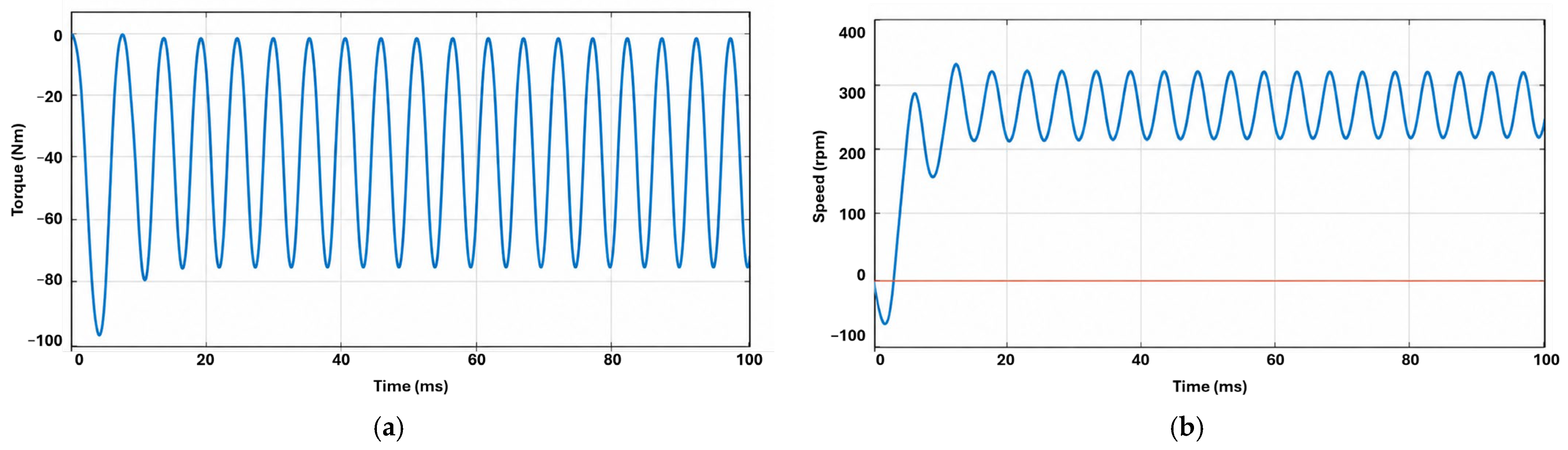
Since the instantaneous torque value varies significantly during phase transition, SRGs are designed with torque ripples. A four-phase half-bridge converter and ideal excitation timing made sure that the torque ripple was maintained to a minimum. While confirming the suitability of the chosen control approach, the torque curve is smooth with just slight oscillations. This has immediate consequences for wind turbine applications, where smoother torque ensures better mechanical stability and reduced wear on its components. The electromagnetic torque exhibits periodic oscillations associated with phase excitation and commutation. The observed torque response is used to evaluate the generator behavior under the investigated operating conditions. The overall torque and speed waveform is shown in Figure 7.
Figure 7.
The output SRG waveforms of (a) total torque and (b) speed.
4. Simulation Results for SRG in Wind Energy Systems
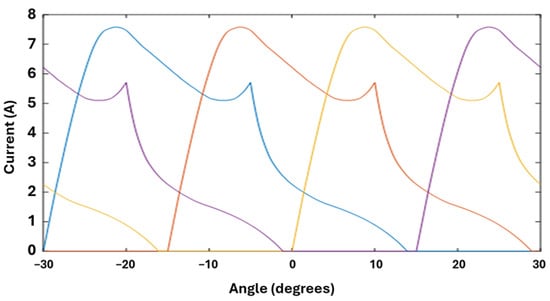
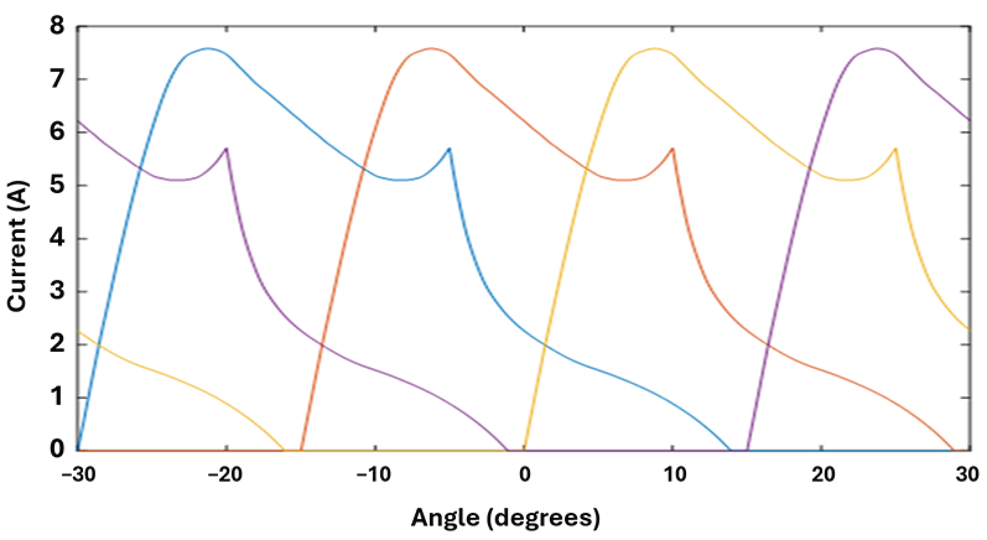
The simulation results characterize the output voltage and current of the SRG-based wind-energy conversion system. The SRG’s early excitation requirements create a large current inrush during the starting period. However, this current stabilizes and reaches stable values after the generator enters steady-state operation. The corresponding voltage profile verifies the excitation control circuit’s ability to handle the change and establishes consistency following the “startup.” Figure 8 displays the overall WEC current, whereas Figure 9 displays the output current waveforms of SRG in relation to phases.
Figure 8.
Total output currents with respect to each phase of the WEC system.
Figure 9.
Total generator current with respect to each phase.
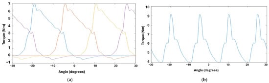
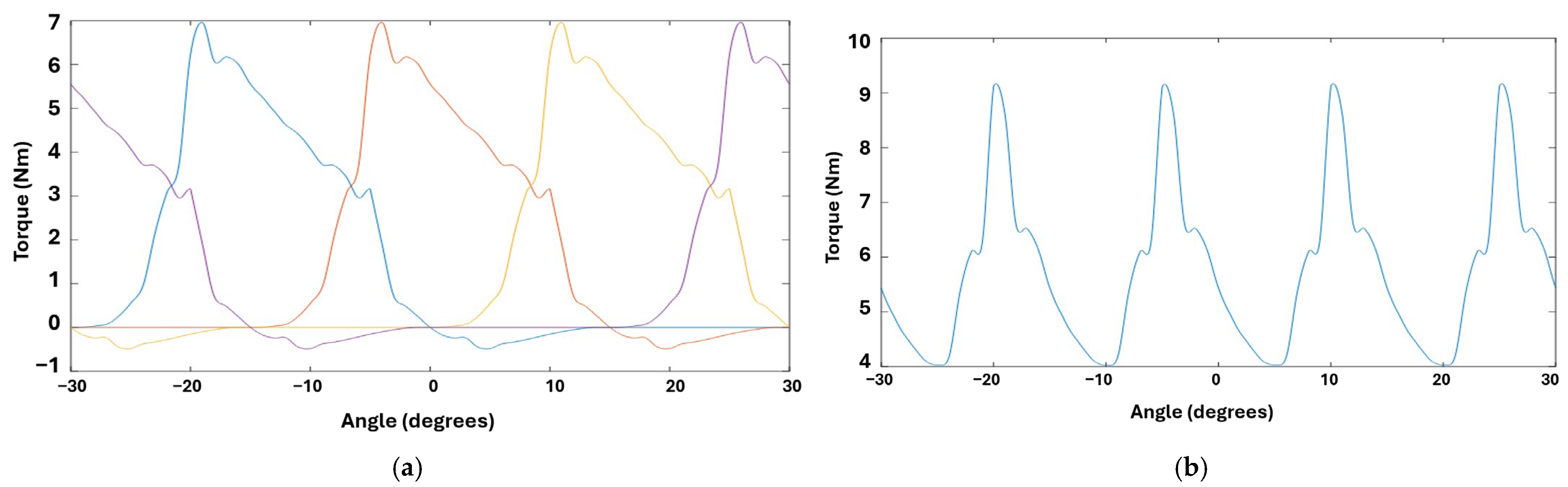
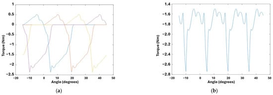
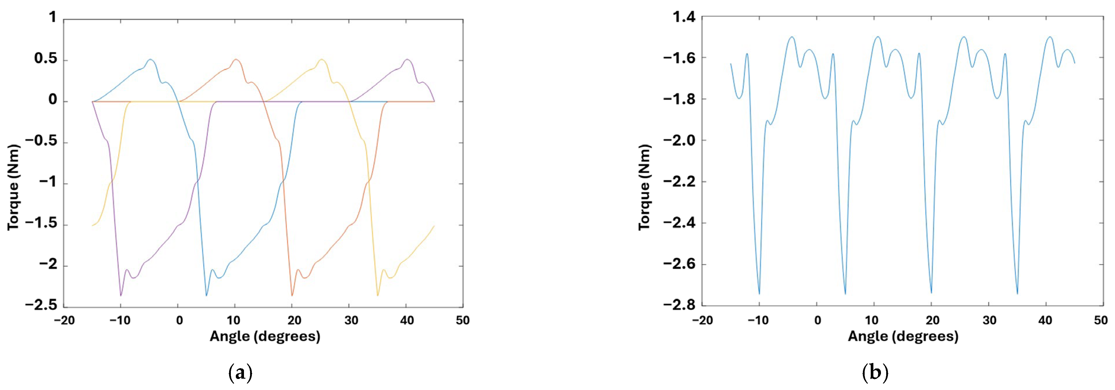
The output torque parameters of an SRG utilized in wind energy applications have a major impact on the efficiency, power generating capacity, and performance stability of the wind turbine system. Because SRGs can produce significant torque at low speeds, they are ideal for harnessing energy from low wind conditions. Reducing torque ripple, managing output torque, and adapting to varying wind speeds are all necessary for optimizing SRG performance. SRGs offer a dependable, efficient, and cost-effective substitute for wind energy production. The output torque waveforms of WEC and SRG are displayed in Figure 10 and Figure 11, respectively.
Figure 10.
WEC torque profile: (a) all phases individually and (b) total torque.
Figure 11.
Generator torque profile: (a) all phases individually and (b) total torque.
5. Performance Under Fault Conditions
Impact of Phase Exclusion on SRG Operation
Most of the information regarding an SRG’s dependability and fault-tolerant capacity is provided by its phase exclusion fault, which often occurs in a simulation environment. Unusual variations in torque, current stability, and overall system efficiency when one phase is removed are revealed by changes in the SRG’s operation characteristics. Following phase exclusion, the generator exhibits a transient change in electromagnetic torque and torque ripple as the remaining active phases respond to the loss of one phase. Their electromagnetic equilibrium is upset as a result of the load being redistributed among the remaining active phases.
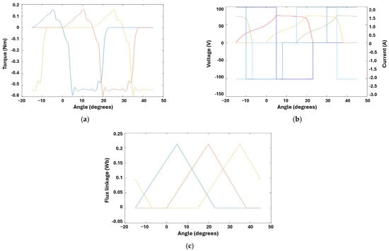
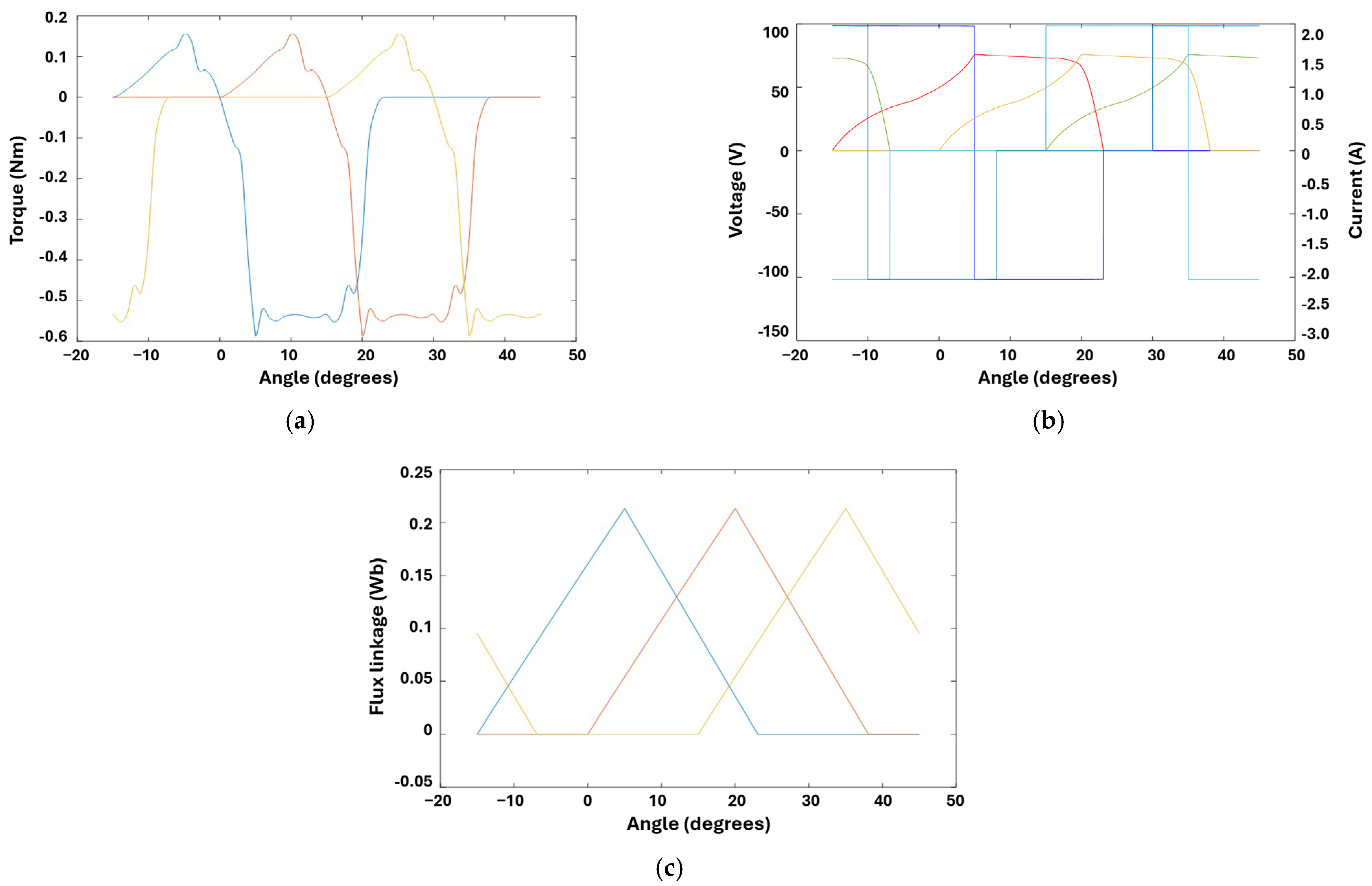
Phase exclusion results in higher current demands in active phases to compensate for the missed phase from the standpoint of current dynamics. The SRG will still function, albeit more slowly and with greater losses, because of its built-in fault tolerance. Because of the excitation control circuit, this guarantees that the system’s voltage stability is not jeopardized and that continuous functioning is maintained. Phase excitation techniques are optimal for recovering from a lost phase according to our overall analysis. In order to ensure sustained operation during fault conditions, advanced control solutions like adaptive excitation and dynamic load sharing have important roles to play in reducing the impact of phase exclusion. Additionally, current, voltage, torque, and flux profiles are displayed in Figure 12 after a failure develops on one phase while the other phases are operating.
Figure 12.
Under the fault condition when one phase is out and three phase results are shown for (a) the independent instantaneous torque profile, (b) currents and voltages, and (c) flux linkages.
The resilience of an SRG in wind applications is validated by the fault conditions. The outcomes are as follows: even if phase exclusion presents operational difficulties, SRG is still functional and has a major benefit over traditional devices like doubly-fed induction generators (DFIGs), which lack fault-tolerant features by design. In a simulation where dynamic load redistribution among remaining active phases ensures continuous operation, fault-tolerant behavior is demonstrated by continuous machine torque output. Table 2 lists the performance parameters of SRG under normal and fault conditions for comparison.
Table 2.
Performance parameters of SRG under normal value and fault condition value.
Following phase exclusion, the generator exhibits a transient change in torque and speed before reaching a new operating condition. The independent phase structure allows the remaining phases to continue excitation after the fault. Additionally, the simulation’s verification demonstrates that sophisticated excitation control circuits can significantly lessen the negative consequences of phase loss. The simulations emphasize how crucial it is to optimize the design parameters to be as fault-tolerant as possible by contrasting the outcomes with fault-free operations. This could involve adding more phases or using redundant windings, which improve the machine’s fault behavior and make SRGs appropriate for remote wind farms.
6. Conclusions
By assessing and improving multi-phase SR machines for wind energy applications, the aforementioned work advances machine technologies. The results characterize the changes in generator current, torque, speed, and voltage following single-phase exclusion. These advancements stimulate innovation in other renewable energy sectors and help the wind energy industry. One of the biggest issues with SR machines is torque ripple. To provide smoother torque production and improve the operational stability of wind turbines, this study methodically investigates multi-phase topologies and their mitigation of torque ripple. It helps remove one of the biggest obstacles to the widespread use of switching reluctance machines in high-performance applications.
The study’s findings have practical applications in addition to scholarly value. Future research topics include fault tolerance, dynamic load adaptation, and converter efficiency. Based on the study’s findings, industrial applications are created using reliable, affordable wind turbine systems that facilitate the integration of renewable energy into international power networks. The present study is limited to MATLAB/Simulink-based analysis, two representative operating-speed conditions, and a single-phase exclusion fault. Experimental validation, dynamic wind-speed operation, multiple-phase faults, and converter fault conditions were not considered. Future research can therefore focus on experimental validation, more comprehensive fault scenarios, and advanced fault-tolerant control strategies for multiphase SRG systems.
Author Contributions
Conceptualization, W.A.A.S. and G.J.S.; methodology, W.A.A.S., G.J.S. and Z.A.; software, W.A.A.S., G.J.S. and S.A.K.; validation, W.A.A.S. and Z.A.; formal analysis, W.A.A.S. and Z.A.; investigation, W.A.A.S., G.J.S. and Z.A.; resources, W.A.A.S., G.J.S., Z.A., M.S. and S.A.K.; data curation, W.A.A.S., Z.A. and M.S.; writing—original draft preparation, W.A.A.S. and G.J.S.; writing—review and editing, W.A.A.S., G.J.S., Z.A., M.S. and S.A.K.; visualization, W.A.A.S., G.J.S. and M.S.; supervision, G.J.S., Z.A. and S.A.K.; project administration, W.A.A.S., G.J.S., Z.A., M.S. and S.A.K.; and funding acquisition, Z.A., M.S. and S.A.K. All authors have read and agreed to the published version of the manuscript.
Funding
This research received no external funding.
Institutional Review Board Statement
Not applicable.
Informed Consent Statement
Not applicable.
Data Availability Statement
The data will be made available upon request.
Conflicts of Interest
The authors declare no conflicts of interest.
Abbreviations
The following abbreviations are used in this manuscript.
| SRM | Switched reluctance machine |
| SRG | Switched reluctance generator |
| PM | Permanent magnet |
| IPMSM | Interior permanent magnet synchronous machine |
| WEC | Wind energy conversion |
| WRSM | Wound rotor synchronous machine |
| Syn-RM | Synchronous reluctance machine |
| AC | Alternating current |
| EMF | Electromotive force |
| DC | Direct Current |
| LCL | Inductor-capacitor-inductor |
| DFIG | Doubly-fed induction generators |
References
- Scaglione, G.; Nevoloso, C.; Schettino, G.; Tommaso, A.O.D.; Miceli, R. A Novel Multiobjective Finite Control Set Model Predictive Control for IPMSM Drive Fed by a Five-Level Cascaded H-Bridge Inverter. IEEE J. Emerg. Sel. Top. Power Electron. 2024, 12, 1959–1973. [Google Scholar] [CrossRef] [Scilit]
- Rahman, M.M.; Uddin, M.N. Third harmonic injection based nonlinear control of IPMSM drive for wide speed range operation. In Proceedings of the 2017 IEEE Industry Applications Society Annual Meeting, Cincinnati, OH, USA, 1–5 October 2017; pp. 1–8. [Google Scholar] [CrossRef] [Scilit]
- Zhao, X.; Niu, S. A New Slot-PM Vernier Reluctance Machine with Enhanced Zero-Sequence Current Excitation for Electric Vehicle Propulsion. IEEE Trans. Ind. Electron. 2020, 67, 3528–3539. [Google Scholar] [CrossRef] [Scilit]
- Arif, A.; Baloch, N.; Kwon, B.-I. Winding Switching and Turn Switching in Permanent Magnet Vernier Machines for Wide Speed Range Operation and High Efficiency. IEEE Access 2019, 7, 55344–55357. [Google Scholar] [CrossRef] [Scilit]
- Arif, A.; Baloch, N.; Kwon, B.-I. Design and optimization of a Low-RPM Neodymium permanent magnet synchronous generator for two-stage vertical-axis wind turbines in low-speed applications. Wind Eng. 2025, 50, 351–371. [Google Scholar] [CrossRef] [Scilit]
- Chai, W.; Cai, Z.; Kwon, B.-I.; Kwon, J.-W. Design of a Novel Low-Cost Consequent-Pole Permanent Magnet Synchronous Machine. IEEE Access 2020, 8, 194251–194259. [Google Scholar] [CrossRef] [Scilit]
- Sirewal, G.J.; Bukhari, S.S.H. Cost-Effective Scheme for a Brushless Wound Rotor Synchronous Machine. World Electr. Veh. J. 2021, 12, 194. [Google Scholar] [CrossRef] [Scilit]
- Edmondson, J. Will Rare-Earths Be Eliminated in Electric Vehicle Motors? Available online: https://www.idtechex.com/en/research-article/will-rare-earths-be-eliminated-in-electric-vehicle-motors/21972 (accessed on 15 September 2026).
- Bukhari, S.S.; Sirewal, G.J.; Chachar, F.A.; Ro, J.-S. Brushless Field Excitation Scheme for Wound Field Synchronous Machines. Appl. Sci. 2020, 10, 5866. [Google Scholar] [CrossRef] [Scilit]
- Sirewal, G.J.; Ayub, M.; Kwon, B.-I. A Self-Excitation Scheme for a Brushless Synchronous Generator. In Proceedings of the 2019 10th International Conference on Power Electronics and ECCE Asia (ICPE 2019—ECCE Asia), Busan, Republic of Korea, 27–30 May 2019; pp. 1227–1232. [Google Scholar] [CrossRef] [Scilit]
- Kaya, E.E.; Kaya, O.; Stopic, S.; Gürmen, S.; Friedrich, B. NdFeB Magnets Recycling Process: An Alternative Method to Produce Mixed Rare Earth Oxide from Scrap NdFeB Magnets. Metals 2021, 11, 716. [Google Scholar] [CrossRef] [Scilit]
- Rare Earths Trade Dispute. Wikipedia. Available online: https://en.wikipedia.org/wiki/Rare_earths_trade_dispute (accessed on 15 September 2026).
- Seyedi, S.M.; Talebi, D.; Toliyat, H.A. A PM-Free Brushless Synchronous Machine with a Novel Compensated Wound-Field Excited by Modulated Rotating Magnetic Flux. IEEE Trans. Energy Convers. 2024, 39, 2068–2080. [Google Scholar] [CrossRef] [Scilit]
- Abbas, Z.; Sirewal, G.J.; Hur, J. Harmonic-Excited Closed-Slot Brushless Wound Rotor Synchronous Machine with Reduced Torque Ripple. IEEE Access 2026, 14, 80624–80635. [Google Scholar] [CrossRef] [Scilit]
- Prakht, V.; Dmitrievskii, V.; Kazakbaev, V.; Goman, V.; Sun, X. Design Optimization of a Harmonic-Excited Synchronous Machine Using the Nelder–Mead Algorithm with an Internal Optimization Procedure. IEEE Open Access J. Power Energy 2026, 13, 497–506. [Google Scholar] [CrossRef] [Scilit]
- Seyedi, S.M.; Hurt, S.E.; Talebi, D.; Toliyat, H.A. A Review of Excitation Technologies in Rare-Earth Free Wound Rotor Synchronous Machines for Transportation Electrification. In Proceedings of the 2026 IEEE Transportation Electrification Conference & Expo (ITEC) & Electric Aircraft Technologies Symposium (EATS) (ITEC+EATS), Novi, MI, USA, 10–12 June 2026; pp. 1–6. [Google Scholar] [CrossRef] [Scilit]
- Lipo, T.A.; Du, Z.S. Synchronous motor drives-a forgotten option. In Proceedings of the 2015 Intl Aegean Conference on Electrical Machines & Power Electronics (ACEMP), 2015 Intl Conference on Optimization of Electrical & Electronic Equipment (OPTIM) & 2015 Intl Symposium on Advanced Electromechanical Motion Systems (ELECTROMOTION), Side, Turkey, 2–4 September 2015; pp. 1–5. [Google Scholar] [CrossRef] [Scilit]
- Chen, H.; Tang, J.; Liu, Y.; Jiang, B.; Boscaglia, L. Electromagnetic Performance Investigation of a Brushless Electrically Excited Synchronous Machine for Long-Distance Heavy-Duty Electric Vehicles. IEEE Trans. Transp. Electrif. 2025, 11, 225–235. [Google Scholar] [CrossRef] [Scilit]
- Akuru, U.B.; Ullah, W.; Okojie, D.E.; Masisi, L.; Idoko, H.C.; Khan, F. Comparative Performance Evaluation, Prototyping and Experimentation of the Double-Stator Wound-Field Flux Switching Machine. IEEE Trans. Ind. Appl. 2024, 60, 6706–6714. [Google Scholar] [CrossRef] [Scilit]
- Nguyen, M.-D.; Hoang, D.-T.; Kim, S.-M.; Jung, W.-S.; Shin, K.-H.; Kim, Y.-J.; Choi, J.-Y. Nonlinear Modeling and Analysis Considering Coupling Stator Flux of Wound-Rotor Synchronous Motors. In Proceedings of the 2024 International Conference on Electrical Machines (ICEM), Torino, Italy, 1–4 September 2024; pp. 1–7. [Google Scholar] [CrossRef] [Scilit]
- Li, Y.; Wang, Y.; Zhang, Z.; Li, J. Investigation and Development of the Brushless and Magnetless Wound Field Synchronous Motor Drive System for Electric Vehicle Application. World Electr. Veh. J. 2023, 14, 81. [Google Scholar] [CrossRef] [Scilit]
- Dorrell, D.G. Are wound-rotor synchronous motors suitable for use in high efficiency torque-dense automotive drives? In Proceedings of the IECON 2012—38th Annual Conference on IEEE Industrial Electronics Society, Montreal, QC, Canada, 25–28 October 2012; pp. 4880–4885. [Google Scholar] [CrossRef] [Scilit]
- Laldin, O.; Sudhoff, S.D.; Pekarek, S. An Analytical Design Model for Wound Rotor Synchronous Machines. IEEE Trans. Energy Convers. 2015, 30, 1299–1309. [Google Scholar] [CrossRef] [Scilit]
- Liu, W.; Lipo, T.A. Saliency enhancement of salient pole wound field synchronous machines for variable speed applications. In Proceedings of the 2017 IEEE International Electric Machines and Drives Conference (IEMDC), Miami, FL, USA, 21–24 May 2017. [Google Scholar] [CrossRef] [Scilit]
- Barros, T.A.S.; Neto, P.J.S.; Filho, P.S.N.; Moreira, A.B.; Ruppert, E. Approach for performance optimization of switched reluctance generator in variable-speed wind generation system. Renew. Energy 2016, 97, 114–128. [Google Scholar] [CrossRef] [Scilit]
- Sheng, L.; Wang, G.; Fan, Y.; Liu, J.; Liu, D.; Mu, D. An Improved Direct Predictive Torque Control for Torque Ripple and Copper Loss Reduction in SRM Drive. Appl. Sci. 2023, 13, 5319. [Google Scholar] [CrossRef] [Scilit]
- Omaç, Z.; Cevahir, C. Control of switched reluctance generator in wind power system application for variable speeds. Ain Shams Eng. J. 2021, 12, 2665–2672. [Google Scholar] [CrossRef] [Scilit]
- Touati, Z.; Mahmoud, I.; Araújo, R.E.; Khedher, A. Fuzzy Super-Twisting Sliding Mode Controller for Switched Reluctance Wind Power Generator in Low-Voltage DC Microgrid Applications. Energies 2024, 17, 1416. [Google Scholar] [CrossRef] [Scilit]
- Scalcon, F.P.; Fang, G.; Filho, C.J.V.; Gründling, H.A.; Vieira, R.P.; Nahid-Mobarakeh, B. A Review on Switched Reluctance Generators in Wind Power Applications: Fundamentals, Control and Future Trends. IEEE Access 2022, 10, 69412–69427. [Google Scholar] [CrossRef] [Scilit]
- Kiani, E.; Ganji, B.; Taher, S.A. Model predictive control of switched reluctance generator based on Z-source converter for wind power applications. Int. Trans. Electr. Energy Syst. 2020, 30, e12578. [Google Scholar] [CrossRef] [Scilit]
- Metwly, M.Y.; Abdel-Khalik, A.S.; Hamad, M.S.; Ahmed, S.; Elmalhy, N.A. Multiphase Stator Winding: New Perspectives, Advanced Topologies, and Futuristic Applications. IEEE Access 2022, 10, 103241–103263. [Google Scholar] [CrossRef] [Scilit]
- Benbouhenni, H.; Bizon, N.; Colak, I.; Thounthong, P.; Takorabet, N. Simplified Super Twisting Sliding Mode Approaches of the Double-Powered Induction Generator-Based Multi-Rotor Wind Turbine System. Sustainability 2022, 14, 5014. [Google Scholar] [CrossRef] [Scilit]
- Chen, H.; Xu, D.; Deng, X. Control for Power Converter of Small-Scale Switched Reluctance Wind Power Generator. IEEE Trans. Ind. Electron. 2021, 68, 3148–3158. [Google Scholar] [CrossRef] [Scilit]
- Xue, Z.; Niu, S.; Chau, A.M.; Luo, Y.; Lin, H.; Li, X. Recent Advances in Multi-Phase Electric Drives Model Predictive Control in Renewable Energy Application: A State-of-the-Art Review. World Electr. Veh. J. 2023, 14, 44. [Google Scholar] [CrossRef] [Scilit]
- Hou, Q.; Wang, H.; Lee, C.H.T.; Ding, S. Composite Adaptive Super-Twisting Sliding Mode Control Using Barrier Function for PM Motor Drives Toward Electric Aircraft Applications. IEEE Trans. Power Electron. 2025, 40, 16255–16264. [Google Scholar] [CrossRef] [Scilit]
- Dou, W.; Mao, Y.; Ding, S.; Hou, Q. Modified Fixed-Time Extended-State Observer-Based Fixed-Time Sliding-Mode Control for PMSM Position Servo Systems. IEEE Trans. Power Electron. 2026, 41, 15054–15063. [Google Scholar] [CrossRef] [Scilit]
- Gan, C.; Chen, Y.; Qu, R.; Yu, Z.; Kong, W.; Hu, Y. An Overview of Fault-Diagnosis and Fault-Tolerance Techniques for Switched Reluctance Machine Systems. IEEE Access 2019, 7, 174822–174838. [Google Scholar] [CrossRef] [Scilit]
- Touati, Z.; Pereira, M.; Araújo, R.E.; Khedher, A. Integration of Switched Reluctance Generator in a Wind Energy Conversion System: An Overview of the State of the Art and Challenges. Energies 2022, 15, 4743. [Google Scholar] [CrossRef] [Scilit]
- Cardenas, R.; Pena, R.; Perez, M.; Clare, J.; Asher, G.; Wheeler, P. Control of a switched reluctance generator for variable-speed wind energy applications. IEEE Trans. Energy Convers. 2005, 20, 781–791. [Google Scholar] [CrossRef] [Scilit]
- Memon, A.A.; Shaikh, M.M. Input data for mathematical modeling and numerical simulation of switched reluctance machines. Data Brief 2017, 14, 138–142. [Google Scholar] [CrossRef] [Scilit] [PubMed]
- Li, Q.; Xu, A.; Shang, C.; Zhu, J.; Zhou, L. Non-linear deadbeat direct torque and flux control for switched reluctance motor. IET Power Electron. 2020, 13, 4176–4182. [Google Scholar] [CrossRef] [Scilit]



Disclaimer/Publisher’s Note: The statements, opinions and data contained in all publications are solely those of the individual author(s) and contributor(s) and not of MDPI and/or the editor(s). MDPI and/or the editor(s) disclaim responsibility for any injury to people or property resulting from any ideas, methods, instructions or products referred to in the content. |
© 2026 by the authors. Licensee MDPI, Basel, Switzerland. This article is an open access article distributed under the terms and conditions of the Creative Commons Attribution (CC BY) license.