Abstract
Introduction: Many standards, codes of practice, and protocols were issued internationally in order to standardize the methodologies and formalism of the use of ionization chambers for the purposes of evaluating absorbed radiation doses in high-energy photon and electron beams from medical linear accelerators. Methods: Three ion chambers were selected for this study: PTW Semiflex 3D (PTW 31021), PTW Farmer type (PTW 30013), and PTW PinPoint 3D (PTW 31022) ion chambers. Many correction factors and parameters controlling the behavior of ionization chambers were included in the study, such as polarity, ion recombination, and response to high-energy photons for each ion chamber. Results and discussion: The collection efficiencies of each ion chamber were calculated and evaluated numerically. Additionally, the tissue-phantom ratio (TPR20,10) was used as a beam quality index, and the beam quality correction factors were determined for each chamber for two high-energy photon beams, 6 MV and 10 MV, where the reference beam quality is assumed to be that of Cobalt-60 photon energy. The volume averaging correction factor for each ion chamber was evaluated in order to account for the non-uniformity of the beam and for the two beam qualities. Conclusion: All the studied parameters are of great importance and should be considered for the purposes of radiation metrology.
1. Introduction
Ionization chambers are the gold standard devices and the most widely used systems for reference dosimetry in radiation therapy, and are considered essential tools for the accurate measurement of the absorbed dose under standard conditions [1,2,3]. The precise evaluation of radiation doses delivered to a patient in order to ensure that the treatment prescription is met with high precision depends to a great extent on the proper use and detailed characterization of the ionization chambers used [4,5,6]. Moreover, other non-clinical radiation applications require the accurate determination of radiation doses [7,8,9,10].
In a clinical setting, despite the availability of several radiation dosimetry techniques, an ionization chamber associated with an electrometer forms the core of the dosimetry system used for calibrating linear accelerators (linacs) and other radiation sources [11,12,13,14]. Recent techniques of radiation therapy aim to increase the efficiency of the treatment process. This can be achieved in several ways, such as improved targeting of malignant tissues, sparing healthy tissues, and more precise and consistent delivery of the prescribed radiation doses [15,16,17].
In modern radiation therapy techniques, small radiation fields are used for targeting small malignant volumes and for high-precision treatment. The use of small radiation fields requires the use of specialized dosimetry techniques in order to address the resulting challenges. In this context, small-volume gas-filled ion chambers emerge, and hence new dosimetry protocols are issued [18,19,20].
For accurate measurements, the dosimetry system used should be characterized, and the influencing parameters should be studied. Different dosimetry protocols are issued to standardize the processes of measurements and to provide a rigorous and prudent approach for the estimation and use of correction factors and influencing parameters. Additionally, the protocols also explain the estimation of the associated uncertainties [21,22,23].
In this study, three ion chambers of different volumes, namely PTW Farmer type, Semiflex 3D, and PinPoint 3D, are characterized for use in small radiation fields, and especially for use with high-energy photon beams from a linear accelerator.
2. Materials and Methods
2.1. Linear Accelerator
The radiation source used is the linear accelerator Elekta, model Versa HD. It has a maximum of three X-ray energy levels and ten possible electron energies.
2.2. Ion Chambers
Three ion chambers were used in the current study; the three types were PTW Farmer type, Semilex 3D, and PinPoint 3D (PTW, Freiburg, Germany). The first one, PTW Farmer type (PTW 30013) ion chamber, is a waterproof ion chamber with a nominal volume equal to 0.6 cm3, 23 mm cavity length, and 3.05 mm cavity radius; its wall is made of graphite (0.335 mm) and polymethyl methacrylate PMMA (0.09 mm). The second chamber, PTW Semiflex 3D (PTW 31021), has a 0.07 cm3 volume, 4.8 mm cavity length, 2.4 mm cavity radius, and a wall made of graphite and PMMA with a thickness of 0.084 g/cm2. The third chamber is the PTW PinPoint 3D (PTW 31022), the smallest in volume (0.016 cm3), with a cavity length of 2.9 mm and a cavity radius of 1.45 mm; its wall is made of graphite and PMMA with a thickness of 0.084 g/cm2. All chambers have a central electrode made of aluminum. Table 1 represents some characherestics of the ion chambers under this study.

Table 1.
Characteristics of ionization chambers used in the study.
2.3. Water Phantom System
Beamscan is an advanced all-in-one 3D water-scanning phantom system, including the scanning mechanism, water reservoir, control unit, and a high-precision electrometer, and it also has the capability to be controlled wirelessly and remotely.
2.4. Methodology
2.4.1. Polarity Effect
To account for the use of different polarities of the potential applied to the ion chamber, the effect of the polarity for most chambers does not exceed 0.2% of the chamber response. KPol is the correction factor that accounts for the change in the polarity of the voltage applied to the ion chamber and can be calculated from the following relation:
where M− and M+ are electrometer readings of the negative and positive polarities, respectively, while M is the electrometer reading routinely used (the reference polarity) [24].
KPol = |M−| + |M+|/2|M|
2.4.2. Ion Recombination
The ion recombination correction factor (KS) accounts for the lack of saturation in ion chambers due to the occurrence of incomplete collection of the radiation-induced charges. Ion recombination is of two types: initial and general (or volume) recombination; the former is of less importance, especially when dealing with photons, while the latter is dominant. In the current case, KS can be evaluated through the following relation:
where M1 and M2 denote the collected charges at operating voltages V1 and V2. ao, a1, and a2 are constants [21,24].
KS = ao + a1(M1/M2) + a2(M1/M2)2
2.4.3. Beam Quality Specifiers
The tissue–phantom ratio, TPR20,10, and the percentage/depth dose PDD20,10 are two specifiers usually used for the identification of the beam quality. There is a direct relation between them, where TPR20,10 can be estimated from the relation [21]:
TPR20,10 = 1.2661 × PDD20,10 − 0.0595
This equation is an empirical formula which is valid up to 25 MV; minor discrepancies (usually less than 1%) may exist between the experimental and calculated values, depending on the specific design of the linac. Direct determination of TPR20,10 can be achieved when performing measurements at a fixed source–chamber distance (SCD) equal to 100 cm and two different values of the source–surface distance (SSD). Measurements were made at two depths in the ion chambers, 10 g/cm2 and 20 g/cm2, according to the setup and experimental procedures for TPR20,10 in TRS 398 [21].
2.4.4. Volume Averaging Correction
Beams are usually non-uniform in the vicinity of the ion chamber reference point, especially in the case of flattening filter-free (FFF) beams. Hence, the measurements performed in cases of non-uniformity in the lateral beam profile are underestimated. This effect dominates in larger volumes of ion chambers and is of less importance for small-volume chambers. The correction factor for the volume averaging (kVol) can be evaluated from the following formula:
where SDD is the source–detector distance and L is the cavity length, both in centimeters [21,25]. This equation reflects the dependence of KVol on the beam energy represented by TPR20,10, setup dependence represented by the SDD, and the size of the ion chamber represented by L.
KVol = 1 + (0.0062 TPR20,10 − 0.0036) × (100/SDD)2 × L2
3. Results and Discussion
3.1. Effect of Polarity
Figure 1 shows the charges collected by the ion chambers under study in positive and negative polarities for the two radiation beams: 6 MV and 10 MV. The polarity was studied for each ion chamber at different values of the applied potential in order to investigate the impact of changes in the applied potential on the polarity effect.
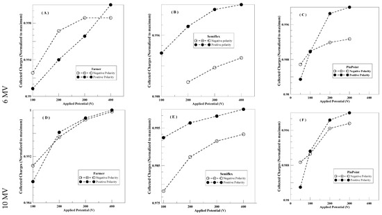
Figure 1.
Response of ion chambers under investigation to the change in polarities over a range of the applied potential, (A) Farmer (6 MV), (B) Semiflex (6 MV), (C) PinPoint (6MV), (D) Farmer (10 MV), (E) Semiflex (10 MV). And (F) PinPoint (10 MV).
For the 6 MV beam, the Farmer ion chamber response in positive polarity was lower than that of negative polarity at the operating potential of 100 V, and then started to increase linearly up to 400 V, while the response in negative polarity increased in a non-linear, saturating pattern up to 400 V, where the response of the positive polarity became greater. For the Semiflex ion chamber, the response in positive polarity, in general, was greater than the corresponding response in negative polarity over the studied range of the applied potential (V). For the PinPoint ion chamber, the positive polarity response was lower in the beginning at 50 V, and then became equal to the negative response at 100 V, and started to dominate for 200 V and 300 V.
For the 10 MV beam, similar behavior was noticed for the ion chambers Semiflex and PinPoint, while for the Farmer ion chamber, there were minor differences between the behavior of both polarities over the studied range of the applied potential, except at the lowest point of 100 V, where the response in negative polarity was greater than that in positive polarity.
In general, it is noticed that for the Semiflex ion chamber, the response of the ion chamber in positive polarity is higher than the response in negative polarity over the range from 100 V to 400 V by a ratio of 0.69% to 1.42%. For the other two chambers, Farmer and PinPoint, the response in negative polarity at low V values is usually greater than that in the corresponding positive polarity and saturates earlier, whereas the response in positive polarity is usually greater at high V values, and this applies for both 6 and 10 MV beams. Additionally, the greater beam energy (10 MV) shows less difference between the response values in both polarities.
Table 2 represents the polarity correction factor (KPol) for the response of the three ion chambers under investigation, evaluated according to Equation (1) and for the two beams (6 MV and 10 MV). Values of the polarity correction factor were evaluated at different values of the applied potential (V), ranging from 100 V to 400 V for farmer and Semiflex ion chambers and from 50 V to 300 V for the PinPoint ion chamber, KPol was evaluated for two cases: the first, where the reference polarity is negative, and the second, where the reference polarity is positive.
Table 2.
Polarity correction factors (KPol) for the chambers under study.
From Table 2, in the case where the reference polarity is negative, the polarity correction factor is very sensitive to the applied potential value and mostly increases as V increases. In contrast to the case of the positive reference polarity, KPol mostly decreases as V increases. Additionally, in the 10 MV beam, similar behavior is noticeable for the two cases; however, the values of KPol are greater than those of the 6 MV beam.
3.2. Saturation Behavior
Figure 2 represents the saturation curves of the ion chambers under study for both radiation beams, 6 MV and 10 MV, evaluated according to Equation (2) and at negative polarities. For the Farmer ion chamber, charges collected per unit time at 50 V are about 97.9% of those collected at the recommended operating potential (400 V). Increments in the applied potential in steps of 50 V led to the non-linear increase in the collected charges until reaching saturation. Semiflex and PinPoint chambers showed similar behavior, where the Semiflex ion chamber response at 50 V was 98.8% of the recommended operating value at 400 V, while the PinPoint chamber response at 50 V was 98.3% with respect to the corresponding value at 300 V (the recommended operating potential).
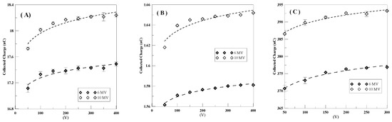
Figure 2.
Saturation curves of the three ion chambers under study, (A) Farmer, (B) Semiflex, and (C) Pinpoint ion chambers over the two beams: 6 MV and 10 MV.
In Figure 2, all response data were fitted using the power fitting according to the formula Ln (Y) = a × Ln (X) + b, where a, b, and the coefficient of determination (R2) for the studied cases are tabulated in Table 3. In general, the response in the 10 MV beam was greater than that of the 6 MV beam for all chambers by a percentage ranging from 3.6% to 4.5%.
Table 3.
Fitting parameters of saturation curves for the chambers under study.
In Table 4, the ion recombination correction factor (Ks) was evaluated for the three ion chambers according to Equation (2). Values of ao, a1, and a2 were implemented according to the corresponding values from the international code of practice, TRS No. 398, issued by the International Atomic Energy Authority (IAEA, TRS No. 398, 2024).
Table 4.
Ion recombination correction factor, Ks at different values of V1 and the corresponding values of collection effeciencies, fv.
Values of V1 varied from 200 V to 400 V for the Farmer and Semiflex chambers and up to 300 V for the PinPoint chamber. V2 was set to obtain a V1/V2 ratio of 2, 2.5, 3, 3.5, 4, and 5. From the table, as a general remark, Ks decreases as V1 increases. Also, cases with higher V1/V2 values have lower Ks values at the same value of V1. It is also worth mentioning that the values of Ks at higher beam energies (10 MV beam) are greater than the corresponding values evaluated at 6 MV beam.
Collection efficiency due to volume recombination can be estimated through Equation (5), where the collection efficiency (fv) is merely the multiplicative inverse of the volume ion recombination correction factor (Ks):
fv = Ks−1
Obtained FV values are tabulated in Table 4, where the maximum efficiencies of the Farmer and Semiflex ion chambers are achieved at 400 V operating potential at V1/V2 = 4, and at 300 V at V1/V2 = 2 for the PinPoint ion chamber for the 6 MV beam, while for the 10 MV beam, the maximum efficiency was achieved at 400 V operating potential at V1/V2 = 2 for both the Farmer and Semiflex ion chambers, and at 300 V at V1/V2 = 3 for the PinPoint ion chamber.
Selection of the V1/V2 ratio is critical in the process of the evaluation of volume ion recombination and hence the collection efficiency; for example, for the Farmer and Semiflex ion chambers, the higher the V1/V2 value, the greater fV at the same operating potential, and this applies for the 6 MV beam and to a lesser extent for the 10 MV beam.
3.3. Beam Quality Index
The beam quality correction factor, KQ,Qo, was evaluated for each ion chamber under study for the two radiation beams, 6 MV and 10 MV, according to the experimental procedures in Section 2.4.3.
Experimentally evaluated TPR20,10 and hence KQ,Qo for the Farmer, Semiflex, and PinPoint chambers are tabulated in Table 5. For the 6 MV beam, TPR20,10 ranges from 0.6864 to 0.6897, while for the 10 MV beam, it ranges from 0.7319 to 0.7361. The corresponding KQ,Qo ranges from 0.9876 to 0.9905 for the 6 MV beam, while it decreases for the 10 MV beam, ranging from 0.9753 to 0.9798.
Table 5.
TPR20,10, beam quality correction factors KQ,Qo, and volume averaging correction factors for three ion chambers in 6 MV and 10 MV beams.
3.4. Volume Averaging Correction Factor
In flattening filter-free (FFF) photon beams, it is crucial to correct for the beam non-uniformity in the vicinity of the ion chamber reference point. KVol, the volume averaging correction factor for the ion chambers under study, is tabulated in Table 5, where it is directly proportional to the chamber volume and specifically to the cavity length; hence, the PinPoint chamber possesses the lowest value of KVol, while the highest values belong to the Farmer ion chamber.
KVol values are similar in both beams for Semiflex and PinPoint ion chambers, while there is a small difference in the case of the Farmer ion chamber, which does not exceed 0.04%.
4. Conclusions
During this study, three ion chambers were characterized, and their performance in terms of several essential related parameters was evaluated. To evaluate the effect of different polarities on the chamber response, the polarity correction factor (KPol) was determined for each ion chamber and for the two beams: 6 MV and 10 MV. KPol depends on the reference polarity used and the applied potential at which measurements were performed, unless otherwise recommended by the manufacturer. Positive polarity is recommended, as it results in better performance in most cases and better readings at the operating polarizing potential.
Also, saturation behaviors of the chambers were studied, where the volume ion recombination correction factor (KS) was evaluated for each chamber, considering a spectrum of the assumed V1 and V2 values for the two beams used. The corresponding collection efficiency values were also evaluated, and it was proved that the values of KS and fVol are dependent on V1/V2; in general, restrictions on the selection of this ratio should be identified in the used codes of practice. Also, fv values were higher in most cases in the 6 MV beam than in the 10 MV beam. The tissue–phantom ratio (TPR20,10) was used as a beam quality index, and KQ,Qo was evaluated for each ion chamber in the two beams: 6 MV and 10 MV. KQ,Qo ranged from 0.9876 to 0.9905 for the 6 MV beam, and for the 10 MV beam, it ranged from 0.9753 to 0.9798.
Also, the volume-averaging correction factor was evaluated and was found to depend on the chamber volume, with very limited impact from the beam quality. It is recommended that these characteristics and tests be considered in international and national codes of practice for reference beam radiation dosimetry.
Author Contributions
Conceptualization, S.A. and A.M.M.; for methodology, Y.H.; for software, A.W.; for validation, A.W., A.M.M. and Y.H.;for formal analysis, A.M.M.; for investigation, S.M.; for resources, Y.H.; for data curation, S.M.; for writing—original draft preparation, A.M.M.; for writing—review and editing, S.M.; for visualization, S.A.; for supervision, Y.H.; and for project administration, A.M.M.; No funding acquisition required. All authors have read and agreed to the published version of the manuscript.
Funding
This research received no external funding.
Data Availability Statement
Data is available upon request.
Conflicts of Interest
The authors declare no conflict of interest.
References
- Maghraby, A.M. Efficiencies of Some Spherical Ion Chambers in Continuous and Pulsed Radiation: A Numerical Evaluation. Pol. J. Radiol. 2015, 80, 515–522. [Google Scholar] [CrossRef][Green Version]
- Boag, J. Ionization Chambers Radiation Dosimetry; Attix, F.H., Roesch, W.C., Eds.; Academic Press: New York, NY, USA, 1966; Volume II. [Google Scholar]
- BIPM. Measuring Conditions Used for the Calibration Of Ionization Chambers at BIPM; Rapport BIPM 04/17; BIPM: Paris, France, 2004. [Google Scholar]
- Prado, J.D.R.; Reynaldo, S.R.; Lacerda, M.A.d.S. Study of the gamma radiation fields of irradiators in a calibration laboratory using Monte Carlo codes. Appl. Radiat. Isot. 2025, 220, 111784. [Google Scholar] [CrossRef]
- Lechner, W.; Palmans, H. Uncertainty estimation for dosimetry in radiation oncology. Phys. Imaging Radiat. Oncol. 2025, 34, 100773. [Google Scholar] [CrossRef] [PubMed]
- Maghraby, A.M.; Shqair, M. A new approach for the evaluation of the effective electrode spacing in spherical ion chambers. Nucl. Instrum. Methods Phys. Res. A 2016, 834, 10–15. [Google Scholar] [CrossRef]
- Abd El-Wahab, H.; Ghobashy, M.M.; Nady, N.; Naser, A.M.; Abdelhai, F.; El-Damhougy, B.K. Radiation synthesis of poly vinylpyrrolidone andpolyacrylamide hydrogels as soil conditioner. Al-Azhar Bull. Sci. 2018, 29, 1–7. [Google Scholar]
- El-Faramawy, N.; Ameen, R.; El-Haddad, K.; Maghraby, A.; El-Zainy, M. Effects of gamma radiation on hard dental tissues of albino rats using scanning electron microscope—Part 1. Radiat. Eff. Defects Solids 2011, 166, 927–934. [Google Scholar] [CrossRef]
- Maghraby, A.; Salama, E.; Mansour, A. EPR/Homotaurine: A possible dosimetry system for high doses. Nucl. Instrum. Methods Phys. Res. A 2011, 659, 504–507. [Google Scholar] [CrossRef]
- Cruz, W.; Narayanasamy, G.; Papanikolaou, N.; Stathakis, S. Dosimetric comparison of water phantoms, ion chambers, and data acquisition modes for LINAC characterization. Radiat. Meas. 2015, 82, 108–114. [Google Scholar] [CrossRef]
- El-Amary, A.; Al Saeed, A.A.; Saleh, S.; Abouelenein, H. Study of the different parameters affecting the quality of radiotherapy treatment planning of breast cancer patients. Int. J. Theor. Appl. Res. 2025, 4, 689–698. [Google Scholar] [CrossRef]
- Eiraba, K.; El Shahat, K.; El Dib, A.; Al Ashkar, M. Modeling of photon and electron beams for monte Carlo simulation based on treatment planning systems. Al-Azhar Bull. Sci. 2013, 24, 29–40. [Google Scholar] [CrossRef]
- Ruiz-García, I.; Moreno-Pérez, J.A.; Valdivieso, P.; Escobedo, P.; Palma, A.J.; Vila, R.; Carvajal, M.A. High dose-rate gamma radiation response of commercial off-the-shelf diodes. Radiat. Phys. Chem. 2025, 238, 113166. [Google Scholar] [CrossRef]
- Bannan, A.; Sekkat, H.; El Mouden, O.; Khallouqi, A.; El Baydaoui, R.; Bougteb, M.; El Rhazouani, O.; Saidi, K.; Elcadi, Z.A.; Mkimel, M. Investigating the performance of the novel microSilicon diode detector for high-resolution dosimetry in radiotherapy: Flat and FFF beams across multiple energies. Nucl. Instrum. Methods Phys. Res. B 2025, 570, 165945. [Google Scholar] [CrossRef]
- Lang, X.; Hu, Z.; Luo, F.; Mao, R.; Li, M.; Zhou, K.; Xu, Z.; Li, J.; Xiao, G. Characterization of real-time dose measurement using monitor ionization chamber in electron beam FLASH radiotherapy. Nucl. Eng. Technol. 2025, 57, 103551. [Google Scholar] [CrossRef]
- Zou, M.; Bohon, J.; Smedley, J.; Kim, J.; Xu, Z.; Ryu, S.; Muller, E.M. Single-crystal diamond detector for flattening-filter-free and small-field dosimetry: Toward transparent beam imaging in clinical radiotherapy. Nucl. Instrum. Methods Phys. Res. A 2025, 1083, 171084. [Google Scholar] [CrossRef]
- Ragab, H.; Abdelaziz, D.M.; Ereiba, K.T.; Abdelgawad, M.H. Advancing dosimetric precision in radiosurgery: HyperArc versus VMAT evaluated through patient-specific QA with point dose, PDIP, and OCTAVIUS 4D SRS. Radiat. Phys. Chem. 2025, 240, 113384. [Google Scholar] [CrossRef]
- Inan, G.; Gul, O.V. Evaluation of dosimetric characteristics in small field electron beam parameters using different dosimeters. Radiat. Phys. Chem. 2025, 240, 113438. [Google Scholar] [CrossRef]
- Chand, B.; Kumar, M.; Kumar, M.; Priyamvda. Comprehensive review of small field dosimetry. Eur. J. Mol. Clin. Med. 2020, 7, 3595–3607. [Google Scholar]
- Moradi, F.; Sani, S.A.; Norazri, M.H.; Ung, N.M.; Almugren, K.S.; Saraee, K.R.E.; Bradley, D.A. Evaluation of perturbation effects for various size TLDs in small field dosimetry. Radiat. Phys. Chem. 2022, 200, 110256. [Google Scholar] [CrossRef]
- IAEA. Absorbed Dose Determination in External Beam Radiotherapy: An International Code of Practice for Dosimetry Based on Standards of Absorbed Dose to Water; IAEA Technical Reports Series No. 398, Rev.1, (TRS 398); IAEA: Vienna, Austria, 2024. [Google Scholar]
- Almond, P.R.; Biggs, P.J.; Coursey, B.M.; Hanson, W.F.; Huq, M.S.; Nath, R.; Rogers, D.W.O. AAPM’s TG-51 protocol for clinical reference dosimetry of high-energy photon and electron beams. Med. Phys. 1999, 26, 1847–1870. [Google Scholar] [CrossRef]
- IAEA. Dosimetry of Small Static Fields Used in External Beam Radiotherapy; IAEA Technical Reports Series No. 483, (TRS 483); IAEA: Vienna, Austria, 2017. [Google Scholar]
- Nisbety, A.; Thwaites, D.I. Polarity and ion recombination correction factors for ionization chambers employed in electron beam dosimetry. Phys. Med. Biol. 1998, 43, 435–443. [Google Scholar] [CrossRef]
- Low, D.A.; Parikh, P.; Dempsey, J.F.; Wahab, S.; Huq, S. Ionization chamber volume averaging effects in dynamic intensity modulated radiation therapy beams. Med. Phys. 2003, 30, 1706–1711. [Google Scholar] [CrossRef] [PubMed]


Disclaimer/Publisher’s Note: The statements, opinions and data contained in all publications are solely those of the individual author(s) and contributor(s) and not of MDPI and/or the editor(s). MDPI and/or the editor(s) disclaim responsibility for any injury to people or property resulting from any ideas, methods, instructions or products referred to in the content. |
© 2026 by the authors. Licensee MDPI, Basel, Switzerland. This article is an open access article distributed under the terms and conditions of the Creative Commons Attribution (CC BY) license.