


Abstract
This work introduces the design, analysis, and validation of a highly compact dual-band bandpass filter (BPF) and power divider (PD) employing half-mode substrate-integrated rectangular waveguide (HMSIRW) technology. To achieve sub-cutoff evanescent-mode operation, an octagonal split-loop resonator (OSLR) integrated with a pair of symmetric folded split rectangular arms (SRAs) is patterned onto the upper metallic layer of the cavity. This resonator interaction establishes two distinct passbands at 2.03 GHz and 7.5 GHz while significantly reducing circuit footprint and insertion loss. The operational principle, equivalent-circuit model, and parametric analysis are discussed in detailed. The fabricated prototypes of the dual-band BPF and PD occupy an ultra-compact size of 0.0064λg2 (which is more compact compared to existing HMSIRW PDs). The prototypes demonstrate an insertion loss smaller than 0.84 dB, along with a high return loss below −15.2 dB, and a 3 dB fractional bandwidth exceeding 21.6% across both bands. A transmission zero is obtained at 3.6 GHz with an attenuation level of −36 dB. Measured results align with the simulated responses, making the proposed designs suitable for multi-band RF front-end modules, in addition to L/S/C-band and 6G applications.
1. Introduction
The enhancement of emerging wireless communication networks has increasing requirements for compact, cost-effective, and high-performing microwave components that offer multifunctional operation within a single structure. Power dividers (PDs) and bandpass filters (BPFs) are the key elements of RF front-end circuits, which serve a vital role in signal distribution and spectral filtering. Filtering power dividers (FPDs) emerge as a highly effective solution owing to their ability to combine signal filtering and power division within a single device. Various techniques for designing HMSIW dual-band filters are documented in [1,2,3,4,5,6,7,8,9,10,11,12,13]. In [1], a dual-band HMSIW BPF was developed by using quasi-TEM and TE102 resonant modes; in this slot-line perturbation, it tunes the higher-order mode, and source–load coupling enhances the frequency selectivity. A compact dual-frequency BPF with passbands at 2.4 GHz and 5.2 GHz used for dual-band WLAN applications is proposed in [2]. It is designed with a one-patch resonator, with two groups of loaded stubs employed to control the operating bands. In [3], a resonator section with inverter coupling is introduced to implement a dual- and triple-passband SIW filter. Using the low-pass prototype, both Chebyshev-type and quasi-elliptic filtering responses are obtained, and the structures are realized over the K-band via planar microwave integration. In [4], a dual-frequency bandpass filter exhibiting multiple transmission zeros introduced through source–load coupling and cross-coupling is realized using an over-mode HMSIW resonator, where independent control of each passband is achieved using perturbation slots. A dual-band HMSIW bandpass filter with inner coupling slot-lines and metal holes to tune the operating band employing TE100- and TE103-mode resonant modes is designed in [5]. In [6] single- and dual-band HMSIW BPFs were realized by integrating complementary split-ring resonators (CSRRs) onto HMSIW resonators; this enabled filter operation below the cutoff frequency. Direct microstrip-to-HMSIW feeding eliminated the need for a transition structure, thereby simplifying the overall design. A single compact structure functioning as a filtering power divider (FPD) that integrates filtering and power division functions is proposed in [7]. Quarter-mode SIWs were employed to reduce the overall circuit area, and even-and-odd mode analysis was carried out to analyze the FPD. In [8], a mixed SIW cavity topology was utilized to achieve compact wide-stopband and dual-band filter characteristics. In order to improve isolation and cross-transmission, degenerate orthogonal modes were employed. In [9], a dual-band BPF with a widely separated passband was realized using dual-mode HMSIW rectangular cavities; the unloaded quality factor of HMSIRC was investigated to improve filter performance. The developed structures are suitable for Tx/Rx satellite communication systems. In [10], a dual-band HMSIW BPF was developed by integrating a split-ring resonator, a T-shaped slot, and a defeated ground structure. A metallic ridge embedded inside the HMSIW cavity was introduced to improve bandwidth, demonstrating the suitability of the filter for X- and Ku-band satellite communication applications. In [11], a compact SIW dual-band bandpass filter with closely spaced passbands and independently controllable bandwidths was proposed using mixed-mode cavities (MMCs), where feeding-port offsets regulate the external quality factors. A miniaturized, self-packaged dual-band filter based on SIW MMCs was presented in [12], exploiting the TEM100 and FTE101 modes to establish two passbands. In [13], a compact, fully shielded dual-band BPF was developed using a hybrid SIW–stripline topology incorporating quarter-wavelength stripline resonators.
Several single- and dual-band power dividers have been reported in [14,15,16,17,18,19,20,21,22,23,24,25,26,27,28,29,30,31,32,33,34,35,36,37,38,39,40,41,42] using various techniques. Evanescent-mode techniques (EMTs) have been used to achieve compact size and operation frequency below the conventional waveguide cutoff frequency. In [14], EMT along with dual-band metamaterial loading (ML) on an HMSIW structure was used to realize two passbands below the cutoff frequency. The dual-band response was achieved using metamaterial cells; the dimensional variation of these cells enabled control of the passband center frequencies. In [15], a dual-band HMSIW filter and filtering power divider (FPD) based on EMT and ML is proposed. A reduced-size metamaterial unit cell with dual-negative permittivity is introduced by integrating two distinct types of metamaterials and meander and fractal techniques. In [16], a compact four-way SIW PD and two-way HMSIW PD loaded with complementary split-ring resonators (CSRRs) based on EMT are demonstrated. In [17], COCSRR metamaterial unit cells are introduced by combining CSRR and open CSRR (OCSRR), to realize super-compact dual-band and SIW FPD through EMT. Experimental findings showed that they are suitable for WiMAX and WLAN applications.
CSRRs are used widely to reduce the size of the component by altering the propagation properties of SIW structures. In [18], an SIW power divider loaded with double-circular CSRRs is fabricated, where an additional passband is introduced below the cutoff frequency, which gives a dual-band operation. Multiple resonant modes within an SIW structure can also be obtained by loading an asymmetric CSRR. In [19], an asymmetric double-ring CSRR is incorporated, which gives mixed electric and magnetic coupling at two distinct resonating frequencies, achieving a dual-band operation. In [20], the HMSIW with inner modified circular CSRRs combines the effect of resonator loading and evanescent mode operation, which enables dual-band operation below the HMSIW cutoff frequency and gives multiple transmission zeros, significantly increasing the filtering response and isolation of the output. In [21], a compact filtering power divider was designed using a metamaterial-based CSRR structure coupled with an interdigital capacitor. The zeroth-order resonance (ZOR) offers a substantial degree of miniaturization in the circuit. CSRR-loaded structures allow for compact multi-band operation while enabling flexible control over the operating frequencies and bandwidths by incorporating additional resonant modes within a single SIW cavity. A single SIW cavity filled with perturbed modes with CSRR-induced resonances acted as the framework for the power divider design in [22], which produced adjustable dual-band functioning.
In FPD designs, shielded SIW resonant cavities can substantially increase filtering selectivity, quality factor, and compactness. In [23], even-and-odd mode analysis is performed of dual-band SIW FPD implemented on a single layer using three SIW cavities, and an open stub-loaded square-loop resonator is observed. For 5G millimeter-wave operation, an SIW-based dual-band filtering power divider operating at 28 and 39 GHz is adopted in [24]; PDs below the K-band are the primary utility of the SIW structure. In [25], two passbands could be generated within a single cavity by exploiting the lowest two resonant modes of the triangular SIW cavity. The PD operates at 5.5 and 8.3 GHz with equal absolute bandwidth of 0.8 GHz, and two 50 Ω transmission-line sections loaded with two resisters were incorporated to enhance isolation compared to 20 dB. In [26], a compact dual-band SIW power divider is implemented using slot loading on the ground plane; the slot acts as an electric dipole where variation in these dimensions varies the operating frequency. In [27], a broadband FPD based on an HMSIW structure which is employed as a J-inverter for realizing the filtering response is reported. In [28], single- and dual-band PDs are realized by integrating bandpass filters. By integrating multimode SIR resonators and slot-line isolation technology, a compact wideband HMSIW FPD is designed in [29] to improve and enhance the selectivity and isolation properties.
In [30], a 3 dB equal PD based on corrugated SIW using full-mode to half-mode conversion is proposed with wideband operation and improved output isolation. In [31], PD with a configurable power-splitting ratio employing shielded HMSIW and quarter-mode SIW is designed, and a cross-coupling mechanism reduces the footprint. In [32], four-way equal and unequal and eight-way equal division power dividers are presented; here, a quarter-wavelength-long wedge-shaped SIW structure is used for the power division. In [33], HMSIW Y-junctions arranged in horizontal and vertical orientations are incorporated to design a multilayer four-port out-of-phase power divider realized through 3-D SIW mode coupling, which gives amplitude balance over the X-band. In [34], a compact radial-cavity C-band SIW power divider with eight output ports is developed using an equivalent-circuit model to examine the multiport structure. In [35], a compact HMSIW power divider offering an adjustable power-division ratio is presented. Three prototypes providing power-spitting ratios of 1:1, 1:4, and 1:8 are simulated and fabricated. A mixed-mode magic-T structure is introduced in [36] for balanced FPD applications. Asymmetric shorted stub-loaded resonators are integrated to obtain a dual-band filtering response. To overcome the bandwidth limitations of conventional SIW, a broadband magic-T based on a strip-line embedded hybrid SIW structure is proposed in [37]. The applied signal is equally split into two equal amplitudes due to vertical symmetry. A reconfigurable dual-band power divider for WLAN applications, realized by combining dual-band quadrature hybrids with dual-band phase-shifting networks, is reported in [38]. A Gysel-type PD based on an HMSIW ring is proposed in [39]; the balanced configuration is developed from its single-end counterpart. The six-port structure is combined into three differential pairs, with a 35 Ω microstrip quarter-wavelength line used as the matched load to obtain good isolation. In [40], outputs of the PD of a quasi-lumped coupler and two varactor diodes are used to excite two antennas arranged by a back-to-back configuration. In [41], an HMSIW is integrated with power splitters and composite right/left-handed transmission lines (CRLH-TLs) and is compared with a conventional SIW PD. In [42], a dual-band microstrip Gysel power divider employing two Schiffman phase shifters with π-shaped transmission lines is proposed. Although many techniques are reported for designing SIW/HMSIW filters and power dividers, research is ongoing to find alternate resonator topologies that can attain greater frequency selectivity, enhanced miniaturization, and flexible dual-band features.
This work introduces a highly miniaturized dual-band bandpass filter (BPF) and power divider (PD) implemented using a half-mode substrate-integrated rectangular waveguide (HMSIRW) cavity. The core resonator consists of an octagonal split-loop resonator (OSLR) integrated with a pair of symmetrical folded split rectangular arms (SRAs). The resonant characteristics are associated with the TE10 mode; operating in the evanescent mode, the proposed topology lowers the fundamental cutoff frequency with controlled inter-resonator coupling. The major features of the designed BPF and PD are summarized as follows:
- (a)
- An ultra-compact footprint of 0.0064λg2 is obtained, making it significantly more compact than previously reported HMSIW-based designs.
- (b)
- They achieve a low insertion loss below 0.84 dB along with a return loss greater than −15.2 dB for both the operating bands.
- (c)
- They offer a fractional bandwidth above 29% and 21.6% operating at dual passbands centered at 2.03 GHz and 7.5 GHz, respectively.
- (d)
- A dual-band bandpass filter, along with its extended power divider integration, is successfully presented and analyzed in detail. Version functionalities are presented, experimentally validated, and discussed in detail.
2. Design Analysis of Dual-Band HMSIRW Filter
2.1. Configuration of Dual-Band Filter
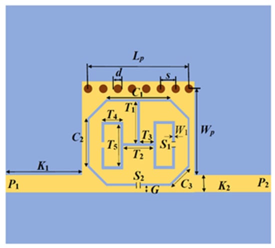
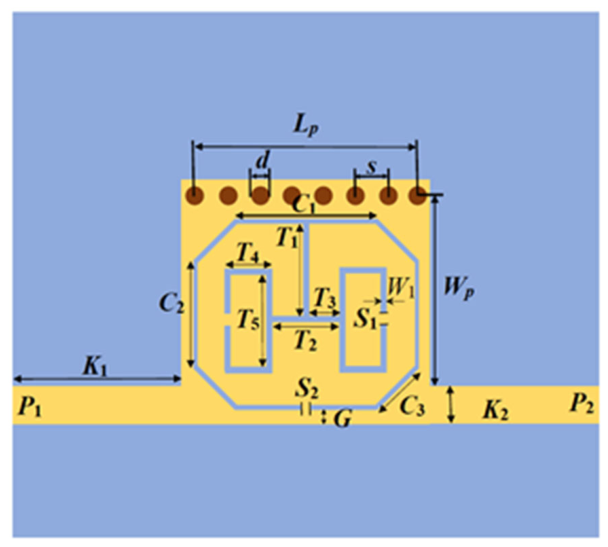
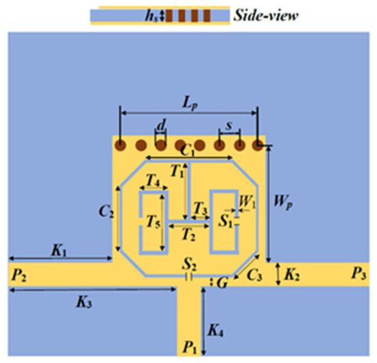
The configuration of the proposed HMSIRW dual-band bandpass filter is illustrated in Figure 1. The filter is realized using an HMSIRW cavity with a row of metallic vias positioned along the upper side to ensure electromagnetic confinement and minimize leakage from the waveguide region. To achieve dual-band operation, an octagonal split-ring resonator embedded with a pair of folded split rectangular arms is symmetrically positioned and etched out on the top layer of the HMSIRW cavity. Excitation is provided via microstrip input and output ports denoted by P1 and P2. The filter is implemented on a low-loss Rogers RT/Duroid 5880 dielectric substrate with a thickness of 0.508 mm, a relative permittivity of 2.2, and a loss tangent of 0.0009. The structural parameters of the proposed dual-band filter is listed in Table 1.
Figure 1.
Schematic of the designed dual-band bandpass filter.
Table 1.
Structural parameters of the proposed dual-band filter.
2.2. Design Evolution
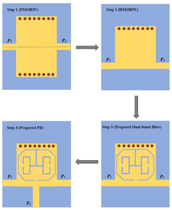
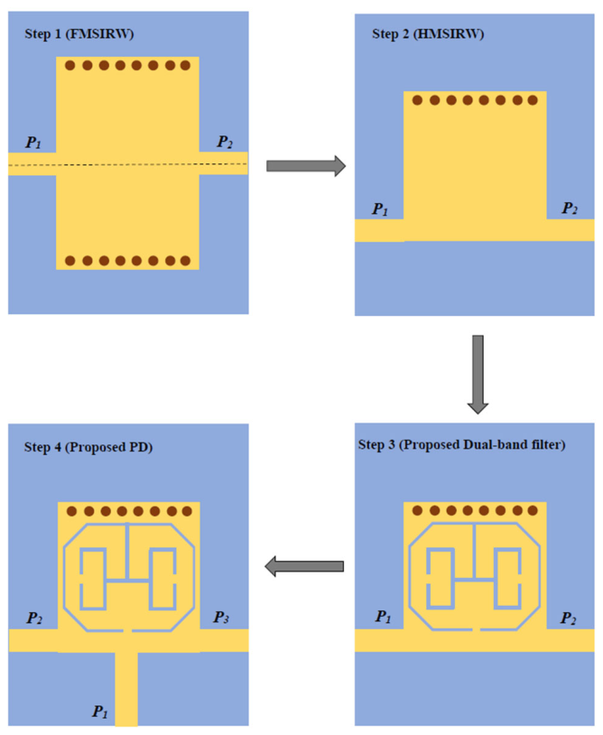
The step-by-step design evolution of the proposed filter and power divider is depicted in Figure 2.
Figure 2.
Evolution steps for designing dual-band BPF and PD.
Step 1: The proposed configuration is developed from a full-mode substrate-integrated rectangular waveguide (FMSIW) formed with two rows of conductive vias of diameter d and center-to-center spacing of s that function as virtual electric walls to confine the electromagnetic fields. The FMSIRW is based on dominant TE10-mode propagation. The effective width of the SIW can be calculated using the formula
Here, Weff and WSIW represent the effective and actual width of the SIW cavity, respectively. The cutoff frequency corresponding to the dominant mode is given by
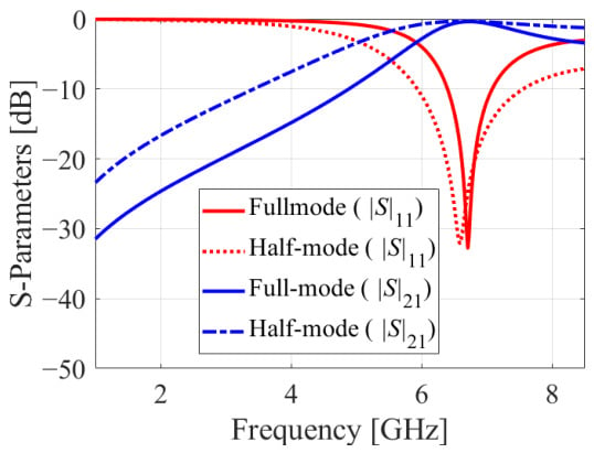
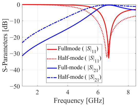
Here, c corresponds to the speed of light, while ϵr denotes the relative permittivity of the dielectric substrate. To ensure the proper electromagnetic confinement inside the cavity, the via spacing is selected according to the expression s ≥ 2d. The EM simulation of traditional FMSIRW and HMSIRW operating in TE10 mode is examined in order to comprehend the size reduction accomplished by the HMSIRW cavity, as shown in Figure 3. The frequency response of the HMSIRW cavity is identical to that of the FMSIRW cavity; however, using HMSIRW reduces the cavity’s size by 50%. As a result, an extremely compact bandpass filter is achieved by using HMSIRW.
Figure 3.
EM-simulated S-parameters of FMSIRW and HMSIRW cavities.
Step 2: The FMSIRW is divided along the magnetic symmetry plane of the TE10 mode to obtain the half-mode substrate-integrated rectangular waveguide (HMSIRW). This reduces the footprint of the structure while retaining the mode of operation.
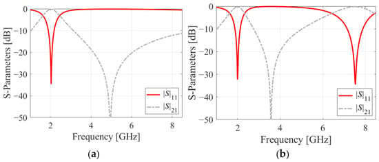
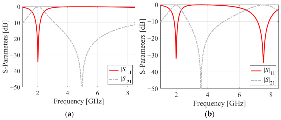
Step 3: The octagonal split-ring resonator embedded with a pair of symmetric compact folded split rectangular arms (SRAs) is positioned symmetrically about the central axis on the HMSIRW cavity and etched out on its surface. This introduces an additional electrical path which is responsible for obtaining dual-band operation. When the HWSIRW cavity is exclusively loaded with an octagonal split-ring resonator, a single-band operation is possible, as shown in Figure 4a. As seen in the figure, the resonance frequency of the fundamental mode is moved from 6.9 GHz to 2 GHz, which provides us the benefit of obtaining size reduction. As shown in Figure 4b, a dual band is produced by loading an octagonal split-ring that is embedded with two symmetric compact folded split rectangular arms (SRAs).
Figure 4.
EM-simulated S-parameters of the suggested filter printed with (a) octagonal split-ring resonator only; (b) octagonal split-ring embedded with a pair of symmetric compact folded split rectangular arms (SRAs).
The input signal is applied through Port 1 (P1) and transferred to the output through Port 2 (P2).
Step 4: The two-port filter design is subsequently extended to a three-port dual-band power divider (PD). Here, P1 serves as the excitation port, while P2 and P3 function as the two output ports, providing an equal power split between the output branches.
2.3. Electric-Field Analysis
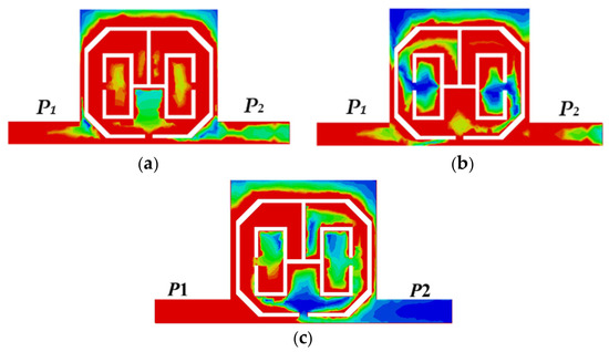
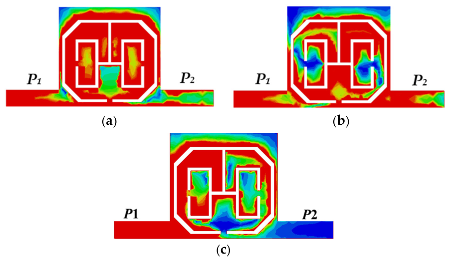
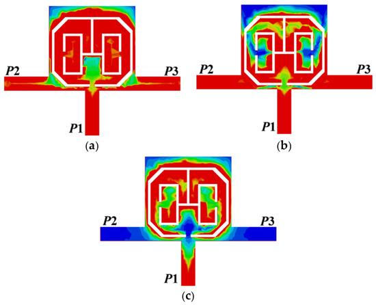
The electric-field characteristics of the developed dual-band BPF are depicted in Figure 5. From the simulated plot Figure 5a, it can be seen that at the first resonating frequency of 2.03 GHz, the E-field is mainly concentrated in the central coupling region between the two inner folded rectangular sections. This confinement indicates a strong coupling between the feed and the resonating element. There is comparatively lower field intensity along the peripheral portion of the octagonal split-ring. There is a symmetric distribution of the E-field about the central axis along the two sides of the structures; this reflects balanced excitation.
Figure 5.
Electric field distribution of dual-band HMSIW filter at (a) 2.03 GHz; (b) 7.5 GHz; (c) 3.6 GHz.
Figure 5b illustrates the electric field distribution at the second resonating band: 7.5 GHz. From the field distribution, it is observed that the E-field is intense around the inner folded arms on both the sides of the resonator, indicating enhanced capacitive loading. When compared with the first operating band, the field distribution is less concentrated at the central region; this demonstrates the field configuration in the upper band. The electric-field distribution at 3.6 GHz is shown in Figure 5c, corresponding to the location of transmission zero of the proposed filter. From the field distribution, it is observed that the E-field is mainly concentrated around the inner folded rectangular arms and the central coupling region, with almost no significant field intensity along the output feed. This indicates that at this frequency, electromagnetic energy transfer from the input port to the output ports is suppressed.
2.4. Equivalent-Circuit Model
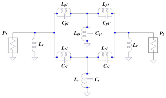
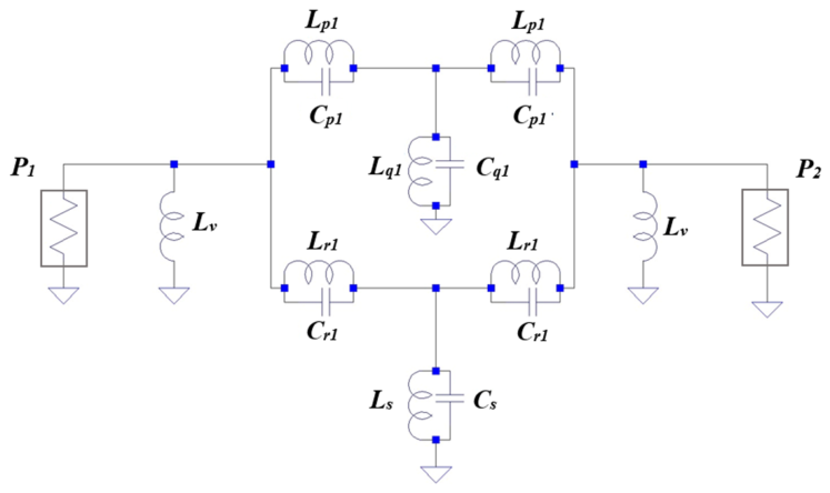
To model the electromagnetic characteristics of the proposed dual-band HMSIRW filter, a lumped-element LC circuit network is constructed as shown in Figure 6. This representation provides an interpretation of the coupling mechanism and resonant paths responsible for the two operating bands. In this circuit representation, the shunt inductors (Lv) connected to P1 and P2 characterize the inductive effect of the metallic vias connecting the conducting region to the ground plane. The dual-path symmetrical topology captures both the upper and lower slot perturbations of the octagonal resonator structure. The central portion of the circuit contains two symmetrical resonant paths. The upper signal path employs parallel LC tanks (Lp1, Cp1) connected in series to model the combined inductive and capacitive coupling along the upper boundary of the octagonal structure. This upper signal path is connected to a grounded shunt LC tank (Lq1, Cq1); this represents the primary resonant mode of the top resonating section. Similarly, the lower signal path consists of a series-connected parallel LC tank (Lr1, Cr1) coupled to a shunt LC tank (Ls, Cs), representing the lower slotted region and folded rectangular arms responsible for the second resonant mode. The electrical coefficients of the equivalent-circuit model are summarized in Table 2.
Figure 6.
Circuit-level representation of proposed HMSIW dual-band filter.
Table 2.
Electrical coefficients of the equivalent model.
The inductive components originate from the magnetic field distribution along with the conducting traces, whereas the capacitive elements account for E-field concentration within the etched out slots and split gaps. The fundamental resonant frequency for an individual LC tank can be calculated from its equivalent inductance and capacitance using
The interaction of these elements with the main signal path affects the coupling strength, attenuation characteristics, and resonance characteristics of the filter. Any changes in the physical dimensions of the proposed filter alter these equivalent parameters and consequently shift the resonant frequencies.
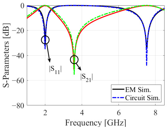
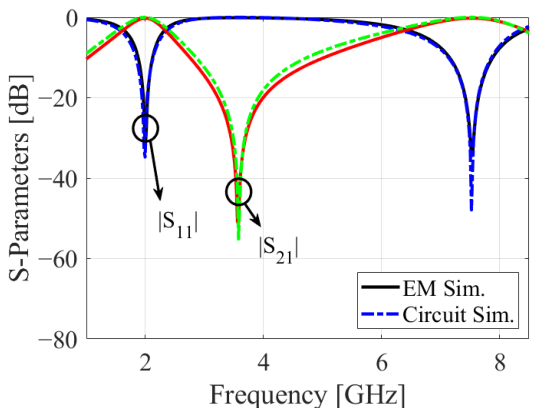
The circuit full-wave simulated frequency responses of the proposed dual-band BPF are illustrated in Figure 7. As seen in the circuit simulation, the filter exhibits two distinct passbands positioned at approximately 2.03 GHz and 7.5 GHz, with the transmission coefficient |S21| approaching 0 dB in both passbands, indicating efficient signal transmission. At the corresponding resonant frequencies, |S11| reaches approximately −35 dB and −48 dB, respectively, indicating strong input impedance matching and minimal reflected power. A sharp transmission zero is observed around 3.6 GHz, with an attenuation level exceeding 50 dB, thereby providing high inter-band isolation and effective suppression of unwanted signals. The overall response characteristics remain consistent in both the EM and circuit simulations, with close agreement observed across the frequency range, thereby validating the proposed circuit model.
Figure 7.
Circuit- and EM-simulated S-parameters of dual-band HMSIRW filter.
2.5. Parametric Variation
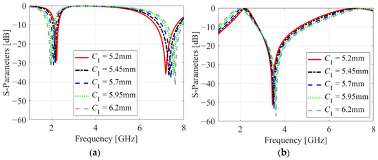
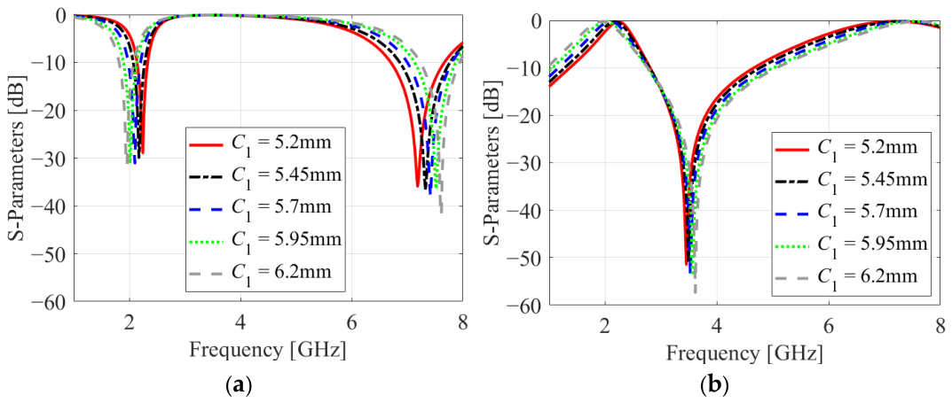
The influence of C1 on the simulated S-parameters is illustrated in Figure 8. As C1 varies from 5.2 mm to 6.2 mm, the lower and upper operating bands are tuned from 1.95 GHz to 2.25 GHz and 7.2 GHz to 7.61 GHz, respectively. It can also be observed that the location of transmission zero is shifted from 3.45 GHz to 3.61 GHz. This indicates that C1 effectively controls the position and attenuation characteristics of the transmission zero.
Figure 8.
Variation in simulated frequency responses as function of C1. (a) Reflection coefficients; (b) Transmission coefficients.
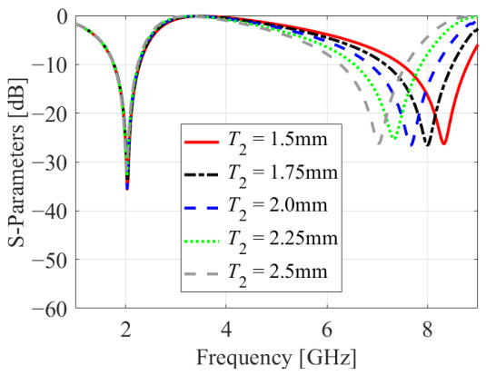
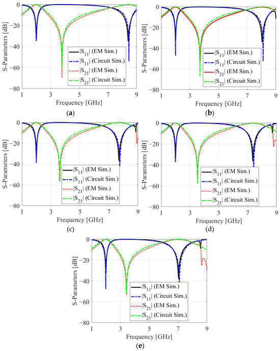
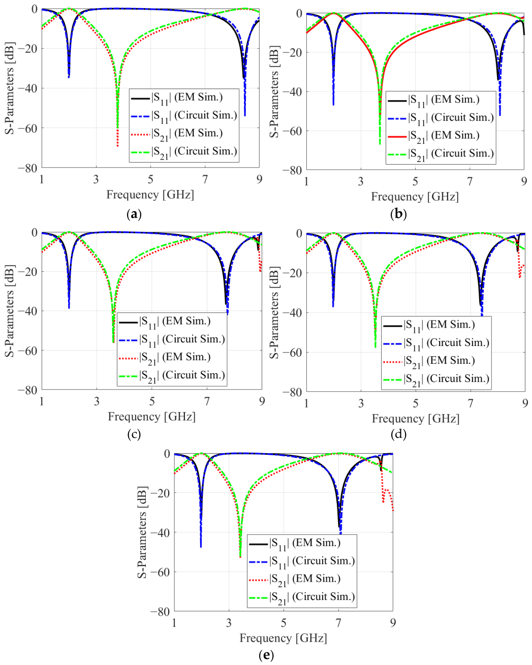
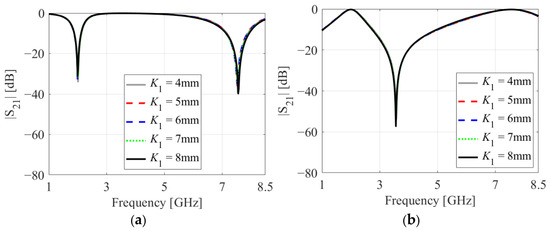
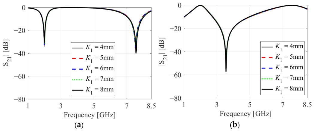
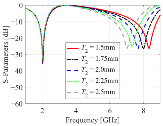
Figure 9 presents the parametric analysis of the proposed structure for varying T2 from 1.5 mm to 2.5 mm. The first resonant band remains intact around 2 GHz; this indicates that the lower operating band is insensitive to variations in T2. The second resonant band exhibits a significant shift toward lower frequencies, moving from approximately 8.4 GHz to 7 GHz as T2 increases. Hence, T2 serves as an effective tuning parameter for controlling the upper resonant frequency. The practical applicability of the suggested dual-band filter by varying the design parameters is shown in Table 3. From the table, it can be observed that both the frequency bands can be tuned by varying the parameter C1. Also, it is noted that the lower band can be fixed while the upper band can be tuned by varying the parameter T2. Given these tuning ranges, the proposed dual-band filter can be employed for the L-band, S-band, C-band and next-generation 6G applications. A parametric study with respect to the variable T2 is analyzed and mapped with equivalent-circuit model results as shown in Figure 10. The physical dimension (T2) and its equivalent electrical parameters (Cq1 and Lr1) are listed in Table 4 for Figure 10a–e. It can be noted that when T2 varied, the S-parameters changed, which can be modeled using the electrical parameters Cq1 and Lr1 without altering any other electrical parameters. Figure 11 shows the reflection and transmission coefficient variation with respect to the length of the feedline (K1). The length of the feedline has negligible effect on the filter’s frequency response, as seen in the figure.
Figure 9.
Simulated |S11| response by varying T2.
Table 3.
Practicality of the proposed dual-band filter.
Figure 10.
S-parameters of the dual-band filter due to variation in T2. (a) T2 = 1.5 mm; (b) T2 = 1.75 mm; (c) T2 = 2.0 mm; (d) T2 = 2.25 mm; (e) T2 = 2.5 mm.
Table 4.
Physical and electrical parameters for parametric analysis.
Figure 11.
Variation in simulated frequency responses as function of K1. (a) Reflection coefficients; (b) Transmission coefficients.
2.6. Loss Calculation and Comparative Analysis
The total loss of the proposed filter is evaluated using the equation
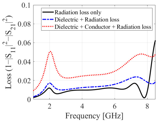
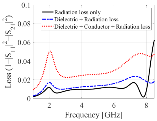
Here, |S11| and |S21| represent the refection coefficient and transmission coefficient, respectively. Overall analysis of loss can be performed by referring to Figure 12. To quantify the contribution of individual loss mechanisms, three simulation conditions are considered: radiation loss only; dielectric and radiation losses; and dielectric, conductor, and radiation losses. The total power attenuation consists of dielectric loss originating from the substrate between the conducting layers between the ground and patch, radiation loss from the metallic via boundary, and conductor loss across the metallic surfaces. At the lower operating band near 2.0 GHz, the radiation loss is minimal at approximately 0.01, confirming strong electromagnetic energy confinement within the resonant cavity. As the frequency increases toward the second operating region, a progressive rise in loss is observed, followed by a sharp escalation above 8 GHz due to higher-order mode excitation and radiation leakage beyond the operational passbands.
Figure 12.
Loss analysis of the proposed dual-band filter.
When dielectric loss is incorporated along with radiation loss, a noticeable increase in overall loss is observed across both operating regions. At approximately 2 GHz, the loss increases to nearly 0.017, while around 7–7.5 GHz, it reaches approximately 0.024. This increase is associated with dielectric dissipation in regions of high electric-field concentration.
3. Development of Dual-Band PD
3.1. Schematic of PD
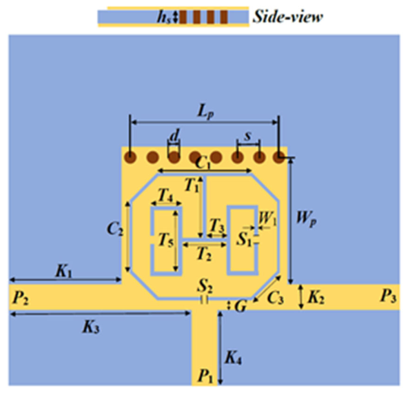
The delineated dual-band bandpass filter is further extended to realize an equal power divider (PD) while retaining the original resonating configuration. As depicted in Figure 13, the structure is converted into a three-port network featuring a single input port (P1) and two symmetrical output ports (P2 and P3). Signal energy injected at P1 excites the central resonant cavity, where the mirror-image geometry of the output channels directs equal power to both P2 and P3, resulting in a balanced 3 dB split with matching amplitude and phase characteristics across both operating passbands. Because the internal dimensions of the HMSIW resonating cavity are kept identical to the original filter design, the fundamental dual-band frequency response is fully preserved. This monolithic integration combines frequency selection and power division into a single physical layout, avoiding the extra circuit footprint, impedance-matching networks, and interconnection losses typical of conventional cascaded filter–divider systems.
Figure 13.
Schematic of the suggested dual-band power divider.
3.2. Electric-Field Analysis
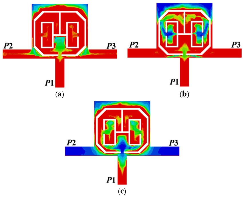
E-field distribution at 2.03 GHz is shown in Figure 14a. The electric field is concentrated around the central coupling region and the inner attached folded split rectangular arms. This distribution pattern indicates the resonance mechanism at the fundamental frequency. The electric field near the feed junction indicates efficient electromagnetic coupling between the input port and the resonator. The balanced energy distribution enhances the electromagnetic coupling with minimum field leakage.
Figure 14.
Simulated electric-field profiles of the proposed equal power divider illustrating field confinement and excitation behavior at (a) 2.03 GHz, (b) 7.5 GHz, and (c) 3.34 GHz.
Electric-field distribution at 7.5 GHz is shown in Figure 14b. The E-field is redistributed from the central region towards the outer octagonal split-ring resonator (OSRR) and also extends towards the inner embedded rectangular arms. The strong field concentration around the outer octagonal ring is mainly due to the coupling between OSRR and SRAs; this excitation indicates the excitation of higher-order resonant modes. The E-field is symmetrically distributed on both halves, confirming balanced and equal power division at the second passband. Figure 14c depicts the electric-field distribution at 3.34 GHz, corresponding to the location transmission zero of the proposed power divider. From the field distribution, it is observed that the E-field is mainly concentrated around the central input-feed junction and the coupling region of the resonator, with almost no noticeable field intensity along the output feed. This shows that electromagnetic energy transmission at this frequency is suppressed from the input port to the output ports.
3.3. Parametric Variation
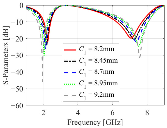
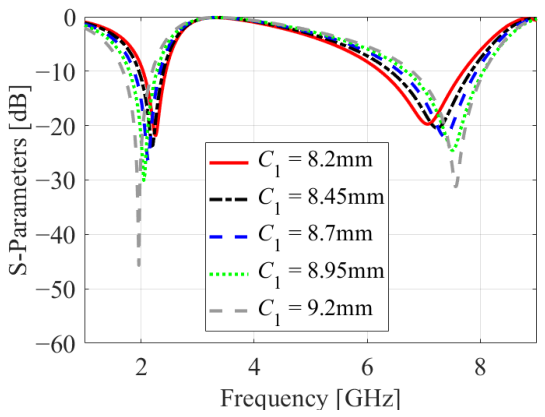
Figure 15 presents the parametric analysis of the proposed HWSIW FPD with the variation of C1 from 8.2 mm to 9.2 mm. From the figure, it can be observed that upon increasing C1, the first operating band shifts slightly towards the lower frequency. Correspondingly, the return-loss dip deepens from approximately −22 dB to –45 dB; this indicates improved impedance matching. Simultaneously, the second operating band shifts towards a higher frequency, and the resonant dip deepens to −30 dB. Together it can be concluded that C1 effectively controls the operation of the passbands along with improving return-loss characteristics.
Figure 15.
Parametric analysis of the simulated S11 response with varying C1.
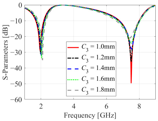
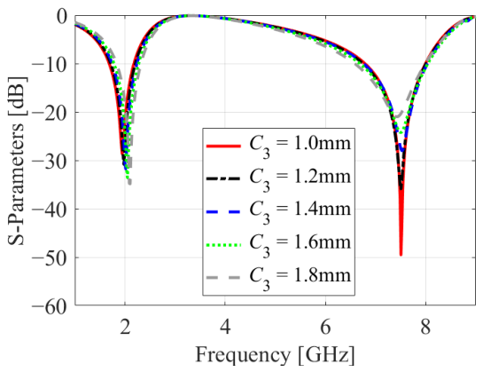
The effect of varying C3 from 1 mm to 1.8 mm on the S-parameter of the designed FPD is represented in Figure 16. It can be noted that increasing C3 shifts the resonating frequency slightly towards the right side at the lower operating frequency. In the upper resonating band, there is a negligible shift but the resonance notch becomes shorter as C3 increases, from approximately −50 dB to −20 dB. This indicates deterioration in impedance matching. Therefore, C3 is important for achieving proper impedance matching, particularly at the higher-frequency band.
Figure 16.
Influence of C3 on the simulated input reflection characteristics.
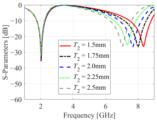
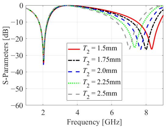
Figure 17 illustrates the effect of varying the parameter T2 on the S-parameter response. It can be observed from the figure that on varying T2 from 1.5 mm to 2.5 mm the resonant frequencies and resonance notch at 2.03 GHz remain unchanged. Meanwhile, in the upper passband the frequencies significantly shift towards lower values as T2 increases. Therefore, variation of T2 helps in tuning the upper passband with a negligible impact on the lower passband. It is an effective design parameter for controlling the frequency independently at the higher passband.
Figure 17.
Effect of T2 variation on the simulated |S11| response.
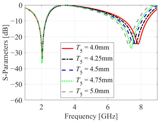
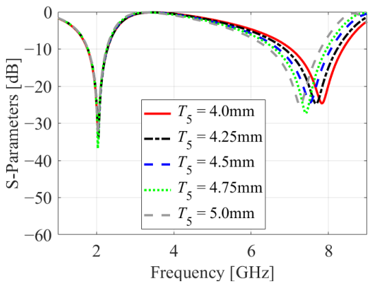
Figure 18 illustrates the parametric analysis of the proposed structure for T5 varied from 4.0 mm to 5.0 mm. The lower resonant frequency remains nearly unchanged around 2 GHz, indicating that this parameter has minimal influence on the lower operating band, whereas the upper resonant frequency exhibits a noticeable shift with variation in T5, confirming its influence on the higher-frequency response. Hence, T5 can be used as an effective tuning parameter for controlling the upper resonant frequency while maintaining the lower operating band.
Figure 18.
Effect of T5 variation on the simulated |S11| response.
4. Prototype Fabrication and Experimental Results
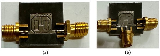
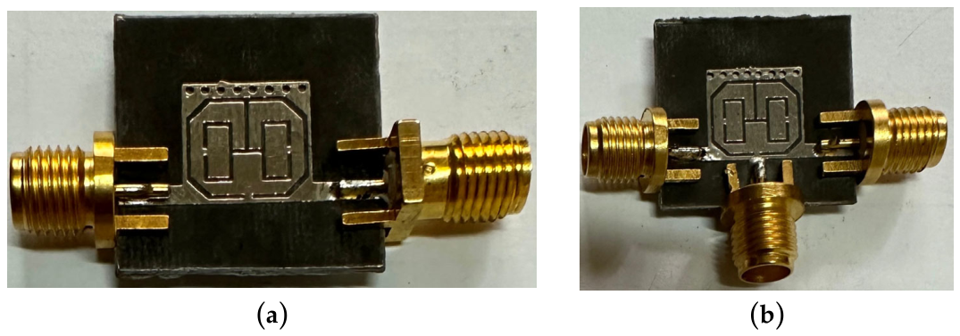
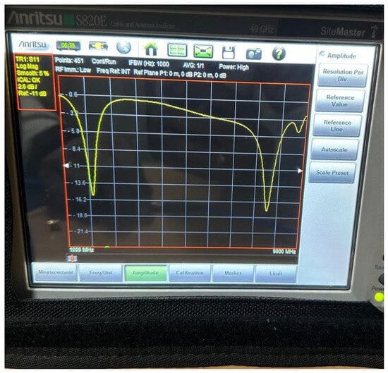
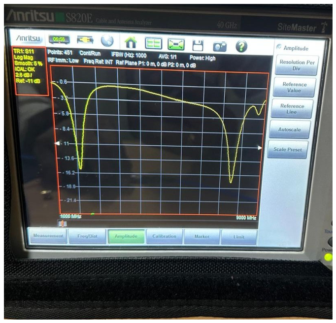
To experimentally verify the proposed design methodology, the developed HMSIRW bandpass filter and power divider are fabricated and measured using a vector network analyzer. The two prototypes are implemented on Rogers RT/Duroid 5880 dielectric material, with a substrate thickness of 0.508 mm, relative permittivity of 2.2, and loss tangent of 0.0009. Figure 19 depicts photographs of the fabricated BPF and power divider prototypes. The experimentally recorded results exhibit close correspondence with the corresponding full-wave electromagnetic (EM) simulations, confirming the performance of the proposed design approach. A small variation is noticed between the simulated and measured EM findings caused by imperfections in substrate properties, manufacturing tolerance, and connection soldering. Furthermore, the extension of the filter into the power divider configuration preserves the intended dual-band filtering characteristics, demonstrating the feasibility of incorporating filtering and power-division functions within the same compact structure. The detailed measured responses of the BPF and power divider are presented in the following subsections. The fabricated HMSIRW bandpass filter is experimentally characterized using a vector network analyzer (VNA), as illustrated in Figure 20.
Figure 19.
Photographs of the fabricated (a) dual-band HMSIRW bandpass filter and (b) dual-band power divider.
Figure 20.
VNA measurement setup for the fabricated dual-band HMSIRW bandpass filter.
4.1. Experimental Evaluation of the Dual-Band HMSIW Bandpass Filter
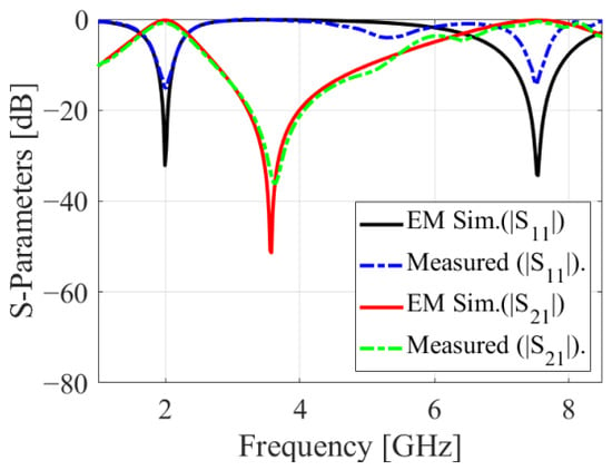
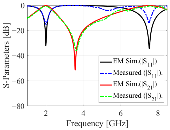
The simulated and measured scattering parameters of the proposed dual-band HMSIW BPF are presented in Figure 21. The measured response confirms the two intended operating bands centered at 2.03 GHz and 7.54 GHz. The measured (simulated) insertion losses at 2.03 GHz and 7.5 GHz are 0.84 dB (0.23 dB) and 0.52 dB (0.21 dB), respectively. Similarly, the measured (simulated) reflection coefficients at 2.03 GHz and 7.5 GHz are −15.2 dB (−28.8 dB) and −17.9 dB (−34.3 dB), respectively. The measured (simulated) 3 dB fractional bandwidths at 2.03 GHz and 7.5 GHz are 29% (32.5%) and 21.6% (25.3%), respectively. A close correspondence can be seen between the simulated and measured responses in terms of resonant-frequency locations and overall response characteristics. The slight deviations in the measured response can be attributed to practical effects such as fabrication tolerances, connector transitions, soldering imperfections, and material losses. Overall, the experimental results confirm the dual-band filtering performance of the developed HMSIW BPF.
Figure 21.
Simulated and measured scattering parameters of the proposed dual-band HMSIW BPF.
4.2. Comparative Analysis
Table 5 presents a comparative assessment of the proposed dual-band HMSIRW filter with previously reported dual-band filtering structures. The designed filter achieves 3 dB fractional bandwidths of 29% and 21.6%, which are considerably higher than those of most reported dual-band filters [1,2,3,4,5,6,7,8,9,10,11,12,13], providing wider passband coverage. In addition, minimal transmission losses of 0.84 and 0.52 dB are obtained, outperforming the reported designs [1,2,3,4,5,6,7,8,9,10,11,12,13]. The return losses of −15.2 and −17.9 dB demonstrate good impedance matching and are higher than those of most of the compared designs. Furthermore, the structure occupies only 0.0064 λg2, providing a substantial size reduction compared with all the reported designs, including the smallest reported value of 0.125λg2 [4]. Overall, the proposed filter offers a miniaturized and efficient approach for dual-band applications.
Table 5.
State-of-the-art performances of the suggested and reported HMSIW dual-band filters.
4.3. Experimental Evaluation of the Dual-Band Power Divider
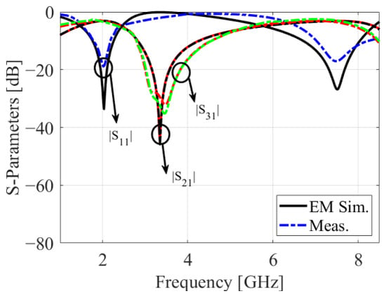
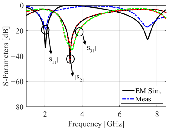
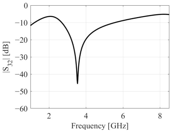
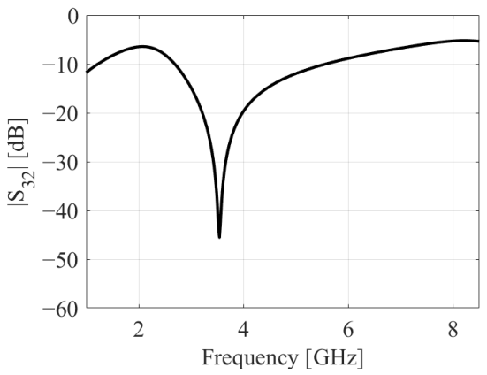
The simulated and measured scattering parameters of the proposed dual-band power divider are presented in Figure 22. The measured response confirms the operating bands centered at 2.03 GHz and 7.5 GHz. The input reflection coefficient |S11| indicates good impedance matching at both operating frequencies, while the transmission coefficients |S21| and |S31| exhibit closely matched responses, confirming the intended equal power-division characteristics between the two output ports. The measured insertion losses are approximately 3.4 dB and 3.6 dB, with corresponding return losses of −18.2 dB and −16.8 dB, respectively. Figure 23 shows the EM-simulated isolation (|S32|) of the suggested dual-band power divider. From the figure, it is noticed that the isolation is greater than 6 dB at both the operating bands. The strong correlation between the experimental and EM-simulated responses in terms of resonant-frequency locations and overall scattering characteristics verifies that the dual-band filtering response is maintained in the power divider configuration. The slight deviations observed in the measured response can be attributed to practical effects such as fabrication tolerances, connector transitions, soldering imperfections, and material losses. Overall, the measured results validate the designed dual-band power divider and its filtering performance.
Figure 22.
Simulated and measured scattering parameters of the proposed dual-band PD.
Figure 23.
EM-simulated isolation of the proposed dual-band power divider.
Table 6 compares the proposed dual-band equal power divider with previously reported dual-band power-dividing structures. The proposed configuration achieves a highly compact normalized size of only 0.0064 λg2, which is smaller than the lowest reported size of 0.01 λg2 in [15], demonstrating a significant reduction in circuit footprint while maintaining good 15 dB fractional bandwidths of 8.3% and 5.4% and insertion losses of 3.4 and 3.6 dB at 2.03 GHz and 7.5 GHz, respectively.
Table 6.
State-of-the-art performances of the suggested and reported HMSIW dual-band power divider. #: 15 dB FBW; $: 3 dB FBW.
5. Conclusions
A dual-band HMSIRW bandpass filter and its extension into an equal power divider have been presented, analyzed, fabricated, and experimentally validated. The proposed configuration employs an OSLR with symmetric folded split rectangular arms to realize dual-band operation through sub-cutoff evanescent-mode excitation at 2.03 GHz and 7.5 GHz. The fabricated BPF and PD occupy a highly compact size of 0.0064 λg2, demonstrating a significant size advantage for compact HMSIRW implementations. The BPF exhibits an insertion loss below 0.84 dB and a 3 dB fractional bandwidth exceeding 21.6% at both operating bands. In addition, the transmission zero at 3.6 GHz with a rejection level of −35.8 dB provides strong suppression of unwanted signals between the passbands. The dual-band PD maintains equal power division of 3 ± 0.5 dB and return loss better than −16.8 dB.
The developed equivalent-circuit model and parametric analysis provide further insight into the resonant behavior and the formation of the dual-band response. The measured characteristics of both prototypes show good correlation with the corresponding EM-simulated responses, thereby confirming the effectiveness of the proposed design methodology and its practical realizability. The proposed designs, with their low loss and ultra-compact size, are suitable for integration into L-band and satellite communication applications.
Author Contributions
Conceptualization, C.S. and R.K.B.; methodology, C.S. and R.K.B.; software, C.S. and R.K.B.; validation, C.S. and R.K.B.; formal analysis, C.S. and R.K.B.; investigation, C.S. and R.K.B.; resources, C.S. and R.K.B.; data curation, C.S. and R.K.B.; writing—original draft preparation, C.S. and R.K.B.; writing—review and editing, C.S. and R.K.B.; visualization, C.S. and R.K.B.; supervision, R.K.B.; project administration, R.K.B.; funding acquisition, R.K.B. All authors have read and agreed to the published version of the manuscript.
Funding
This research received no external funding.
Data Availability Statement
The data presented in this study are available on request from the corresponding author. The original contributions presented in this study are included in the article. Further inquiries can be directed to the corresponding author.
Conflicts of Interest
The authors declare no conflicts of interest.
References
- Chen, F.; Song, K.; Hu, B.; Fan, Y. Compact Dual-Band Bandpass Filter Using HMSIW Resonator and Slot Perturbation. IEEE Microw. Wirel. Compon. Lett. 2014, 24, 686–688. [Google Scholar] [CrossRef] [Scilit]
- Li, Y.C.; Wong, H.; Xue, Q. Dual-Mode Dual-Band Bandpass Filter Based on a Stub-Loaded Patch Resonator. IEEE Microw. Wirel. Compon. Lett. 2011, 21, 525–527. [Google Scholar] [CrossRef] [Scilit]
- Chen, X.P.; Wu, K.; Li, Z.L. Dual-Band and Triple-Band Substrate Integrated Waveguide Filters with Chebyshev and Quasi-Elliptic Responses. IEEE Trans. Microw. Theory Tech. 2007, 55, 2569–2578. [Google Scholar] [CrossRef] [Scilit]
- Ieu, W.; Zhou, D.; Zhang, D.; Lv, D. Compact Dual-Mode Dual-Band HMSIW Bandpass Filters Using Source–Load Coupling with Multiple Transmission Zeros. Electron. Lett. 2019, 55, 210–222. [Google Scholar] [CrossRef] [Scilit]
- Zhao, Z.; Peng, C.; Wang, S.; Zhang, L.; Li, K.; Zhu, Y. Enhanced Dual-and Triple-Band Bandpass Filters Using Slot-Line Perturbed HMSIW Resonators. IEICE Electron. Express 2024, 21, 20240544. [Google Scholar] [CrossRef] [Scilit]
- Senior, D.E.; Cheng, X.; Machado, M.; Yoon, Y.K. Single and dual band bandpass filters using complementary split ring resonator loaded half mode substrate integrated waveguide. In Proceedings of the 2010 IEEE Antennas and Propagation Society International Symposium; IEEE: New York, NY, USA, 2010; pp. 1–4. [Google Scholar]
- Song, K.; Zhu, Y.; Zhang, F. Single-and Dual-Band Filtering-Response Power Dividers Embedded SIW Filter With Improved Output Isolation. Sci. Rep. 2017, 7, 3361. [Google Scholar] [CrossRef] [Scilit] [PubMed]
- Zhang, G.; Zhou, X.; Xu, K.D.; Yang, J.; Sun, X.; Xu, B.; Hong, J. Design of Wide-Stopband and Dual-Band Filtering Crossovers Based on Mixed Substrate Integrated Waveguide Cavities. IEEE Trans. Microw. Theory Tech. 2023, 71, 5346–5357. [Google Scholar] [CrossRef] [Scilit]
- Zhou, K.; Zhou, C.X.; Wu, W. Dual-Mode Characteristics of Half-Mode SIW Rectangular Cavity and Applications to Dual-Band Filters with Widely Separated Passbands. IEEE Trans. Microw. Theory Tech. 2018, 66, 4820–4829. [Google Scholar] [CrossRef] [Scilit]
- Dev, A.; Barua, R.; Jahan, N.; Rahman, M.A. Half-Mode SIW-Based Dual-Band Bandpass Filter Using Ridge for X- and Ku-Band Applications. In Proceedings of the 2023 6th International Conference on Electrical Information and Communication Technology (EICT); Springer: Singapore, 2023; pp. 1–5. [Google Scholar]
- Zhao, X.; Zhu, F.; Jiao, M.R.; Sun, L.F.; Chu, P.; Chen, X. Compact Substrate Integrated Waveguide Dual-Band Bandpass Filter with Closely Spaced Passbands and Controllable Bandwidths. IEEE Microw. Wirel. Technol. Lett. 2026, 36, 517–520. [Google Scholar] [CrossRef] [Scilit]
- Zhu, F.; Zhang, Z.; Yu, Y.; Zhao, X. A Miniaturized, Self-Packaged Dual-Band Bandpass Filter Based on SIW Mixed-Mode Cavities. IEEE Microw. Wirel. Technol. Lett. 2026, 36, 1386–1389. [Google Scholar] [CrossRef] [Scilit]
- Zhu, F.; Li, F.; Zhao, X. A Compact and Fully Shielded Dual-Band Bandpass Filter Using Hybrid SIW and Stripline Resonators. IEEE Microw. Wirel. Technol. Lett. 2026, early access. [Google Scholar] [CrossRef] [Scilit]
- Danaeian, M. Novel Single-Layer Dual-Band Half-Mode Substrate Integrated Waveguide Filter and Filtering Power Dividers with Very Compact Sizes. Int. J. RF Microw. Comput.-Aided Eng. 2022, 32, e22951. [Google Scholar] [CrossRef] [Scilit]
- Danaeian, M. Ultra-Compact Dual-Band Half-Mode Substrate Integrated Waveguide Filter and Filtering Power Divider Based on Metamaterial Concept. AEU-Int. J. Electron. Commun. 2021, 139, 153924. [Google Scholar] [CrossRef] [Scilit]
- Moznebi, A.R.; Danaeian, M.; Zarezadeh, E.; Afrooz, K. Ultracompact Two-Way and Four-Way SIW/HMSIW Power Dividers Loaded by Complementary Split-Ring Resonators. Int. J. RF Microw. Comput.-Aided Eng. 2019, 29, e21878. [Google Scholar] [CrossRef] [Scilit]
- Danaeian, M.; Moznebi, A.R.; Afrooz, K. Super Compact Dual-Band Substrate Integrated Waveguide Filters and Filtering Power Dividers Based on Evanescent-Mode Technique. AEU-Int. J. Electron. Commun. 2020, 125, 153348. [Google Scholar] [CrossRef] [Scilit]
- Duraisamy, T.; Barik, R.K.; Sholampettai Subramanian, K.; Kamatchi, S. A Novel SIW Based Dual-Band Power Divider Using Double-Circular Complementary Split Ring Resonators. Microw. Opt. Technol. Lett. 2019, 61, 1529–1533. [Google Scholar] [CrossRef] [Scilit]
- Barik, R.K.; Cheng, Q.S.; Pradhan, N.C.; Sholampettai Subramanian, K. A Compact SIW Power Divider for Dual-Band Applications. Radioengineering 2020, 29, 94. [Google Scholar] [CrossRef] [Scilit]
- Tharani, D.; Selvajyothi, K.; Karthikeyan, S.S. Highly Miniaturized Dual-Band Power Divider Based on HMSIW For 5G/WLAN Applications. IETE J. Res. 2023, 69, 7218–7226. [Google Scholar] [CrossRef] [Scilit]
- Choudhary, D.K.; Chaudhary, R.K. A compact SIW based filtering power divider with improved selectivity using CSRR. In Proceedings of the 2017 Progress in Electromagnetics Research Symposium-Fall (PIERS-FALL); IEEE: New York, NY, USA, 2017; pp. 1334–1337. [Google Scholar]
- Zheng, J.; Zhang, G.; Zhou, X.; Xie, C.; Zhang, Y.; Wang, X.; Yang, J. Dual-Band Filtering Power Divider Based on CSRRS Loaded SIW Cavity. In IEEE Transactions on Circuits and Systems II: Express Briefs; IEEE: New York, NY, USA, 2021; Volume 69, pp. 394–398. [Google Scholar]
- Mirzaei, M.; Sheikhi, A. Design and Implementation of Microstrip Dual-Band Filtering Power Divider Using Square-Loop Resonator. Electron. Lett. 2020, 56, 19–21. [Google Scholar] [CrossRef] [Scilit]
- Chi, P.L.; Chen, Y.M.; Yang, T. Single-Layer Dual-Band Balanced Substrate-Integrated Waveguide Filtering Power Divider For 5G Millimeter-Wave Applications. IEEE Microw. Wirel. Compon. Lett. 2020, 30, 585–588. [Google Scholar] [CrossRef] [Scilit]
- Wang, Y.; Zhou, C.; Zhou, K.; Wu, W. Compact Dual-Band Filtering Power Divider Based on SIW Triangular Cavities. Electron. Lett. 2018, 54, 1072–1074. [Google Scholar] [CrossRef] [Scilit]
- Kumari, G.; Barik, R.K.; Saxena, P.; Karthikeyan, S.S. Compact substrate integrated waveguide power divider with slot-loaded ground plane for dual-band applications. In Proceedings of the 2018 IEEE MTT-S International Microwave and RF Conference (IMaRC); IEEE: New York, NY, USA, 2018; pp. 1–4. [Google Scholar]
- Hai, X.; Chun-Xia, Z.; Bin-bin, L. Design of Filtering Power Divider Based on Half Mode Substrate Integrated Waveguide. In Proceedings of the 2020 International Conference on Microwave and Millimeter Wave Technology, Shanghai, China, 20–23 September 2020; IEEE: New York, NY, USA, 2020; pp. 1–3. [Google Scholar]
- Li, Y.C.; Xue, Q.; Zhang, X.Y. Single-and Dual-Band Power Dividers Integrated with Bandpass Filters. IEEE Trans. Microw. Theory Tech. 2012, 61, 69–76. [Google Scholar] [CrossRef] [Scilit]
- Song, K.; Fan, M.; Fan, Y. Wideband Half-Mode SIW Power Divider with Improved Output Isolation Using Slotline Isolation Technology. IEEE Access 2018, 6, 62029–62036. [Google Scholar] [CrossRef] [Scilit]
- Zhang, Y.; Xu, F. Miniaturized equal power divider using corrugated substrate integrated waveguide. In Proceedings of the 2020 9th Asia-Pacific Conference on Antennas and Propagation (APCAP); IEEE: New York, NY, USA, 2020; pp. 1–2. [Google Scholar]
- Wang, X.; Zhu, X.W.; Tian, L.; Liu, P.; Hong, W.; Zhu, A. Design and Experiment of Filtering Power Divider Based on Shielded HMSIW/QMSIW Technology for 5G Wireless Applications. IEEE Access 2019, 7, 72411–72419. [Google Scholar] [CrossRef] [Scilit]
- Khan, A.A.; Mandal, M.K. Miniaturized Substrate Integrated Waveguide (SIW) Power Dividers. IEEE Microw. Wirel. Compon. Lett. 2016, 26, 888–890. [Google Scholar] [CrossRef] [Scilit]
- Eom, D.S.; Byun, J.; Lee, H.Y. Multilayer Substrate Integrated Waveguide Four-Way Out-of-Phase Power Divider. IEEE Trans. Microw. Theory Tech. 2009, 57, 3469–3476. [Google Scholar] [CrossRef] [Scilit]
- Song, K.; Fan, Y.; Zhang, Y. Eight-Way Substrate Integrated Waveguide Power Divider with Low Insertion Loss. IEEE Trans. Microw. Theory Tech. 2008, 56, 1473–1477. [Google Scholar] [CrossRef] [Scilit]
- Moznebi, A.R.; Afrooz, K. Compact Power Divider Based on Half Mode Substrate Integrated Waveguide (HMSIW) with Arbitrary Power Dividing Ratio. Int. J. Microw. Wirel. Technol. 2017, 9, 515–521. [Google Scholar] [CrossRef] [Scilit]
- Zhao, X.B.; Wei, F.; Zhang, P.F.; Shi, X.W. Mixed-Mode Magic-Ts and Their Applications on The Designs of Dual-Band Balanced Out-of-Phase Filtering Power Dividers. IEEE Trans. Microw. Theory Tech. 2023, 71, 3896–3905. [Google Scholar] [CrossRef] [Scilit]
- Zhu, F.; Hong, W.; Chen, J.X.; Wu, K. Design and Implementation of a Broadband Substrate Integrated Waveguide Magic-T. IEEE Microw. Wirel. Compon. Lett. 2012, 22, 630–632. [Google Scholar] [CrossRef] [Scilit]
- Gatti, R.V.; Ocera, A.; Marcaccioli, L.; Sorrentino, R. A dual band reconfigurable power divider for WLAN applications. In Proceedings of the 2006 IEEE MTT-S International Microwave Symposium Digest; IEEE: New York, NY, USA, 2006; pp. 465–468. [Google Scholar]
- Wu, L.S.; Xia, B.; Mao, J.; Yin, W.Y. A Half-Mode Substrate Integrated Waveguide Ring for Two-Way Power Division of Balanced Circuit. IEEE Microw. Wirel. Compon. Lett. 2012, 22, 333–335. [Google Scholar] [CrossRef] [Scilit]
- Liu, Y.S.; Row, J.S. Back-to-Back Microstrip Antenna Fed with Tunable Power Divider. IEEE Trans. Antennas Propag. 2015, 63, 2348–2353. [Google Scholar] [CrossRef] [Scilit]
- Lakhdhar, S.; Harabi, F.; Gharsallah, A. New Miniaturized Wilkinson Power Divider Based on a New Half Mode Substrate Integrated Waveguide and Q-TL. Indian J. Sci. Technol. 2019, 12, 1–8. [Google Scholar] [CrossRef] [Scilit]
- Tang, C.W.; Hsieh, Z.Q. Design of a Planar Dual-Band Power Divider with Arbitrary Power Division and a Wide Isolated Frequency Band. IEEE Trans. Microw. Theory Tech. 2015, 64, 486–492. [Google Scholar] [CrossRef] [Scilit]

Disclaimer/Publisher’s Note: The statements, opinions and data contained in all publications are solely those of the individual author(s) and contributor(s) and not of MDPI and/or the editor(s). MDPI and/or the editor(s) disclaim responsibility for any injury to people or property resulting from any ideas, methods, instructions or products referred to in the content. |
© 2026 by the authors. Licensee MDPI, Basel, Switzerland. This article is an open access article distributed under the terms and conditions of the Creative Commons Attribution (CC BY) license.