


Abstract
This paper presents a corrugated Vivaldi antenna architecture targeting sub-6 GHz and millimeter-wave frequency bands for 5G CubeSat applications, combining experimental validation at sub-6 GHz with a simulation-based scaling study at 26.5 GHz. Existing CubeSat antenna designs either target a single frequency band or rely on complex metamaterial structures incompatible with nanosatellite fabrication constraints. To address this gap, a single-element corrugated Vivaldi antenna measuring 90 mm × 80 mm is designed, fabricated on FR-4 substrate, and experimentally validated at 3.5 GHz, confirming a wide impedance bandwidth of 2.75 GHz and a peak gain of 9.6 dBi. The strong agreement between CST Studio Suite simulations and measurements validates the electromagnetic solver configuration, which is subsequently applied, as a simulation-based design study, to a geometrically scaled version on Taconic RF-60A substrate operating at 26.5 GHz. The miniaturized single-element version achieves a simulated 17 GHz ultra-wideband response and 6 dBi gain in a 7.32 mm × 6.32 mm footprint. Two- and four-element array configurations at 26.5 GHz demonstrate systematic simulated gain progression to 9 dBi and 13 dBi, respectively, with beamwidth narrowing from 49° to 30°. All 26.5 GHz designs are simulated with lossy copper metallization ( S/m) and are entirely simulation-based; experimental mmWave validation is a designated target for future work. These results establish a validated design and scaling roadmap for corrugated Vivaldi antennas spanning sub-6 GHz and millimeter-wave bands, offering a cost-effective and CubeSat-compatible solution for high-data-rate inter-satellite communication links.
1. Introduction
CubeSats are a class of small satellites that have been utilized in low Earth orbit (LEO) for over two decades, supporting a wide range of applications such as remote sensing, communications, Earth observation, and even television streaming. In recent years, CubeSats have also been launched for deep-space missions, including exploration missions to Mars, the Moon, and Jupiter [1]. The proliferation of small satellite platforms in space enables a more comprehensive understanding of Earth’s systems through versatile, multi-purpose satellite constellations [2,3].
The growing adoption of mid-band 5G around 3.5 GHz creates a strong demand for compact, wideband, and high-gain antennas suitable for CubeSat integration under strict size and cost constraints. Existing designs often target terrestrial base stations or mmWave bands, or rely on complex metamaterial structures, which increase fabrication cost and reduce compatibility with nanosatellites [4,5]. To address this gap, we propose a corrugated Vivaldi antenna on FR-4 with dimensions of 90 × 80 mm, incorporating 11 corrugations per side and a radial stub to enhance matching and bandwidth. The prototype achieves an impedance bandwidth of 2.75 GHz and a peak gain of 9.6 dBi, while maintaining scalability to array configurations. Compared with prior work, the proposed antenna offers a cost-effective, fabrication-friendly, and CubeSat-compatible solution with balanced wideband and high-gain performance.
Integrating millimeter-wave antennas into CubeSat platforms introduces challenges that are qualitatively different from those at sub-6 GHz. At 26.5 GHz and above, substrate dielectric loss becomes a dominant performance limiter, requiring low-loss materials such as Taconic or Rogers laminates in place of the FR-4 commonly used at lower frequencies [6,7]. The compact 1U CubeSat form factor (100 mm × 100 mm × 113.5 mm) imposes severe constraints on antenna footprint, limiting single-element dimensions to the sub-centimeter range and making array integration geometrically challenging [3,8]. Thermal management in the space vacuum environment demands mechanically and thermally stable substrate materials, while the requirement for directional end-fire radiation patterns, necessary for inter-satellite link pointing, favors traveling-wave structures such as the Vivaldi antenna over resonant patch designs [9,10]. These combined constraints have not been simultaneously addressed in most published CubeSat antenna designs, which typically optimize for a single frequency or a single performance metric.
Several techniques have been explored in the literature to improve Vivaldi antenna impedance bandwidth and radiation performance. Metamaterial loading, including split-ring resonators and corrugated structures, has been applied to broaden bandwidth and enhance gain beyond what is achievable with conventional tapered slot geometries [5,11,12]. Superstrate-based approaches, where a high-permittivity layer is placed above the radiating aperture, can yield significant gain increases at a moderate fabrication cost [13]. Edge modification techniques such as via loading, linearized flare edges, and semi-circular slots [14,15,16] provide additional degrees of freedom for impedance matching and bandwidth extension. Corrugated Vivaldi array designs have also been extended to address mutual coupling suppression between array elements, with notch structures and absorber-based techniques achieving up to 35–53 dB of additional isolation [17,18]. Multi-element array scaling of corrugated structures has been demonstrated at both sub-6 GHz and mmWave frequencies, showing consistent gain and beamwidth improvements [19,20]. While each of these methods improves individual parameters, none has been applied to a CubeSat-targeted corrugated Vivaldi architecture that combines: (i) experimental validation at sub-6 GHz on a standard PCB substrate; (ii) a rigorous electromagnetic scaling methodology transitioning to a low-loss mmWave substrate; and (iii) a systematic simulation-based array scaling study at 26.5 GHz. Prior corrugated Vivaldi studies at mmWave frequencies [11,12] target terrestrial phased arrays on all-metal or Rogers substrates and do not address CubeSat size constraints or sub-6 GHz experimental grounding. Prior CubeSat antenna surveys [3] and Ka-band Vivaldi arrays [21,22] do not provide the sub-6 GHz-to-mmWave scaling link with a fabrication-validated baseline. This work occupies that specific gap.
As demand increases for high-data-rate inter-satellite communication links, there is a growing need for compact, high-performance antenna systems capable of supporting next-generation technologies such as 5G. One promising approach involves the design of miniaturized antipodal Vivaldi antennas (AVA), which combine wideband performance, high gain, and end-fire radiation characteristics, making them suitable for CubeSat integration [4]. For instance, the AVA proposed in [4] operates across three distinct frequency bands, 24.91–33.18 GHz, 34.95–36.58 GHz, and 38.34–39.38 GHz, delivering gains between 8.47 and 12.63 dBi. Corrugation techniques applied to the antenna further enhance its performance [5].
Azari et al. [23] introduced a compact, gain-enhanced Vivaldi antenna with a footprint of 5.5 mm × 12 mm, covering a measured bandwidth of 22.5–45 GHz and simulated extension up to 70 GHz. The antenna demonstrates stable end-fire radiation patterns with a measured gain exceeding 5 dBi, making it compatible with 5G frequency bands such as n257–n261. Fernandez-Martinez et al. [24] proposed a wideband Vivaldi antenna targeting 5G base station deployment, achieving return losses below dB and symmetric beam patterns with gain exceeding 7 dB.
Li et al. [14] presented a high-gain, ultra-wideband AVA using vias-loaded linearized edges achieving a reflection coefficient below dB from 22–40 GHz, with a peak gain of 12.1 dBi at 36 GHz. Reddy et al. [13] introduced a superstrate-based Vivaldi antenna delivering a peak gain of 17 dBi at 10 GHz across a 6–20 GHz wideband range. Further advancements include a dual-polarized modular array reported by Kähkönen et al. [21], operating between 26.5–29.5 GHz with beam steering up to and a realized gain of 19.8 dBi. Pashaki et al. [11] introduced a compact all-metal corrugated array covering 26–30 GHz with high radiation efficiency and reduced inter-element coupling. The growing demand for compact mmWave antenna solutions in 5G systems has prompted comprehensive reviews of design strategies and performance metrics [25,26]. MIMO architectures at mmWave frequencies have attracted significant attention, with recent designs demonstrating high isolation, wide bandwidth, and strong diversity performance at 28 and 38 GHz [27,28,29,30].
The specific contributions of this work are as follows:
- A corrugated Vivaldi antenna on FR-4 operating at 3.5 GHz with a 2.75 GHz impedance bandwidth and 9.6 dBi peak gain, validated by fabrication and measurement, demonstrating compatibility with the 1U CubeSat form factor.
- An electromagnetic-scaling-based miniaturization methodology producing a 7.32 mm × 6.32 mm Vivaldi antenna at 26.5 GHz on Taconic RF-60A, achieving a 17 GHz ultra-wideband response in simulation.
- A systematic array scaling study (1-, 2-, and 4-element configurations at 26.5 GHz) demonstrating gain progression from 6 to 13 dBi, beamwidth narrowing from 49° to 30°, and axial ratio at the design frequency of 2.5, 2.8, and 2.5 dB, respectively (updated from copper metallization simulations), establishing a design roadmap for CubeSat mmWave arrays.
Section 2 details the antenna design process and parametric analysis. Section 3 presents simulation results for the 26.5 GHz configurations. Section 4 compares simulation outcomes with experimental measurements for the 3.5 GHz prototype and presents the state-of-the-art comparison. Section 5 offers conclusions and future research directions.
2. Design of Vivaldi Antennas
The antenna design targets a central frequency of 3.5 GHz, which lies within the 2–5 GHz spectrum encompassing important mid-band 5G allocations such as Band n77 (3.3–4.2 GHz) and Band n78 (3.3–3.8 GHz) [31]. This frequency range is globally significant due to its balanced trade-off between high data throughput, reliable signal penetration, and wide-area coverage [32], making it the most widely deployed 5G band across Europe, Asia, and North America [33].
Selecting 3.5 GHz ensures compatibility with a range of modern wireless systems, including 5G base stations [34], Internet of Things (IoT) networks [35], and inter-satellite communications in nanosatellite platforms [10]. Additionally, the relatively low atmospheric attenuation at this frequency [6], combined with favorable propagation characteristics in suburban and urban environments [36], makes the band particularly attractive for beyond-5G and 6G applications.
The broad bandwidth available in this spectrum also supports high spectral efficiency and carrier aggregation [37], which is crucial for emerging CubeSat constellations demanding reliable inter-satellite links [9]. Consequently, this band has become a primary focus for the design of compact, high-gain, and wideband antennas, where Vivaldi-based structures have demonstrated excellent performance due to their inherent ultra-wideband characteristics and ability to maintain stable radiation patterns [15].
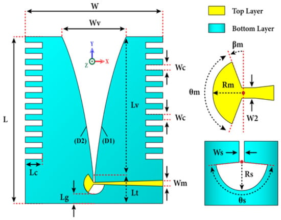
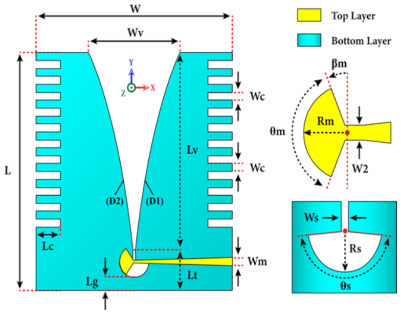
The proposed corrugated Vivaldi antenna was designed using CST Studio Suite [38], a widely used electromagnetic solver validated in numerous antenna studies [39]. The antenna measures 90 mm × 80 mm and consists of two symmetrical exponential flares incorporating 11 corrugations on each side, enhancing impedance matching and broadening the bandwidth [39]. A radial stub on the front side is included to facilitate effective feeding and minimize reflection losses. Figure 1 illustrates the antenna geometry and highlights the key parameters used in the design. In Figure 2a, the top layer shows the tapered exponential flare geometry and the corrugation slots along the flare edges. Figure 2b shows the bottom layer, which carries the radial stub feed structure responsible for the microstrip-to-slot transition.
Figure 1.
Illustration of the designed corrugated Vivaldi antenna with exponential flares and parametric configuration.
Figure 2.
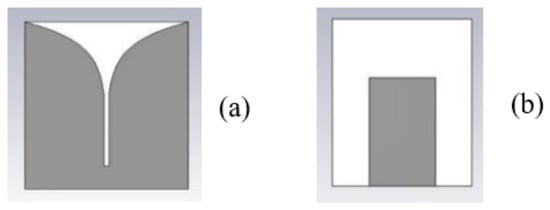
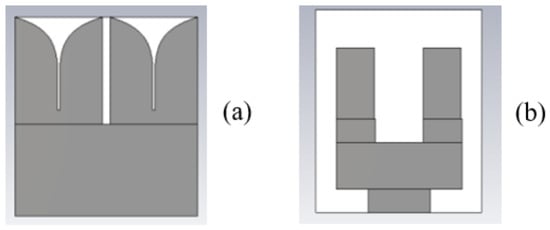
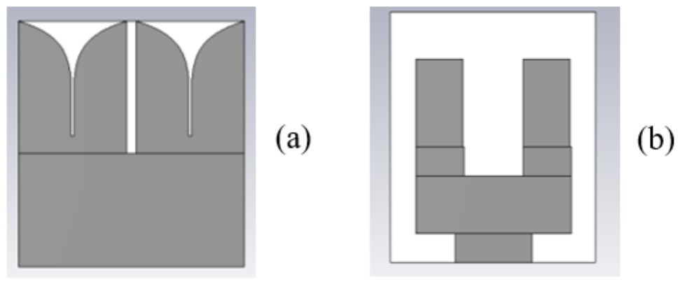
(a) Top layer; (b) bottom layer of the miniaturized single-element Vivaldi antenna at 26.5 GHz.
This work builds upon our preliminary investigation reported in [40], which introduced an initial high-gain Vivaldi antenna concept for 5G CubeSat applications. The present study substantially extends that work by introducing corrugation-based bandwidth enhancement, a validated electromagnetic scaling methodology for 26.5 GHz operation, and a systematic array scaling study covering 1-, 2-, and 4-element configurations with full simulation-to-measurement validation.
2.1. CubeSat Compatibility Assessment
The proposed antenna designs are evaluated against key CubeSat-specific integration constraints. The standard 1U CubeSat form factor defines a maximum envelope of 100 mm × 100 mm × 113.5 mm with a mass limit of 1.33 kg [10]. The 3.5 GHz single-element antenna (90 mm × 80 mm) fits within the lateral face of a 1U CubeSat with minimal margin, making it suitable for deployment on a deployable panel. At 26.5 GHz, the miniaturized designs are sub-centimeter in footprint (7.32 mm × 6.32 mm for a single element), which is entirely compatible with integration on the CubeSat body or within a phased array panel.
In terms of mass, the FR-4 substrate at 0.254 mm thickness and the Taconic RF-60A substrate at 1.6 mm thickness both contribute negligible mass relative to the 1U budget. Thermal stability is addressed through substrate selection: FR-4 has a glass transition temperature of approximately 130 °C, which is adequate for LEO thermal cycling (approximately −40 °C to +80 °C on the sun-facing side), while Taconic RF-60A offers superior thermal stability with a decomposition temperature exceeding 300 °C [6]. From a radiation pattern perspective, the end-fire directional pattern of the Vivaldi structure is well-suited for inter-satellite link applications where beam pointing toward a specific orbital target is required.
It must be acknowledged, however, that practical CubeSat integration involves several challenges not addressed in the present simulation study. These include: (i) deployment mechanism design, as a flush-mounted antenna on a CubeSat face would require a deployable boom or hinge mechanism to clear the solar panels; (ii) satellite-body electromagnetic interaction, where the conductive CubeSat chassis may perturb the end-fire pattern and reduce front-to-back ratio; (iii) coexistence with solar panels covering adjacent faces, which constrains the available radiating aperture and may require spatial or frequency coordination; (iv) attitude control coupling, since the highly directional beam requires attitude knowledge accurate to within the HPBW (49° for the single element, 30° for the 4-element array) to maintain inter-satellite link closure; and (v) link budget closure, which depends on transmit power, free-space path loss at the inter-satellite range, and receiver sensitivity. These integration challenges are identified as the focus of future work and do not diminish the relevance of the electromagnetic performance demonstrated here.
2.2. Electromagnetic Scaling and Validation Methodology
The design strategy in this work follows a two-stage approach. In the first stage, a 3.5 GHz prototype is fabricated and measured to validate the CST simulation environment, specifically the solver boundary conditions, mesh density settings, material models (FR-4 lossy with , ), and port excitation. The strong agreement between simulation and measurement at 3.5 GHz ( within 3 dB across the band, radiation patterns consistent at 3.5, 3.8, and 5.5 GHz as shown in Section 4) provides confidence that the CST solver setup accurately captures the antenna’s electromagnetic behavior. In the second stage, this validated solver configuration is applied to a geometrically scaled design targeting 26.5 GHz. The scaling is performed using the electromagnetic similarity principle, where the characteristic length L of the structure is inversely proportional to frequency for a given effective permittivity:
where c is the speed of light in free space ( m/s), f is the target frequency (26.5 GHz), and is the effective dielectric constant of the substrate–conductor structure. Since the scaling transitions from FR-4 () to Taconic RF-60A (, ), both the frequency ratio and the permittivity ratio govern the scaled dimensions; a simple geometric scaling by the frequency ratio alone would be insufficient. The effective permittivity for the microstrip-like feed region was estimated using the standard quasi-static approximation for a narrow slot on a grounded dielectric slab; for the wide-aperture radiating region, the dominant dielectric contribution diminishes, and the free-space wavelength becomes the primary scaling reference. Accordingly, the overall antenna dimensions were scaled by the factor , evaluated numerically from the substrate parameters above. The substrate thickness at 26.5 GHz was set to 1.6 mm, chosen to maintain a comparable electrical thickness () to the 3.5 GHz prototype, where is the guided wavelength. The number of corrugations per side was kept constant at 11, as the corrugation period scales proportionally with the overall antenna dimensions; the corrugation depth and width were also scaled by the same linear factor, preserving the ratio of corrugation depth to local wavelength. The 26.5 GHz results presented in Section 3 are therefore entirely simulation-based; experimental validation at mmWave frequencies is identified as a target for future work. The exponential taper profile used in both the 3.5 GHz and 26.5 GHz designs is described below. At 26.5 GHz, a μm dimensional tolerance on a 7.32 mm antenna () is expected to shift the resonance frequency by approximately MHz, which is small relative to the 17 GHz operating bandwidth and confirms robustness to standard PCB process variation.
where the parameter a controls the flare opening rate, and sets the initial width of the aperture. Note that is a geometric parameter distinct from the speed of light c used in Equation (1). The taper profile is optimized to ensure broadband impedance matching and a smooth transition from the microstrip feed to the radiating slot. Corrugations are introduced along the flared edges to suppress surface currents, enhance gain, and improve radiation directivity across the operating band.
Taconic RF-60A (lossy) is chosen as the substrate material for the 26.5 GHz designs due to its relative permittivity of , low dissipation factor (tan), and favorable mechanical and thermal properties. These characteristics are essential for minimizing dielectric losses at millimeter-wave frequencies and maintaining structural integrity in space-limited CubeSat environments. In contrast to conventional FR-4, Taconic substrates offer significantly lower dielectric loss, which becomes critical at high operating frequencies.
Figure 2 shows the top and bottom views of the miniaturized single-element Vivaldi antenna designed for 26.5 GHz. Subfigure (a) shows the top metallization layer carrying the tapered slot structure with corrugated edges, while subfigure (b) shows the bottom layer with the waveguide port excitation region. The antenna dimensions are 7.32 mm × 6.32 mm, and the substrate thickness is 1.6 mm. A waveguide port is employed on the bottom layer to ensure efficient excitation. All 26.5 GHz simulations in this work use lossy copper metallization ( S/m, standard roughness model). The effect of conductor loss on efficiency and radiation pattern is quantified in Section 3.1, Section 3.2 and Section 3.3 and compared against the PEC upper bound.
Material selection and geometric optimization were carried out through comparative simulations involving various substrates and taper configurations. The Taconic-based structure demonstrated the best trade-off between return loss (), gain, and bandwidth.
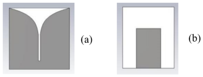
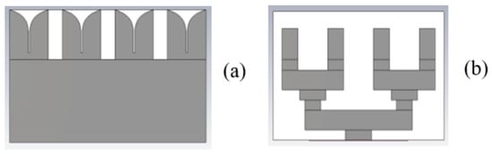
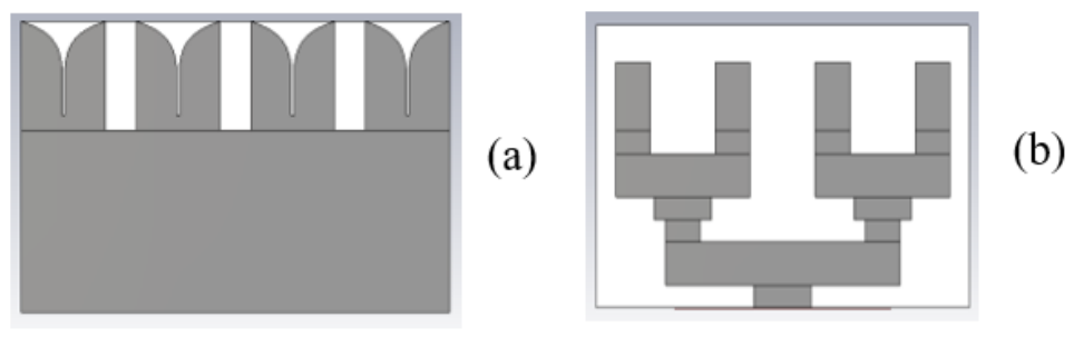
Figure 3 and Figure 4 present the layouts of the 2-element and 4-element Vivaldi antenna arrays, respectively. The 2-element array measures 13.53 mm × 13.32 mm and is designed to minimize mutual coupling while enhancing overall gain. The 4-element array, measuring 32.27 mm × 12.26 mm, maintains consistent feeding and phase coherence among elements, facilitating directive beam formation, critical for high-frequency CubeSat communications.
Figure 3.
(a) Top layer; (b) bottom layer of the 2-element Vivaldi antenna array.
Figure 4.
(a) Top layer; (b) bottom layer of the Vivaldi antenna array.
3. Simulation and Numerical Results
All 26.5 GHz array configurations in this section use single-port excitation with equal-amplitude, in-phase element feeding, an approximation of a corporate feed topology. This approach does not model the insertion loss of a physical power divider network; a realistic Wilkinson-divider corporate feed at Ka-band would contribute an estimated 0.5–1.5 dB of additional loss per power division stage. The reported efficiency values are therefore upper bounds relative to a complete integrated feed implementation. Active reflection coefficient and beam scan characterization require independent per-element phase control and are designated as future work.
3.1. One-Element Configuration
To validate the performance of the proposed miniaturized Vivaldi antenna, full-wave electromagnetic simulations were conducted using CST Studio Suite 2024 [38]. The results include return loss (), radiation patterns, gain, beamwidth, radiation efficiency, axial ratio, and polarization characteristics. Simulations were performed over the 10–40 GHz range, with a design frequency centered at 26.5 GHz.
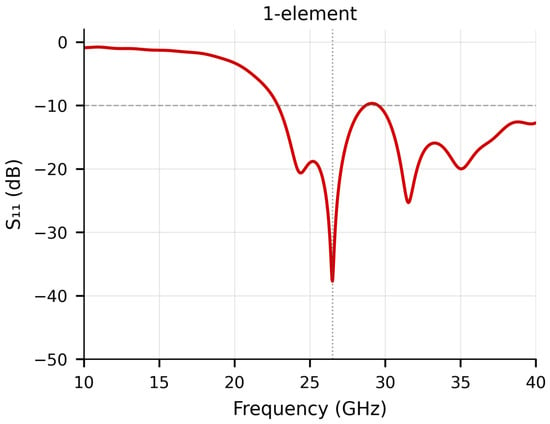
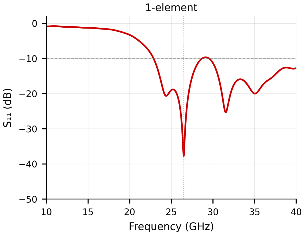
Figure 5 shows the variation in for the single-element antenna. The structure exhibits an ultra-wideband (UWB) response, spanning from 23 GHz to 40 GHz (17 GHz bandwidth), with excellent impedance matching at 26.5 GHz where dB.
Figure 5.
Simulated return loss () of the single-element Vivaldi antenna over 10–40 GHz.
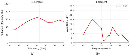
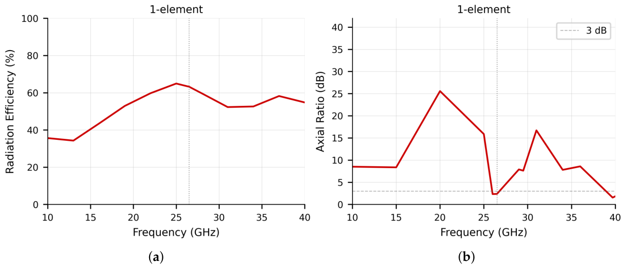
Simulated radiation efficiency at 26.5 GHz with copper metallization ( S/m) is 63%. This is confirmed as substrate-loss dominated: the PEC simulation yields 64%, so conductor loss contributes only 1 percentage point, and the remaining ∼37% efficiency deficit relative to a lossless structure is attributable to dielectric loss in the Taconic RF-60A substrate () integrated over the antenna’s current distribution at 26.5 GHz. The antenna radiates in predominantly linear polarization, as governed by the transverse electric field in the tapered-slot aperture, a fundamental property of the traveling-wave Vivaldi geometry. The axial ratio at the design frequency is ∼2.5 dB, which is near and slightly below the 3 dB LP/CP boundary. This occurs specifically at the 26.5 GHz resonance (where dB), where the redistribution of surface currents near the deep impedance null can enhance cross-polarized field components. Across the remainder of the operating band (10–25 GHz and 30–40 GHz), the AR ranges from 8 to 25 dB, confirming the antenna’s fundamentally linear-polarization character. The AR is retained as a supplementary polarization purity indicator, not a primary metric; the 3 dB reference line is shown explicitly in Figure 6b.
Figure 6.
(a) Simulated radiation efficiency; (b) axial ratio of the single-element antenna.
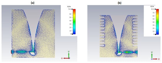
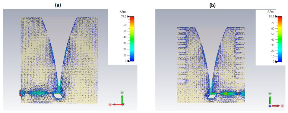
To support the claim that corrugations improve current distribution and radiation performance, Figure 7 presents the simulated surface current distributions at 3.5 GHz for two cases: (a) a flat-edge baseline without corrugations and (b) the proposed corrugated Vivaldi antenna with 11 corrugations per side. The corrugations suppress edge currents along the flare boundaries and confine the radiating aperture to the central slot region, promoting end-fire directional radiation and reducing back-radiation contributions. This mechanism directly accounts for the gain improvement and sidelobe suppression observed in the validated 3.5 GHz prototype.
Figure 7.
Simulated surface current distributions at 3.5 GHz: (a) flat-edge baseline without corrugations; (b) proposed corrugated Vivaldi antenna with 11 corrugations per side.
Figure 6 shows the radiation efficiency and axial ratio as a function of frequency for the single-element configuration with copper metallization, over 10–40 GHz. The radiation efficiency peaks at approximately 65% near 25 GHz and reaches 63% at the design frequency of 26.5 GHz. Figure 6b shows the axial ratio with the 3 dB LP/CP reference line. The AR is above 8 dB across most of the band, confirming linear polarization behavior. The dip to ∼2.5 dB at 26.5 GHz coincides with the deep resonance and is discussed in Section 3.1. These frequency-domain plots complement the single-frequency values reported in Table 1.
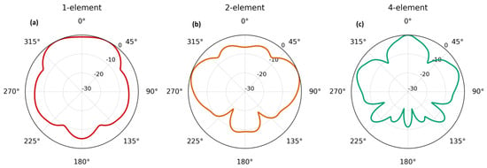
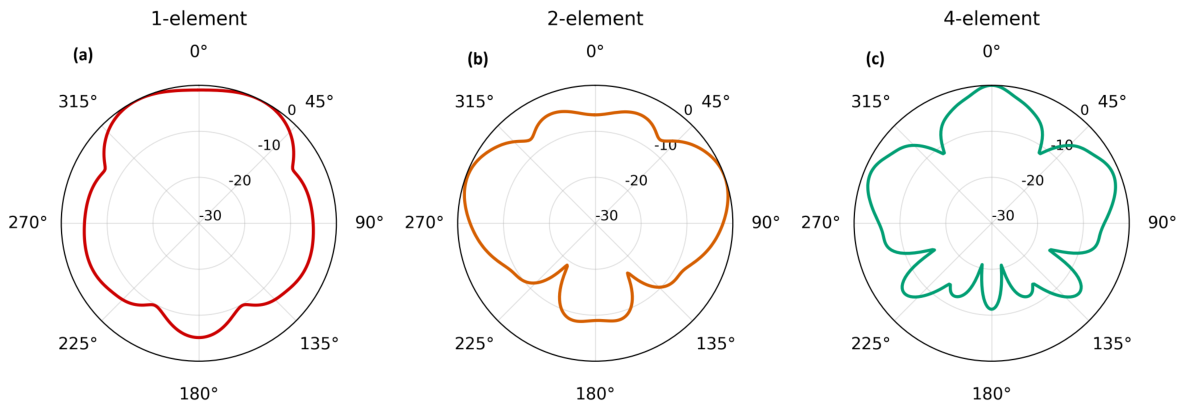
The far-field radiation pattern of the single-element antenna at 26.5 GHz with copper metallization is shown in Figure 12a. The antenna exhibits a directional end-fire beam with a gain of approximately 6 dBi, HPBW of 49°, and sidelobe levels around dB. The 3D radiation pattern screenshots present in the original submission have been removed and replaced with the 2D cuts in Figure 12, which correctly represent the directional characteristics without the coordinate frame ambiguity of the original CST screenshots.
3.2. Two-Element Array Configuration
To improve the gain and beam control, a two-element Vivaldi antenna array was designed. The elements are spaced by 5.66 mm, approximately equal to half a wavelength () at 26.5 GHz. This spacing is derived from:
where d is the center-to-center spacing, c is the speed of light, and GHz. This choice balances mutual coupling and array gain while preventing grating lobes.
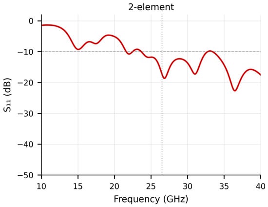
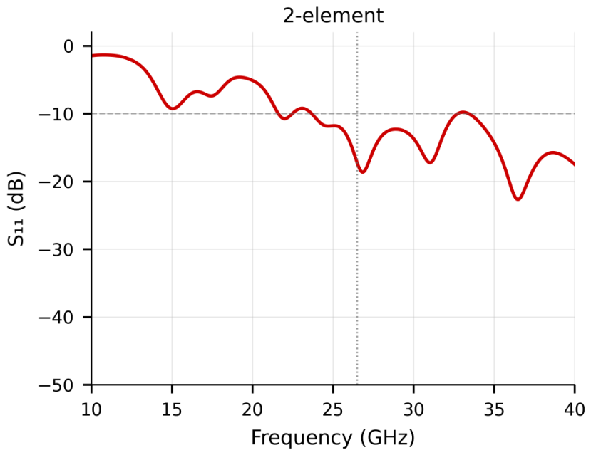
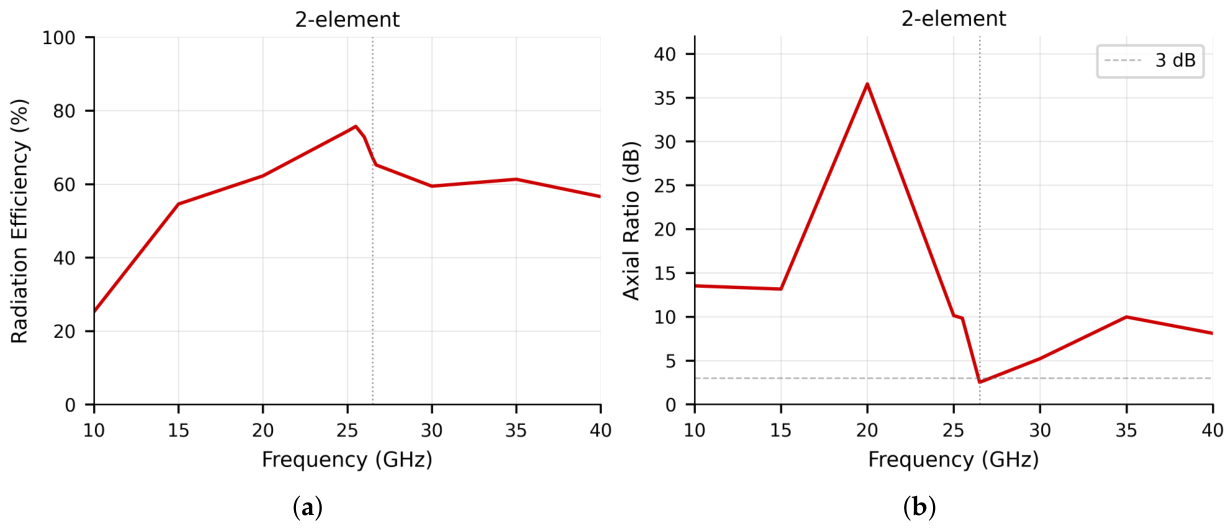
Figure 8 displays the result of the 2-element array, showing a wide operating band from 21.6 GHz to 40 GHz (18.4 GHz bandwidth). The far-field radiation pattern of the 2-element array at 26.5 GHz is shown in Figure 12b. The gain improves to 9 dBi, the HPBW narrows to 42°, and sidelobes are suppressed to dB. The radiation efficiency at 26.5 GHz is 65%, and the axial ratio at the design frequency is 2.8 dB, indicating operation near the linear-polarization boundary (AR dB is fully LP). These AR values are reported as auxiliary polarization purity indicators only; the antenna is not designed for circular polarization.
Figure 8.
Simulated return loss () of the 2-element array over 10–40 GHz.
Figure 9 presents radiation efficiency and axial ratio vs. frequency for the 2-element configuration. The radiation efficiency of the 2-element array reaches 65% at 26.5 GHz, consistent with the improvement expected from increased aperture utilization. The axial ratio is 2.8 dB at 26.5 GHz, near the 3 dB LP/CP boundary, consistent with the resonance-driven behavior discussed in Section 3.1; it is provided for completeness as a secondary polarization metric.
Figure 9.
(a) Simulated radiation efficiency; (b) axial ratio of the 2-element array.
3.3. Four-Element Array Configuration
To further enhance gain, directivity, and beam shaping, a 4-element Vivaldi array was simulated. The inter-element center-to-center spacing is mm, where is the free-space wavelength at 26.5 GHz. This value is consistent with the spacing adopted for the 2-element configuration and is derived from Equation (3).
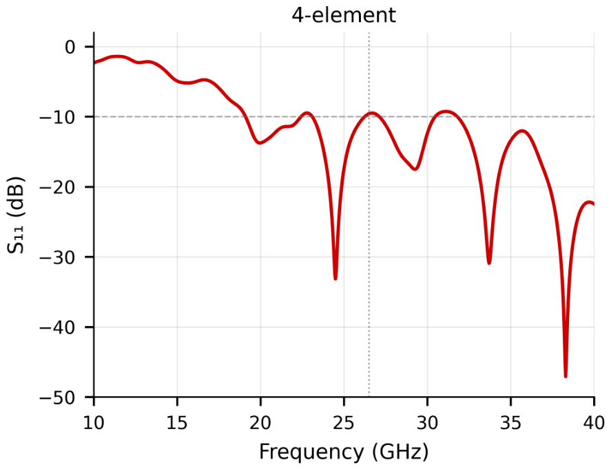
The parameter is presented in Figure 10, showing a UWB response from 19 GHz to 40 GHz, an effective bandwidth of 21 GHz, exceeding that of the 1- and 2-element configurations.
Figure 10.
Four-element array return loss over 10–40 GHz.
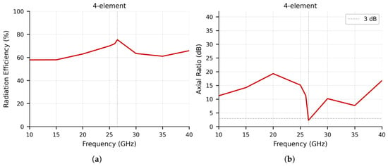
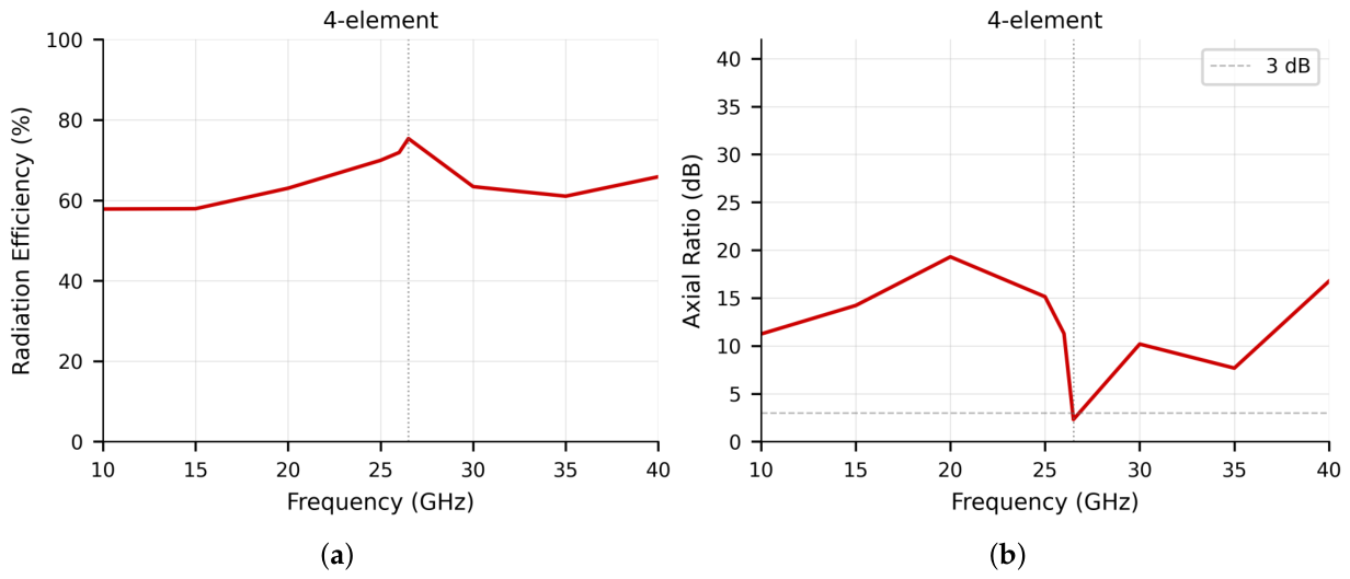
Figure 11 presents the radiation efficiency and axial ratio vs. frequency for the 4-element configuration with copper metallization. The 4-element array achieves the highest efficiency among the three configurations, reaching 75% at 26.5 GHz. This improvement relative to the 1- and 2-element cases is consistent with the larger effective radiating aperture, which reduces the proportion of power dissipated in the substrate per unit of radiated power. The axial ratio at 26.5 GHz is approximately 2.5 dB, near the 3 dB LP/CP boundary as discussed in Section 3.1. Across the remainder of the operating band, the AR exceeds 10 dB, confirming the antenna’s linearly polarized character.
Figure 11.
(a) Simulated radiation efficiency; (b) axial ratio of the 4-element array.
The E-plane () radiation pattern at 26.5 GHz is shown in Figure 12. The peak gain reaches 13 dBi, the HPBW narrows to 30°, and sidelobe levels are reduced to dB, the tightest beam and highest gain among the three configurations studied. The simulation results confirm that the proposed Vivaldi antenna architecture scales systematically with element count, delivering consistent improvements in gain, beamwidth, and radiation efficiency. A full comparative analysis across all configurations and against state-of-the-art designs is provided in Section 4. The following section presents the experimental validation of the 3.5 GHz prototype, which underpins the simulation methodology applied to all 26.5 GHz results above.
Figure 12.
Simulated E-plane () far-field radiation patterns at 26.5 GHz with copper metallization: (a) 1-element, (b) 2-element, and (c) 4-element configurations. The end-fire direction is along the axis (). The 3 dB beamwidth narrows progressively from 49° to 42° to 30° as the element count increases.
4. Measurement Results and Comparative Analysis
4.1. Fabrication and Validation
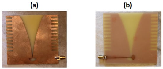
In order to validate the CST simulation framework used for all designs in this work, the corrugated Vivaldi antenna was fabricated and measured at 3.5 GHz. Figure 13 presents the top and bottom metallic layers of the fabricated corrugated Vivaldi antenna: subfigure (a) shows the top copper layer carrying the exponential flare and corrugation geometry, and subfigure (b) shows the bottom copper layer with the radial stub feed. Both layers are made of copper with a thickness of 17.5 μm, while the dielectric substrate is FR-4 (lossy) with a thickness of 0.254 mm. The antenna’s reflection coefficient () was measured using a Keysight N9918A FieldFox Vector Network Analyzer (VNA) (Santa Rosa, CA, USA), covering the 2–6 GHz range. Before testing, a standard Open–Short–Load (OSL) calibration was performed to ensure accuracy. The antenna was connected to the VNA via a high-quality coaxial cable, soldered to an SMA connector directly attached to the feed line.
Figure 13.
(a) Top layer; (b) bottom layer of the fabricated corrugated Vivaldi antenna at 3.5 GHz.
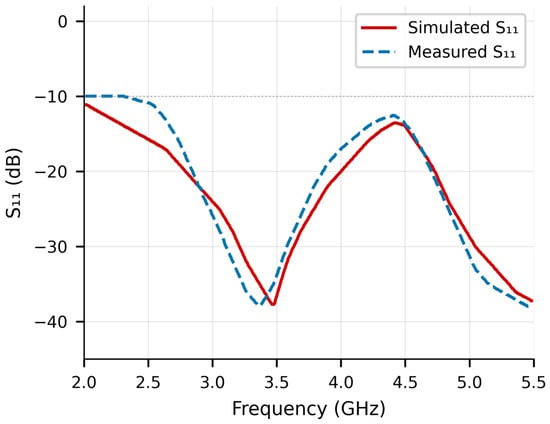
Figure 14 compares the simulated and measured results. The frequency range of interest extends from 2 to 5.5 GHz, covering Band 6 of the 5G spectrum with a central frequency at 3.5 GHz. Both simulation and measurement confirm the wideband performance and strong impedance matching of the antenna. At 3.5 GHz, the simulated reaches approximately dB, while the measured value is dB. At 3.8 GHz, the simulated and measured values are dB and dB, respectively. Even at the upper limit (5.5 GHz), both approaches maintain excellent matching, with values around dB.
Figure 14.
Comparison between obtained via CST simulation (blue curve) and measurement (orange curve).
The observed discrepancies between simulation and measurement warrant a structured analysis. Four contributing factors are identified. First, the SMA connector and soldering joint introduce a feed discontinuity that is not modelled in simulation; insertion loss from the connector is estimated at 0.3–0.5 dB, which shifts the measured minima and alters the impedance trajectory in the Smith chart sense. Second, commercial FR-4 PCB substrates carry a thickness tolerance of approximately and a permittivity variation of across the board; these combined tolerances are sufficient to shift resonance frequencies by 50–100 MHz and alter the depth by 2–4 dB at deep nulls. Third, the measurement environment is not an anechoic chamber; reflections from the measurement bench, cable routing, and antenna support structure contribute spurious signals that perturb the measured below dB. Fourth, the connector soldering quality and coaxial cable flexibility introduce phase errors that manifest as apparent frequency shifts in the measured response. Despite these factors, the overall agreement is strong: the dB bandwidth is correctly captured in both simulation and measurement, and the principal resonance at 3.5 GHz is reproduced within 3 dB.
The analysis of the response across the operational band confirms consistent impedance matching from 2.5 to 5.5 GHz. At the central frequency of 3.5 GHz, the strong resonance confirms that the structural and material parameters of the proposed corrugated Vivaldi antenna are well-optimized for the intended operating band. As the frequency increases beyond the central value, the antenna maintains stable performance, with values remaining below dB, demonstrating consistent impedance matching across the upper portion of the band. This behavior highlights the effectiveness of the corrugated design in enhancing current distribution and radiation characteristics over a wide frequency span.
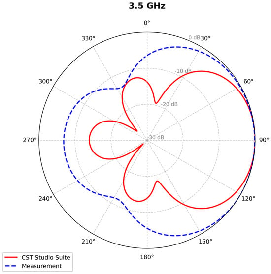
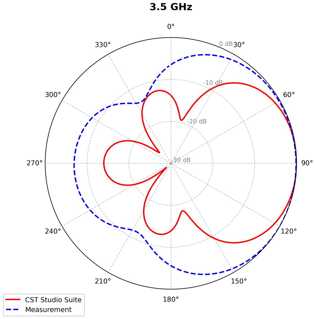
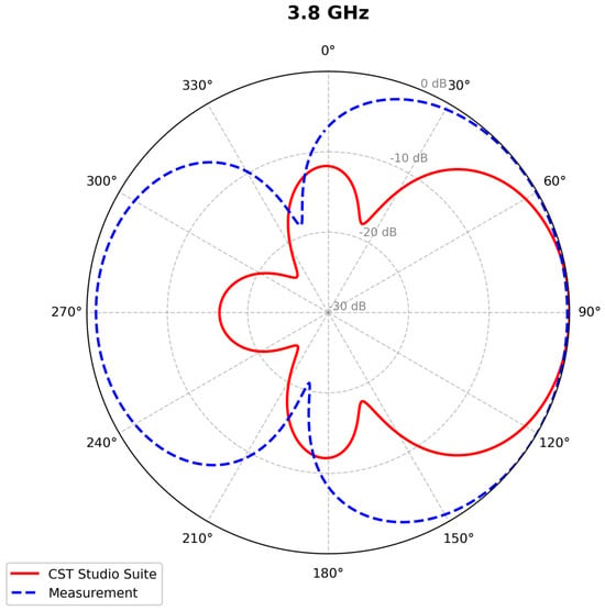
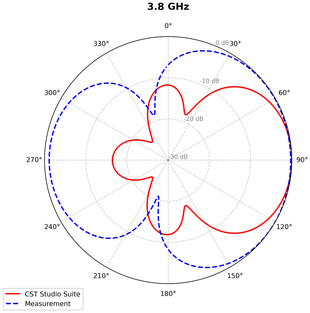
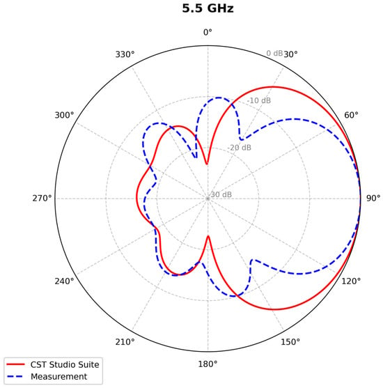
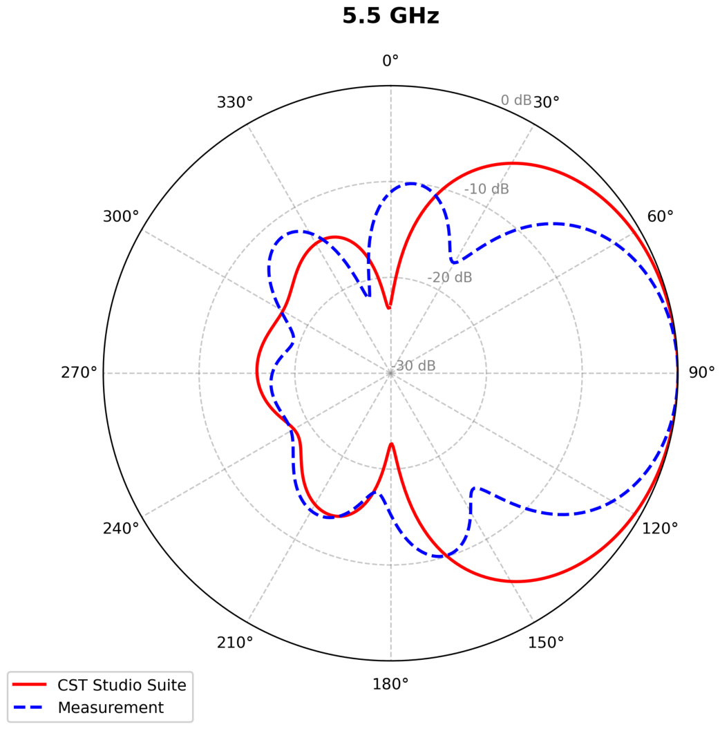
To evaluate the radiation pattern, a dedicated measurement setup was implemented. Two identical corrugated Vivaldi antennas, one acting as the transmitter (Port 1) and the other as the receiver (Port 2), were mounted face-to-face on a fixed support at the same height and separated by 0.88 m. The far-field condition was verified: at 3.5 GHz, the minimum far-field distance is m, well within the 0.88 m separation used, confirming far-field operation across the measurement band. Both antennas were connected via calibrated RF cables, with the transmitter driven by a calibrated signal source and the receiver connected to a power meter. The system was calibrated using the Friis transmission equation: the received power at boresight was first recorded at 0°, then used as the 0 dB reference level for the normalized angular pattern. Measurements were recorded at 10° angular increments from 0° to 180° on the forward hemisphere. Measurement uncertainty is estimated at ±1.5 dB, attributable to cable movement, power meter resolution, and support fixture reflections. For angles from 180° to 360°, the pattern was reconstructed using the same normalized measurements on the complementary half-rotation. The measurement environment is not an anechoic chamber; reflections from the test bench and surrounding structure contribute spurious signals primarily below the dB level of the main beam, which explains the sidelobe discrepancies between measurement and simulation observed in Figure 15, Figure 16 and Figure 17.
Figure 15.
Comparison between far-fields at 3.5 GHz obtained by CST Studio Suite (red curve) and measurement (blue curve).
Figure 16.
Comparison between far-fields at 3.8 GHz obtained by CST Studio Suite (red curve) and measurement (blue curve).
Figure 17.
Comparison between far-fields at 5.5 GHz obtained by CST Studio Suite (red curve) and measurement (blue curve).
The operating frequency band for the measurements spanned 2–5 GHz. The received power was recorded at angular increments of 10°, starting from 0° up to 180°. For angles from 180° to 360°, the power values were normalized accordingly. Radiation patterns were plotted and compared with CST simulation results for three selected frequencies: 3.5 GHz, 3.8 GHz, and 5.5 GHz (Figure 15, Figure 16 and Figure 17, respectively), corresponding to the optimal gain values observed during measurement.
For all three frequencies, the measured and simulated radiation patterns exhibit strong agreement in main beam shape and pointing direction, with discrepancies primarily confined to the sidelobe region. The sidelobe differences, up to 3–4 dB at 3.8 and 5.5 GHz, are attributable to the same environmental and hardware factors discussed in Section 4.1: non-anechoic measurement conditions, cable-induced phase perturbations, and the normalization procedure used to construct the full 360° pattern from half-space measurements. The close correspondence in main beam confirms that the corrugated Vivaldi antenna achieves its intended radiation targets and validates the CST solver for application to the 26.5 GHz designs.
The fabricated corrugated Vivaldi antenna, with its demonstrated radiation characteristics and wideband impedance matching, is a strong candidate for integration into a 1U CubeSat platform for 5G space communication missions.
4.2. Performance Summary and State-of-the-Art Comparison
Table 1 presents the comparative simulation parameters across all four antenna configurations studied in this work, covering the 3.5 GHz single-element design and the three 26.5 GHz configurations.
Table 1.
Comparative summary of all antenna configurations studied in this work in terms of key performance parameters.
Table 2 presents a comparison between the proposed designs and representative state-of-the-art Vivaldi and mmWave antenna designs reported in the literature for 5G and CubeSat applications. The table is organized by design category, single elements, multi-element arrays, MIMO designs, and miniaturized mmWave structures, to avoid direct comparison across configurations with fundamentally different objectives (single elements vs. large arrays, fully measured vs. simulation-only results, and disparate frequency bands). The proposed 3.5 GHz single-element design compares favorably in terms of bandwidth and gain relative to prior corrugated Vivaldi designs at comparable frequencies, including recent broadband and multi-band mmWave patch designs targeting 5G and 6G [41]. At 26.5 GHz, the four-element array achieves 13 dBi gain with a 21 GHz bandwidth, which compares competitively with the modular Ka-band arrays reported in [21,22] despite significantly smaller per-element dimensions. The all-metal corrugated design of [11] achieves higher gain through a configuration, but at substantially greater size and fabrication complexity. From a CubeSat integration perspective, the proposed antennas compare favorably with the comprehensive landscape of CubeSat antenna designs surveyed in [3], offering a combination of wideband performance and mmWave scalability not commonly reported in that domain. The proposed designs occupy a favorable position in the gain–bandwidth–size trade-off space, particularly given their compatibility with standard PCB fabrication for CubeSat integration.
Table 2.
State-of-the-art comparison of Vivaldi and mmWave antenna designs for 5G and CubeSat applications.
5. Conclusions
This work presented a corrugated Vivaldi antenna architecture covering both sub-6 GHz and millimeter-wave frequency bands for 5G CubeSat applications. A 3.5 GHz single-element prototype fabricated on FR-4 demonstrated a 2.75 GHz impedance bandwidth and 9.6 dBi peak gain, with simulation-to-measurement agreement validating the CST solver configuration. This validated framework was applied to geometrically scaled designs at 26.5 GHz on Taconic RF-60A as a simulation-based study, where a single-element antenna achieved a 17 GHz ultra-wideband response in a 7.32 mm × 6.32 mm footprint. Systematic scaling to 2- and 4-element arrays demonstrated gain progression to 9 dBi and 13 dBi, beamwidth narrowing to 42° and 30°, and consistently linear polarization behavior, establishing a clear simulation-based performance roadmap for CubeSat mmWave array design. The 26.5 GHz metallization was modeled with lossy copper ( S/m); the PEC-based values from earlier simulations are acknowledged as upper bounds. Experimental mmWave fabrication and characterization remain as the primary future objective.
Future Studies
Several directions are identified for subsequent work. First, fabrication and experimental characterization of the 26.5 GHz single-element and array designs on Taconic RF-60A using a calibrated mmWave measurement facility is the most critical next step, as it will close the validation gap identified in this study. Second, CST simulations incorporating a full corporate feed network with realistic Wilkinson power divider insertion loss should be performed to close the feed network loss gap not captured by the present single-port element excitation. Third, the 4-element array architecture should be extended to include phase shifters and a corporate feed network with accurate insertion loss modeling, enabling beam steering characterization across the operating band. Fourth, from a CubeSat system perspective, the following environmental qualification aspects are identified for future investigation: (a) vibration survivability of the PCB antenna under launch loads, assessed against standard CubeSat structural test requirements; (b) deployment mechanism design, including hinge or boom concepts compatible with 1U form-factor constraints and release mechanism reliability; (c) thermal-vacuum performance, evaluating substrate dimensional stability and connector integrity across the LEO thermal cycle (−40 °C to +125 °C); (d) radiation hardness assessment of both FR-4 and Taconic RF-60A substrates under accumulated total ionizing dose representative of a 2-year LEO mission; (e) solar panel electromagnetic coexistence, specifically mutual coupling between the antenna and deployed solar cell arrays on adjacent CubeSat faces; and (f) EMC qualification, ensuring the antenna does not degrade the operation of onboard electronics. These studies will be necessary before the proposed architecture can be considered for flight integration.
Author Contributions
R.E.H.C., conceptualization, antenna design, simulations, data analysis, and writing, original draft preparation; E.R., supervision, methodology guidance, critical review, and manuscript editing; S.S., co-supervision, technical validation, critical feedback, and manuscript refinement; G.Z.E.N., co-investigation, RF expertise support, editing of the drafted writing, and contributions to the interpretation of results. All authors have read and agreed to the published version of the manuscript.
Funding
This research received no external funding.
Data Availability Statement
The data supporting the findings of this study are available from the corresponding author upon reasonable request.
Acknowledgments
The authors would like to thank the Doctoral School of Science and Technology (EDST), Lebanese University, and the École Supérieure des Ingénieurs de Beyrouth (ESIB), Saint Joseph University of Beirut, for their continuous support and guidance throughout this research work.
Conflicts of Interest
The authors declare no conflicts of interest. The funders had no role in the design of the study; in the collection, analyses, or interpretation of data; in the writing of the manuscript; or in the decision to publish the results.
Abbreviations
The following abbreviations are used in this manuscript:
| AVA | Antipodal Vivaldi Antenna |
| CST | Computer Simulation Technology |
| CubeSat | Cube Satellite |
| dBi | Decibels relative to isotropic antenna |
| EDST | École Doctorale de Sciences et de Technologie |
| EMC | Electromagnetic Compatibility |
| ESIB | École Supérieure des Ingénieurs de Beyrouth |
| ETSI | European Telecommunications Standards Institute |
| FR-4 | Flame Retardant 4 (substrate material) |
| GHz | Gigahertz |
| GSA | Global Mobile Suppliers Association |
| HPBW | Half-Power Beamwidth |
| IEEE | Institute of Electrical and Electronics Engineers |
| IoT | Internet of Things |
| ITU-R | International Telecommunication Union – Radiocommunication |
| LEO | Low Earth Orbit |
| MIMO | Multiple Input Multiple Output |
| OSL | Open–Short–Load (calibration) |
| PCB | Printed Circuit Board |
| PEC | Perfect Electric Conductor |
| RF | Radio Frequency |
| SLL | Sidelobe Level |
| SMA | Subminiature version A (connector) |
| UWB | Ultra-Wideband |
| VNA | Vector Network Analyzer |
| 1U | 1 Unit (CubeSat standard form factor) |
| 3GPP | 3rd Generation Partnership Project |
| 5G | Fifth Generation (wireless) |
| 6G | Sixth Generation (wireless) |
References
- Space.com. CubeSats: Tiny Satellites for Research and Education. 2016. Available online: https://www.space.com/34324-cubesats.html (accessed on 19 March 2026).
- Radhakrishnan, R.; Edmonson, W.; Afghah, F.; Rodriguez-Osorio, R.; Pinto, F.; Burleigh, S.C. Survey of Inter-Satellite Communication for Small Satellite Systems: Physical Layer to Network Layer View. IEEE Commun. Surv. Tutor. 2016, 18, 2442–2473. [Google Scholar] [CrossRef] [Scilit]
- Abulgasem, S.; Tubbal, F.E.M.; Raad, R.; Theoharis, P.I.; Lu, S.; Iranmanesh, S. Antenna Designs for CubeSats: A Review. IEEE Access 2021, 9, 45289–45324. [Google Scholar] [CrossRef] [Scilit]
- Dixit, A.S.; Kumar, S. A Miniaturized Antipodal Vivaldi Antenna for 5G Communication Applications. In Proceedings of the 7th International Conference on Signal Processing and Integrated Networks (SPIN), Noida, India, 27–28 February 2020; pp. 800–803. [Google Scholar] [CrossRef] [Scilit]
- Kumar, S.; Dixit, A.S. Gain Enhancement of Antipodal Vivaldi Antenna for 5G Applications Using Metamaterial. Wirel. Pers. Commun. 2021, 121, 2667–2679. [Google Scholar] [CrossRef] [Scilit]
- Rappaport, T.S.; Sun, S.; Mayzus, R.; Zhao, H.; Azar, Y.; Wang, K.; Wong, G.N.; Schulz, J.K.; Samimi, M.; Gutierrez, F. Millimeter Wave Mobile Communications for 5G Cellular: It Will Work! IEEE Access 2013, 1, 335–349. [Google Scholar] [CrossRef] [Scilit]
- Din, I.; Alibakhshikenari, M.; Virdee, B.; Jayanthi, R.; Ullah, S.; Khan, S.; See, C.; Golunski, L.; Koziel, S. Frequency-Selective Surface-Based MIMO Antenna Array for 5G Millimeter-Wave Applications. Sensors 2023, 23, 7009. [Google Scholar] [CrossRef] [Scilit] [PubMed]
- Al-Khaffaf, D.; Alshimaysawe, I. Miniaturised Tri-Band Microstrip Patch Antenna Design for Radio and Millimetre Waves of 5G Devices. Indones. J. Electr. Eng. Comput. Sci. 2021, 21, 1594–1601. [Google Scholar] [CrossRef] [Scilit]
- Maleki, F.; AbdollahRamezani, S.; Sadeghzadeh, S.M.; Zamani, H.; Hosseinzadeh, S. CubeSat Communications: Recent Advances and Future Challenges. IEEE Access 2021, 9, 145638–145659. [Google Scholar] [CrossRef] [Scilit]
- Selva, D.; Krejci, D. A survey and assessment of the capabilities of Cubesats for Earth observation. Acta Astronaut. 2012, 74, 50–68. [Google Scholar] [CrossRef] [Scilit]
- Mehri Pashaki, M.; Rezaei, F.; Nourinia, J. Design of a compact corrugated all-metal Vivaldi phased array for 5G millimeter-wave applications. IEEE Access 2025, 13, 31890–31899. [Google Scholar] [CrossRef] [Scilit]
- Pashaki, M.M.; Ghamsari, M.H.K.; Mallahzadeh, A.; Gradoni, G.; Khalily, M. A Corrugated All-Metal Vivaldi Antenna for 5G Phased Array Applications. IEICE Trans. Commun. 2025, E108-B, 870–875. [Google Scholar] [CrossRef] [Scilit]
- Reddy, M.; Sheela, D.; Premalatha, J.; Jayasudha, F. A High Gain Antipodal Vivaldi Antenna Enabled by a High Dielectric Superstrate for Wideband Applications. Int. J. Commun. Syst. 2024, 38, e6028. [Google Scholar] [CrossRef] [Scilit]
- Li, J.; He, H.; Xiong, S.; Feng, G.; Wang, Y. A novel high-gain antipodal Vivaldi antenna for 5G MM-wave applications. AEU-Int. J. Electron. Commun. 2024, 177, 155160. [Google Scholar] [CrossRef] [Scilit]
- Oraizi, H.; Hedayati, S. Miniaturized UWB Vivaldi Antenna Design by Using Semi-Circular Slots. IEEE Antennas Wirel. Propag. Lett. 2011, 10, 67–70. [Google Scholar] [CrossRef] [Scilit]
- Dixit, A.S.; Kumar, S. A Fermi-Dirac Function-Based Antipodal Vivaldi Antenna for mmWave Applications. J. Infrared Millim. Terahertz Waves 2022, 43, 244–259. [Google Scholar] [CrossRef] [Scilit]
- Ramanujam, P.; Ponnusamy, M.; Ramanujam, K. A Compact Wide-Bandwidth Antipodal Vivaldi Antenna Array with Suppressed Mutual Coupling for 5G mm-Wave Applications. AEU—Int. J. Electron. Commun. 2021, 133, 153668. [Google Scholar] [CrossRef] [Scilit]
- Ahmed, A.; Kumari, V.; Sheoran, G. Reduction of Mutual Coupling in Antenna Array Using Metamaterial Surface Absorber. AEU—Int. J. Electron. Commun. 2023, 160, 154519. [Google Scholar] [CrossRef] [Scilit]
- Nasir, M.; Iftikhar, A.; Shafique, M.F.; Saka, B.; Nikolaou, S.; Anagnostou, D.E. Broadband Dual-Podal Multilayer Vivaldi Antenna Array for Remote Sensing Applications. IET Microwaves Antennas Propag. 2023, 17, 505–517. [Google Scholar] [CrossRef] [Scilit]
- Elsharkawy, R.R.; Hussein, K.F.A.; Farahat, A.E. Miniaturized Multi-Band Millimeter-Wave Vivaldi Antenna with Performance Optimization at 28 GHz for 5G MIMO Applications. J. Infrared Millim. Terahertz Waves 2024, 45, 208–232. [Google Scholar] [CrossRef] [Scilit]
- Kähkönen, H.; Berg, M.; Viikari, V. A Modular Dual-Polarized Ka-band Vivaldi Antenna Array. IEEE Trans. Antennas Propag. 2022, 70, 10343–10351. [Google Scholar] [CrossRef] [Scilit]
- Kähkönen, H.; Ala-Laurinaho, J.; Viikari, V. A modular dual-polarized Ka-band Vivaldi antenna array for 18–30 GHz. IEEE Access 2022, 10, 36363–36372. [Google Scholar] [CrossRef] [Scilit]
- Azari, A.; Skrivervik, A.; Aliakbarian, H.; Sadeghzadeh, R.A. A Super Wideband Dual-Polarized Vivaldi Antenna for 5G mmWave Applications. IEEE Access 2023, 11, 80761–80768. [Google Scholar] [CrossRef] [Scilit]
- Fernandez-Martinez, P.; Martin-Anton, S.; Segovia-Vargas, D. Design of a Wideband Vivaldi Antenna for 5G Base Stations. In Proceedings of the IEEE International Symposium on Antennas and Propagation and USNC-URSI Radio Science Meeting, Atlanta, GA, USA, 7–12 July 2019; pp. 149–150. [Google Scholar] [CrossRef] [Scilit]
- Yang, Y.; Mao, M.; Xu, J.; Liu, H.; Wang, J.; Song, K. Millimeter-Wave Antennas for 5G Wireless Communications: Technologies, Challenges, and Future Trends. Sensors 2025, 25, 5424. [Google Scholar] [CrossRef] [Scilit] [PubMed]
- Pachaiyappan, G.; Mane, P.; Kumar, P.; Ali, T.; Alsath, M.H. Planar MIMO Antenna for mmWave Applications: Evolution, Present Status and Future Scope. Heliyon 2023, 9, e13362. [Google Scholar] [CrossRef] [Scilit] [PubMed]
- Khan, D.; Ahmad, A.; Choi, D.Y. Dual-Band 5G MIMO Antenna with Enhanced Coupling Reduction Using Metamaterials. Sci. Rep. 2024, 14, 96. [Google Scholar] [CrossRef] [Scilit] [PubMed]
- Ahmad, A.; Choi, D.Y.; Ullah, S. A Compact Two Elements MIMO Antenna for 5G Communication. Sci. Rep. 2022, 12, 3608. [Google Scholar] [CrossRef] [Scilit] [PubMed]
- Raheel, K.; Altaf, A.; Waheed, A.; Kiani, S.H.; Sehrai, D.A.; Tubbal, F.; Raad, R. E-Shaped H-Slotted Dual Band mmWave Antenna for 5G Technology. Electronics 2021, 10, 1019. [Google Scholar] [CrossRef] [Scilit]
- Khan, J.; Ullah, S.; Ali, U.; Tahir, F.A.; Peter, I.; Matekovits, L. Design of a Millimeter-Wave MIMO Antenna Array for 5G Communication Terminals. Sensors 2022, 22, 2768. [Google Scholar] [CrossRef] [Scilit] [PubMed]
- 3rd Generation Partnership Project (3GPP). NR; Base Station (BS) Radio Transmission and Reception; Technical Report 3GPP TS 38.104, Release 17; ETSI: Sophia Antipolis, France, 2022. [Google Scholar]
- Global Mobile Suppliers Association (GSA). 5G Spectrum Snapshot: Deployment Status and Global Band Allocations; Technical Report; GSA: Surrey, UK, 2023. [Google Scholar]
- International Telecommunication Union (ITU-R). Frequency Arrangements for Implementation of the Terrestrial Component of IMT; Technical Report Report M.1036-6; ITU: Geneva, Switzerland, 2021. [Google Scholar]
- Andrews, J.G.; Buzzi, S.; Choi, W.; Hanly, S.V.; Lozano, A.; Soong, A.C.K.; Zhang, J.C. What Will 5G Be? IEEE J. Sel. Areas Commun. 2014, 32, 1065–1082. [Google Scholar] [CrossRef] [Scilit]
- Chen, M.; Miao, Y.; Hao, Y.; Hwang, K. Narrow Band Internet of Things. IEEE Access 2017, 5, 20557–20577. [Google Scholar] [CrossRef] [Scilit]
- Friis, H.T. A Note on a Simple Transmission Formula. Proc. IRE 1946, 34, 254–256. [Google Scholar] [CrossRef] [Scilit]
- Niu, Y.; Li, Y.; Jin, D.; Su, L.; Vasilakos, A.V. A survey of millimeter wave communications (mmWave) for 5G: Opportunities and challenges. Wirel. Netw. 2015, 21, 2657–2676. [Google Scholar] [CrossRef] [Scilit]
- Dassault Systèmes. CST Studio Suite 2024: Electromagnetic Field Simulation Software; CST AG: Darmstadt, Germany, 2024. [Google Scholar]
- Zhang, W.; Shi, L.; Zhao, C.; Yang, R. High-Gain Miniaturized Ultrawideband Antipodal Vivaldi Antenna with Metamaterials. Micromachines 2026, 17, 8. [Google Scholar] [CrossRef] [Scilit]
- Chehade, R.E.H.; Sadek, S.; Rachid, E. High Gain Vivaldi Antenna for 5G CubeSat Applications. In Proceedings of the IEEE Conference on Antenna Measurements & Applications (CAMA), Antibes Juan-les-Pins, France, 15–17 November 2021; pp. 83–86. [Google Scholar] [CrossRef] [Scilit]
- Al-Hiti, A.S.; Ahmed, A.; Mhmood, S.; Hamdallah, B. Broadband and Multiband Millimeter Wave Microstrip Patch Antenna for 5G and 6G Applications. J. Umm Al-Qura Univ. Eng. Archit. 2025, 16, 720–731. [Google Scholar] [CrossRef] [Scilit]
- Premchand, K.; Rani, J.S.; Devi, R.L. A Corrugated Edge Tapered Slot Dual Polarized MIMO Antenna for Phased Array Systems. Int. J. Electron. 2024, 112, 2147–2165. [Google Scholar] [CrossRef] [Scilit]

Disclaimer/Publisher’s Note: The statements, opinions and data contained in all publications are solely those of the individual author(s) and contributor(s) and not of MDPI and/or the editor(s). MDPI and/or the editor(s) disclaim responsibility for any injury to people or property resulting from any ideas, methods, instructions or products referred to in the content. |
© 2026 by the authors. Licensee MDPI, Basel, Switzerland. This article is an open access article distributed under the terms and conditions of the Creative Commons Attribution (CC BY) license.