


Abstract
Particulate matter from small-scale combustion systems remains a concern, as fine and submicron particles are difficult to remove by inertial separation alone. Electrostatic precipitators (ESP) are a promising option for this application. However, the effective aerodynamic utilization of the available collecting area depends on the internal distribution of particle-laden flue gas. This study numerically investigates the gas-flow distribution and aerodynamic particle transport in a four-tube ESP, designed to increase the collecting surface area relative to a conventional tubular arrangement. Three geometrical configurations were evaluated using computational fluid dynamics: a basic four-tube model without flow guidance, a model with nine radial inserts, and a model with a screw-type guiding structure positioned in the T-junction region. The basic geometry showed strongly non-uniform flow distribution, with a maximum-to-minimum tube-average velocity ratio of 3.31 and a coefficient of variation of approximately 51%. Radial inserts reduced these values to 1.95 and 27%, respectively, while the screw-type structure provided the most uniform distribution, with corresponding values of 1.75 and 20%. Particle-velocity fields indicated that the guiding elements promoted a more even particle supply to the four tubes. The results demonstrate that inlet-flow conditioning is essential for the effective aerodynamic utilization of the enlarged collecting area in multi-tube ESPs.
1. Introduction
Particulate matter (PM) is a major contributor to ambient air pollution. Increased PM concentrations are associated with detrimental health impacts, including respiratory and systemic disease, which translate into reduced well-being and lower life expectancy [1,2,3,4].
Electrostatic precipitators (ESPs) are commonly employed in industrial applications and are vital for environmental protection. These devices can achieve high collection efficiencies even for nanoparticles and submicron particles while maintaining low pressure drops [5,6,7]. However, the challenge of capturing particulate matter from domestic heating systems remains unresolved. Complex or restrictive flue-gas duct designs are frequently applied to enhance particle removal by inertial separation. Nevertheless, this approach is inadequate for submicron and nanoparticle size classes. Accordingly, ESPs are recommended for capturing fine (micro- and submicron) particles [8,9,10].
ESP efficiency reflects both design features and operating parameters. The specific collecting area, defined as collecting surface area per unit flue-gas flow rate, sets an important geometric constraint, while the effective drift velocity captures how rapidly charged particles migrate toward the collecting electrodes. Drift velocity is influenced by particle size and composition and by electrical settings, particularly voltage and current. Nevertheless, ESP behavior also involves coupled flow–field effects and turbulence, which can modify transport and deposition. For this reason, particle–gas interactions should be considered when interpreting or predicting overall ESP performance [11,12].
Researchers such as Arif et al., Drga et al., Guo et al., and Li et al. have utilized computational fluid dynamics (CFD) models to investigate various aspects of electrostatic precipitators, including electric-field profiles, particle paths, and the number of collected particles, and the distribution of pressure and velocity, predicting particle collection efficiency [13,14,15,16]. In the same broader trend of using CFD to improve small-scale particulate control, Buczyński et al. developed a CFD-based model for a domestic solid-fuel boiler and used it to evaluate design and operational changes [17]. Kantová et al. enhanced the design of the flue gas duct by integrating separation baffles. This approach enables effective PM capture using three baffles, thereby preventing its emission to the atmosphere. The baffle-induced changes in flue-gas flow were first analyzed by CFD and subsequently confirmed by PIV (particle image velocimetry) measurements. The velocity data obtained from both CFD and PIV studies supported the expected turbulent flow characteristics and capturing of particles [18].
In the present study, the Eulerian–Lagrangian approach was selected because the focus was on dilute particle transport and aerodynamic redistribution inside the ESP. In addition to Eulerian–Lagrangian particle tracking, other numerical approaches can be used for particle-laden flows, including Eulerian–Eulerian models and CFD-DEM. CFD-DEM can resolve particle–particle and particle–wall interactions and is useful when deposition, adhesion, rebound, or particle shape effects are central to the study. For example, Wang et al. used CFD-DEM (Computational Fluid Dynamics coupled with the Discrete Element Method) simulations and experiments to analyze the deposition of ultrafine particles with different shapes in an inertial impactor [19].
The aerodynamic design of the inlet and transition regions is particularly important because non-uniform flow distribution can reduce the effective use of the available collecting area. In ESPs, passive flow-conditioning elements such as turning vanes, perforated plates, distribution screens, baffles, and flow-guiding inserts are often used to reduce local high-velocity zones and improve the spatial distribution of flue gas. Bhasker numerically investigated flow in ESP ducts equipped with turning vanes and demonstrated that the arrangement of these guide elements strongly affects the velocity field and flow distribution in the downstream ESP region [20]. Ye et al. applied a multi-scale CFD approach to gas flow in ESPs and highlighted that local flow-control elements and perforated plates influence the overall distribution of gas flow through the collecting zones [21]. Kim et al. further showed that the structure and arrangement of perforated plates are important for achieving uniform flow distribution in ESPs, with the final flow field depending on the geometric properties and positioning of the plates [22]. Marković et al. optimized flue-gas-flow controlling devices in a full-scale industrial ESP and showed that improved flow uniformity must be evaluated together with pressure drop and practical feasibility [23].
These studies demonstrate that flow conditioning is an important part of ESP design. However, most previous work on flow-control elements has focused on large industrial ESPs, chamber-type geometries, inlet ducts, or perforated distribution plates. Less attention has been given to compact multi-tube ESPs intended for small-scale combustion systems. In such devices, the flue gas may enter laterally through a T-junction, expand into an enlarged separator body, and then divide into several parallel collecting tubes. This arrangement can lead to pronounced flow maldistribution, where only part of the collecting volume is effectively supplied by particle-laden gas.
Recent experimental work has increasingly focused on translating ESP technology from large industrial units to domestic biomass appliances. Vicente et al. [24] evaluated the combined use of a small-scale electrostatic precipitator and a catalyst on a manually batch-loaded wood stove and an automatically fed pellet stove, demonstrating substantial reductions in PM mass concentration. Cid et al. [25] analyzed an easily attachable tubular ESP mounted downstream of a residential pellet boiler and reported size-resolved collection efficiencies of up to about 90% at the highest operating voltages, while showing that the device performance is strongly influenced by the applied voltage and the discharge electrode diameter, with a thinner electrode providing higher and more stable efficiencies, and with limited retention capacity for particles in the approximate 0.17–0.7 μm size range.
Trnka et al. [26] compared a conventional single-flue chimney ESP and a four-flue variant designed for small heat sources and showed that redistributing the gas flow into multiple parallel channels significantly increased overall separation efficiency without imposing a prohibitive pressure drop. Holubčík et al. [27] further demonstrated that low-cost ESP concepts tailored for domestic stoves can still achieve meaningful reductions in PM emissions, provided that the electrical power supply and operating regime are carefully matched to the residential combustion.
Carroll and Finnan [28] tested two ESP configurations with three biomass fuels spanning low to high PM emission levels and showed that efficiencies above 70% are achievable but may decline over time. They highlighted that sustained performance for higher-emission fuels requires automated cleaning and that electrode design can further improve collection efficiency, supporting the role of small-scale ESPs as a secondary measure to meet stricter PM guidelines. Brunner et al. [29] performed two-heating-season field monitoring of residential wood-heating ESP retrofits and showed that long-term performance depends not only on collection efficiency but also on high device availability and an adequate maintenance concept, since the tested chimney-top unit lacked automated cleaning and required additional chimney-sweep cleanings during the season.
Beyond global collection efficiency, several studies have addressed internal processes that ultimately govern ESP performance in small-scale applications. Holubčík et al. [30] investigated a multi-chamber ESP configuration for domestic boilers and showed that appropriate optimization of discharge electrode arrangement and inter-electrode spacing can homogenize the electric field, reduce short-circuiting of the gas flow, and improve removal of fine particles without excessive energy consumption.
Cid et al. [31] investigated the growth of the deposited particle layer in a compact ESP connected to a pellet boiler and showed that the retention efficiency can remain above 90% for at least 40 h of operation, despite the continuous build-up of dust on the collecting electrode. This behavior was attributed to self-regeneration caused by intermittent partial detachment of the deposit layer, highlighting the importance of deposit dynamics and cleaning strategies in the long-term operation of domestic ESP devices. Long-term operational effects in multi-tube ESPs were also addressed by Holubcik et al. [32]. Lima et al. [33] provided a broad review of aerosol nanoparticle removal via electrostatic precipitation and filtration, highlighting that high electric field strengths, which enhance diffusion charging, together with strategies that promote particle agglomeration, are key levers for improving the collection of PM in the ultrafine size range that is of particular concern from a health perspective.
Alt et al. [34] proposed an online monitoring method that utilizes available I-V signals from the ESP high-voltage supply to quantify separation efficiency, providing a low-cost way to deliver the continuous proof of function required by recent regulations for medium-scale biomass plants and potentially future requirements for small- and even household-scale systems. Badran and Mansour [35] reviewed how electrode configuration, dimensions, and spacing, and electrohydrodynamic effects influence I-V characteristics and total collection efficiency, highlighting the central role of geometric optimization and its application-specific sensitivity.
These findings collectively indicate that the successful deployment of ESPs in domestic heating systems requires an integrated design approach that couples aerodynamic flow conditioning, tailored electrode geometries, power-supply control, and practical considerations such as ash removal and user-friendly operation [36,37,38].
In this context, Čajová Kantová et al. [39] showed that implementing a flow straightener in the flue-gas pipe of an ESP connected to a pellet boiler can improve the flow field and contribute to higher experimentally measured separation efficiency. This confirms that flow conditioning is relevant not only for large industrial ESPs but also for compact ESP systems used in small-scale combustion applications.
Compared with previous publications on four-tube ESPs, the novelty of the present study lies in the direct CFD-based comparison of three geometrical configurations: the basic four-tube geometry, the radial-insert configuration, and the screw-guided configuration. The study quantifies how these flow-guiding concepts affect tube-to-tube flow redistribution, particle-laden flow paths, and the aerodynamic utilization of the enlarged collecting area.
This study utilizes CFD simulations to analyze the velocity field inside a four-tube ESP, with and without the flow-guiding elements. The approach provides a numerical basis for improving the aerodynamic utilization of the enlarged collecting area in a four-tube ESP by comparing the basic geometry with radial and screw-type flow-guiding configurations. Numerical simulations were employed to visualize the flow of flue gases and the particles suspended within them. Additionally, the numerically derived tube-averaged velocities were compared to assess the effect of the flow-guiding structures on gas redistribution within the separator.
2. Materials and Methods
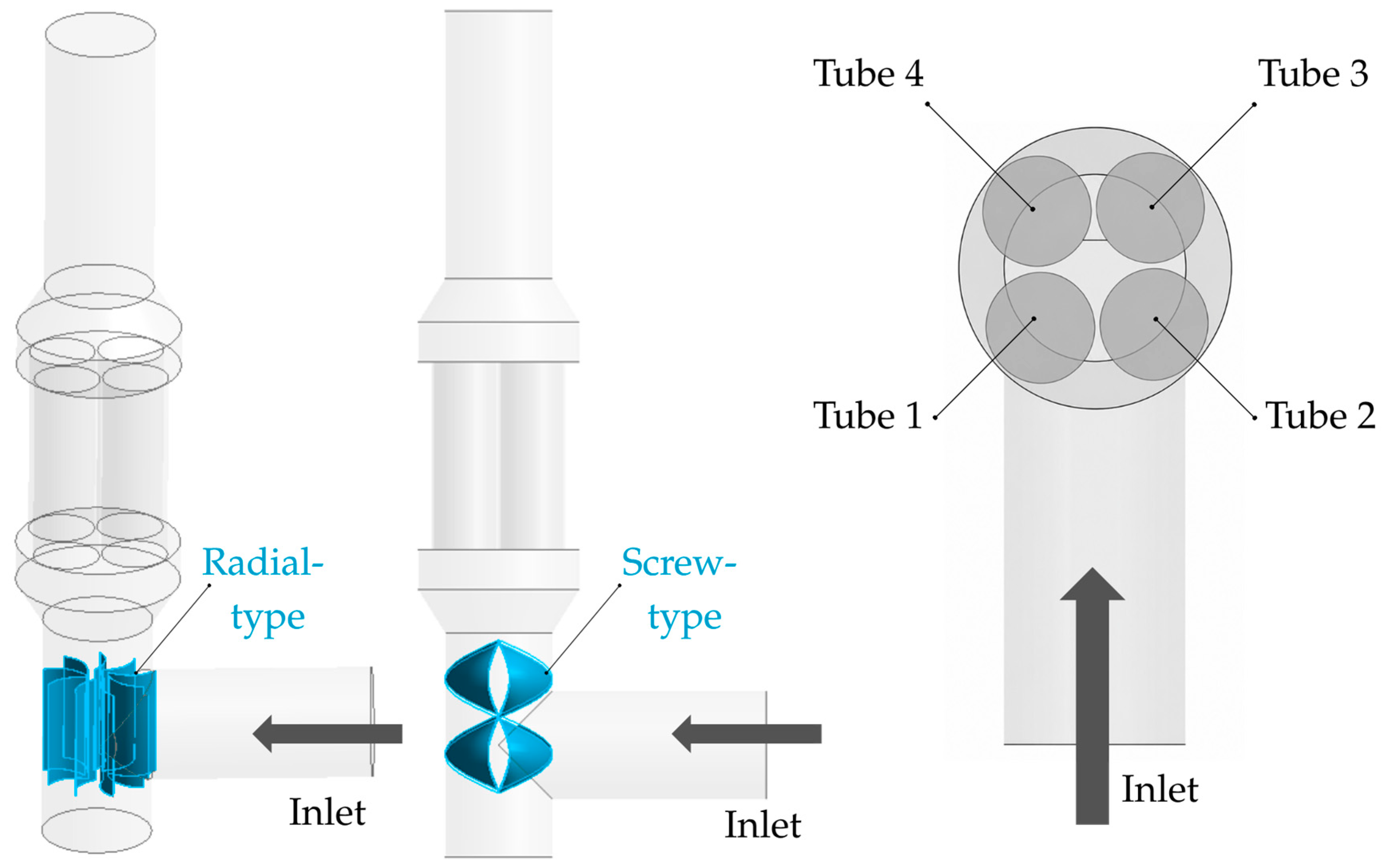
The CFD model of the four-tube ESP geometry was developed and solved in ANSYS Fluent 2024 R2. The standard tubular separator was modified to a four-tube configuration. The original 200 mm duct was enlarged to 300 mm, accommodating four parallel tubes with a diameter of 120 mm each. Flue gas was supplied from the side and passed sequentially through a T-junction, the enlarged duct, the four tubes, and a downstream reducer returning the diameter to 200 mm.
Based on the active collecting surfaces of the investigated geometries, the four-tube configuration provides an approximately 1.6-fold increase in collecting area compared with the original 200 mm tubular arrangement. Considering only the cylindrical collecting surface, the active collecting area of one tube was 0.132 m2, resulting in a total collecting area of 0.528 m2 for the four-tube configuration. In addition, the total cross-sectional flow area of the four 120 mm tubes is 1.44 times larger than that of the original 200 mm duct. However, the practical utilization of this enlarged collecting area depends on the uniformity of flue-gas redistribution among the four parallel tubes. Therefore, the present CFD analysis focuses on the effect of flow-guiding structures on tube-to-tube flow distribution and particle-transport behavior.
Additionally, nine radial inserts were incorporated into the four-tube separator to guide the flue-gas flow. With nine radial inserts added at the T-junction, the flow was assumed to be conditioned and redistributed as it entered the downstream sections. The screw-type flow-guiding structure was previously investigated [40] and was retained in the present study as a reference configuration for comparison with the basic geometry and the radial-insert design. The investigated guiding elements were selected with respect to the side-inlet arrangement of the ESP. In this geometry, the incoming flue gas enters the T-junction with lateral momentum, which can produce preferential flow paths and uneven distribution among the four tubes. The radial inserts were chosen as a simple passive vane-type concept for redirecting the inlet jet toward the central region, while the screw-type guide was included as a reference configuration capable of inducing controlled circumferential redistribution of the flow. Other passive flow-conditioning solutions reported for ESP or related duct-flow applications include perforated plates, turning or guide vanes, diffuser-mounted distribution elements, and, in more general duct-flow systems, honeycomb straighteners [21,22].
A simplified estimate of the collection efficiency () of tube i based on the Deutsch–Anderson equation was used:
where AC is the collecting area of one tube, Qi is the flow rate through the corresponding tube derived from the CFD-calculated average velocity, and we is the effective particle migration velocity. Because parameter we was not measured, it was selected parametrically to represent a nominal collection efficiency of 80% under ideally uniform flow conditions. The corresponding value for we was 0.144 m s−1. The overall efficiency was calculated as the flow-weighted average of the four tubes.
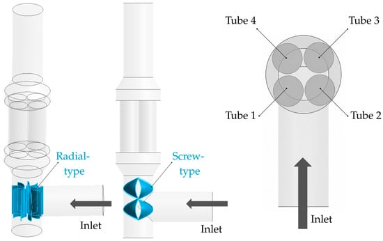
Figure 1 shows the design of the radial- and screw-type flow-guiding elements. The right-hand side of the figure also indicates the numbering of the individual tubes used for the evaluation of tube-averaged velocities.
Figure 1.
Four-tube ESP design with radial-type and screw-type flow-guiding elements.
The generated meshes were predominantly tetrahedral for all investigated geometries. Local mesh refinement was applied in the T-junction, in the vicinity of the radial and screw-type guiding structures, and in the transition regions between the enlarged duct and the four parallel tubes. Inflation layers were generated near solid walls to improve the resolution of near-wall velocity gradients. The basic model contained 340,729 elements, whereas the models with radial and screw constructions required substantially finer meshes, with 374,612 and 375,175 elements, respectively. The average orthogonal quality remained high in all cases, ranging from 0.763 to 0.771, while the average skewness values were low, between 0.228 and 0.235. The mesh quality stated in Table 1 for all models was considered acceptable based on the established criteria.
Table 1.
Mesh quality.
A mesh-independence assessment (Table 2) was performed for the screw-type guide configuration, which represents the most geometrically complex investigated case. Three mesh levels were generated: coarse, medium, and fine. The comparison was based on the pressure drop, the tube-averaged velocities, the maximum-to-minimum velocity ratio, and the coefficient of variation of the four tube-averaged velocities. These quantities were selected because they represent the main numerical indicators used to evaluate flow redistribution in the present study. The pressure drop was calculated as the difference between the area-weighted average static pressure at the inlet and outlet planes.
Table 2.
The mesh-independence study.
The mesh-independence assessment showed that the medium and fine meshes provided similar results for the screw-type guide configuration. The pressure drop differed by approximately 2.5%, while the mean of the four tube-averaged velocities differed by less than 1%. The maximum-to-minimum velocity ratio and the coefficient of variation also remained close, with differences of approximately 2–3%. Therefore, the medium mesh was considered sufficient for comparative aerodynamic analysis.
The simulations were performed under steady-state conditions using two boundary conditions: an inlet mass flow rate and an outlet pressure. The inlet was defined as a mass-flow inlet with a mass flow rate of 0.0356 kg·s−1. This value was derived from anemometer measurements performed in an 80 mm diameter duct at a gas temperature of approximately 27 °C. The measured velocity was converted to mass flow rate using Equation (2).
where ρ is the fluid density, A is the cross-sectional area of the inlet duct, and is the measured mean flue-gas velocity. In the CFD model, the same mass flow rate was prescribed at the 200 mm inlet section. Because the energy equation was not solved, heat transfer and temperature variations within the gas phase were not considered, the corresponding gas density was 0.756 kg·m−3, and the prescribed mass flow rate corresponds to an average inlet velocity of approximately 1.5 m·s−1. The same inlet mass flow rate and outlet pressure were applied to all investigated geometries to ensure a consistent comparison of the flow redistribution caused by the internal guiding elements.
The outlet boundary was defined as a pressure outlet with a gauge static pressure of −12 Pa. This value represents the chimney draught in the flue-gas path of a small-scale combustion appliance and is consistent with the operating conditions considered according to STN EN 13240 [41].
Euler–Lagrange approach was applied, in which the continuous gas phase was solved in the Eulerian framework and the entrained ash particles were tracked using the Lagrangian discrete-phase formulation. The airflow was computed from the Navier–Stokes equations, whereas the motion of particles was resolved by Lagrangian particle tracking. The particle trajectories were obtained by integrating the governing force balance, in which particle inertia is balanced by the forces acting on the particle, according to Equation (3).
where Fx means an additional acceleration, FD presents the drag force per unit particle mass, u is the fluid velocity, up is the particle velocity and ρp is the particle density [42].
The governing equations were solved using a pressure-based steady-state solver. Pressure–velocity coupling was handled using the coupled algorithm.
One-way coupling was applied in the discrete phase model. The total particle mass flow rate and the particle-size-distribution input for the DPM model were derived from gravimetric measurements of total suspended particles performed under the same operating conditions using a three-stage impactor. Based on these measurements, the total particle mass flow rate was set to 8.4 × 10⁻⁷ kg·s−1. Since the gas-phase mass flow rate was 0.0356 kg·s−1, the resulting particle-to-gas mass loading ratio was approximately 2.4 × 10⁻⁵. Therefore, the feedback of the dispersed phase on the continuous gas phase was neglected.
Particles were injected from the inlet surface with an initial velocity of 1.5 m·s−1, corresponding to the average gas velocity calculated for the 200 mm CFD inlet section at the prescribed mass flow rate and simulated flue-gas temperature. The particles were treated as inert entrained ash (PM particles) transported by the flue gas during small-scale solid-fuel combustion. The particle density was set to 2000 kg·m−3. The particle size distribution was described using the Rosin–Rammler function with a minimum diameter of 1.0 × 10⁻⁷ m, maximum diameter of 5.0 × 10⁻⁵ m, mean diameter of 2.1 × 10⁻⁷ m, spread parameter of 0.19, and three discrete diameter classes. These Rosin–Rammler parameters were obtained from the gravimetric particle fractions measured by the three-stage impactor. The morphological, chemical, and mineralogical characterization of the particles was outside the scope of the present numerical study. The SST k-ω model was employed to account for turbulence. The tracked particles represent entrained ash (PM particles) transported by the flue gas during small-scale solid-fuel combustion. In the present CFD model, they were used to evaluate the redistribution of particle-laden flow among the four tubes. Therefore, the particles were described by density and size distribution, which are the input parameters required for Lagrangian particle tracking. The model did not include morphological, chemical, or mineralogical characterization of the particles.
The tube-averaged velocities were evaluated as volume-average gas velocities on cross-sectional planes. Flow uniformity was quantified using the maximum-to-minimum velocity ratio and the coefficient of variation of the four tube-averaged velocities.
Although the investigated geometry corresponds to an electrostatic precipitator, the present numerical model was aimed at the aerodynamic redistribution of flue gas and the Lagrangian transport behavior of entrained ash particles. The electric field, corona discharge, particle charging, Coulomb force, electrostatic migration, and particle deposition on the collecting electrodes were not resolved. Therefore, the model does not directly predict PM collection efficiency. Instead, it provides aerodynamic and particle-transport indicators that describe how effectively the enlarged collecting area of the four-tube ESP can be utilized.
3. Results
The numerical simulations were used to evaluate how the internal flow-guiding elements affect the distribution of flue gas within the four-tube electrostatic precipitator. Although the four-tube arrangement provides a larger collecting surface than a conventional tubular configuration, its effective use depends on whether the particle-laden flue gas is distributed uniformly among the individual tubes. Therefore, the basic geometry without a flow-guiding element was compared with two modified configurations: one equipped with nine radial inserts and the other with a screw-type guiding structure positioned in the T-junction space.
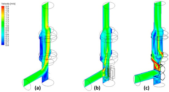
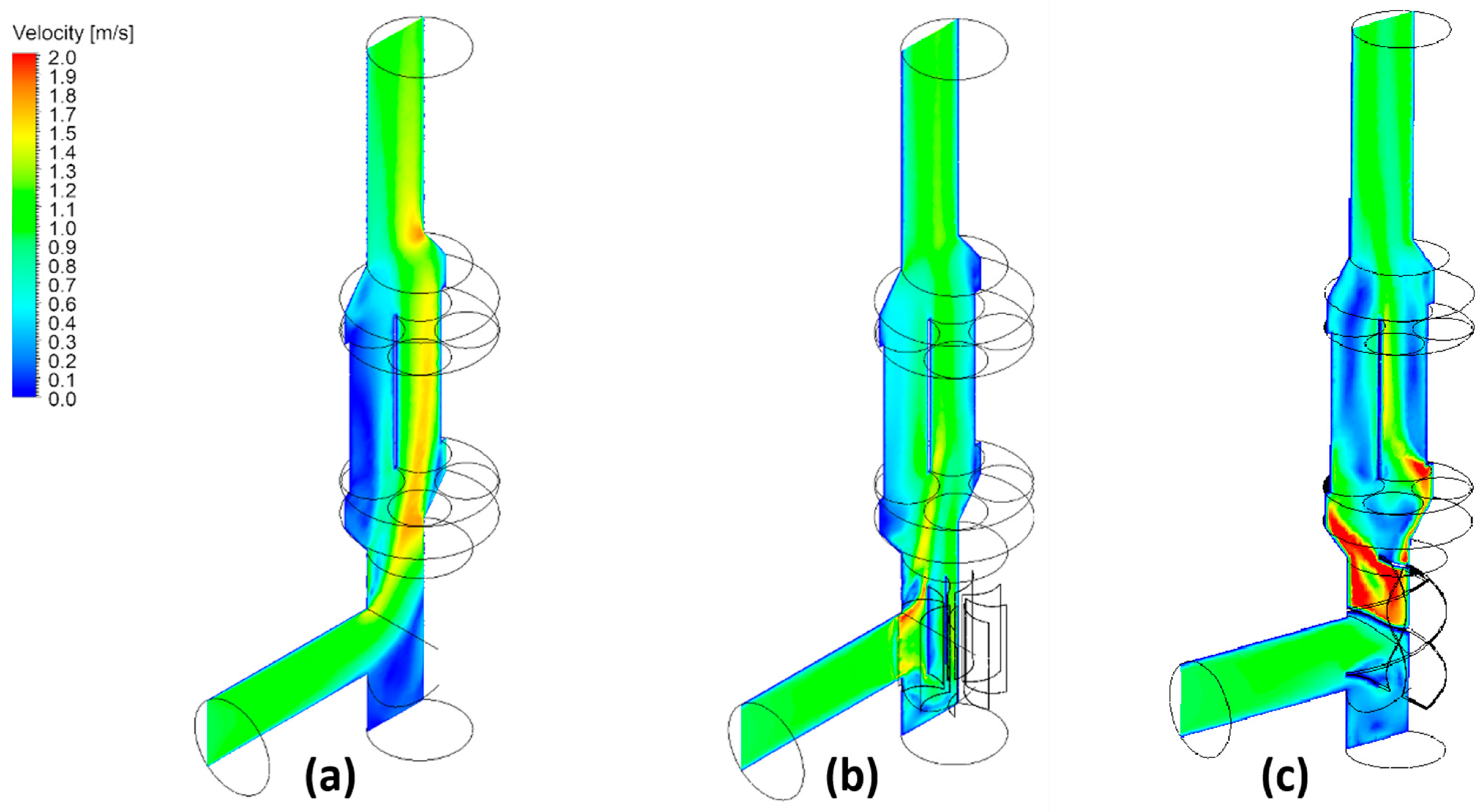
The velocity distribution in Figure 2 shows clear differences among the three investigated geometries. In the basic configuration, the incoming flue gas was not evenly redistributed after entering the enlarged section. The flow preferentially passed through two of the four tubes, while the remaining tubes were only weakly supplied. This behavior indicates a pronounced flow maldistribution caused by the side inlet and the subsequent expansion into the four-tube section. Such an uneven flow field may reduce the effective use of the available collecting surface because the residence time and particle loading are not balanced across the separator.
Figure 2.
Velocity distribution of ESP with (a) basic configuration, (b) radial-type construction, and (c) screw-type construction.
Using the radial inserts modified the flow distribution and reduced the asymmetry observed in the basic geometry. The inserts acted as passive flow-distribution elements, redirecting part of the incoming gas toward the less-utilized tubes. As a result, the velocity field became more balanced across the four outlets. Nevertheless, some non-uniformity remained.
The screw-type construction produced a further redistribution of the gas flow. The highest local velocities occurred in the region where the flue gas passed through the screw guide, which is consistent with the local flow acceleration induced by the guiding geometry. Downstream of this region, however, the flow was distributed more evenly among the four tubes than in the basic model. This indicates that the screw-type element not only changes the local velocity field but also supports a more effective transfer of the incoming flow into the parallel tube arrangement.
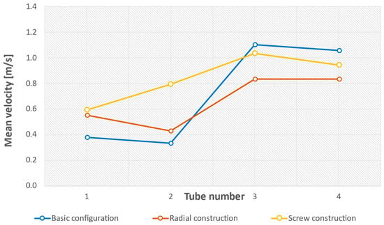
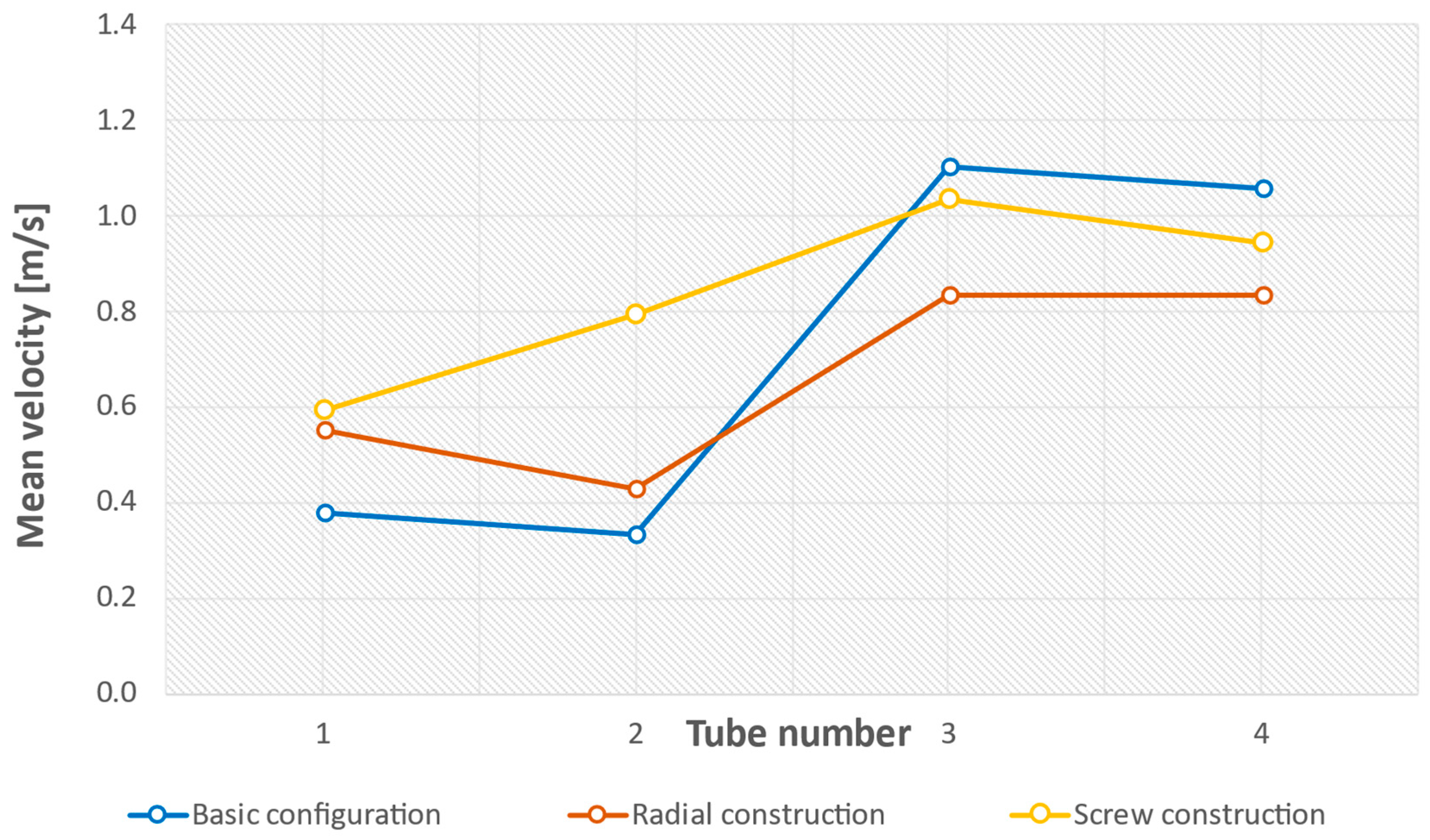
The differences between the three geometries are also evident from the tube-averaged velocities shown in Figure 3. The tube-averaged velocities in the basic configuration were 0.38, 0.33, 1.10, and 1.05 m·s−1 in tubes 1–4, respectively. Thus, most of the gas flow was concentrated in two tubes, while the other two tubes were poorly utilized. The ratio between the highest and lowest mean velocity was 3.31, confirming the strong imbalance of the basic configuration.
Figure 3.
Mean velocities of individual pipes in ESP with basic configuration, radial and screw constructions.
After adding the radial inserts, the mean velocities became 0.55 m·s−1, 0.43 m·s−1, 0.83 m·s−1, and 0.84 m·s−1 in tubes 1–4, respectively. Compared with the basic model, the spread between the highest and lowest tube velocity decreased from 0.77 m·s−1 to 0.41 m·s−1. The corresponding max/min velocity ratio was reduced to 1.95. This demonstrates that the radial inserts substantially improved the flow distribution, although tubes 3 and 4 still carried somewhat higher velocities than tubes 1 and 2.
For the screw-guided geometry, the mean velocities in tubes 1–4 were 0.59 m·s−1, 0.79 m·s−1, 1.03 m·s−1, and 0.94 m·s−1, respectively. In this case, the maximum-to-minimum velocity ratio decreased further to 1.75. The coefficient of variation calculated from the tube-averaged velocities decreased from approximately 51% in the model without flow guidance to 27% for the radial-insert geometry and to 20% for the screw-guided geometry. The coefficient of variation was calculated as the population standard deviation divided by the arithmetic mean of the four tube-averaged velocities. Based on this criterion, the screw-type structure provided a more uniform redistribution of the gas flow among the four tubes.
The simplified Deutsch–Anderson estimate resulted in an overall collection efficiency of 73.2% for the basic configuration, 78.1% for the radial-insert configuration, and 78.9% for the screw-type guide. The screw-type guide therefore provided an estimated improvement of 5.7 percentage points relative to the basic configuration and 0.8 percentage points relative to the radial-insert configuration.
The pressure drop was also evaluated for the three investigated configurations using the medium mesh. The basic model showed the lowest pressure drop of 1.55 Pa. The radial-insert configuration increased the pressure drop to 2.43 Pa, while the screw-type guide resulted in the highest-pressure drop of 4.06 Pa. Thus, the improved flow redistribution obtained with the guiding elements was accompanied by an increase in hydraulic resistance. However, the absolute pressure-drop values remained low under the investigated operating conditions.
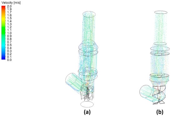
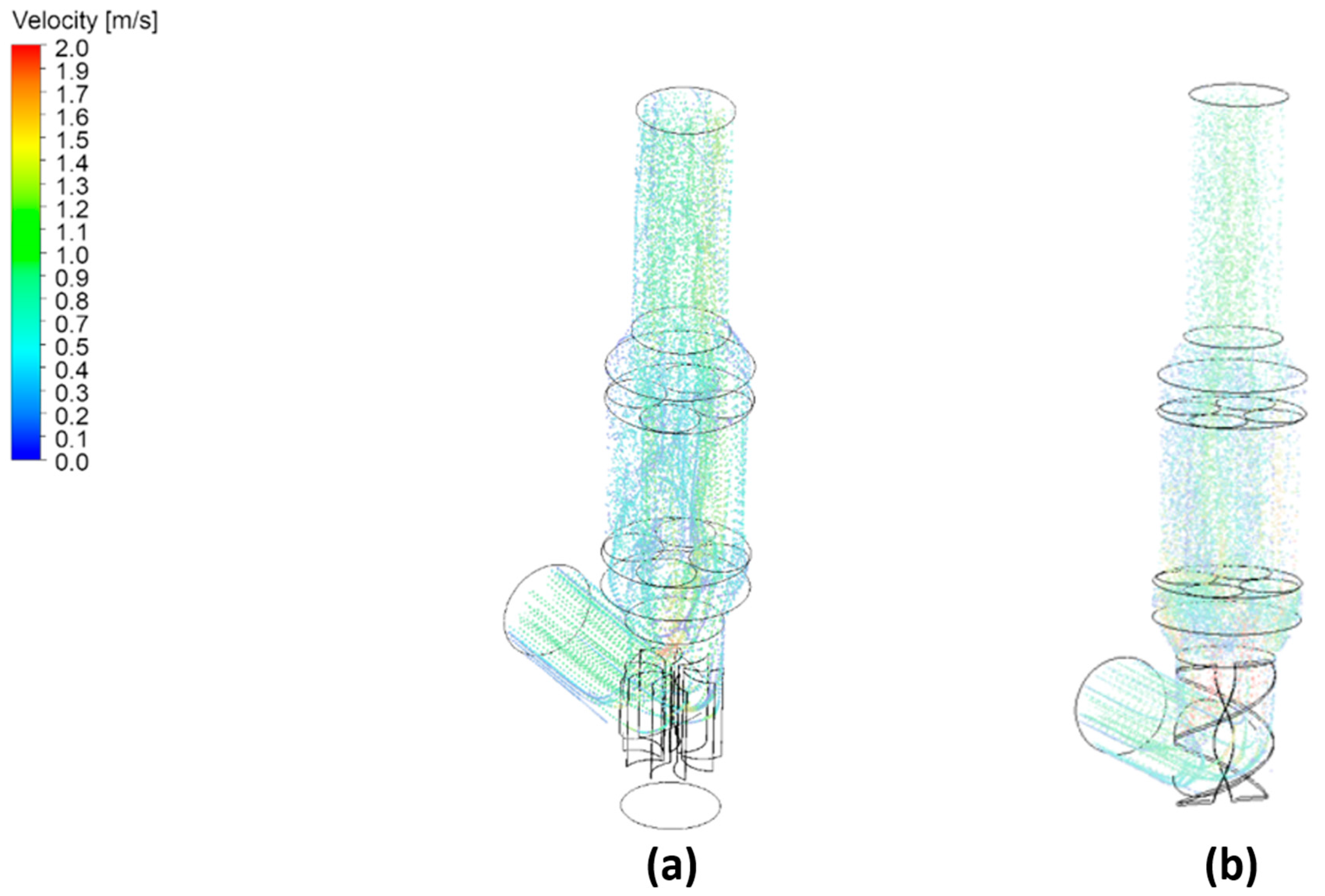
The particle velocity field for the radial and screw-guided model is shown in Figure 4. Since the particles were solved using Lagrangian tracking within the carrier-gas flow, their motion followed the main features of the gas-phase velocity field. Higher particle velocities were observed near the radial or screw construction, where the gas flow was locally accelerated. After passing this region, the particle trajectories were more evenly directed toward the four parallel tubes.
Figure 4.
Particle velocities of ESP with (a) radial-type construction, and (b) screw-type construction.
Overall, both investigated flow-guiding concepts reduced the maldistribution found in the basic four-tube ESP. The radial inserts provided an improvement by redirecting the flow toward the under-supplied tubes. However, the screw-type construction showed a more balanced tube-to-tube velocity distribution. These results confirm that the aerodynamic design of the inlet and transition region is essential for the effective operation of a multi-tube electrostatic precipitator, especially when the objective is to use the increased collecting area as uniformly as possible.
4. Discussion
The present CFD results demonstrate that the design of the inlet and transition region is an important factor for the effective operation of a four-tube electrostatic precipitator. Although the four-tube configuration increases the available collecting area compared with a conventional tubular ESP, this geometrical advantage can be fully utilized only if the PM-laden flue gas is distributed relatively evenly among the individual tubes. In the basic configuration without flow guidance, the side inlet and the subsequent expansion into the larger separator body caused an asymmetric flow pattern.
This finding is consistent with previous CFD-based studies on ESPs, which have emphasized that non-uniform gas distribution reduces the effective collection volume and may decrease the practical benefit of increasing the collecting area. Drga et al. [16] similarly showed that increasing the collecting surface in a tubular ESP intended for small heat sources must be accompanied by an assessment of gas velocity and pressure drop. In their study, CFD was used to evaluate how structural elements dividing the precipitation space influence the flow field. The importance of geometrical optimization is also supported by Holubčík et al. [30], who investigated a multi-chamber ESP for small heat sources and demonstrated that both the collecting area and the arrangement of the discharge electrodes affect the predicted PM capture. Their results showed that dividing the precipitation space into multiple chambers can improve the theoretical separation potential, but the final performance remains sensitive to the distribution of particles in the flowing gas.
The numerical comparison showed that both investigated flow-guiding concepts improved the tube-to-tube velocity distribution in this study. The improvement obtained with passive flow-guiding elements agrees with the general conclusions of studies focused on flow-field optimization in ESPs. Ye et al. [43] used multi-scale CFD simulations for a wet ESP and showed that optimization of the inlet and internal flow-control elements can make the velocity distribution more uniform and balance the flow rate between different electric-field regions. Similarly, Haque et al. [44] investigated gas-flow simulation in a thermal power plant ESP and identified the inlet-flow pattern as a key factor affecting the internal velocity distribution. Although these studies were performed for larger industrial ESPs, physical interpretation can be transferable to compact separators.
The present results should be interpreted primarily from the viewpoint of aerodynamic flow redistribution. From a practical design perspective, the screw-type guide provided the most uniform flow redistribution, but it is also more geometrically complex than the radial inserts. Its implementation may require more careful manufacturing, positioning, and mechanical fixation, and its influence on ash deposition and cleaning accessibility should be considered. Therefore, the final design should balance flow uniformity, pressure drop, manufacturing simplicity, and maintenance requirements. In real operation, the performance of a compact ESP is also affected by processes that were not resolved in the present CFD model, including ash deposition on internal surfaces, gradual fouling of the flow-guiding elements, cleaning requirements, thermal loading, and possible changes in surface conditions during long-term operation. These effects may influence the local flow field and the practical availability of the collecting surfaces, particularly in geometries with additional internal structures. Therefore, the investigated guiding concepts should be considered as aerodynamic design variants whose long-term operational behavior requires experimental verification under real combustion conditions.
The relevance of residence time and gas velocity is well established in ESP literature. Kılıç et al. [45] showed that the inlet velocity, electrode spacing, wire diameter and applied voltage all influence particle collection efficiency in a wire-plate ESP. Lin et al. [46] reported increased particle penetration at higher flow rates, which they attributed to the shorter residence time available for particle charging and migration. These findings support the interpretation that the more uniform velocity field obtained in the present study is favorable for ESP operation. In the four-tube geometry, this effect is related not only to the average gas velocity but also to the distribution of flow among the parallel tubes. If a large fraction of the gas passes through only one or two tubes, these regions operate with shorter residence times and higher local particle loading, while the remaining collecting surfaces are underutilized. A more uniform tube-to-tube flow distribution can therefore improve the aerodynamic precondition for particle charging, electrostatic migration, and deposition by reducing locally overloaded high-velocity paths and supplying the particle-laden gas more evenly to the available collecting area. Compared with the basic model, both flow-guiding configurations reduced this maldistribution and improved the aerodynamic utilization of the four-tube collecting section.
The practical relevance of flow conditioning is supported by a study by Čajová Kantová et al. [39], which involved CFD and experimental work on an ESP connected to a pellet boiler, where the implementation of a flow straightener improved the flow field and increased the measured collection efficiency. In that study, the configuration without a straightener reached a collection efficiency of 90.76%, whereas the partially inserted flow straightener achieved 93.09%. This indicates that flow redistribution can influence real ESP performance, although the magnitude of this effect depends on the electric field, particle charging, deposition behavior, and operating conditions.
The pressure drop increased from 1.55 Pa in the basic model to 2.43 Pa for the radial inserts and 4.06 Pa for the screw-type guide. Although the relative increase is noticeable, the absolute pressure drop remained low under the investigated operating conditions. Therefore, the screw-type guide appears favorable from the viewpoint of flow redistribution, but its final practical application should also consider pressure drop, manufacturing complexity, ash deposition, and cleaning accessibility.
The Lagrangian particle-tracking approach used in the present work is also consistent with previous numerical studies on ESPs. Skodras et al. [47] and Nikas et al. [48] applied CFD-based models to describe the coupled behavior of gas flow, particle motion and electrostatic precipitation. More recent work by Shen et al. [49] also emphasized that the Lagrangian approach is suitable for diluting particle-laden ESP flows because it allows particle trajectories to be followed until collection or escape.
The present results are also compatible with experimental studies on small-scale ESPs connected to biomass combustion appliances. Cid et al. [25] tested an attachable ESP downstream of a pellet boiler and reported that separation performance depends on supplied voltage, particle size and discharge electrode geometry, with efficiencies approaching 90% under favorable operating conditions. Vicente et al. [24] showed that ESP performance in residential biomass appliances can vary depending on the combustion system and operating conditions. Čajová Kantová et al. [50] experimentally evaluated a four-tube ESP downstream of an automatic pellet boiler and found that collection efficiencies above 80% were achievable across different fan settings, with the best performance occurring at moderate airflow. These studies indicate that small-scale ESPs can substantially reduce PM emissions, but they also confirm that gas-flow rate and internal geometry strongly influence the achieved performance.
Unlike these experimental studies, the present study does not experimentally determine or directly simulate PM collection efficiency. It provides only a simplified parametric estimate based on the calculated flow distribution. A key limitation is that the model does not include electric-field effects. Although the investigated device is an ESP, the simulations were restricted to gas-flow redistribution and Lagrangian particle transport. Corona discharge, particle charging, Coulomb forces, electrostatic migration, and particle deposition on the collecting electrodes were not resolved. Therefore, the results cannot be interpreted as PM collection-efficiency predictions. Instead, they should be understood as aerodynamic indicators showing how uniformly the particle-laden gas is supplied to the four collecting tubes. From this viewpoint, the results provide a hydrodynamic explanation of why a four-tube ESP may require flow-guiding elements to utilize the enlarged collecting area more effectively. A quantitative prediction of ESP performance would require a coupled electrohydrodynamic model including gas flow, electric-field distribution, particle charging, and deposition.
5. Conclusions
This study numerically investigated the influence of two flow-guiding concepts on the flue-gas distribution inside a four-tube electrostatic precipitator intended for PM reduction from small-scale combustion systems. Three geometries were compared: a basic four-tube configuration without flow guidance, a configuration equipped with radial inserts, and a configuration with a screw-type guiding structure located in the T-junction region. The simulations were performed using CFD, while the particle phase was evaluated by Lagrangian particle tracking.
The results showed that the basic four-tube geometry exhibited a pronounced non-uniform flow distribution. Most of the flue gas was directed through tubes 3 and 4, whereas tubes 1 and 2 were only weakly supplied. The maximum-to-minimum mean velocity ratio reached 3.31, and the coefficient of variation of the tube-averaged velocities was approximately 51%. This confirms that increasing the collecting area by dividing the separator into four tubes does not automatically ensure effective use of the available collecting surface.
Both investigated flow-guiding structures improved the redistribution of the flue gas among the four tubes. The radial inserts reduced the maximum-to-minimum velocity ratio to 1.95 and decreased the coefficient of variation to approximately 27%. However, the screw-type construction provided more uniform flow distribution, with a maximum-to-minimum velocity ratio of 1.75 and a coefficient of variation of approximately 20%.
The particle velocity fields confirmed that the motion of entrained particles followed the main features of the carrier-gas flow. Local acceleration occurred near the radial and screw guiding elements, but downstream of these structures, the particle-laden flow was distributed more evenly toward the four parallel tubes. This behavior is favorable for ESP operation because a more homogeneous particle supply can support better utilization of the enlarged collecting area.
Overall, the results demonstrate that inlet-flow conditioning is essential for the practical application of a four-tube ESP. Without a suitable flow-guiding element, the enlarged geometry may be only partially utilized due to flow maldistribution. Among the tested designs, the screw-type construction provided the most balanced tube-to-tube velocity distribution and therefore appears to be the most promising option for further development. Future work should include electric-field modelling, particle charging and deposition, and experimental validation under real combustion conditions to quantify the actual PM collection efficiency of the proposed design. Such validation should include velocity measurements in the individual tubes, cleaning requirements, and long-term flow stability during operation.
Author Contributions
N.Č.K., conceptualization, writing—original draft preparation, funding acquisition; A.B., methodology, writing—review and editing, data curation; J.D., investigation, resources, validation; A.Č. visualization, software, formal analysis. All authors have read and agreed to the published version of the manuscript.
Funding
This publication has been produced with the support of VEGA No. 1/0311/26: Autonomous control of the combustion process in small heat sources using artificial intelligence and KEGA No. 035ŽU-4/2024: Ventilation and air conditioning systems for clean rooms.
Data Availability Statement
Data are contained within the article.
Acknowledgments
During the preparation of this manuscript, the authors used OpenAI ChatGPT (GPT-5.6 Sol) for language editing, improvement of clarity, and assistance with structuring selected parts of the manuscript. The authors reviewed and edited all AI-assisted text. No AI tool was used to generate experimental data, modify figures, perform measurements, or create references.
Conflicts of Interest
The authors declare no conflicts of interest. The funders had no role in the design of the study; in the collection, analyses, or interpretation of data; in the writing of the manuscript; or in the decision to publish the results.
Abbreviations
| AC | Collecting area of one tube |
| CFD | Computational fluid dynamics |
| CV | Coefficient of variation |
| DEM | Discrete element method |
| ESP | Electrostatic precipitator |
| PIV | Particle image velocimetry |
| PM | Particulate matter |
| Qi | Flow rate through the corresponding tube |
| u | Velocity |
| we | Effective particle migration velocity |
| Δp | Pressure drop |
| Collection efficiency of tube i |
References
- Singh, K.; Tripathi, D. Particulate Matter and Human Health. In Environmental Health; IntechOpen: London, UK, 2021. [Google Scholar] [CrossRef] [Scilit]
- Elbl, P.; Sitek, T.; Lachman, J.; Lisý, M.; Baláš, M.; Pospíšil, J. Sewage Sludge and Wood Sawdust Co-Firing: Gaseous Emissions and Particulate Matter Size Distribution. Energy 2022, 256, 124680. [Google Scholar] [CrossRef] [Scilit]
- Rimar, M.; Kizek, J.; Kulikov, A.; Fedak, M. Study of selected burner parameters on the gas-air mixture combustion. MM Sci. J. 2022, 2022, 6251–6256. [Google Scholar] [CrossRef] [Scilit]
- Taušová, M.; Mykhei, M.; Čulkova, K.; Tauš, P.; Petráš, D.; Kaňuch, P. Development of the Implementation of Renewable Sources in EU Countries in Heating and Cooling, Transport, and Electricity. Sustainability 2025, 17, 766. [Google Scholar] [CrossRef] [Scilit]
- Mizuno, A. Electrostatic Precipitation. IEEE Trans. Dielectr. Electr. Insul. 2000, 7, 615–624. [Google Scholar] [CrossRef] [Scilit]
- De Oliveira, A.E.; Guerra, V.G. Electrostatic precipitation of nanoparticles and submicron particles: Review of technological strategies. Process Saf. Environ. Prot. 2021, 153, 422–438. [Google Scholar] [CrossRef] [Scilit]
- Ozgen, S. Methods for particulate matter emission reduction from pellet boilers. Biomass Convers. Biorefinery 2024, 14, 8189–8213. [Google Scholar] [CrossRef] [Scilit]
- Lim, M.T.; Phan, A.; Roddy, D.; Harvey, A. Technologies for Measurement and Mitigation of Particulate Emissions from Domestic Combustion of Biomass: A Review. Renew. Sustain. Energy Rev. 2015, 49, 574–584. [Google Scholar] [CrossRef] [Scilit]
- Jaworek, A.; Sobczyk, A.T.; Marchewicz, A.; Krupa, A.; Czech, T. Particulate Matter Emission Control from Small Residential Boilers after Biomass Combustion. A Review. Renew. Sustain. Energy Rev. 2021, 137, 110446. [Google Scholar] [CrossRef] [Scilit]
- Jaworek, A.; Krupa, A.; Czech, T. Modern Electrostatic Devices and Methods for Exhaust Gas Cleaning: A Brief Review. J. Electrostat. 2007, 65, 133–155. [Google Scholar] [CrossRef] [Scilit]
- Høgh Petersen, H. Performance of electrostatic precipitators. Inciner. Munic. Waste 1988, 4, 21–31. [Google Scholar] [CrossRef] [Scilit]
- Molchanov, O.; Krpec, K.; Horák, J. Electrostatic Precipitation as a Method to Control the Emissions of Particulate Matter from Small-Scale Combustion Units. J. Clean. Prod. 2020, 246, 119022. [Google Scholar] [CrossRef] [Scilit]
- Arif, S.; Branken, D.J.; Everson, R.C.; Neomagus, H.W.J.P.; le Grange, L.A.; Arif, A. CFD Modeling of Particle Charging and Collection in Electrostatic Precipitators. J. Electrostat. 2016, 84, 10–22. [Google Scholar] [CrossRef] [Scilit]
- Guo, B.; Yu, A.; Guo, J. Numerical Modelling of ESP for Design Optimization. Procedia Eng. 2015, 102, 1366–1372. [Google Scholar] [CrossRef] [Scilit]
- Li, S.; Huang, Y.; Zheng, Q.; Deng, G.; Yan, K. A Numerical Model for Predicting Particle Collection Efficiency of Electrostatic Precipitators. Powder Technol. 2019, 347, 170–178. [Google Scholar] [CrossRef] [Scilit]
- Drga, J.; Holubčík, M.; Čajová Kantová, N.; Červenka, B. Design of a Low-Cost Electrostatic Precipitator to Reduce Particulate Matter Emissions from Small Heat Sources. Energies 2022, 15, 4148. [Google Scholar] [CrossRef] [Scilit]
- Buczyński, R.; Weber, R.; Szlęk, A. Innovative Design Solutions for Small-Scale Domestic Boilers: Combustion Improvements Using a CFD-Based Mathematical Model. J. Energy Inst. 2015, 88, 53–63. [Google Scholar] [CrossRef] [Scilit]
- Kantová, N.Č.; Čaja, A.; Patsch, M.; Holubčík, M.; Ďurčanský, P. Dependence of the Flue Gas Flow on the Setting of the Separation Baffle in the Flue Gas Tract. Appl. Sci. 2021, 11, 2961. [Google Scholar] [CrossRef] [Scilit]
- Wang, Y.; Peng, H.; Yin, Z.; Bao, F.; Hou, L. Deposition characteristics of ultrafine particles of different shapes in an inertial impactor: CFD-DEM simulations and experiments. Exp. Comput. Multiph. Flow 2025, 7, 284–296. [Google Scholar] [CrossRef] [Scilit]
- Bhasker, C. Flow simulation in Electro-Static-Precipitator (ESP) ducts with turning vanes. Adv. Eng. Softw. 2011, 42, 501–512. [Google Scholar] [CrossRef] [Scilit]
- Ye, X.-L.; Su, Y.-B.; Guo, B.-Y.; Yu, A.-B. Multi-scale simulation of the gas flow through electrostatic precipitators. Appl. Math. Model. 2016, 40, 9514–9526. [Google Scholar] [CrossRef] [Scilit]
- Kim, D.U.; Kim, J.T.; Jeong, S.H.; Lee, S.S. Structure and arrangement of perforated plates for uniform flow distribution in an electrostatic precipitator. J. Air Waste Manag. Assoc. 2021, 71, 328–338. [Google Scholar] [CrossRef] [Scilit] [PubMed]
- Marković, Z.J.; Erić, M.D.; Stefanović, P.L.; Jovanović, R.D.; Lazović, I.M. Optimi-zation of the flue gas-flow controlling devices of the electrostatic precipitator of Unit A4 in TPP “Nikola Tesla”. Therm. Sci. 2023, 27, 3591–3606. [Google Scholar] [CrossRef] [Scilit]
- Vicente, E.D.; Duarte, M.A.; Tarelho, L.A.C.; Alves, C.A. Efficiency of Emission Reduction Technologies for Residential Biomass Combustion Appli-ances: Electrostatic Precipitator and Catalyst. Energies 2022, 15, 4066. [Google Scholar] [CrossRef] [Scilit]
- Cid, N.; Patiño, D.; Pérez-Orozco, R.; Porteiro, J. Performance Analysis of a Small-Scale Electrostatic Precipitator with Biomass Combustion. Biomass Bioenergy 2022, 162, 106500. [Google Scholar] [CrossRef] [Scilit]
- Trnka, J.; Jandačka, J.; Holubčík, M. Improvement of the Standard Chimney Electrostatic Precipitator by Dividing the Flue Gas Stream into a Larger Number of Pipes. Appl. Sci. 2022, 12, 2659. [Google Scholar] [CrossRef] [Scilit]
- Holubčík, M.; Kantová, N.Č.; Trnka, J.; Jandačka, J. Decreasing Solid Aerosols from Small Heat Sources Using the Optimized Electrostatic Precipitator. Atmosphere 2022, 13, 1438. [Google Scholar] [CrossRef] [Scilit]
- Carroll, J.; Finnan, J. Use of Electrostatic Precipitators in Small-Scale Bio-mass Furnaces to Reduce Particulate Emissions from a Range of Feedstocks. Biosyst. Eng. 2017, 163, 94–102. [Google Scholar] [CrossRef] [Scilit]
- Brunner, T.; Wuercher, G.; Obernberger, I. 2-Year Field Operation Monitoring of Electrostatic Precipitators for Residential Wood Heating Systems. Biomass Bioenergy 2018, 111, 278–287. [Google Scholar] [CrossRef] [Scilit]
- Holubčík, M.; Drga, J.; Čajová Kantová, N.; Najser, J.; Frantík, J. Optimization of Discharging Electrodes of a Multi-Chamber Electrostatic Precipitator for Small Heat Sources. Atmosphere 2023, 14, 63. [Google Scholar] [CrossRef] [Scilit]
- Cid, N.; Chapela, S.; Gómez, M.Á.; Patiño, D. Growth Analysis of the Particle Layer in a Small-Scale ESP with Biomass Combustion. J. Electrostat. 2024, 127, 103881. [Google Scholar] [CrossRef] [Scilit]
- Holubcik, M.; Nemec, P.; Kapjor, A.; Kantova, N.C. Investigation of a Multi-Tube ESP: CFD-Based Electric Field and Efficiency Decrease During Long-Term Operation. IEEE Access 2025, 13, 147397–147407. [Google Scholar] [CrossRef] [Scilit]
- Lima, F.d.A.; Medeiros, G.B.; Chagas, P.A.M.; Aguiar, M.L.; Guerra, V.G. Aerosol Nanoparticle Control by Electrostatic Precipitation and Filtration Processes—A Review. Powders 2023, 2, 259–298. [Google Scholar] [CrossRef] [Scilit]
- Alt, B.; Klüh, D.; Gaderer, M. Development of an Online Monitoring Method for Electrostatic Precipitators on Commercial Biomass Combustion Plants. Biomass Convers. Biorefinery 2021, 11, 1965–1975. [Google Scholar] [CrossRef] [Scilit]
- Badran, M.; Mansour, A.M. Evaluating Performance Indices of Electrostatic Precipitators. Energies 2022, 15, 6647. [Google Scholar] [CrossRef] [Scilit]
- Schmatloch, V.; Rauch, S. Design and Characterisation of an Electrostatic Precipitator for Small Heating Appliances. J. Electrostat. 2005, 63, 85–100. [Google Scholar] [CrossRef] [Scilit]
- Jaworek, A.; Marchewicz, A.; Sobczyk, A.T.; Krupa, A.; Czech, T. Recent Advances in Electrostatic Precipitation of Particles from Flue Gases Generat-ed by Domestic Heating Appliances. A Brief Outlook. J. Electrostat. 2024, 129, 103922. [Google Scholar] [CrossRef] [Scilit]
- Kantová, N.Č.; Backa, A.; Čaja, A.; Jandačka, J. Effect of Fuel Feeding Cycle Adjustments on Emissions in Spruce Pellet Combustion with the Application of a Four-Tube Electrostatic Precipitator. Sci. Rep. 2025, 15, 25988. [Google Scholar] [CrossRef] [Scilit] [PubMed]
- Čajová Kantová, N.; Backa, A.; Čaja, A.; Sładek, S. Increasing Electrostatic Precipitator Efficiency by Implementing a Flow Straightener in the Flue Gas Pipe: CFD Simulations and Experimental Study. Case Stud. Therm. Eng. 2025, 73, 106737. [Google Scholar] [CrossRef] [Scilit]
- Čajová Kantová, N.; Backa, A.; Čaja, A.; Nemec, P. Flue gases flowing in the four-tubular electrostatic precipitator with an inserted screw construction based on CFD simulations. Procedia Struct. Integr. 2026, 77, 170–176. [Google Scholar] [CrossRef] [Scilit]
- STN EN 13240 (061206); Roomheaters Fired by Solid Fuel. Requirements and Test Methods. Slovak Office of Standards, Metrology and Testing (ÚNMS SR): Bratislava, Slovakia, 2002.
- Ansys Fluent Theory Guide. 2013. Available online: https://www.pmt.usp.br/ (accessed on 5 May 2026).
- Ye, X.-L.; Wang, S.; Zhang, H.; An, X.-Z.; Guo, B.-Y.; Li, L.-F. Process Simulation and Optimization of Flow Field in Wet Electrostatic Precipitator. J. Cent. South Univ. 2020, 27, 132–143. [Google Scholar] [CrossRef] [Scilit]
- Haque, S.M.E.; Rasul, M.G.; Deev, A.V.; Khan, M.M.K.; Subaschandar, N. Flow Simulation in an Electrostatic Precipitator of a Thermal Power Plant. Appl. Therm. Eng. 2009, 29, 2037–2042. [Google Scholar] [CrossRef] [Scilit]
- Kılıç, M.; Mutlu, M.; Altun, A.F. Numerical Simulation and Analytical Evaluation of the Collection Efficiency of the Particles in a Gas by the Wire-Plate Electro-static Precipitators. Appl. Sci. 2022, 12, 6401. [Google Scholar] [CrossRef] [Scilit]
- Lin, C.W.; Huang, S.H.; Kuo, Y.M.; Chang, K.N.; Wu, J.-S.; Chen, C.C. From electrostatic precipitation to nanoparticle generation. J. Aerosol Sci. 2012, 51, 57–65. [Google Scholar] [CrossRef] [Scilit]
- Skodras, G.; Kaldis, S.P.; Sofialidis, D.; Faltsi, O.; Grammelis, P.; Sakellaropoulos, G.P. Particulate Removal via Electrostatic Precipitators—CFD Simulation. Fuel Process. Technol. 2006, 87, 623–631. [Google Scholar] [CrossRef] [Scilit]
- Nikas, K.S.P.; Varonos, A.A.; Bergeles, G.C. Numerical Simulation of the Flow and the Collection Mechanisms inside a Laboratory Scale Electrostatic Precipitator. J. Electrost. 2005, 63, 423–443. [Google Scholar] [CrossRef] [Scilit]
- Shen, H.; Yu, W.; Wang, W.; Zheng, Y.; Kang, Y. Electrohydrodynamic Flow and Particle Behavior in Electrostatic Precipitators with Two Shaped Collecting Plates. Aerosol Air Qual. Res. 2025, 25, 33. [Google Scholar] [CrossRef] [Scilit]
- Kantová, N.Č.; Backa, A.; Cibula, R.; Belány, P. Operation of Four-Tube Electrostatic Precipitator during Pellet Combustion in Small-Scale Heat Source under Varying Inlet Air Mass Flow Rate. Biomass Convers. Biorefinery 2026, 16, 181. [Google Scholar] [CrossRef] [Scilit]

Disclaimer/Publisher’s Note: The statements, opinions and data contained in all publications are solely those of the individual author(s) and contributor(s) and not of MDPI and/or the editor(s). MDPI and/or the editor(s) disclaim responsibility for any injury to people or property resulting from any ideas, methods, instructions or products referred to in the content. |
© 2026 by the authors. Licensee MDPI, Basel, Switzerland. This article is an open access article distributed under the terms and conditions of the Creative Commons Attribution (CC BY) license.