


Abstract
To address the critical role of armature–rail contact in electromagnetic railguns, a comprehensive electromagnetic–thermal–mechanical coupled model is developed. In contrast to existing coupled railgun models, this work uniquely introduces the dynamic mechanical contact state and contact resistance as coupling variables and explicitly accounts for the interference−fit process during armature loading, enabling a full−cycle simulation from assembly to launch. The simulation results are compared with open−bore experimental measurements, and the model is applied to simulate the launch process. The results reveal a characteristic evolution of contact resistance: a rapid initial decrease followed by a gradual increase, maintaining relatively stable conditions until muzzle exit. Mechanistically, the early−stage decrease is attributed to transverse Lorentz forces that enlarge the contact area, while the later−stage stability is governed by thermal expansion, preserving contact pressure. Parametric studies further elucidate the influence of operating conditions on contact resistance.
1. Introduction
Electromagnetic launch technology represents a novel approach for accelerating objects to ultrahigh velocities using electromagnetic forces, offering distinct advantages such as hypervelocity, high kinetic energy, and controllable initial speed [1,2,3]. In a typical railgun system, the pulsed current, discharged from a massive capacitor bank with a total stored energy of several megajoules, can reach megaampere levels, generating enormous electromagnetic forces that accelerate the armature to velocities of kilometers per second within milliseconds [4,5]. The resulting kinetic energy, often exceeding hundreds of kilojoules, imposes extreme demands on both structural integrity and contact stability. Managing such extreme current levels also involves significant challenges in controlling electrical friction and the intense Joule heating generated at the sliding interface, where transient temperatures can exceed thousands of degrees Celsius. During the launch process, the contact interface between the armature and rails is subjected to these extreme multiphysics conditions, including megaampere−level pulsed currents, rapidly varying strong magnetic fields, transient temperatures exceeding thousands of degrees Celsius, and interfacial stresses reaching hundreds of megapascals [6,7]. These harsh conditions lead to severe interfacial damage, significantly reducing the service life of rail components compared to conventional artillery systems [8,9,10,11,12,13].
Abrupt changes in interfacial contact states, often referred to as the transition phenomenon, critically affect launch performance and remain a major concern in railgun research [7,10]. However, its underlying mechanisms remain poorly understood. The launch process involves complex transient dynamics that cannot be fully captured by single−physics analyses, necessitating the development of multiphysics coupling models to elucidate its evolution and governing principles [14,15,16]. Early efforts in this direction include the work of Kuo−Ta Hsieh et al., who developed EMAP3D, a 3D electromechanical code for railgun simulation that couples electromagnetic–thermal field calculations [17]. This code was later coupled with the explicit dynamics solver DYNA3D to enable analysis of solid armature responses during launch [18]. Lin et al. further extended this line of research by incorporating transient mechanical responses at a finer scale using finite element methods, establishing a multiscale model capable of simulating armature wear [19]. Meanwhile, the Naval University of Engineering research team developed a coupled electromagnetic−mechanical interior ballistic model that accounts for structural nonlinearity while maintaining high computational efficiency [20]. Most existing models treat the electromagnetic, thermal, and mechanical fields in a sequential manner, which may not fully capture the bidirectional interactions among them. Recent studies have therefore begun to explore fully coupled or bidirectional coupling frameworks that better represent interdependent physics during launch. These emerging approaches show promise in capturing the complex dynamic behaviors inherent in launch systems, though they also introduce significant numerical challenges.
Contact resistance of the armature and rails serves as a key indicator of sliding electrical contact performance. Its dynamic evolution reflects critical changes in the mechanical state during launch, offering insights for optimizing system performance. Contact resistance curves can be derived from muzzle voltage measurements [21,22]. Through compensation of induced voltage calculation, the contact resistance of dual−rail augmented electromagnetic railguns can be further obtained [23,24,25]. Recognizing the importance of interfacial mechanisms, several research groups have adopted multi−field coupled models to investigate contact behavior. Driven by the need for model refinement, researchers adopted multi−field coupled models to systematically investigate interfacial mechanisms. Huazhong University of Science and Technology developed an electromechanical coupling model to analyze current density distributions under sliding contact [26]. Considering the effect of non−uniform contact pressure on contact resistance, a three−dimensional finite element simulation model based on multi−physics field coupling has been established to analyze armature surface melting morphology [27]. Liu et al. employed a coupled electromagnetic–thermal–mechanical model to study interfacial wear under varying armature materials and current waveforms [28]. Qin et al. further contributed by establishing a Simulink model to analyze contact resistance variations [29]. These studies have provided valuable insights into the contact behavior of armature–rail systems. Nevertheless, the assembly process, which determines the initial contact conditions prior to launch, also deserves careful consideration, as it has received relatively less attention in existing coupled models. The contact behavior of armature–rail systems is influenced by multiple factors, including interference fit during assembly, thermal stresses, and Lorentz forces during launch, all of which require analysis from a full−process perspective. Furthermore, incorporating armature–rail contact into a multiphysics model significantly increases nonlinearity and computational cost. These challenges have so far hindered a comprehensive understanding of the coupled mechanical, electromagnetic, and thermal mechanisms at the contact interface.
This paper presents an electromagnetic–thermal–mechanical coupled model that incorporates both the assembly and launch processes, with a focus on the dynamic evolution of contact resistance. The specific contributions of this work are threefold: (1) we explicitly include the interference fit process during armature assembly to provide a physically consistent initial condition; (2) we couple the mechanical contact state directly with the calculation of contact resistance using the Cooper–Mikic–Yovanovich model and Karush–Kuhn–Tucker conditions; and (3) we establish a full−cycle simulation framework from assembly to launch that captures the transition in dominance between Lorentz forces and thermal expansion. Section 2 details the mathematical implementation of the coupled model. Section 3 presents simulation results for current distribution, temperature fields, and mechanical behavior, with emphasis on their effects on contact resistance. Section 4 describes the open−bore experimental setup and presents validation results. Section 5 examines parametric trends under varying supply currents. Section 6 summarizes the main conclusions of this work.
2. Numerical Modeling and Experimental Methodology
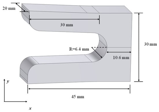
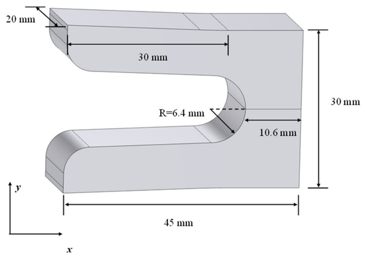
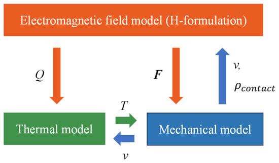
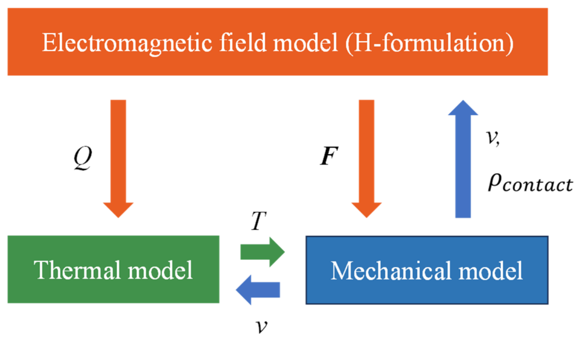
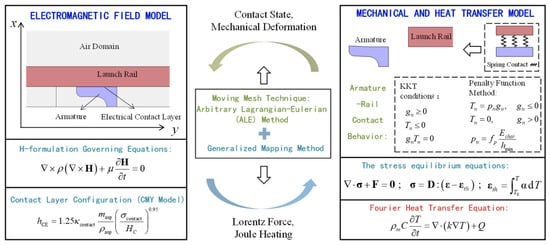
In this study, a 2.5 m long electromagnetic railgun system is investigated. The armature model and its geometric dimensions are illustrated in Figure 1. The total mass of the projectile is 220 g, consistent with that used in subsequent experiments. An electromagnetic–thermal–mechanical coupled model is established to simulate the interference fit during assembly and the electromagnetic launch process, as illustrated in Figure 2. The electromagnetic behavior of the railgun, including skin effect considerations, is calculated through the electromagnetic field model. The resulting Joule heat is coupled into the thermal model to determine the temperature distribution, while the computed Lorentz forces and temperature fields are subsequently integrated into the mechanical model to analyze the structural response. The mechanical model calculates armature displacement, which is then fed back into both the thermal and electromagnetic models through an Arbitrary Lagrangian–Eulerian (ALE) approach with dynamic meshing to accurately track armature motion.
Figure 1.
Schematic diagram of the armature model with key geometric dimensions.
Figure 2.
Schematic diagram of the electromagnetic–thermal–mechanical coupled model, where Q denotes the Joule heating, F represents the Lorentz force, T indicates the temperature field, and v and respectively represent the armature velocity and contact resistivity.
To compute the magnetic field and current density, the H−formulation method is employed. When accounting for the motion of conductive components, the governing equations for the H−method are expressed as
In the governing equations, H denotes the magnetic field intensity vector, and μ represents the material permeability. The current density is given by . The resistivity ρ is determined by material properties in the armature and rail domains. The contact interface between the armature and rail is modeled using a thin representative layer. The Cooper–Mikic–Yovanovich (CMY) model provides the governing framework for contact resistance prediction [30], with current transmission through the armature–rail interface expressed as
where and represent the current densities of the two contact surfaces, V1 and V2 denote the electrical potentials of the respective surfaces, and are the electrical conductivities of the contacting materials, indicates the contact conductivity, hCE stands for the constriction conductance, corresponds to the contact pressure, masp describes the average slope of surface asperities, ρasp represents the average height of asperities, and Hc signifies the microhardness of the contact interface. The relevant parameters are typical values for precision−machined surfaces and are listed in Table 1.
Table 1.
Contact model parameters used in the CMY model.
The Joule heat density is calculated as
where E is the electric field. The Joule heat source term is calculated as the volumetric power density in W/m3 and is directly substituted into the heat transfer equation.
During electromagnetic launch, the railgun experiences significant temperature rise due to Joule heating. To analyze this thermal behavior, a heat transfer model is employed, which shares the same geometric configuration as the electromagnetic field model for consistent multiphysics coupling. The governing equation for the heat transfer model is given by
where ρm is the density, and C and k are the heat capacity and thermal conductivity, respectively. Given the extremely transient nature of electromagnetic launch, convective heat transfer with ambient air is neglected in this study. Consequently, adiabatic boundary conditions are applied to all external surfaces. Frictional heating is localized at the contact surface and has negligible influence on the bulk thermal expansion in the present model. In consideration of the convergence behavior of the coupled model, frictional heating has not been incorporated in the current model.
To investigate the mechanical behavior of the electromagnetic railgun during both the assembly and launch processes, a discrete mechanical model incorporating contact pairs between the armature and rails is developed and coupled with the electromagnetic and thermal models. To prevent rigid−body displacement of the rails, the upper surface of the rail is constrained. The stress equilibrium and geometrical equations, including the electromagnetic force, are expressed as
where the stress tensor characterizes the internal forces within the railgun; represents the strain tensor; displacement denotes the spatial shifts experienced by points within the railgun; and represents the electromagnetic force, which is calculated by the magnetic field and the current density
This force acts on both the armature and the rails due to their conductive properties and the resulting electromagnetic interaction. represents the frictional stress, which acts exclusively at the contact interface between the armature and the rails, as defined by the Coulomb friction model
where is the coefficient of friction. Since this parameter is difficult to determine a priori and may vary during launch due to changes in contact conditions, it is selected by matching the simulated muzzle exit time to the experimental value, giving = 0.25 in the present study. This parameter is not independently measured, and the validation of other predicted quantities, such as contact resistance evolution, remains independent of this calibration. is the unit tangential vector in the direction of relative sliding motion.
The constitutive relation between strain and stress is
The elasticity tensor can be expressed in terms of equivalent Young’s modulus , Poisson’s ratio , and shear modulus . signifies the thermal strain tensor calculated from the temperature field T obtained in the thermal model. The thermal strain follows the standard thermoelastic relation
The electromagnetic railgun demonstrates complex armature–rail contact behavior under strong Lorentz forces. To accurately characterize the contact state and pressure distribution at the interface, the formulation employs the Karush–Kuhn–Tucker (KKT) conditions combined with a penalty function method. Within the mechanical sub−model, dynamic interfacial contact between the armature and rails is explicitly modeled, providing the basis for calculating the resulting contact resistance variation throughout launch. The contact pressure at the armature–rail interface is used to compute real−time contact resistance, which is iteratively coupled back into the electromagnetic model to refine current distribution calculations.
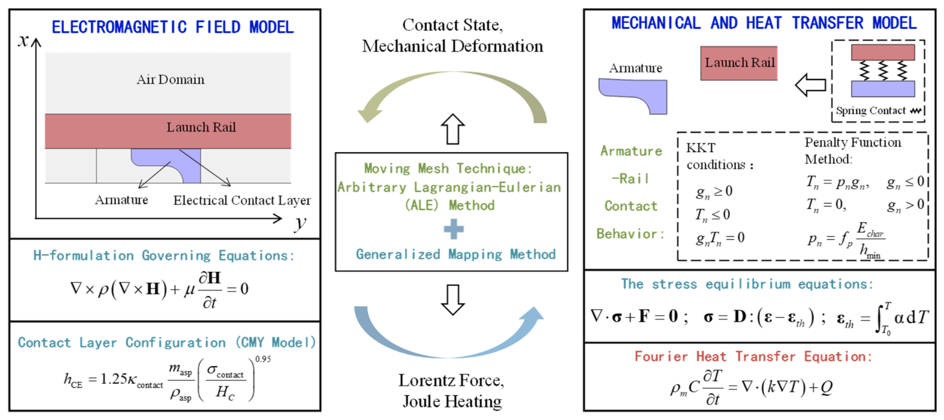
Figure 3 shows the schematic of the electromagnetic–thermal–mechanical coupled modeling methodology and computational workflow. In this coupled framework, the specific contributions are the inclusion of the assembly process, the introduction of the KKT conditions for contact state characterization, and the use of the CMY model for contact resistance calculation, enabling a full−cycle simulation from assembly to launch. The material properties used in the simulation are summarized in Table 2. The rail and armature materials are modeled as copper and aluminum, respectively, with their properties taken as standard values for these metals. For simplicity, all material parameters are treated as constants. In this study, the coupled model is solved using finite element methods. Initial values are set to zero before energization, and the subsequent evolution is driven by the applied supply current. The two−dimensional model is adopted because the contact behavior mainly originates from the front−rear geometrical asymmetry of the armature. To ensure mesh−independent results, the air domains immediately ahead of and behind the armature were locally refined, as these regions are subject to stretching and compression during dynamic mesh motion. These air domains are discretized with 100 elements axially and 15 elements transversely, and the contact interface is locally refined with 30 elements along the contact region. A maximum time step of 2 × 10⁻⁵ s is imposed to adequately resolve the transient launch process. The solver uses a fully coupled monolithic approach with a direct linear solver and implicit backward differentiation formula time integration. Note that this simplification, however, is difficult to consider for convex or concave rail structures.
Figure 3.
Schematic of the electromagnetic–thermal–mechanical coupled modeling methodology and computational workflow.
Table 2.
Material properties used in the simulation.
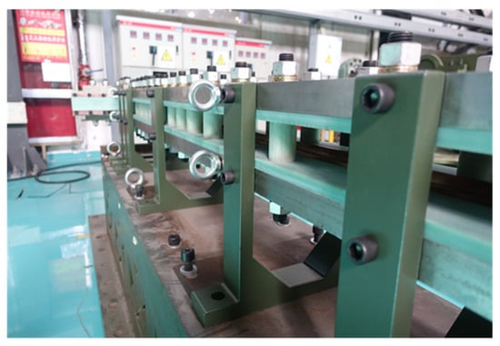
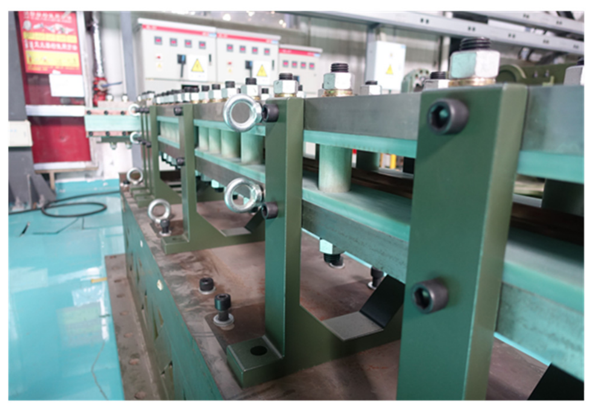
Experimental investigations are conducted using the open−bore electromagnetic railgun system illustrated in Figure 4. Real−time measurements capture both rail current and muzzle voltage . Rogowski coils measure the rail current. A Tektronix high−voltage probe with a 1:1000 attenuation ratio measures the muzzle voltage. Since the present experiments are based on a single−rail launcher configuration, the inductive voltage component and other voltage contributions are not present in this case. Since the armature resistance remains negligible compared to the contact resistance, as estimated by the expression [31] considering skin effect, the contact resistance is calculated as
Figure 4.
The open−bore electromagnetic railgun system used for experimental launch studies.
3. Simulation Results and Discussion
3.1. Assembly Process Analysis
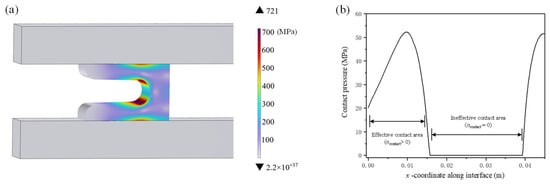
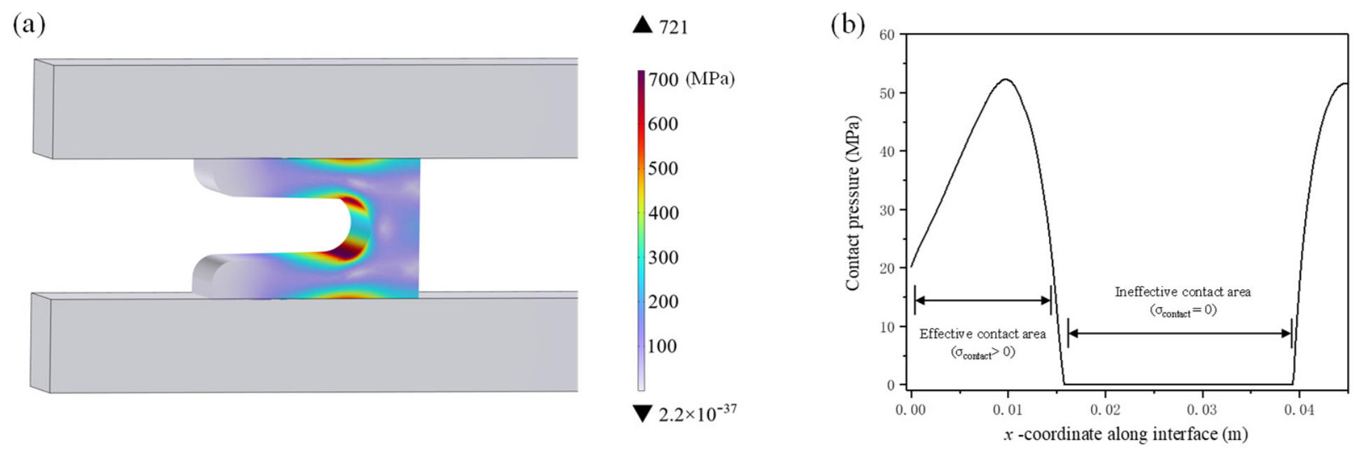
The electromagnetic railgun undergoes an assembly process prior to launch, which significantly influences the armature–rail mechanical behavior. Figure 5 presents the stress distribution in the armature and the contact pressure profile after assembly. Under a 1 mm interference fit condition, Figure 5a reveals that the armature develops substantial initial stress before launch, reaching a maximum of 721 MPa, with stress concentrations primarily occurring at two critical locations: the armature throat region and the central portion of the armature–rail interface. The contact pressure distribution in Figure 5b demonstrates non−ideal contact characteristics between the armature and rail. The contact pressure concentrates on both the leading and trailing edges of the armature, while the central region shows negligible values, indicating a lack of effective mechanical contact in this area. The initial interference fit at the tail end forces the armature to contact the rail primarily at the front and rear ends upon assembly. This configuration induces a significant bending moment within the armature body. Consequently, the midsection experiences high internal bending stresses, leading to the observed stress concentration in Figure 5a. However, because this region is not in direct compressive contact with the rail surface but is elastically bent away from it, the resultant contact pressure remains minimal. This non−uniform contact pattern may influence current conduction and the launch dynamics of the electromagnetic railgun system.
Figure 5.
(a) Stress distribution in the armature after assembly, with concentrations at the throat and the central portion of the armature–rail interface; (b) contact pressure distribution along the axial direction (x−coordinate) of the armature–rail interface after assembly, showing concentration at the leading and trailing edges and negligible pressure in the central region.
3.2. Electromagnetic Launch Process
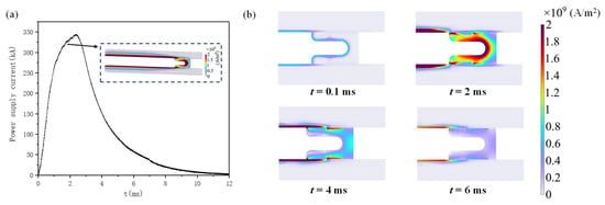
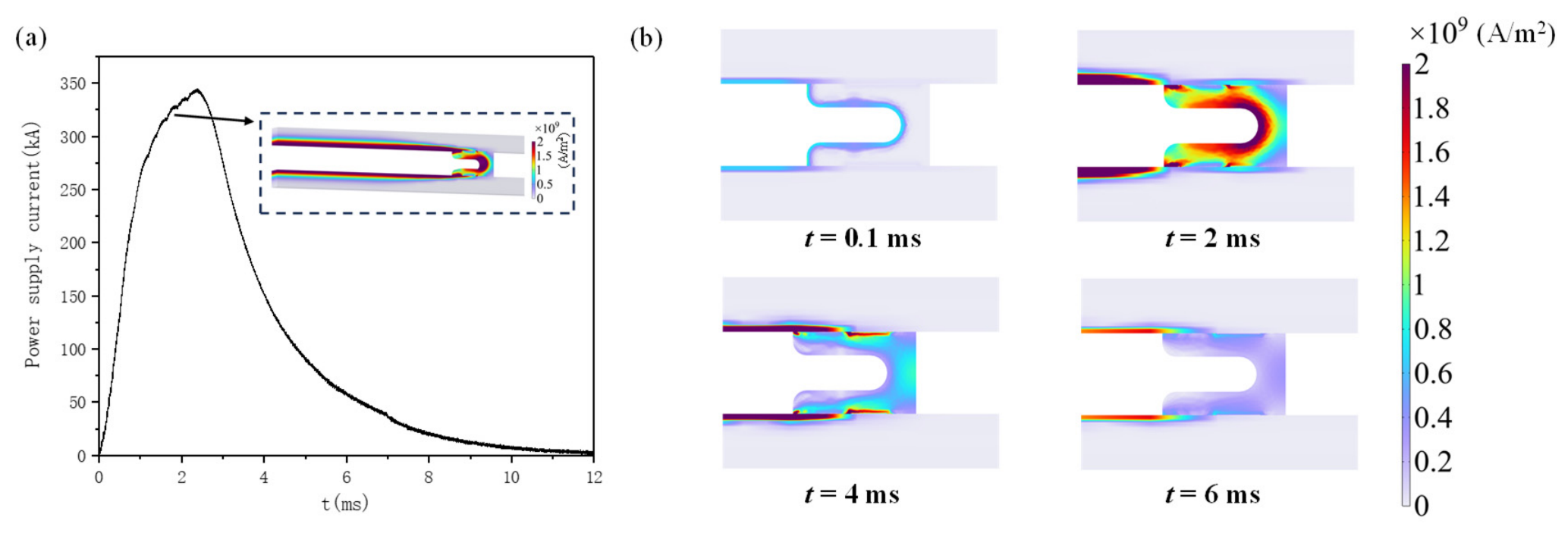
The launch process is further simulated using the geometric configuration and stress results from the assembly phase as initial conditions, with the total current constraint applied to the rail as shown in Figure 6a (consistent with subsequent experimental measurements). Figure 6b illustrates the current density distribution in the electromagnetic railgun during launch, revealing significant skin effect characteristics where current flows predominantly along the inner surfaces of the armature and rail. It should be noted that the current distribution near the armature–rail contact interface exhibits non−uniform characteristics, which directly correlates with the effective contact area between the armature and rail. As the current increases, a larger region of the armature carries high current density. After 2.36 ms, the power supply current decreases rapidly, leading to a corresponding reduction in the armature current.
Figure 6.
(a) Power supply current waveform during electromagnetic launch; (b) armature current density distributions at different time instants, revealing skin effect with current concentrated along the inner surfaces.
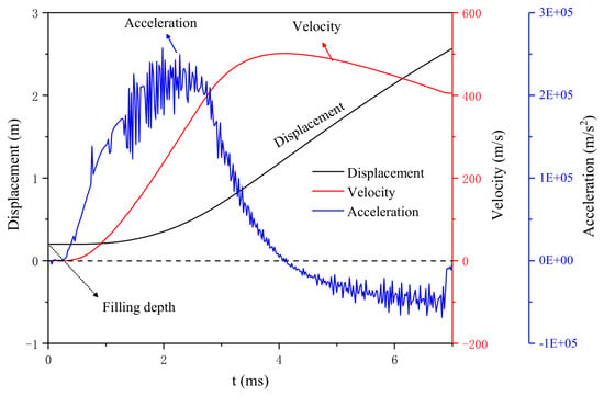
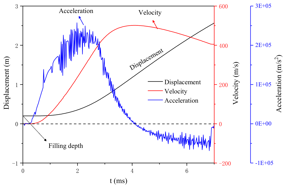
Figure 7 shows the armature’s displacement, velocity and acceleration profiles during launch. The armature acceleration profile correlates strongly with the power supply current variation, as the current magnitude directly determines the Lorentz force that propels the armature. In the initial phase, the rapidly increasing supply current leads to growing axial Lorentz force on the armature, resulting in increasing acceleration and rapid velocity rise. After 2.36 ms, when the supply current decreases sharply, the armature exhibits negative acceleration due to interference fit and friction effects, with slight velocity reduction before final muzzle exit. The maximum velocity reaches 501.4 m/s, and the muzzle velocity is 405.8 m/s. As shown in Table 3, a quantitative comparison between the simulation and experimental results is presented for the armature muzzle velocity and the muzzle exit time. The simulation yields a muzzle velocity of 405.8 m/s and an exit time of 6.78 ms, while the experimental measurements are 456.5 m/s and 6.91 ms, respectively. The experimental muzzle velocity was determined from the time interval measured by two B−dot probes spaced 100 mm apart near the muzzle. The relative errors are approximately 11.1% for velocity and 1.88% for exit time, which are considered acceptable given the complexity of the physical process.
Figure 7.
The armature’s displacement, velocity and acceleration profiles during launch.
Table 3.
Comparison of simulated and experimental results for armature velocity and muzzle exit time. The case corresponds to a peak supply current of 344.69 kA.
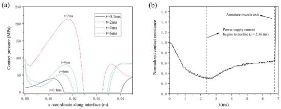
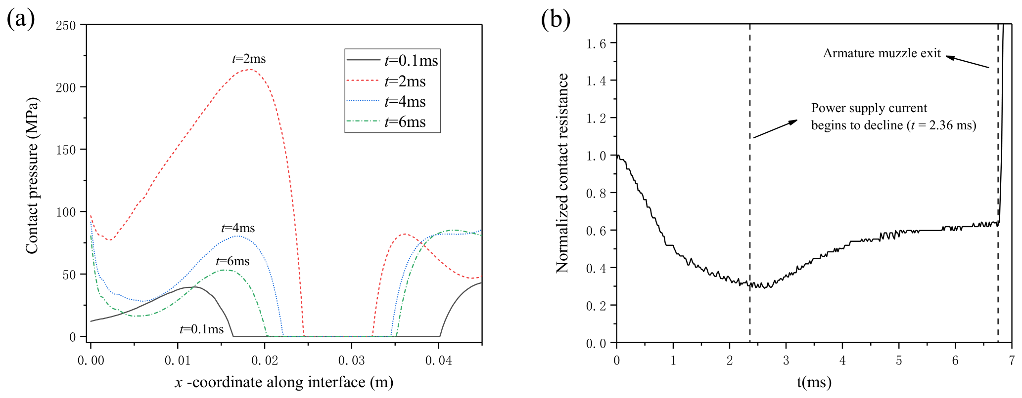
The contact pressure distribution on the armature–rail interface during the launch process is illustrated in Figure 8a, where the initial distribution represents the contact pressure after assembly. As the supply current increases, more regions develop contact pressure, indicating enhanced effective contact areas. Conversely, when the supply current decreases, both the contact pressure magnitude and the effective contact area reduce. The maximum contact pressure reaches 227.42 MPa at t = 2.1 ms. To visualize the variation trend of the armature–rail contact resistance during launch, the normalized contact resistance is presented in Figure 8b, derived from the average contact resistivity and effective contact regions on the armature–rail interface . The reference value is taken as the initial state immediately after assembly. The effective contact area after assembly is 46.99% of the nominal contact area. It is worth noting that direct quantitative comparison of the contact resistance is particularly challenging in the present study. The contact resistance is influenced by numerous complex factors during the launching process, such as armature melting, rail wear, and surface degradation, which are difficult to fully incorporate into the simulation model. Moreover, in the finite element simulation, only the resistance at individual contact spots can be computed, while a rigorous and physically meaningful definition of the overall contact resistance for the entire contact interface is not well established. This approach captures the combined effects of contact area enlargement and local resistivity variation, which are the two key factors governing contact resistance evolution in our coupled model. The contact resistance exhibits a rapid decrease within the first 1 ms of the launch process. After 2.36 ms, although the supply current drops sharply, the contact resistance does not rise abruptly but instead shows a gradual upward trend, reaching a minimum value of 0.290 at 2.62 ms and gradually rising to 0.619 at muzzle exit, maintaining a relatively low value throughout this stage, which signifies stable contact conditions. The underlying mechanisms of this phenomenon are analyzed in detail below.
Figure 8.
(a) Contact pressure distribution along the x−direction at different time instants during launch; (b) normalized contact resistance versus time, showing a rapid initial drop followed by a gradual increase.
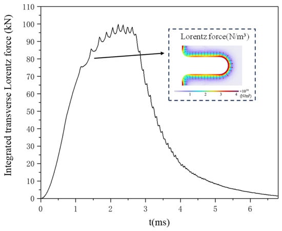
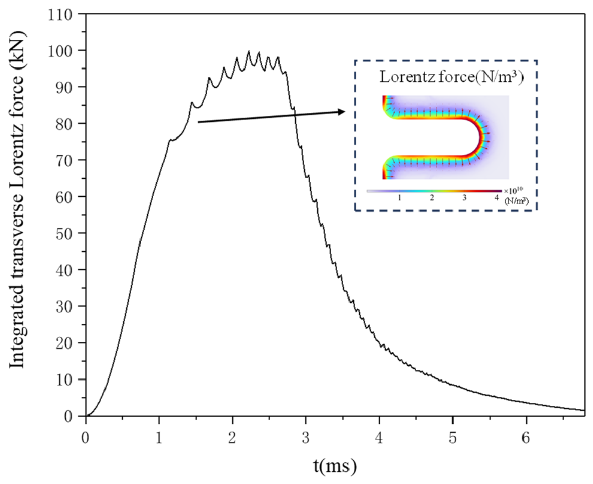
Figure 9 presents the integrated transverse component of Lorentz force acting on the C−shaped armature during launch. During 1–2.36 ms, the transverse Lorentz force increases rapidly with rising current due to the armature’s structural characteristics that generate substantial axial current (i.e., parallel to the launch direction). This current interacts with the magnetic field to produce significant transverse Lorentz force, which creates an outward expansion force on the armature. This expansion force enhances rail−armature contact by increasing both contact pressure and effective contact area, explaining the rapid contact resistance reduction observed in Figure 8b during the early phase. However, the Lorentz force alone cannot fully explain the contact resistance behavior during the later phase, which is better interpreted by the competing mechanisms between electromagnetic forces and thermal effects.
Figure 9.
Temporal variation in the integrated transverse Lorentz force component in the armature during electromagnetic launch.
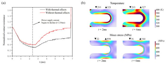
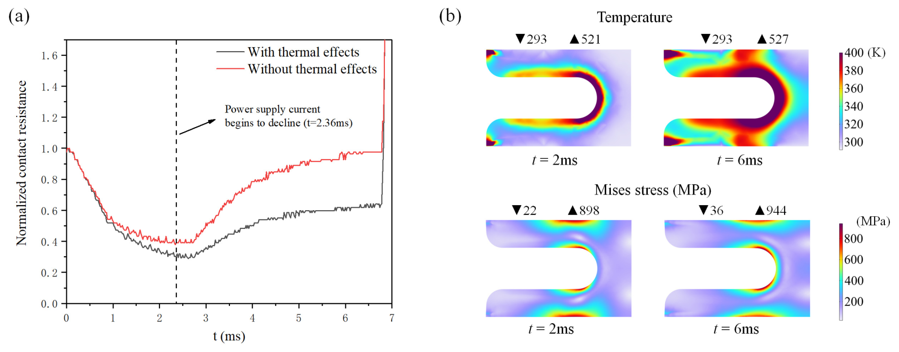
Figure 10a compares the evolution of normalized contact resistance with and without thermal effects. When thermal effects are neglected, the contact resistance first decreases to a minimum of 0.379 at t = 2.34 ms. This minimum is higher than that when thermal effects are considered, and it nearly coincides with the onset of the current drop. The resistance then increases rapidly as the transverse Lorentz force diminishes, eventually reaching 0.976 at muzzle exit, returning to a value close to its pre−launch state. In contrast, when thermal effects are considered, the resistance exhibits a much slower increase despite the sharp decline in Lorentz force, because the persistent thermal stress in the armature maintains relatively low resistance throughout the later stage. Figure 10b shows the armature distributions of temperature and stress at different time points. The temperature distribution follows the skin effect pattern, with higher temperatures concentrated along the armature’s inner surface. It can be found that the armature maintains an elevated temperature despite the rapid current decline. At t = 2 ms, corresponding to high supply current conditions, the maximum temperature within the armature reaches 521 K. Subsequently, at t = 6 ms, under conditions of relatively low current, the maximum temperature persists at 527 K. This phenomenon arises from significant Joule heating accumulation during the early phase, which elevates the armature temperature substantially. The extreme rapidity of electromagnetic launch results in minimal heat dissipation between the railgun system and its surrounding environment during the short duration. Consequently, the armature maintains high temperature during the later phase, exhibiting even a slight increase due to continued Joule heating accumulation. This thermal effect generates sustained expansion forces that continue to act on the armature structure. At t = 2 ms, the maximum von Mises stress in the armature reaches 898 MPa, increasing to 944 MPa at t = 6 ms. Under thermal stress effects, the armature–rail interface maintains relatively stable contact conditions, directly accounting for the gradual contact resistance increase shown in Figure 10a.
Figure 10.
(a) Comparison of normalized contact resistance variations with and without thermal effects; (b) temperature and stress distributions in the armature at different time instants during launch.
4. Experimental Data Analysis
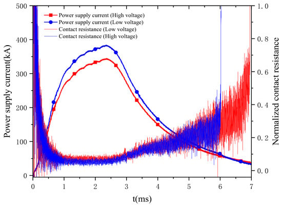
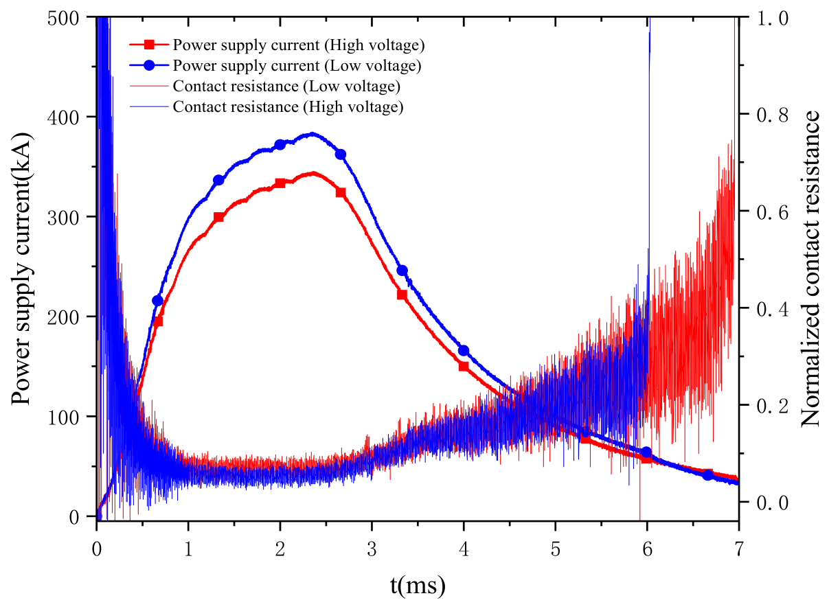
Based on the open−bore launch experiments conducted under varying power supply currents, the armature–rail contact resistance calculated from muzzle voltage measurements is shown in Figure 11. The sampling rate was 3 MHz, and the raw sampled data were used directly without any fitting or smoothing, which inevitably introduces some noise, but the variation trend of contact resistance remains clearly identifiable. The test results are consistent with published results in References [32,33]. The results demonstrate that during the early launch phase, the contact resistance rapidly decreases within a short duration, followed by a gradual increase as the supply current declines, a behavior that matches numerical simulations. This variation trend further demonstrates the combined influence of transverse Lorentz forces and thermal stress effects on the armature–rail contact behavior. The faster decrease in contact resistance observed in the experiments may be related to melting at the interface, which is not included in the current model [2]. This omission may affect quantitative agreement and could lead to an overestimation of contact resistance throughout the launch process except for the assembly stage. Nonetheless, the overall trend and the mechanistic interpretation remain reliable. In addition, comparative analysis of the two current conditions indicates that higher supply current consistently yields lower contact resistance throughout the entire launch process than the lower current condition. The total number of tests was nearly 100 shots under various armature types and operating conditions. The occurrence rate of abnormal launches was less than 10%. All tests consistently exhibited the same characteristic trend, confirming the reliability and repeatability of the experimental results. Only typical cases are shown in the figures.
Figure 11.
Armature–rail contact resistance calculated from muzzle voltage measurements in open–bore launch experiments under different power supply currents.
5. Parametric Study Under Varied Operating Conditions
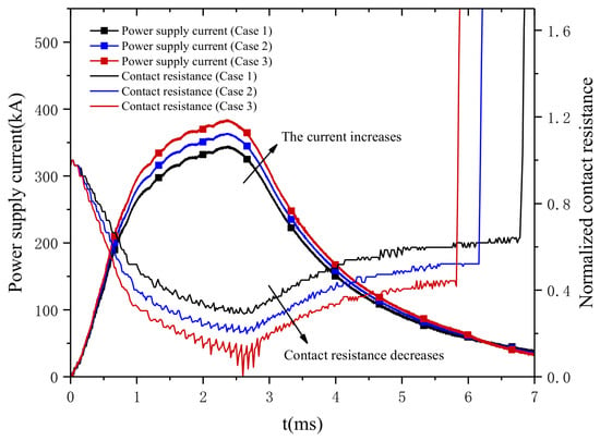
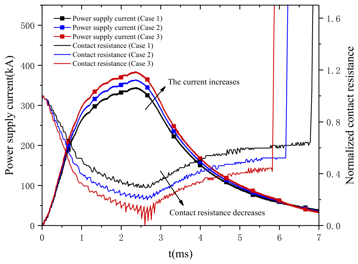
The simulated contact resistance variations under different power supply currents during the launch process are presented in Figure 12, demonstrating consistent trends with experimental measurements where higher currents yield improved interfacial contact conditions. For the three current levels considered, the normalized contact resistance at muzzle exit is 0.619 for a peak current of 344.7 kA, 0.522 for 363.7 kA, and 0.443 for 384.1 kA, respectively. This enhancement stems from two synergistic effects: stronger transverse Lorentz forces during the early acceleration phase, and elevated thermal expansion from increased Joule heating, which maintains greater armature dilation forces throughout the launch sequence. However, the relationship between current magnitude and contact quality does not always exhibit a linear dependence. While moderate current enhancement improves contact conditions, excessive current leads to significantly higher armature velocity, temperature, and mechanical loads, resulting in a more severe bore environment. Under such extreme conditions, the armature–rail interface becomes highly prone to transition phenomena where the contact resistance experiences sudden and significant increases, adversely affecting the launch process. This study provides a theoretical reference for engineering practice by showing that, under normal conditions, increasing current is beneficial for reducing contact resistance. When abnormal resistance rise is observed, the cause should be sought in other factors such as rail damage, aluminum deposition, or armature structural failure, rather than the current level alone.
Figure 12.
Simulated normalized contact resistance variations under different power supply currents obtained from the coupled electromagnetic–thermal–mechanical model.
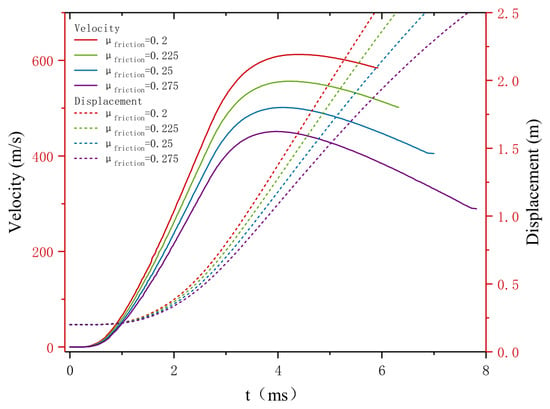
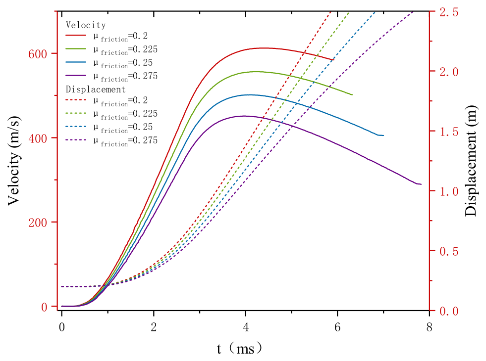
Figure 13 presents the armature velocity and displacement profiles for friction coefficients ranging from 0.2 to 0.275. The corresponding muzzle velocities are 584.43 m/s for μfriction = 0.2, 501.77 m/s for μfriction = 0.225, 405.01 m/s for μfriction = 0.25, and 289.23 m/s for μfriction = 0.275. The displacement curves follow a consistent trend, with higher friction resulting in lower velocity and shorter travel distance. It should be noted, however, that the friction coefficient is influenced by multiple factors, such as interference fit, rail surface condition, and armature melting—and is difficult to determine precisely in practice. The present comparison therefore serves as a reference for understanding the influence of this parameter on the dynamic response. In our model, the contact resistance is primarily governed by the Lorentz force and thermal expansion, rather than by friction; the variation in friction coefficient does not affect the main conclusions regarding contact resistance evolution.
Figure 13.
Armature velocity and displacement profiles for different friction coefficients (μfriction = 0.2, 0.225, 0.25, and 0.275).
6. Conclusions
The main novelty of this work lies in the coupling of mechanical contact behavior with contact resistance calculation, and in the inclusion of the assembly process, which together provide a complete simulation framework. The analysis reveals a characteristic contact resistance pattern featuring a rapid initial decrease followed by a gradual increase, with a minimum normalized value of 0.290 at 2.62 ms and a muzzle−exit value of 0.619. The underlying mechanism is identified as a transition in dominance. Transverse Lorentz forces govern the early stage by enlarging the effective contact area, while thermal expansion takes over in the later stage to maintain contact pressure and preserve favorable contact conditions. The maximum temperature and von Mises stress reach 527 K and 944 MPa, respectively, during the launch process. These findings provide fundamental insights into the multiphysics mechanisms governing armature–rail contact behavior in railgun systems.
Several limitations of the present study should be acknowledged. Quantitative comparison of contact resistance with experiments remains difficult because the actual contact resistance is influenced by multiple complex factors, such as armature melting, rail wear, and surface degradation, which are not fully captured in the current model. The two−dimensional geometry employed here cannot accurately represent the arched rail surfaces that are commonly used in actual railgun systems. In future work, we will extend the model to three dimensions to accommodate realistic rail geometries and will incorporate wear and melting effects to enable more comprehensive and quantitative validation.
Author Contributions
Conceptualization, T.Z.; Methodology, Y.L.; Software, D.W.; Validation, W.W.; Data curation, W.W.; Writing—original draft, D.L.; Writing—review & editing, D.W.; Funding acquisition, D.L. All authors have read and agreed to the published version of the manuscript.
Funding
This research was funded by the Fund of Natural Science Foundation of China, grant number 12502246, and the Innovation Capability Support Program of Shaanxi, grant number 2025RC-YJRC-007.
Data Availability Statement
The raw data supporting the conclusions of this article will be made available by the authors on request.
Conflicts of Interest
The authors declare no conflict of interest.
References
- Ma, W.; Lu, J.; Liu, Y. Research Progress of Electromagnetic Launch Technology. IEEE Trans. Plasma Sci. 2019, 47, 2197–2205. [Google Scholar] [CrossRef] [Scilit]
- Li, B.-M.; Lin, Q.-H. Analysis and discussion on launching mechanism and tactical electromagnetic railgun technology. Def. Technol. 2018, 14, 484–495. [Google Scholar] [CrossRef] [Scilit]
- Guan, S.; Guan, X.; Wu, B.; Shi, J. Analysis of the Influence of System Parameters on Launch Performance of Electromagnetic Induction Coil Launcher. Energies 2022, 15, 7803. [Google Scholar] [CrossRef] [Scilit]
- Xie, H.-B.; Yang, H.-Y.; Yu, J.; Gao, M.-Y.; Shou, J.-D.; Fang, Y.-T.; Liu, J.-B.; Wang, H.-T. Research progress on advanced rail materials for electromagnetic railgun technology. Def. Technol. 2021, 17, 429–439. [Google Scholar] [CrossRef] [Scilit]
- Fair, H.D. Advances in Electromagnetic Launch Science and Technology and Its Applications. IEEE Trans. Magn. 2009, 45, 225–230. [Google Scholar] [CrossRef]
- Tian, W.; Wang, G.; Zhao, Y.; Zhao, W.; Yuan, W.; Yan, P. Effects of Driving Current Ripple Fluctuations on the Liquefied Layer of the Armature–Rail Interface in Railguns. Energies 2025, 18, 2596. [Google Scholar] [CrossRef] [Scilit]
- Bedford, A. Rail damage and armature parameters for different railgun rail materials. IEEE Trans. Magn. 1984, 20, 352–355. [Google Scholar] [CrossRef] [Scilit]
- Ma, S.; Ma, H. Investigation on Dynamic Thermal Transfer Characteristics of Electromagnetic Rail Spray Cooling in Transient Processes. Energies 2025, 18, 5254. [Google Scholar] [CrossRef] [Scilit]
- Kothmann, R.E.; Stefani, F. A thermal hydraulic model of melt−lubrication in railgun armatures. IEEE Trans. Magn. 2001, 37, 86–91. [Google Scholar] [CrossRef] [Scilit]
- Barber, J.P.; Challita, A.; Maas, B.; Thurmond, L. Contact transition in metal armatures (railguns). IEEE Trans. Magn. 1991, 27, 228–232. [Google Scholar] [CrossRef] [Scilit]
- Barber, J.P.; Challita, A. Velocity effects on metal armature contact transition (railguns). IEEE Trans. Magn. 1993, 29, 733–738. [Google Scholar] [CrossRef] [Scilit]
- Liu, Y.; Guo, W.; Zhang, T.; Zhang, H.; Fan, W.; Su, Z. Structural Design of Armature With Interference at Both Ends and Analysis of Its Launching Performance. IEEE Trans. Plasma Sci. 2020, 48, 2922–2931. [Google Scholar] [CrossRef] [Scilit]
- Li, C.; Xia, S. Study on Lubrication Characteristics of Metal Liquid Film Based on Electromagnetic−Elastic Mechanics−Hydrodynamics Multiphysics Coupling Model. Materials 2020, 13, 1056. [Google Scholar] [CrossRef] [Scilit] [PubMed]
- Consolo, V.; Musolino, A.; Rizzo, R.; Sani, L. Numerical 3D Simulation of a Full System Air Core Compulsator−Electromagnetic Rail Launcher. Appl. Sci. 2020, 10, 5903. [Google Scholar] [CrossRef] [Scilit]
- Kwon, Y.; Pratikakis, N.; Shellock, M. Multiphysics modeling of a rail gun launcher. Int. J. Multiphys. 2008, 2, 421–436. [Google Scholar] [CrossRef] [Scilit]
- Wang, G.; Tian, W.; Zhao, W.; Zhao, Y.; Yuan, W.; Yan, P. Modeling the temperature evolution of electromagnetic rails under multiphysics coupling. Case Stud. Therm. Eng. 2025, 75, 107177. [Google Scholar] [CrossRef] [Scilit]
- Hsieh, K. A Lagrangian formulation for mechanically, thermally coupled electromagnetic diffusive processes with moving conductors. IEEE Trans. Magn. 1995, 31, 604–609. [Google Scholar] [CrossRef] [Scilit]
- Newill, J.F.; Powell, J.D.; Zielinski, A.E. Coupled finite−element codes for armature design. IEEE Trans. Magn. 2003, 39, 148–152. [Google Scholar] [CrossRef]
- Lin, Q. Multifield and Multiscale Modeling of Armature Wear in Electromagnetic Railgun. IEEE Trans. Plasma Sci. 2022, 50, 1971–1976. [Google Scholar] [CrossRef] [Scilit]
- Du, P.; Lu, J.; Li, X.; Feng, J.; Li, K. Interior Ballistic Characteristics of Electromagnetic Rail Launcher Considering the Dynamic Characteristics of Real Launcher. IEEE Trans. Ind. Electron. 2021, 68, 6087–6096. [Google Scholar] [CrossRef] [Scilit]
- Yan, J.; Li, J.; Ren, R.; Chen, Y.; Wang, Y.; Chen, Y.; Huang, K. System Noise Suppression of Muzzle Voltage in Augmented Electromagnetic Railgun Based on VMD and the Application in Armature–Rail Contact Characteristics. IEEE Trans. Plasma Sci. 2022, 50, 502–509. [Google Scholar] [CrossRef] [Scilit]
- Ge, X.; Cao, B.; Wang, Z.; Pei, P.; Huang, K.; Chen, Y.; Fan, W.; Zhang, T. Research on the Contact Characteristics Between Armature and Rail of the Enhanced Electromagnetic Rail Gun Based on the New Aluminum Alloy Armature. IEEE Trans. Plasma Sci. 2023, 51, 3703–3708. [Google Scholar] [CrossRef] [Scilit]
- Xu, W.; Yuan, W.; Sun, Y.; Yan, P.; Li, J. Research on the Sliding Electrical Contact of the Rapid Fire Railgun. IEEE Trans. Plasma Sci. 2013, 41, 1542–1546. [Google Scholar] [CrossRef] [Scilit]
- Zhu, C.-Y.; Li, B.-M. Analysis of sliding electric contact characteristics in augmented railgun based on the combination of contact resistance and sliding friction coefficient. Def. Technol. 2020, 16, 747–752. [Google Scholar] [CrossRef] [Scilit]
- Wang, Z.; Chen, L.; Ren, Y.; Xu, J.; You, P.; Lan, X.; Ge, Y.; Xia, S. Muzzle Voltage of Conventional and Augmented Railguns. IEEE Trans. Plasma Sci. 2022, 50, 3802–3808. [Google Scholar] [CrossRef] [Scilit]
- Xu, J.; Xia, S.; Yang, H.; Chen, L. Coupled Mechanical and Electromagnetic Analysis of Current on Armature and Rail Interface With Dynamic Contact. IEEE J. Multiscale Multiphys. Comput. Tech. 2024, 9, 198–207. [Google Scholar] [CrossRef] [Scilit]
- Yao, J.; Zhang, T.; Fu, Q.; Wu, S. Influence of Melting State of Deposited Layer at Electromagnetic Launch Sliding Electrical Contact Interface on Armature Melting. Electronics 2024, 13, 5017. [Google Scholar] [CrossRef] [Scilit]
- Liu, F.; Han, Y.; Gao, X.; Lu, T.; Zhang, H. Temporal and Spatiotemporal Evolution Distribution Characteristics of Friction and Wear of Electromagnetic Launcher. IEEE Trans. Plasma Sci. 2025, 53, 334–342. [Google Scholar] [CrossRef] [Scilit]
- Qin, T.; Shu, T.; Bian, J.; Xin, Z. Electromagnetic railgun contact resistance simulation study. In Proceedings of the 2023 3rd International Conference on Electrical Engineering and Mechatronics Technology (ICEEMT); IEEE: New York, NY, USA, 2023; pp. 380–383. [Google Scholar]
- Yovanovich, M.M. Four decades of research on thermal contact, gap, and joint resistance in microelectronics. IEEE Trans. Compon. Packag. Technol. 2005, 28, 182–206. [Google Scholar] [CrossRef] [Scilit]
- Yu, X.J.; Fan, Z.N. Simulation and two−objective optimization of the electromagnetic−railgun model considering VSEC resistance and contact resistance. IEEE Trans. Plasma Sci. 2011, 39, 405–500. [Google Scholar] [CrossRef] [Scilit]
- He, Y.; Song, S.; Guan, Y.; Cheng, C.; Gao, G.; Li, Y.; Qiu, X. Quantitative expression of sliding contact resistance between armature and rail in railgun. High Power Laser Part. Beams 2014, 26, 045007. [Google Scholar] [CrossRef] [Scilit]
- Wang, Z.C.; Bao, Z.Y.; Cao, H.Y.; Liu, F.C.; Zhan, Z.J.; Wang, D.Z. Research on contact characteristics of armature and rail in augmented electromagnetic railgun. Binggong Xuebao/Acta Armamentarii 2018, 39, 451–456. [Google Scholar]

Disclaimer/Publisher’s Note: The statements, opinions and data contained in all publications are solely those of the individual author(s) and contributor(s) and not of MDPI and/or the editor(s). MDPI and/or the editor(s) disclaim responsibility for any injury to people or property resulting from any ideas, methods, instructions or products referred to in the content. |
© 2026 by the authors. Licensee MDPI, Basel, Switzerland. This article is an open access article distributed under the terms and conditions of the Creative Commons Attribution (CC BY) license.