


Abstract
Texture is indispensable in image-based rendering. In order to obtain realistic and aesthetic texture, a simple and effective texture synthesis method based on vector field is presented in this paper. A sufficient large, progressively-variant, aperiodic texture can be generated from a small texture sample based on the proposed method. The main contributions in this method are anisometric synthesis and appearance control. Anisometric synthesis is attained by using an expanded sample structure called the warping image stack, together with a quadrant searching step and a continuity matching approach. Appearance control is achieved by associating each partition of the texture to a certain guiding vector, which arranges the partition to have corresponding local rotation and scaling. The experiments show that our method can produce textures with natural and flexible effect.
1. Introduction
Texture synthesis technique plays an active role in several fields, such as image processing and 3D surface decorating. Specifically, in the jacquard CAD system, since the diversity of clothing styles lead to a large demand for variant textures, it is very meaningful to synthesize novel views from sample textures captured in the real world instead of recreating the entire physical world from scratch.
Most approaches about sample-based texture synthesis focus on how to eliminate the seams, while ignoring the importance of distinctive appearance of texture. In order to meet the requirement of application, texture design in jacquard CAD is required with complex structure and flexible appearance. From the simulation point of view, the real world textures are irregular, such as animal skin patterns are often with a variety of vortexes. On the other hand, from the artistic design point of view, the appearance of flexible design provides a wider space for designers to develop their creative. While for such purposes, a designer may have to spend extra time debugging parameters or using some image editor tools on the synthesized texture.
In this paper, we specifically propose a new texture synthesis method based on vector field. According to the properties of vector field, the texture synthesis performances of irregular, fluency and so on can be obtained sufficient. The main objectives and contributions are in two points: anisometric texture synthesis and intuitive user control. The original sample texture can be extended to a series of transformed texture samples, which contain multi-scale warping information. The connection of texture tile and guiding vector ensures the appearance of texture to be anisometric, smooth and controllable. This method can be used in the textile image synthesis and 3D garment rendering. The experiments show that the synthesis effects are natural and flexible.
2. Related Work
2.1. Texture Synthesis
Texture synthesis algorithms build on a long sequences of early papers, as such techniques are easy to use and capable of producing results without unnatural artifacts or periodicity. Various fields like game engines and feature animations have put it in to practical [1]. Most sample-based approaches are based on the Markov Random Field theory, modeling a texture as a realization of a local and stationary random process. According to the basic unit of treatment, these methods can be divided into pixel-based, patch-based, or more generally, optimization-based. The traditional pixel-based approach is to synthesize image in scan-line order, and compare synthesized neighborhoods to search the best matching pixel [2]. The improvement methods include hierarchical synthesis [3], coherent synthesis [4], and order-independent synthesis [5]. These methods are often perceived as inherently limited due to narrow neighborhoods and lack of global optimization. Sylvain Lefebvre [6,7] presented a high quality result with controllable aesthetic effect in real-time based on appearance space. However, the size of its synthesis result is fixed to some specific values, and multi-resolution may arise in different texture regions. Instead of synthesizing in pixel, patch-based approaches take patch as basic synthesis unit. Efros [8] proposed a patchbased method with fixed block size and used image quilting to eliminate the seams. Inspired by image quilting, Kawatra [9] and Cohen [10] optimized the seam problem and extend block size to arbitrary, while these improved algorithms are relatively time consuming and are not suitable for synthesizing large scale image. Extensions to perform texture synthesis on surfaces by forming seamless texture across atlas charts can be found in [11,12]. Recently, more information about texture synthesis are reported [13,14].
2.2. Vector Field
Vector fields arise from experiments, measurements and simulations in many scientific and engineering disciplines. It usually be used as an important analysis structure to understand underlying nature of the processes exhibiting a particular field or to be able to predict the system behavior in the real world. In a flexible and intuitive texturing system, users need to control the orientation and sizing of texture on surface. Such controls are often achieved by designing a vector field prescribing one of the axes of the local coordinate frames. Some vector field design tools use interpolation from scattered user-specified directions [15,16], and others also allow singularity control [17,18]. Zhang [17] proposed a method to use geodesic polar maps and parallel transport to create radial basis functions. Fisher [18] employed the tools from discrete exterior calculus, by representing the field as discrete 1-forms and solving linear equations with user-defined constraints, which includes source, sink, spiral and line. Users can use these constraints to generate desired vector fields.
In this paper, we develop a texture synthesis method based on vector field. The guiding vector fields in our paper are generated by the method in [18]. Through control of the vector field, we can intuitively design and control appearance of the result image.
3. Texture Synthesis Based on Vector Field
The main steps in our method include sample pretreatment, quadrant selection, block matching and minimum cut generation. Instead of using the original texture only, we create a series of transformed warping images as samples, which we called warping image stack. The transformed sample images are obtained by a differentiable warping function, with pixel offsets vary with stack level. The selection of stack level depends on the intensity of vector field. In the matching stage, we set the derivative at the boundary edge of two adjacent blocks to be the same, which ensures continues deformation. To reduce the seam, we take the length of boundary cut into consideration. The details of our method are presented in the following sections.
3.1. Warping Image Stack
In order to form anisometric texture synthesis, we need to consider the approach of twisting the image in local area. A direct idea is to rotate the image blocks in correspondence to the angle of guiding vector, and then splice these rotated blocks [19]. But this method will cause discontinues between adjacent blocks and multi-resolution in different regions, and hence it decreased the realism and naturalness of the result texture.
Our solution is to produce smooth deformation to the block both in the interior and the overlap region, which can be achieved by a warping function. For the original texture sample S0, we first synthesize a large texture as middle texture image Sm; and then apply appropriate deformation on the middle image Sm to get the deformed texture sample Sd. Let vm (xm,ym) denotes a coordinate in the source image, vd (xd,yd) denotes the corresponding coordinate in the deformed destination texture Sd. There is a function f : R2 → R2 that maps vd to vm:
vm = f (vd).
Since the warping function expands the original texture sample to transformed texture samples which are adapted to anisometric synthesis, it should meet the following properties:
- Differentiability. The deformation should be smooth.
- Plasticity. Through constructing parameters we can cover all the vectors.
- Periodicity. For each vector, we need to offer sufficient deformation candidates to reduce matching error. Hence, it is necessary for one deformation mold corresponding to multiply blocks.
Several kinds of functions such as polynomial function and spherical function can be used as warping function. Sine function based on comparative experiments is used in our method. For each pixel in the middle image, it will be in accordance with the sine law to offset a certain number both in directions of x-axis and y-axis. The deformation is captured more precisely by the expression:
where the parameters A and T are used to control the amplitude and period. Note that xm and ym may not be integers, bilinear interpolation is used in our method to calculate the color of vm.
However, the intensity of the vector field varies with different regions. The adjacent two vectors may have a phase difference or just near the same, but each block has a fixed size.
Consequently, our method has a more general solution, which is to allow each block to have fine resolution under different corresponding vector. Using the warping function discussed above, we build a series transformed samples S0, S2, ..., Sn, which we called warping image stack.
To create the warping stack, we specify a range of domains that, for each angle difference of the adjacent vectors, it will belong to a certain domain. We divide the interval into {0}, by controlling the parameters A in Eq. (3), for any subinterval [θi−1,θi], we have:
where the constant B is the block size. The stack level is defined by Ai. With the change of Ai value, the local region image will be deformed. Specially, let A0 = 0 for the situation that two adjacent vectors are identical, which just corresponds to the middle image synthesized above. Notice that , we set An to sufficient large as approximation. Since the vector field is locally sensitive, the angle difference of adjacent vectors just almost impossible occur to be . Figure 1 shows the local deformation under different image warping level. From this figure we can see, a serious of deformation about local region image can be obtained, and these deformations can be used in the texture synthesis process.
Figure 1.
Deformations in the same local region under different waping image stack level.
3.2. Selection and Matching
When the warping image stack has been formed, each block in the texture will be assigned with its corresponding stack level. The method is used to measure the similarity of adjacent blocks, that is, the corresponding level of warping stack of a block increases alone with the degree of difference between its adjacent blocks.
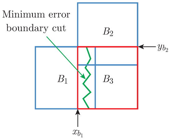
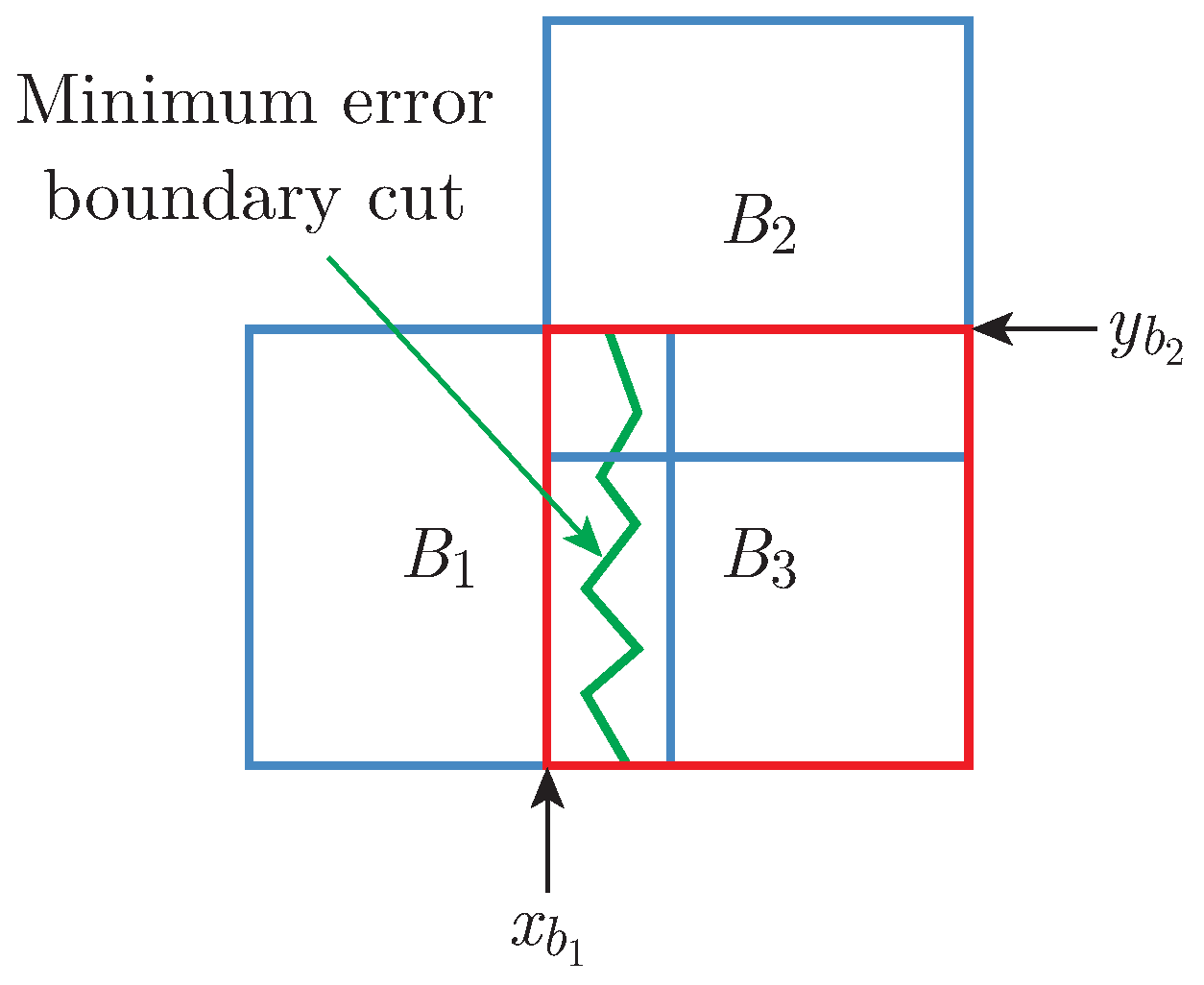
In general case, as shown in Figure 2, suppose B3 is a block which to be synthesized, B1 and B2 are horizontal and vertical synthesized adjacent blocks. To tile B3, we determine its corresponding warping stack level through calculating the difference between its synthesized adjacent blocks. The angle difference ∆θ of two vectors p and q is:
Figure 2.
B3 is the block to be synthesized, B1 and B2 are horizontal and vertical synthesized adjacent blocks.
Suppose the angle difference of B1 and B3 is ∆θ1 ∈ [θu−1,θu] and the angle difference of B2 and B3 is ∆θ2 ∈ [θv−1,θv], then we use the warping image in level u and v as sample images and search candidates in parallel.
In order to synthesize smooth image, we do not search candidate blocks pixel by pixel. Instead, we restrict that the derivative at the overlap boundary of adjacent blocks to be the same. For instance, for B1, suppose the coordinate of the boundary edge in respect to x-axis is xb1, and for B3 is xb3, the corresponding warping stack level of B1 and B3 are l1 and l3, then xb1 and xb3 satisfy the equation:
(fl1 (xb1))′ = (fl3 (xb3))′.
Eq. (5) just express the main idea of the matching stage. Each time when we connect two blocks, we make the derivative at the point of intersection maintain identical. Our method stores the stack level and location information after each selection of candidate, so the l1 and xb1 are known variable. Combine Eq. (3) and (6), xb3 can be defined in the equation:
Note that the block size cannot contain a whole monotone interval, we can use the vector angle of B3 to quit the excess solution. Eq. (6) produces a series of periodic value of xb3, which are the beginning horizontal coordinate of candidate blocks. Similar procedure can be applied to horizontal overlaps. The horizontal and vertical beginning coordinate bring us the locations of candidates, and the best one is picked by minimal the euler distance in the overlapping region.
3.3. Minimum Error Boundary Cut
Finally, we want to make the cut between two overlapping blocks on the pixels where two texture matches best. To make the two adjacent texture blocks match best, a minimum error cut is generated [8]. As shown in Figure 2, B1 and B3 are two blocks that overlap along their vertical edge with the regions of overlap B1ov and B3ov, the error surface is defined as . The minimal error E of all path in the overlap region is then computed:
Ei,j = ei,j + min(Ei−1,j−1,Ei−1,j,Ei−1,j+1).
However, in this generation of the cut, it offsets most one unit along advancing per pixel, so the curvature of the cut is no more than , which makes the cut not minimal globally. Especially when we use the warping image stack as sample textures, the minimal cut should be stretched to adapt to the deformed pixels. Hence in our method, we use the Bayesian method with roughness penalty to define the minimal error E:
where N is the length of the cut. We enable the cut to offset more than one unit in the generation, which stretches out the boundary cut. While a long cut might bring extra error in vision, hence we set the roughness penalty here controls large number of the cut length.
4. Experiment Results
The tests of our algorithm were performed on a regular laptop with Inter(R) Core 5 Dual with 4 GB memory. Each test ran for between 30 seconds and several minutes per image depending on the user-defined block size, image size in each stack level, and the hierarchy of warping image sack.
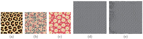
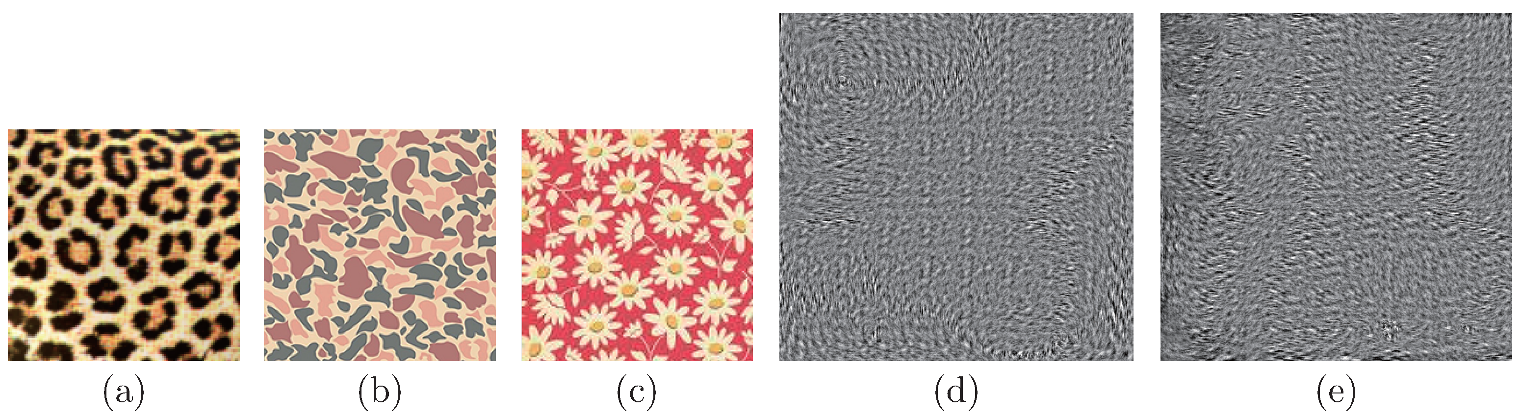
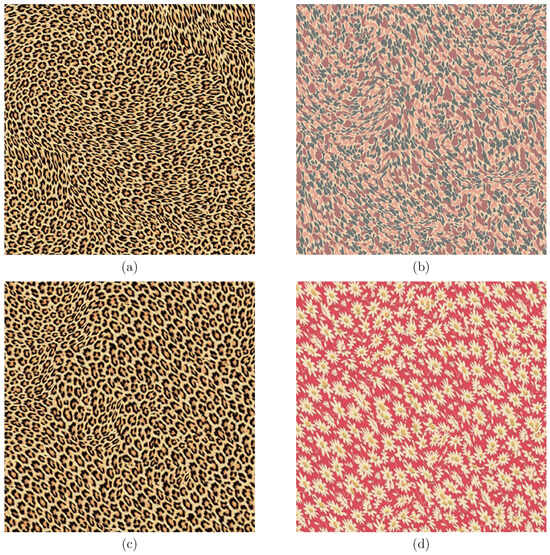
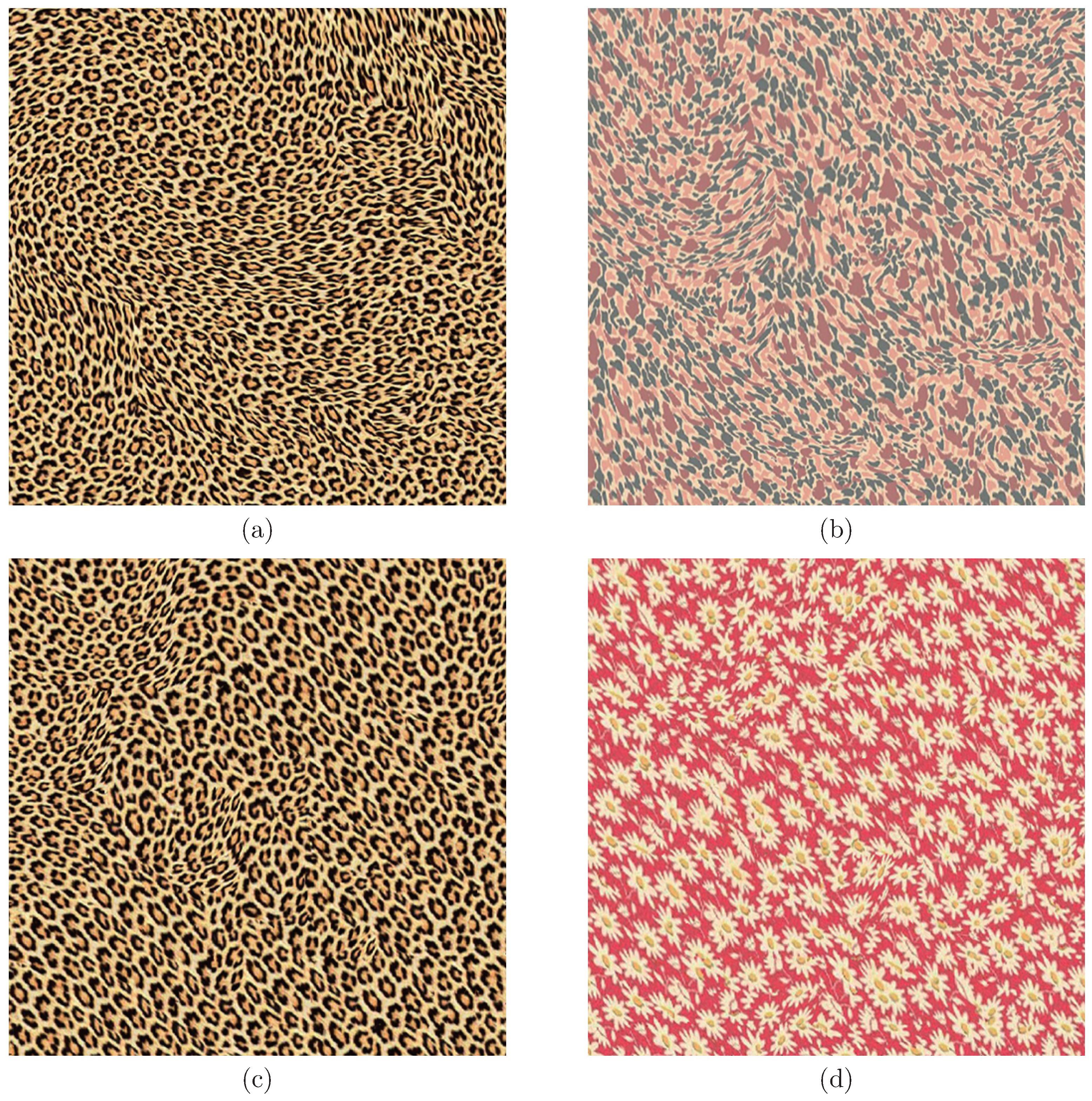
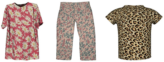
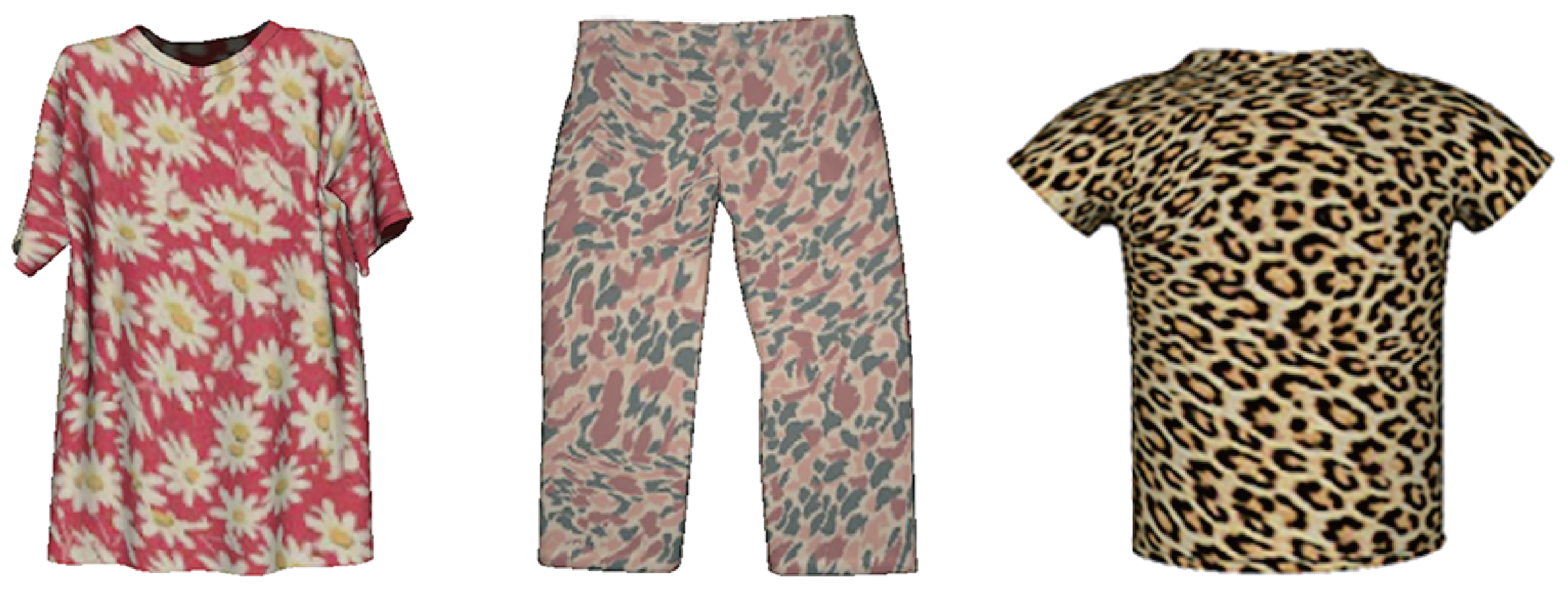
Figure 3 shows the texture samples and guiding vector fields used in this paper. Figure 4 gives comparisons of two situations: one is different texture samples be synthesized on the same vector field, the other is same texture samples be synthesized on different vector fields. We also parameterized the 3D garment models to synthesized texture domain and some results are shown in Figure 5. We can see that our method can create anisometric images which could reflect the flow of the guiding vector filed while maintain fine resolution during the whole result image. And through designing the vector field, the appearance of the result can change responsively. Furthermore, the result of our method is nearly four to nine times the resolution of previous anisometric texture synthesis approach [7].
Figure 3.
(a), (b) and (c) are sample textures, (d) and (e) are the guiding vector fields.
Figure 5.
Results on 3D garment models.
We match the adjacent blocks by measure the euler distance in the overlap, hence any discordant vector will bring a chain reaction. On the other hand, there were no strict guarantee that adjacent blocks would have smooth visual effects. In the matching stage we set constrains to the candidate location, which will narrow the range of suitable blocks. If the size of images in the warping image level is small, the matching stage may not able to pick a block that matches the adjacent blocks appropriately. The results in Figure 4 have shown some discording blocks due to this limitation.
5. Conclusion
We expand the original sample texture to a series of transformed textures called warping image stack. The transformed textures in the warping image stack are periodic with smooth deformation and the warping intensity varies with stack hierarchy, hence we can obtain distortion informations for local rotation and scaling to generate natural and anisometric textures. Our method uses a vector field to control the appearance of the texture synthesis. On one hand, the more similar two adjacent blocks are, the lower level of warping image stack will be chosen, thus the result texture can appropriately react to the intensity of the vector field. On the other hand, the location of candidate block has been restrict to have same derivative in the edge of overlap, which ensure the deformation between two adjacent blocks smooth. Various simulations have demonstrated that our method is effective in different texture images and vector fields.
There are a number of avenues for future work.
- Consider other warping methods, such as parameterizing the sample texture to curved patches.
- Extend the block size to arbitrary and take the ending location of block into account.
- Explore order-independent algorithm instead of scan-line order.
Acknowledgments
The authors would like to thank the people who supported this work for helping with the experimental design, and we would like to thank the anonymous reviewers for their valuable comments. This research is supported by the Natural Science Foundation of China (No. 61379112, 61272192). Fan Zhou is the corresponding author.
References
- Eisenacher, C.; Tapan, C.; Burley, B.; Teece, D.; Shek, A. Example-based texture synthesis on Disney’s tangled. ACM SIGGRAPH. 2010 Talks, Article No. 32, July 2010.
- Efros, A.; Leung, T. Leung, Texture synthesis by non-parametric sampling. ICCV 1999, 1033–1038. [Google Scholar]
- Wei, L. Y.; Levoy, M. Fast texture synthesis using tree-structured vector quantization. ACM SIGGRAPH 2000, 479–488. [Google Scholar]
- Ashikhmin, M. Synthesizing natural textures. Symposium on Interactive 3D Graphics, 2001; p. 217226. [Google Scholar]
- Wei, L. Y.; Levoy, M. Order-independent texture synthesis. 2003. Available online: http://graphics.stanford.edu/papers/texture-synthesis-sig03/.
- Lefebvre, S.; Hoppe, H. Parallel controllable texture synthesis. ACM Trans. Graph. 2005, 24(3), 777–786. [Google Scholar]
- Lefebvre, S.; Hoppe, H. Appearance-space texture synthesis. ACM Trans. Graph. 2006, 25(3), 541–548. [Google Scholar] [CrossRef] [Scilit]
- Efros, W. Freeman, Image quilting for texture synthesis and transfer. ACM SIGGRAPH 2001, 341–346. [Google Scholar]
- Kwatra; Schodl, A.; Essa, I.; Turk, G.; Bobick, A. Graphcut textures: Image and video synthesis using graph cuts. ACM SIGGRAPH 2003, 277–286. [Google Scholar]
- Cohen, M.; Shade, J.; Hiller, S.; Deussen, O. Wang tiles for image and texture generation. ACM SIGGRAPH 2003, 287–294. [Google Scholar]
- Gonzalez, F.; Patow, G. Continuity mapping for multi-chart textures. ACM Trans. Graph. 2009, 28(5), Article No. 109. [Google Scholar] [CrossRef] [Scilit]
- Zhang, F. L.; Lai, Y. K.; Hu, S. M. Efficient synthesis of gradient solid textures. Graph. Model. 2013, 19(3), 460–469. [Google Scholar]
- Turk, G. Texturing surfaces and geometry creation. In Proc. the ACM SIGGRAPH 2007 Course; Article No. 2, August 2007.
- Wei, L. Y.; Lefebvre, S.; Kwatra, V.; Turk, G. State of the Art in Example-based Texture Synthesis. In Eurographics, State of the art Reports; EG-STAR, March 2009. [Google Scholar]
- Praum, E.; Finkelstein, A.; Hoppe, H. Lapped textures. In Proc. the 27th Annual Conference on Computer Graphics and Interactive Techniques; 2000, pp. 465–470.
- Turk, G. Texture synthesis on surfaces. In Proc. the 28th Annual Conference on Computer Graphics and Interactive Techniques; 2001, pp. 347–354.
- Zhang, Eugene; Mischaikow, K.; Turk, G. Vector field design on surfaces. ACM Trans. Graph. 2006, 25(4), 1294–1326. [Google Scholar]
- Fisher, M.; Schroder, P.; Desbrun, M.; Hoppe, H. Design of tangent vector fields. ACM Trans. Graph. 2007, 26(3), Article No. 56. [Google Scholar] [CrossRef] [Scilit]
- Taponecco, F.; Alexa, M. Steerable texture synthesis. Eurographics Conference, 2004. [Google Scholar]


© 2015 Textile Bioengineering and Informatics Society. This article is an open access article distributed under the terms and conditions of the Creative Commons Attribution (CC BY) license (https://creativecommons.org/licenses/by/4.0/).