


Abstract
This paper focus on the requiring of Made To Measure apparel production mode according to individual types and make calibration about body measurement and production in a line. In this paper, based on the measurement principle of structured light, a laser rotating body scanning of non-contact measurement system is introduced. Firstly, the key part of this system, such as digital motor, CCD, lens, etc, is introduced and discussed. Secondly, the principle of the whole system is brought up by analyzing the theory and realization of the structured light measurement, and a 3D reconstruction mathematical model is built based on the characteristic parameter of digital motor. Lastly, some important factors related to the accuracy of this system are discussed. The point cloud data of 3D body contour is acquired successfully via data processing and data piecing together. The further processing can be done according to the raw data. The validity of the principle of this system and the feasibility of arithmetic are verified by experiments.
1. Introduction
Human body measurement is different from dimension measuring of industrial applications. The human body is flexible and complex, and which is measured in the dynamic state and in dress in most cases, and its measurement methods are no harm to health. So there are special requirements for measuring equipment of the human body. Not only in the field of medicine and clothing, anthropometric data play an important role, but also in such aspects as sports kinematics research, health prediction.
Nowadays, the theme of the apparel industry tends to made-to-measure and e-commerce, the concept of made-to-measure has become guiding strategy in the new generation of clothing supplies [1,2]. In particularly, the development of digital technology for clothing leads to the “seamless” business model, which include the use of advanced 3D body measurement system that can obtain all-round body size data in seconds, and large-scale anthropometric items, the way of made to measure by cutting according to individual body shape (made to measure, here after referred to as the MTM), the MTM automatic correction of CAD patterns, the automatic cutting on piece cutting bed, the real-time virtual trying on clothing, the clothing product data management and the clothing e-retail [3,4,5,6] and so on. The MTM becomes very popular as it can meet the personalized demands of consumers, and besides, its premise condition is the acquirement of 3D body data quickly and accurately [7,8].
Since 1990s, many countries in the world have speeded up the research of non-contact 3D body scanning system. At present, the 3D body measurement technology abroad, mainly in the Euramerican developed country, have formed a certain industrial-scale and the measurement precision, scanning speed and operability etc of their instruments have reached a very high level. The representative products abroad are discussed as follows: ① Vitus/Smart laser scanning measurement instrument of the French Lectra company. It is equipped with four light beams and there are two CCD (Charge Coupled Devices) cameras and a laser with emission level one which no harmful for human eyes in each one [9]. The volume of the scanner is 225 cm×220 cm×285 cm with standard scanning time of less than 19 seconds, vertical resolution of 0.2 mm, and horizontal resolution of 0.1 mm. About 100 human body sizes can be automatically extracted and compatible with Excel data output format. After capturing the body surface imaging, the system can create a three-dimensional images of the high precision by computer. And with ScanWorX software, 3D editing and measurement can be performed. ② TELMAT type 3D human body measurement instrument of the German Assyst Bullmer company. It has automatic decision points, automatic calibration measurement space, automatic dimension generation, automatic body shape analysis and classification, automatic importing data in CAD system, automatic pattern generation, and the whole process is not affected by the human body movement and the color of underwear. The accuracy of the data can reach ±2 mm, measuring time is 40-3000 ms, the whole process takes less than 30 s. Data formats have IV, VRML(3D)-ASCII (measure) [10]. ③ The French SYMCAD Turbo Flash/3D is Telmat 3D body scanning system, which needs darkroom operations. Human with only underwear entered the room and stood in front of the illuminated wall. The side, front and back of the human, three different positions are shot by camera and scanned to calculate, the system can produce 50-60 accurate human body sizes and its data precision can be up to ±2 mm, and measurement data can be used in apparel CAD system in combination [11]. ④ A series of scanner production is made by textile clothing technology company (TC2) in the United States production, such as 2T4, 2T4S and so on [12]. With a phase measuring surface (PMP) technology, the system principle of the scanner is chose white layered profile measurement method, using white light source to projective sine curve in the human body surface according to the principle of light emission grid on the irregular surface of human body, inducing the deformation of grid shadow, producing the pattern that presents the outline of the human body surface, and can be detected by using 4 or 6 cameras. Body measurement system based on white light phase method is relatively cost-effective, has the simple principle, accurate and reliable measuring results and short scanning processing time, so it meets the requirement of rapid response in the apparel industry currently. ⑤ WB4, WBX, ARN and FAST scanner are made by Cyberware in the United States. It used the laser scanning method, obtains the data using the triangulation method. Its principle is using laser scanning triangulation technique to obtain 3D image and get the 3D data and a color structure graph of 24 points. The original human body data format is point cloud in order arrangement, which can be converted to the output format of 3D studio, MAX, DXF, IGESl24, OBJ, PLY, SCR, VR ML by the systematic translation process. Users can take advantage of the general 3D graphics software (such as AutoCAD, 3Dmax, etc) to read the data format and something they wanted [13]. ⑥ The principle of Hamamatsu linear body scanners in the United States is the infrared source that is produced in pulses from launch lens, emit in the human body surface, collected by detector lens to obtain the original human body data. The original body data is three-dimensional point cloud data [21]. The system can gain more complete 3D human body data using less markup and its measurement range is 2 m(H)×0.6 m(D)×1 m(W), The accuracy can reach ±0.5%. ⑦ Triform, developed by the Wicks and Wilson, is the non-contact three-dimensional image capture system. It is white light scanning system, variant of the moire fringe technology based on the technology of white light. 3D shape of objects on the screen is colored point cloud that looks like pictures of objects [14]. ⑧ VOXELAN is non-contact optical 3D scanning system with security laser scanning of Hamano. The system can provide precise information and its resolution ranges from 0.8 mm overall to 0.02 mm relative reduction. ⑨ Cousette C192 infrared body scanning system is developed by Japan Hokuriku STR company. It is infrared measurement method that based on CCD, and can obtain net size of the human body in dress [15]. ⑩ Anthropometric shadow scanners -LASS in the Loughborough University, UK, make up a computerized and automated 3D measurement system based on triangulation learn. It demands subjects to stand on a platform that can rotate for 360 degree, and background light projects to the human body through the axis of a vertical plane, reads the image of light through a line of cameras and calculates the height of the human body and horizontal radius, with the measured results of 3D data in the form of cylindrical coordinate.
Even though 3D body scanning system abroad reached a very high level in precision, but they are very expensive, huge volume, complex installation, etc. These systems are usually used in researches of clothing, human science, ergonomics, etc. 3D body scanning system mainly in foreign countries and its characteristics is shown in Table 1.
Table 1.
Foreign 3D body scanning system.
Although non-contact 3D body scanning has been investigated in mainland China for over 20 years, the research on 3D body scanning technology only limited to the step of academic study and sample developing. The related researches in China are as follows: ① Li Dehua, Zhu Zhou (Huazhong University of Science and Technology) developed a 3D scanning instrument for the whole body, which used four cameras located around the human body to avoid the blocking. It also used laser line source, dual camera complementary technology and data fusion of multiple scan head to acquire the complete point cloud data of human body surface and to build a plan of exacting human measurements automatically [16]. ② Li Xiaojiu in Tianjin Polytechnic University developed a non-contact 3D body scanning system based on natural light source and single shot technology in 2001. This system can take digital pictures of the anterior and lateral part of human body, make 3D standardization, exact useful 2D human data such as length, width and thickness, which will be translated to the related 3D measurements through building mathematical model [14]. ③ Xiao Zhengyang (Dalian Polytechnic University) studied on the research of non-contact 3D body scanning technology based on digital three-dimensional cut using the binocular vision theory. The obtained images which include human feature lines by using CCD cameras and acquired 3D data of human feature lines by combining two or more images [17]. ④ Wu Liangchen in Jiaozuo Institute of Technology developed a 3D human auto measuring system based on CCD and infrared sensor technology. The system can measure the human measurements in a short time, and there is no need for the human to be naked [12]. ⑤ Liu Fu who is in Jilin University developed a human measuring system based on image processing. He acquired images which include human feature lines by using CCD cameras and acquired −3D data of human feature lines by combining two or more images. After image processing, he exacted useful 2D human data such as length, width and thickness, which will be translated to the related 3D measurements through building mathematical model [18]. ⑥ The Military Equipment Research Institute in China and Beijing Institute of Fashion Techology developed a human measuring system which used a white-light source, raster projection, and computer vision technology to achieve non-contact 3D measurement. This system has the advantages of measurement speed, high precision, and large amount of information. It can build human size statistical model immediately, and all the data can be used to CAD of clothing, to achieve the integration of body size and apparel design [19]. ⑦ The Institute of Textiles and Clothing in Hong Kong Polytechnic University developed CubiCam 3D body scanning system, which used the fixed light source technology. This system confirmed location and analysed the moire image using automated software, then exacted the major measurements to make automated jeans pattern [20]. Shu Fangfa and Liu Ye defected in a 3D raw data acquired by the two scanning heads body scanning system basing on monocular vision, proposed a preprocessing method of human point cloud [1,2].
In conclusion, there are some weakness for domestic development systems, such as large and complex structure, large amount acquirement and calculation data, tedious calibration process, poor accuracy, etc, especially its massive size makes it unable to meet the requirements of the system portable, so that it is great inconvenience to promote and use portable made-to-measure system. Therefore, they cannot be directly applied to the development of portable made-tomeasure system.
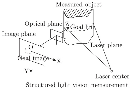
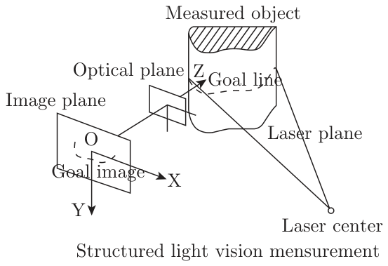
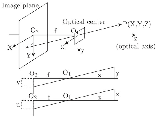
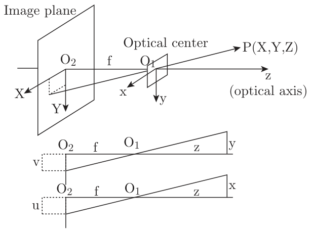
In this research, a simple hardware device is adopted to realize the non-contact rotated 3D laser human body scanning system based on linear structure-light 3D vision measurement principle. The linear structure- light 3D vision measurement principle is shown in Figure 1. Figure 2 is a simple illustration of the principle, the principle of vision measurement. It is easy to obtained the following formula, . According to the position of the object point P on image, u and v can be computed. The focus f of the lens is known. In above two formulas we could not solve the three coordinates (x,y,z) of the object point P. Another constraint must be given. So almost all the 3D position measurement system based on the vision principle uses different kind of the third constraint to solve the three coordinates. The binocular stereo vision measurement method and the structured-light measurement method are the mostly used methods.
Figure 1.
The measurement principle of linear structure-light 3D vision.
Figure 2.
The illustration of the principle of vision mesurement.
The main development goal of the system is to achieve 3D human body data. It can complete body scanning with only a few mechanical movement, fast obtain 3D data of the human body surface, and it also has the advantages of simplified equipment, less occupied areas and portable and convenient.
This paper mainly discussed the innovation of system on the measuring principle:
① The quantity of scanning heads; At least three lenses are required in human body measurement system commonly (existing) at present and lenses have certain angle to get the accurate and complete human body surface data. This project adopts two lenses to obtain obscured parts of the human body data with the method of curved surface fitting through the software technology.
② The scanning mode; Vertical scanning method is adopted in the most common human body measurement system, so the equipment takes a lot of space. This project adopts rotating scanning mode that can greatly have less occupied area.
Compared with the traditional measurement methods, the principle of the measurement can simplify equipment to reduce the hardware cost, save space, create conditions for the system toward to the retail market.
2. The Design of Measurement Hardware and Composition
The main measurement device of the scanner is the unit of two separate line light structured three-dimensional visual scanning, which are placed at the front and back of the human body. Each scanning units consisted of a line laser, a CCD camera, a digital pan tilt and tripod. The line laser and camera installed on the special mechanical components, which ensure the line laser and camera relative space position unchanged. It collectively known as the scanning head, which is the key components of this system. Scanning head installed at the plate of the top of the digital pan tilt, which controlled by computer, meanwhile the pan tilt installed at the level panel of the tripod.
The core selections of hardware realization of the system are shown as follows:
1) The laser transmitter; The system used the laser transmitter whose laser line color is red, light projection distance is greater than 4.00 m, the power is 5.00 mv, harmless to the human body, the line laser emitter is used as the light source, and selected front lighting way as the lighting way.
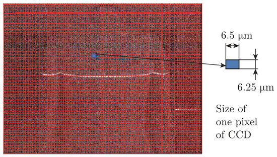
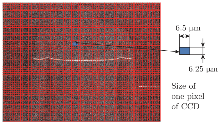
2) Camera and lens; This system used a small volume, high sensitivity, which was produced by Japan WATEC company, the type is WAT-902H3SUPREME, the black and white line array CCD camera, and whose lens is manual lens and whose focal length is 8.00 mm. The resolution of the camera is 768×576. The pixel dimension for camera is 6.50 µm(H)×6.25 µm(V). The weight of the camera is 90.00 g.
3) Pan tilt; Consider the acquisition of 3D human body surface data will apply in the field of garment, this system chose the digital pan tilt whose step length is 0.0129 degree/step, and the rotational speed can adjust. The self-developed pan tilt zoom box is controlled by a computer, through the serial port to send sixteen hexadecimal strings to the microcontroller processing instruction inside the box, by the single-chip microcomputer to decode the received data instruction. Then output the pulse signals, controlled different stepping motors to rotate corresponding angles, performed the required functions.
4) Image acquisition card; This system used the image acquisition card, whose model is dual channel USB2.0 system of U200 interface.
5) Three tripod and computer, etc; Three tripod for supporting the scanning head, that ensured the stability of the whole running process.
The main measuring hardwares of the system are simple, compact structure, small volume, easy to carry; and each weight of scanning unit not exceeding 3.0 kg, which covered an area of only 1.5 m×2.4 m.
3. The Working Principle and Mathematical Model of 3D Reconstruction
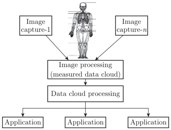
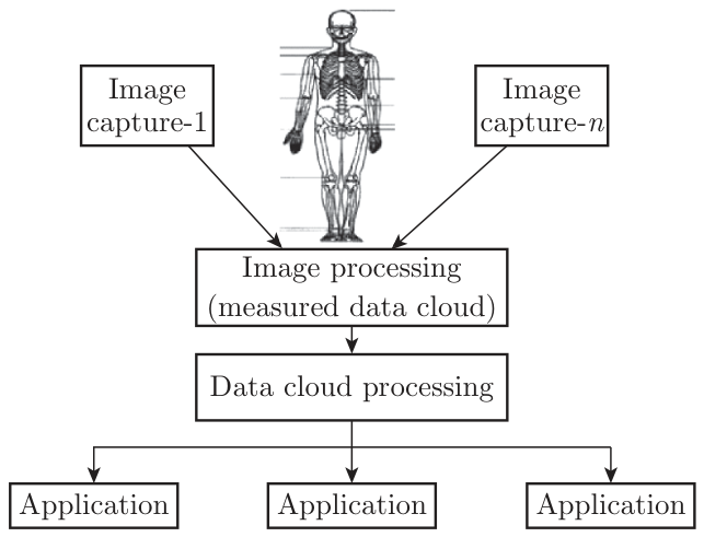
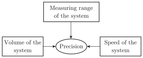
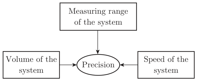
The function diagram of the laser rotating of non-contact body scanning system is shown in Figure 3. Of course, the most important consideration for a measurement system is the precision. In general, optical measurement method has higher precision. But the installation, calibration are more complicated. Precision, volume of the system, measuring range and the measuring speed are the main considerations of a vision measurement system, such as Figure 4.
Figure 3.
The function diagram of the laser rotating of non-contact body scanning system.
Figure 4.
The main considerations for the vision measurement system.
At present, most of the optical measurement system are fixed installation to guarantee the precision as we have shown in the previous pages. In practical applications, a portable measurement system could be more flexible.
Some new ideas and new algorithms used in the system:
(1) Rotation Structured-light Scanner Technique makes the volume small and measuring range large.
(2) In the structured-light measurement system, special mechanical installation make the calibration simple.
(3) The goal pixel region is limited to make the image processing time-saving.
(4) A new goal pixel searching algorithm is used make the computation effective.
(5) High-degree Rational Bezier curve is used in smoothing the measured data.
3.1. The Working Principle
The system working principle is: two scanning heads were driven by axis rotate center of pan tilt for synchronous rotation; Line laser that on the top of scanning head casting laser beam passing through a cylindrical lens in the space form a narrow laser plane. The plane bottom-up or top-down scanned the surface of the human body, and the intersected with the body surface. It was formed the light of the intersection of the body surface by modulation of the surface shape.
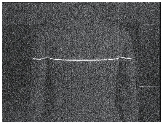
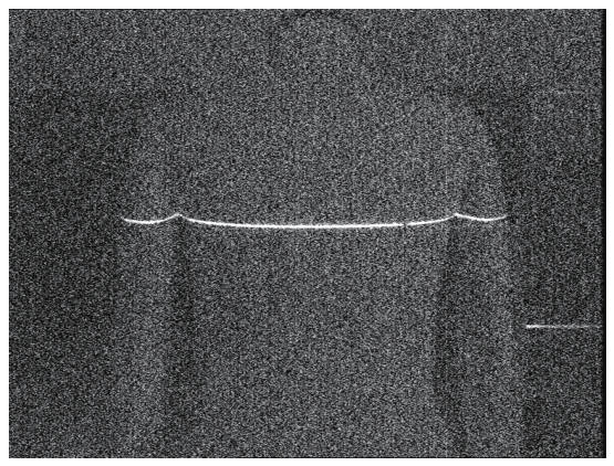
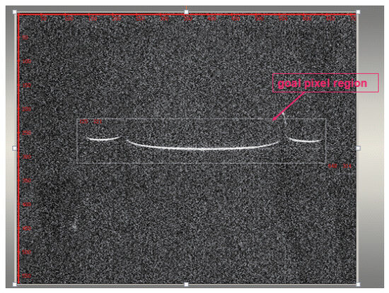
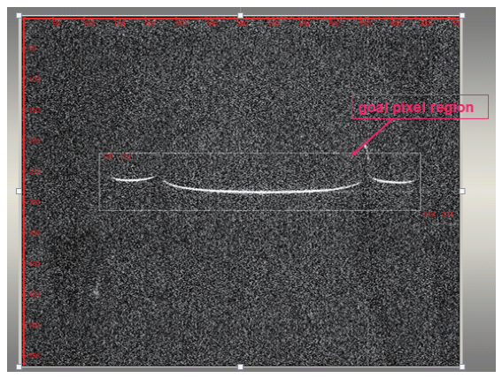
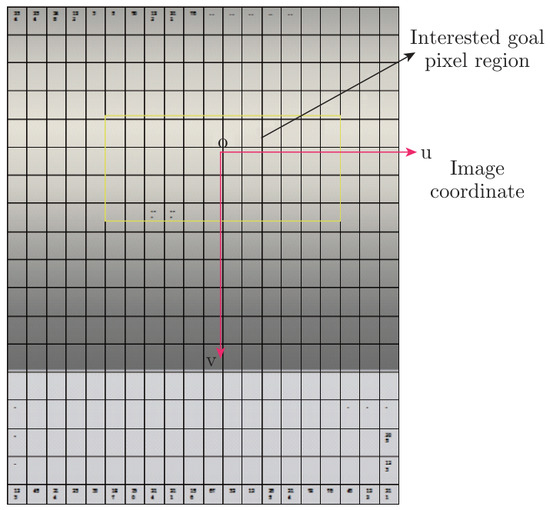
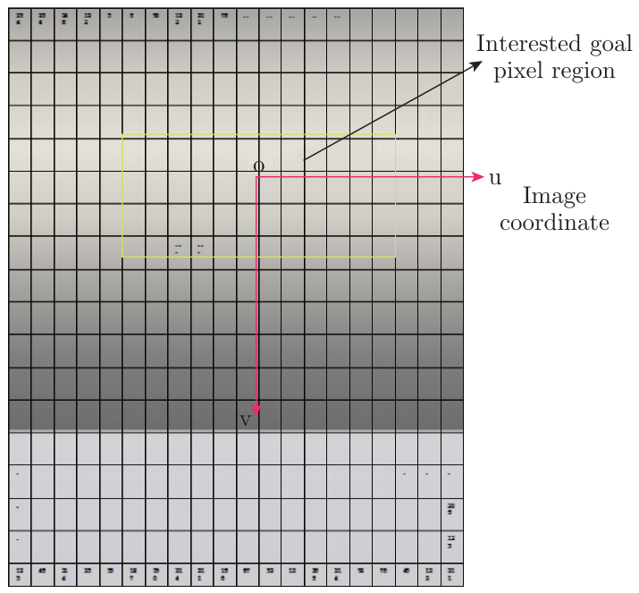
The dynamic 3D image was placed in each below the laser of the cameras every fixed time interval detection, which can obtain a series of light two-dimensional distortion images, such as Figure 5. When scanning heads rotated to different azimuth, the CCD cameras obtained twodimensional images can be transmitted to the computer for analysis, such as the extraction of human laser stripe in the goal pixel region, which is shown in Figure 6.
Figure 5.
The light two-dimensional distortion image of human body.
Figure 6.
Extraction of the human laser stripe.
The system used the establishment of the mathematical model to extract the 3D reconstruction of each light wire center location pixel coordinates, such as Figure 7, and the 3D human body coordinates were also calculated through the extraction of the laser light line of each image in the computer, such as Figure 8. Then it determined the three-dimensional human body data of the front and the back. 3D human body data point cloud can be unified into the same coordinate system according to the relative position of the relationship between two scanning units. Eventually we got the raw data point cloud on the surface of the human body, a human body surface 3D reconstruction in the form of the point cloud. The scanning time of the system mainly considered the human body during this period remains relatively motionless, minimizing the effects of motion blur. The scanning time is about 14 s.
Figure 7.
Extraction the laser stripe line in the pixel coordinates of the human body.
Figure 8.
Calculation the pixel coordinates of laser stripe line in the human body.
The so-called image processing is to process the matrix where the elements present the greyscale values. The following two facts are important during the image processing.
(1) The grey-scale values of in the goal pixels are larger (or smaller) than that of the background pixels.
(2) One pixel in the image is correspondent to a certain space in object coordinate. The precision of the position of the object depends on whether the goal pixel is seeked precisely.
3.2. The Mathematical Model of 3D Reconstruction
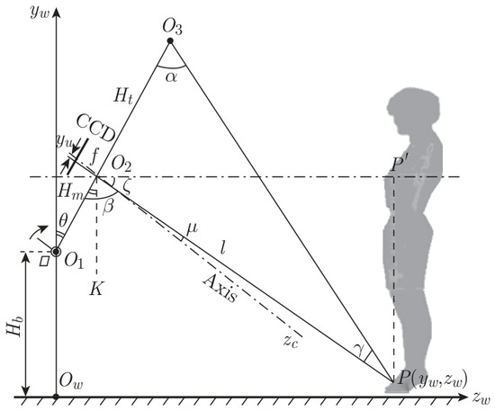
As shown in Figure 9, for the convenience of analysis, the triangular relationships between the optical center of the camera, the center of the line laser transmitter and the target point shadowed in the ywzw plane of the world coordinate.
Figure 9.
Geometry principle of the laser body scanning system projected onto the ywzw plane.
Set Ow_xwywzw as the location coordinate for the human body, which also called the world coordination. O2_xcyczc is the camera coordination. Both the location coordinate for the human body Ow_xwywzw and the camera coordination O2_xcyczc are right-handed coordinate system. The Op_xuyu is ideal image coordination. The xu axis is paralleled to the xc axis; the yu axis is parallelled to the yc axis, the zc axis perpendicular to the plane of ideal image coordination. Let O1, O2, O3 were expressed as the rotating shaft center of the pan tilt, the optical center of the camera and the center of the line laser transmitter. Light plane intersects the surface of the human body, and on the surface of the human body has a laser bright lines. Let P as the any point of the bright line, that is the target point. The P whose perspective projection point in the image plane is p. The image coordinate of the point p is (xu,yu). O3 is in the ycO2zc coordinate plane, and the light plane perpendicular to the ycO2zc coordinate plane. The intersection is O3P.
In order to establish the mathematical model of 3D reconstruction, firstly to define all the parameters which are shown as follows:
① The base height of the tripod Hb, that is the height of the rotating shaft center of the pan tilt.
② The distance between the rotating shaft center of the pan tilt and the center of the line laser transmitter O1O2, that is |O1O2| = Hm.
③ The distance between the optical center of the camera and the center of the line laser transmitter O2O3, that is |O2O3| = Ht. Ht is the baseline distance of structured light vision measuring system.
④ The rotating angle of pan tilt θ, besides, θ is the included angle between the scanning head O1O3 and the yw axis of the world coordination system. The value of θ is divided into positive and negative.
⑤ The effective focal length of the camera lens f is 8 mm.
⑥ The included angle between the laser line and the scanning heads is α, and ∠O2O3P = α.
⑦ The included angle between the camera optical axis and the scanning head is β, and β = 90◦.
According to the above hypothesis, it can be obtained in the world coordinate system, by knowing Hb, Hm, Ht, f, α, β, θ and the parameters which have clear physical meaning of describing the structure of 3D reconstruction system mathematical model, whose algorithm process is shown as follows. According to the camera imaging principle,
By knowing ∠µ + ∠β = ∠α + ∠γ, and the values of α and β, then ∠γ = ∠µ + ∠β − ∠α.
In ∆O2O3P, the , then,
Done a ray O2K, which is perpendicular to the zw axis, and whose intersection point is O2. Done a segment PP′, which is perpendicular to the yw axis, and whose intersection point is P. By knowing the value of θ, and ∠O1O2K = ∠θ, then ∠ξ = ∠θ + ∠KO2P′ − ∠β − ∠µ.
In ∆O2P′P, |O2P′| = l × cos(ξ).
Through the above formula it can be obtained:
zw = Hm × sin(θ) + l × cos(ξ)
yw = Hb + Hm × cos(θ) − l × sin(ξ)
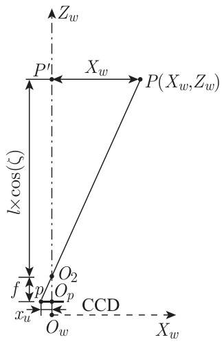
As shown in Figure 10, the triangular relationships between the optical center of the camera, the center of the line laser transmitter and the target point shadowed in the xwzw plane of the world coordinate.
Figure 10.
Geometry principle of the laser body scanning system projected onto the xwzw plane.
By the formula it has been obtained the value of O2P′, and by knowing P′P = xw,O2Op = f = 8 mm, and pOp = xu, and because ∆, then , and then
4. Error Analysis
Using Eq. (3) to Eq. (5) for three dimensional reconstruction calculation, the value of Hb, Hm and Ht can be measured directly by using a ruler, which are known as the direct parameters, by using the method of repeating measurements to reduce the errors. The values of α, β, θ and f need to be obtain indirectly, which are known as the indirect parameters, and these parameters can also be caused by 3D reconstruction errors. The value of α and β can be determined by calibration method, whose precision are also decided by the calibration. The accuracy of rotation angle of pan tilt (θ) is determined by performance of pan tilt itself. Generally speaking, the smaller the step size of pan tilt, the higher the precision of rotation angle. Because the machining error and with its own assembly errors of the camera and optical lens, the effective focal length of the camera lens (f) and the value of image coordination (xu,yu) must exist deviation. The effective focal length of the camera lens (f) and the value of image coordination (xu,yu) are corrected through the use of precision optical lens or by building the distortion model, to reduce the threedimensional reconstruction error. In short, we can through the correct selection of component and 3D reconstruction algorithm of mathematical model to reduce the errors.
5. Conclusion
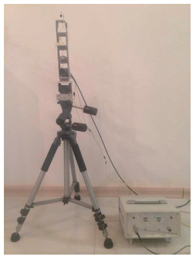
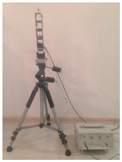
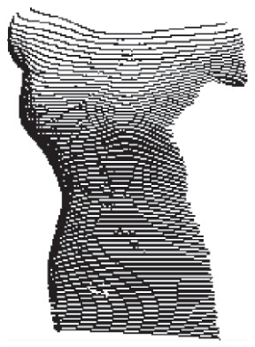
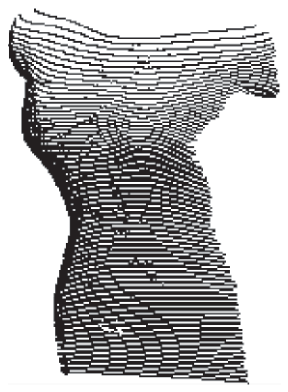
In this paper, 3D rotated vision measurement body scanning system based on linear structurelight, is at the early stage of the human body data acquisition, but the experiment results according to indoor calibration show that it has high measurement precision. Test results show that, using controller instrument developed by RS-232 serial communication, and baud rate to 9600 to communicate with personal computer, double pan tilt zoom received a control command of the time delay is only 6.7 s. Under the action of subdivision drive control mode, not only eliminated and weaken the vibration of the stepping motor, but also improved the step resolution of it. That means, in the mode of thirty-two subdivision, step angle of 0.9 degree could obtain the microstep angle of 0.028125 degree. If the stepping motor speed is set to 1600 steps/circle, then the step of pan tilt is 0.225 degree/step, and the rotation angle error of pan tilt zoom is: δθ = 1600 step/second × (6.7 µs ÷106) × 0.225 degree/step=2.412 × 10−5 degree. The value of δθ became smaller, improved the operation accuracy of the pan tilt. The controller developed by ourselves made the system running steadily and reliably, and could make double pan tilt synchronous positive and reverse rotated, and can continuous regulated the speed of rotation. Figure 11 is the real photo of the scanning system hardware. Figure 12 is the acquired images of body surface points.
Figure 11.
The real photo of the scanning system hardware.
Figure 12.
The acquired images of body surface points.
The research of 3D vision measurement rotated body scanning system based on linear structurelight lays the foundations for the development of the digital garment made-to-measure system, plays a very important role, creates conditions to clothing retail market in small and medium-sized enterprises.
References
- Shu, F. Study on Portable Apparel Customization System Based on Monocular Vision [D]; Xi’an Polytechnic University: Shaanxi, 2008. [Google Scholar]
- Liu, Y. Data Processing, Dimensions Extraction and Human Modeling Methods with the Point Cloud From a Two Scanning Heads Body Scanning System Based on Monocular Vision [D]; Xi’an Polytechnic University: Shaanxi, 2009. [Google Scholar]
- Istook, C. Automating customization of apparel. Int. J. E-Bus. Strategy Manag. 2002, 9(5), 34–41. [Google Scholar]
- Mckinnon, L.; Istook, C. Consumer acceptance of body scanning. J. Fash. Mark. Manag. 2001, 3(2), 78–89. [Google Scholar]
- Fralix, M.T.; Cary, N.C. From mass production to mass customization. J. Text. Appar. Technol. Manag. 2001, 1(2), 112–120. [Google Scholar] [CrossRef] [Scilit]
- Istook, C. Technological applications enabling mass customization. Int. J. Cloth. Sci. Technol. 2001, 21(13), 119–127. [Google Scholar]
- Chen, D.; Yu, D.; Xu, Z.; et al. Research on three views of 3D measurement on human body with line laser of vision calibration system. Comput. Meas. Control 2008, 16(9), 1249–1251. [Google Scholar]
- Fang, J.; Ren, L.; Ding, Y.; et al. A 3D body measurement method with a single camera. J. Donghua Univ. (Natural Science) 2010, 36(5), 536–540. [Google Scholar]
- Luo, S.; Zhu, S.; Sun, S. Current situation and development trend of body measurement technology. Ergonomics 2002, 8(6), 31–34. [Google Scholar]
- Xia, L. Three dimensional body measurement technology in apparel industry. Shanghai Text. Sci. Technol. 2006, 34(5), 76–77. [Google Scholar]
- Hurley, J.D.; Demers, M.H.; Wulpern, R.C. Body measurement system using white light projected patterns for mad-to-measure apparel. SPIE 1997, 3131, 212–223. [Google Scholar] [CrossRef] [Scilit]
- He, D. Research on Automatic Measuring System for 3D Human Body Size; Jiaozuo Institute of Technology, 2001; Volume 4, p. 3. [Google Scholar]
- Hamamatsu Corporation. 2002. Available online: http://usa.hamamastu.com/sys-industrial/blscanner/default.htm.
- Zhao, J. The Non-Contact Body Measurement System of Digital Image Processing and Measurement of Human Information Acquisition; Tianjin University of Technology, 2004; pp. 1–3. [Google Scholar]
- Wu, L. Basing on Three Dimensional Body Measurement Parameter Mannequin [D]; Xi’an Polytechnic University: Shaanxi, 2006; pp. 9–11. [Google Scholar]
- Zhu, Z. Research and Virtual Trying on Technology to Get the 3D Information of Human Body; Hua Zhong University of Science and Technology, 2004; pp. 12–13. [Google Scholar]
- Yuan, Y. Basing on Camera Self Calibration Technique of Non-Contact Body Measurement; Dalian Light Industry Institute, 2005; pp. 1–2. [Google Scholar]
- Di, W. The Body Measurement Based on Image Processing; Jilin University, 2006; pp. 3–4. [Google Scholar]
- Lu, X. System development of automatic measurement of human dimensions. J. Beijing Inst. Fash. Technol. 1999. [Google Scholar]
- Yu, Y. Three-dimensional body measurement and fitting garment cutting. J. Text. 1996, 6, 29–31. [Google Scholar]

© 2015 Textile Bioengineering and Informatics Society. This article is an open access article distributed under the terms and conditions of the Creative Commons Attribution (CC BY) license (https://creativecommons.org/licenses/by/4.0/).