


Abstract
Liquid flow through fibrous materials is important in a diverse range of applications. The prediction of flow through fibrous materials is influenced by a variety of factors and has been recognized as a favorite topic of research in recent years. Capillary flow through fibrous materials takes place by two subsequent processes, known as wetting and wicking. Wetting of the material is the initial process, followed by wicking or flow through its capillaries. In high temperature and high humidity conditions, wicking through a textile fabric plays a very important role in maintaining the thermo-physiological comfort of the wearer by transferring the sweat from the skin to the outside surface of clothing. Prediction of the moisture transmission properties of fibrous materials is useful to characterize clothing comfort and it helps in designing textile fabrics with specific requirements. A variety of mathematical models have been proposed in order to understand the liquid flow characteristics of textile fabrics. Flow through capillary tubes and flow through porous structures have been the two main approaches taken by researchers in order to model the capillary flow through fibrous structures. This paper reviews the relevant research in the area of liquid moisture transmission through fibrous materials, followed by experimental verification of some predictions using some of the developed equations. This experimental verification was undertaken by the authors.
1. Introduction
The behavior of liquids within porous structures has been intensively studied, both theoretically and experimentally, for many years and this is due to the important applications of these phenomena in a number of technical fields. The transport of liquids through a fibrous assembly, such as a yarn or a fabric, is caused by external forces or by capillary forces. Liquid flow through textiles is caused by fibre-liquid molecular attraction at the surface of the fibre, which is mainly determined by the surface tension and the effective capillary pore distribution and pathways [1].
Several research works have been conducted in order to characterize fabrics relatively to their liquid spreading properties and to understand the effect of fabric construction parameters on these properties. Marmur and Cohen [2] characterized porous media by analysing the kinetics of capillary penetration. Ichikawa and Satoda [3] described the interface dynamics of the capillary flow.
Wakeham and Spicer [4] showed that a good correlation existed between permeability and the inter-fibre and intra-fibre voids of a tightly woven fabric. The density and geometry of fabric pores, which can be varied according to woven fabric structure, have a significant influence on the liquid flow pattern, both in interstices and downstream [5,6].
It has been reported that the most important mechanism of fabric wicking is the motion of a liquid in the void spaces between the fibres in a yarn [7]. According to the laws of capillarity, the larger pores between yarns contribute less to the long-range motion of a liquid. It has also been concluded by Minor and Schwartz [8] that, yarn intersections act as new reservoirs and feed all branches equally. The rate of movement of a liquid is governed by the fibre arrangement in the yarns which determines capillary size and continuity [9]. The liquid moisture transmission behaviour of a textile material is measured by several methods, namely horizontal or in-plane wicking, trans-planar or transverse wicking and vertical wicking [10,11]. The effect of different textile parameters, such as yarn twist, fibre cross-sectional shape and fibre and yarn linear density on the in-plane and vertical wicking behaviour of fabrics has been experimentally studied by Das et al. [12,13]. Along with the characterisation methods, the prediction tools are of utmost importance for clothing engineering design, as they can be used to predict the behaviour of different textile structures before they are actually manufactured and tested. A number of mathematical models have been proposed to simulate the liquid transfer characteristics of textile fabrics.
2. Liquid Transmission through Fibrous Structures
The processes involved in liquid transmission through fibrous structures are wetting and wicking. Wetting is the ability of a liquid to maintain contact with a solid surface and it results from intermolecular interactions when the two are brought together. The degree of wetting or wettability is determined by the balance between adhesive and cohesive forces. Wetting is the initial process involved in liquid spreading. In this process the fibre-air interface is replaced with the fibre-liquid interface. The forces in equilibrium at the solid-liquid boundary are commonly described by the Young-Dupre equation given below [14]:
where:
γSV − γSL = γLV cosθ
γSV = Surface tension between the solid and vapour interface
γSL = Surface tension between the solid and liquid interface
γLV = Surface tension between the liquid and vapour interface
θ = Contact angle
In the case of a fibrous structure, the fibres represent the solid portion. When the liquid wets the fibres, it reaches the spaces between the fibres and the capillary flow is triggered. The capillary action is the result of adhesion and surface tension. Under the action of surface tension the surface of the liquid is held together like a membrane and so, instead of just the edges moving upward, the whole liquid surface is dragged upward. When the adhesive forces between the liquid molecules and the walls of a capillary tube are stronger than the cohesive forces, it leads to an upward turning of the meniscus along the tube which contributes to the capillary action. Wicking takes place by the spontaneous replacement of a solid–air interface with a solid–liquid interface in a capillary system [15]. In a simple case, such as wicking in a capillary tube, the area of the liquid–air interface across the capillary is very small relative to the area of the wetted capillary wall, and it does not change during wicking.
Suppose the liquid reaches inside a capillary channel of radius r and the surface tension between the liquid molecules is Γ. In this case the total capillary force (Fc) that will be acting upon the meniscus to drag the liquid upward is:
Fc = 2πrΓ
The magnitude of the capillary pressure [10] is given by the Laplace equation:
where Pc is the capillary pressure developed in a capillary tube of radius r. A difference in the capillary pressure in the pores causes the fluid to spread in the media. Hence, a liquid that does not wet the fibres cannot wick into the fabric [16]. The ability to sustain the capillary flow is known as wickability [17].
The wettability of a textile material is measured using tensiometry and goniometry methods. In the tensiometry method, the wettability of a fibre, yarn or fabric is determined by measuring the wetting force applied by the surface, when the liquid comes in contact with it. In the goniometry method, the wettability of a material is determined by measuring the contact angle between the liquid drop and the fabric surface, using an image analysis method [18]. The dynamic contact angle is used as a boundary condition for modelling problems in capillary hydrodynamics, including certain stages of the droplet impact problem. The dynamic contact angle differs appreciably from the static advancing or receding values, even at low velocities.
The wickability of a textile material is determined using different measuring methods. Depending on the direction of the liquid movement during wicking with respect to the material, the methods of wicking are divided in three categories, i.e., in-plane wicking, transverse wicking and vertical wicking.
In the case of in-plane wicking, the fabric surface stays in contact with the wetting liquid at a point, from where the liquid flows through the capillaries along the fibre axis. In this wicking process both the warp and weft threads play similar roles in the movement of the liquid. The liquid movement in this method is determined either by following the position of the liquid front (rate of liquid travel) or by gravimetric or volumetric changes. Several instruments have been developed by researchers in order to measure the in-plane wicking of fabrics. These instruments work on the siphon principle and the water uptake by the fabric sample is recorded as a function of time [19,20,21].
Transverse wicking is the transmission of water through the thickness of the fabric, i.e., perpendicular to the fabric surface. This is also referred to as demand wicking. Similarly to in-plane wicking, in this method, both sets of threads play a similar role in the liquid movement. This testing method simulates the mechanism of movement of liquid perspiration from the skin through the fabric thickness. Various test methods are reported to measure trans-planar wicking [22,23,24,25,26,27] of fibrous materials. The porous plate test is used to study transverse wicking. The apparatus for the plate test consists of a horizontal sintered glass plate, kept moist by a water supply whose height can be adjusted so as to keep the water level precisely at the upper surface of the plate and the sample is placed on top of this glass plate. The amount of water transmitted through the testing material is measured using a gravimetric method or an image analysis method.
In the vertical wicking method, water moves along the capillaries in the yarn or fabric, against the gravitational force. One end of the textile material used is in contact with the liquid reservoir and the amount of liquid wicked in the vertical direction through the sample is measured as a function of time. During vertical wicking through a fabric, the threads along which the liquid is moving, work as liquid carrying threads and the other set of threads works as transverse threads. Vertical wicking can be measured by several techniques. In the visual observation method, the movement of the liquid along the sample is observed. The testing sample touches the liquid in the perpendicular direction. A little amount of dye is added to the liquid, which can enhance the clear observation of the liquid. The movement of the liquid, in terms of height of water wicked is measured as a function of time [19,28]. Microscopic observation has also been used by some researchers [29,30]. During vertical capillary rise, the effect of gravity slows down the flow rate before equilibrium is reached.
3. Modeling of Liquid Moisture Transmission
The theoretical prediction of the liquid moisture transmission behaviour of textile materials has been attempted by several researchers for many years. The problem associated with the prediction of liquid flow through textile structures is its complex nature which involves interactive effects of different fibre, yarn and fabric parameters. Furthermore, the capillaries present in textile structures are extremely complex when compared to the conventional capillary channels. The yarn is the key factor of fabric wicking. In order to understand the wicking behaviour of textile yarns and fabrics, a variety of mathematical models have been proposed. From the review of the literatures it has been observed that the mathematical work done by different scientists on wicking through textile fabrics was mainly concentrated on the in-plane and transverse wicking behaviour. Even though the test method used for measuring vertical wicking is very widely used, most of the theoretical work is confined to yarn only. From these models it is only possible to get information about the equilibrium wicking height, rather than the complete wicking behaviour of the material. An attempt has been undertaken by the authors [31] to develop a mathematical model on vertical wicking, which can predict the complete vertical wicking profile through yarns and fabrics, and it will be discussed in the subsequent section.
3.1. In-plane Wicking through Fibrous Structures
In general, the flow through fibrous structures is considered laminar in nature. Darcy’s law [65] is used to describe a linear and slow steady state flow through a porous media, and is given by Equation 4. The rate of flow (Q) changes directly with the pressure head (∆P) and is inversely proportional to the length of the sample (L0) in the direction of flow.
where, K is the proportionality constant, known as the flow conductivity of the porous medium with respect to the fluid. K is dependent on the properties of the fluid and on the pore structure of the medium [32].
The essential problem of the theories of fluid flow through a fibrous structure is to quantify the term which represent the porous structure, i.e., the permeability. Kozeny’s equation is the most widely accepted form for permeability and is conditioned by the geometric properties of a porous medium [33]. Kozeny introduced a constant, known as the Kozeny’s constant, into the simple capillary model. The value of the Kozeny’s constant depends on the shape of the channel and the basic form of the equation has been modified by several researchers [34,35].
Iberall developed a model based on the drag theory, in which the drag forces are calculated from a random orientation of cylinders with the same diameter [31]. The model developed by Ariadurai and Potluri [36] is based on the hydraulic radius theory. They calculated the in-plane wicking through a woven textile structure as the total flow through the pores between the yarns and between the fibres. The hydraulic radius of the inter and intra yarn porous media, as well as the co-efficient of in-plane permeability within the yarns and between the yarns were calculated individually.
Zhong et al. [37] used a two-dimensional Ising model to study the in-plane fluid flow through fibrous structures under pressure. For wicking, they considered the Hamiltonian energy system and the work of surface tension. To construct the energy of the system, the work of applied pressure to the internal energy of the system and the mechanical energy were also taken into account. The internal energy of the system (E) is:
where H is the Hamiltonian energy of the system, Eγ is the work done by the interfacial tension, p is the pressure applied to the system, and V is the fluid volume.
E = H + Eγ − pV
Yu and Lee [38] have developed a simplified in-plane permeability model for textile fabrics. The model is based on rectangular unit cell geometry. They used the one-dimensional Stokes equation for the flow in the channels or gaps between fibre tows and the one dimensional Brinkman equation for flow within the fibre tows. Their model incorporates the effect of porosity change on the permeability of fibre preforms under compression. The total flow rate through the unit cell equals the sum of the flow rates through the channels and is calculated as follows:
where Q is the total flow rate, qg is the flow rate in the gaps, qhg is the flow rate in the horizontal fibre tows adjacent to the gaps, ql is the flow rate in the longitudinal fibre tows, qhl is the flow rate in the horizontal fibre tows adjacent to the longitudinal fibre tows, Kx,eff is the effective permeability in the x direction, A is the total area, µ is the viscosity, dp/dx is the pressure gradient in the x direction.
Yarlagadda and Yoganathan [39] developed a mathematical model for fluid spreading in a composite web structure. They have used the mass equation for this purpose. They have considered an analogous three-dimensional transient heat transfer model with varying thermal conductivities and heat capacities, to represent the actual phenomenon of fluid spreading in the composite web. They have used three different models in their study to predict the dynamic fluid advancement in a web section.
where, T is temperature, Cp and ρ are the specific heat and density of the liquid respectively, t is time, Kx, Ky and Kz are the thermal conductivity of the material in the corresponding directions.
Ghali et al. [40] developed a model for simulating the heat and mass transfer in fabrics during the wicking process. In a fibrous structure the pores are open channel capillaries, formed by the walls of the fibres, which are unlike a regular capillary channel [41]. The capillaries are neither cylindrical nor all of them are arranged in parallel. The size and shape of the capillaries are dependent on the size and shape of the fibres and their packing in the yarn. Fibre type, under certain circumstances, can drastically change the structure of the yarn, in turn changing the wicking properties of the fabric. For instance, changes in fibre properties when wet can significantly affect the liquid movement and retention behaviors due to fibre swelling. Yarns spun with natural fibres have irregular capillaries due to various factors such as fibre roughness, cross-sectional shape and limited length, which interrupt the flow along the length of the yarn [42]. The tortuosity of the pores also has a significant influence on the wicking process. It depends on the alignment of fibres as well as on irregularities in fibre diameter or shape along the pores [43]. Vallabh et al. [44] have developed an empirical relation between tortuosity and fiber web structural properties including porosity, fiber diameter and fiber web thickness. With an increase in the tortuosity of the pores, its wicking potential is reduced. The tortuosity in the capillary path increases with the increase in yarn twist. The density and geometry of the fabric pores, which can be varied according to woven fabric structure, have a significant influence on the liquid flow pattern, both in the interstices and downstream. Thus, porous media is characterized by analyzing the kinetics of capillary penetration. Ichikawa and Satoda [45] have described the interface dynamics of capillary flow in a horizontal tube as:
where γ is the surface tension, θ is the contact angle, din is the inner diameter of a tube, ρ is the density of the liquid, g is the gravitational acceleration, z0 is the hydrostatic height in the liquid container, µ is the viscosity, t is the time, s is the liquid column length from the inlet of the tube and m is a correction factor.
Wakeham and Spicer [46] showed that a good correlation exists between permeability and the inter-fibre and intra-fibre voids of a tightly woven fabric. It has been reported that the most important mechanism of fabric wicking is the motion of the liquid in the void spaces between the fibres in a yarn [47]. According to the laws of capillarity, the larger pores between yarns do not contribute much to the long-range motion of the liquid. It has also been shown that yarn intersections act as new reservoirs that feed all branches equally. The rate of travel of the liquid water is governed by the fibre arrangement in the yarns which controls capillary size and continuity. The wicking mechanism in yarns is the key to fabric wicking performance.
3.2. Transverse / Trans-planner Wicking through Fibrous Structures
Carnali and Kotkin [48] have theoretically determined the nature of capillarity in simple woven textiles. They have also calculated the minimum pressure differential necessary to drive a test fluid through the trans-planar pores of a plain woven monofilament mesh, using the following expression:
where, γ is the fluid surface tension, d′ is the mesh centre to centre spacing, df is the fibre diameter, αm is the angular location of the fluid meniscus on the fibre at which ∆P is maximum and θ is the contact angle.
Factors such as the surface chemistry and the surface roughness of the fibres, pore sizes, the liquid surface tension and the contact angle between the solid surface and the liquid phase have a significant effect on wetting and wettability [49]. A cross-plane permeability model for needlepunched nonwoven structures has been developed by Rawal [50]. In his work the Hagen–Poiseuille equation has been modified by incorporating the mean flow pore diameter to derive an expression for the water permeability of needle punched nonwovens based on the model of Lifshutz [51]. The final expression obtained in the model is as follows:
where is the flow perpendicular to the plane of the fibres, ρw is the density of water at 20 °C, g the acceleration due to gravity, ∆h the water head difference, tfab the fabric thickness, df the fibre diameter and ε the porosity.
Miller and Clark [52] have developed an experimental method to study the wetting and steady state liquid flow through a fabric. They have modeled the phenomenon and calculated the wet through resistance [53]. The radius of curvature (R) of the liquid meniscus has been calculated by them as follows:
The maximum pressure difference and the minimum pressure difference at the curved surface are given by the following equations successively:
where and
- where, φ is angle of occurrence of the liquid meniscus with the outer layer fibre wall, Rf is the fibre radius, x is the distance between two fibres, θ is contact angle of the liquid.
For modelling transverse wicking, difficulties arise for the calculation of the interface shape, which changes with the change in the contact line and hence the pressure difference across the interface. Bayramli and Powell [54] have developed a model for transverse impregnation of liquids into a regular hexagonally packed fibre lattice, considering the continuous and discontinuous changes in the capillary pressure as the contact line changes. The gravitational force has been neglected in these models of the transverse flow, which consider the impregnation being driven solely by capillary forces and retarded by viscous forces. Due to the change in the position of the contact line on the circular cross-section of the fibre the capillary pressure difference changes to:
where, ∆P is the pressure difference, φ is the angle of occurrence of the liquid meniscus with the outer layer fibre wall, Rf is the fibre radius, x is the distance between two fibres and θ is the contact angle of the liquid.
3.3. Vertical Wicking through Fibrous Structures
Hagen-Poiseuille law [55] uses an idealized tube structure to simulate laminar flow through a circular capillary with the following equation:
where, Q is the flow rate through the channel, µ is the viscosity of the liquid, r is the capillary radius, ∆P is the pressure gradient along the flow and h is the wetted length. The forces acting during the vertical capillary flow through a capillary channel are the upward acting capillary force and the downward acting gravimetric force.
The pressure gradient ∆P is given as:
where, ρ is the density of the liquid, m is the mass of the liquid wicked along the channel and g is the gravitational acceleration, θ is the contact angle, γLV is the liquid vapor surface tension and Pc is the capillary pressure. At the equilibrium height (hmax), ∆P is equal to zero when .
The Hagen-Poiseuille’s equation is also used for the steady state flow through a porous media. In these cases, it is used to define the pore diameter. The hydraulic diameter of the pore is considered and calculated on account of non-circularity and irregularity in the pore structure and spacing [56,57]. In the case of a non-circular capillary, r is replaced by , where DH is known as the hydraulic diameter, presented as , where Ap is the cross-sectional area of the channel and Pp is its wetted perimeter.
The capillary rise from the time of initial contact to the final equilibrium position is obtained using the Lukas-Washburn equation [58,59]:
where hmax is the maximum wicking height or equilibrium wicking height, h is the wicking height at time t and C1 is a constant equal to is viscosity of the liquid.
For low values of t, the value of h is very small comparative to hmax, hence the above equation has been approximated to establish a direct relationship between wicking height (h) and wicking time (t). This is commonly known as the Washburn equation [59]:
The Washburn equation enables the calculation of the wicking height reached through a capillary channel after a specified time t. This equation is suitable for studies of the horizontal flow, where the effect of gravity is not present, but it has limitations for the case of vertical wicking. In the latter case it is only valid for very low values of t and not for the complete wicking profile. The relationship between the liquid front position and the wicking time is given by the LukasWashburn equation (Eq. (16)). From this equation, it is expected that the capillary rise after a specified time will be higher, and therefore faster, in a medium with a larger pore size. However, in a comparative wicking study, Miller has shown that this is not always the case [60]. He found that the initial wicking through capillaries with larger diameter is faster, but is eventually overtaken with time by wicking through capillaries with smaller diameter. A larger amount of liquid mass can be retained in larger pores but the distance of liquid advancement is limited. This is explained by the Laplace equation, whereby as the radius of the capillary decreases, the pressure generated in the capillary increases, thus causing a faster flow through the capillary. When a large capillary R is connected to a small capillary A [61], the net pressure acting to move the liquid out of the large capillary into the small one is:
With an increase in the packing coefficient of the yarn, the fibres come closer to each other introducing a greater number of capillaries with smaller diameter likely to promote liquid flow. The shape and size of the fibres in an assembly change the size and geometry of the capillary spaces between the fibres.
The capillary flow in a vertical circular capillary with an axially varying radius has been described by Staples and Shaffer [62] using the following equation:
where L is the wetted length of the capillary at time t, R(L) is the radius of the capillary at the wetted length L, R(z) presents capillary radius varying in a sinusoidal way, which is given by the function in z.
where Dvis is the throat diameter and Dcap the cell diameter of the capillary, and λ is the wavelength of undulations in the vertical z-direction. Dcap is always greater than Dvis.
Weiner and Dejlova [63] proposed a model to determine the equilibrium wicking height through a yarn using the following equation:
where hmax is the equilibrium wicking height, N is the number of fibres in the yarn, Rf is the radius of a fibre, P is the percentage of liquid on the surface of the bundle (%), Q is the percentage of non-wetted fibres on the surface of a bundle (%), κ is packing coefficient of the yarn.
Combining the Laplace equation for capillarity and the Hagen-Poiseuille law for laminar flow through a pipe, Das [64] has developed a model to explain vertical wicking through yarn taking different fibre and yarn parameters into account. The factors that have been taken into consideration in this model are fibre contact angle, number of filaments in a yarn, fibre denier, fibre cross sectional shape, yarn denier and twist level. This model not only determines the equilibrium wicking height, but it also provides the complete wicking profile. A mathematical function Lambertw [65,66] has been incorporated into the model, which helps to predict the vertical wicking height at any given time, considering the gravitational effects.
where h = Wicking height,
For twisted yarn, the equivalent capillary force is:
where and
n is the number of fibres at the outer layer of the yarn, κ is the yarn packing coefficient, x is the distance between two fibres, a is the distance between nearest fibres’ axis, τ is the twist/cm, ψ is the twist angle, Ry is the yarn radius in cm.
In the case of non-circular cross-sectional shaped fibres, Rf is replaced by
where d is the fibre denier, χ is fibre the shape factor and ρf is the density of the fibre.
This model has been experimentally verified by conducting vertical wicking tests on yarns using a video metric method. The details of the yarns used are given in Table 1 and Table 2.
Table 1.
Specifications of polyester and polypropylene yarns used for wicking studies.
Table 2.
Yarn sample characterization.
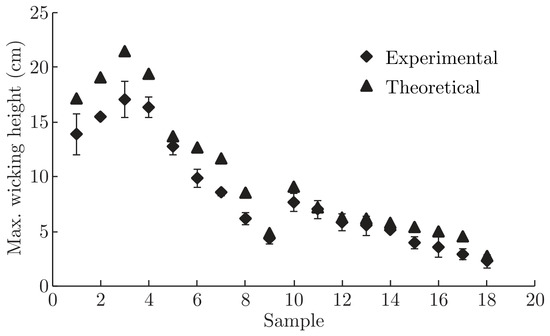
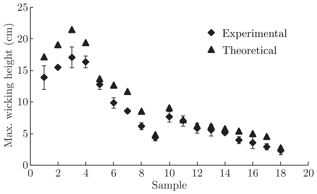
Figure 1 gives a comparison of the equilibrium wicking height values obtained from the theoretical model and those obtained experimentally.
Figure 1.
Comparison of maximum wicking height obtained from the Vertical wicking test and the theoretical model.
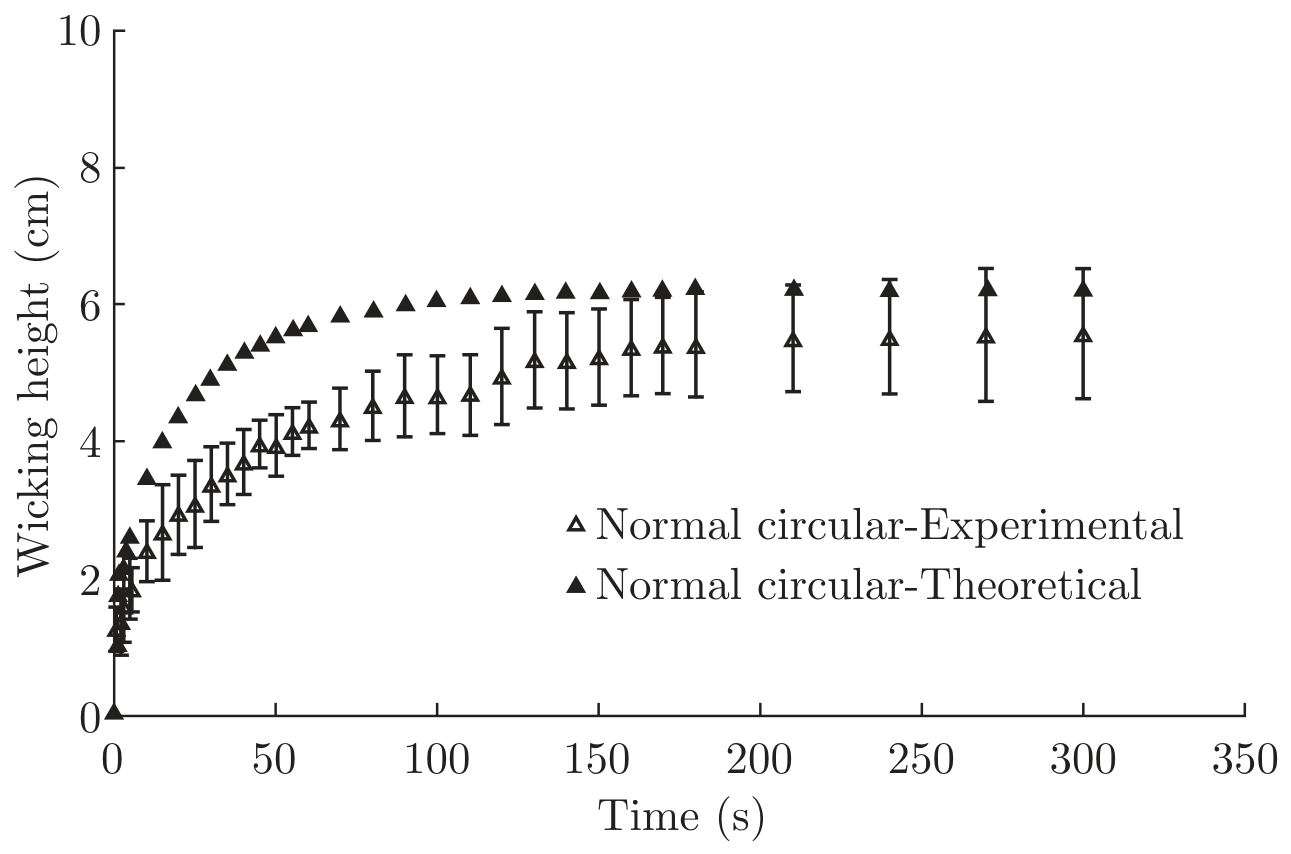
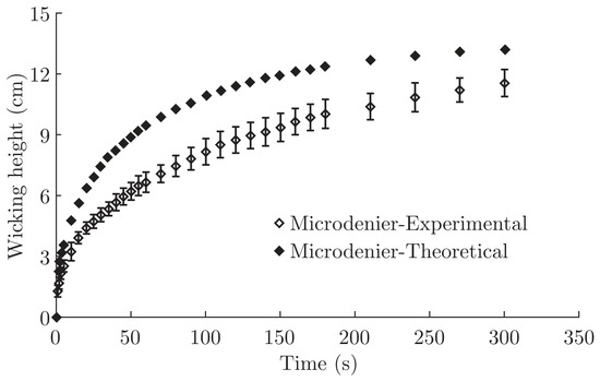
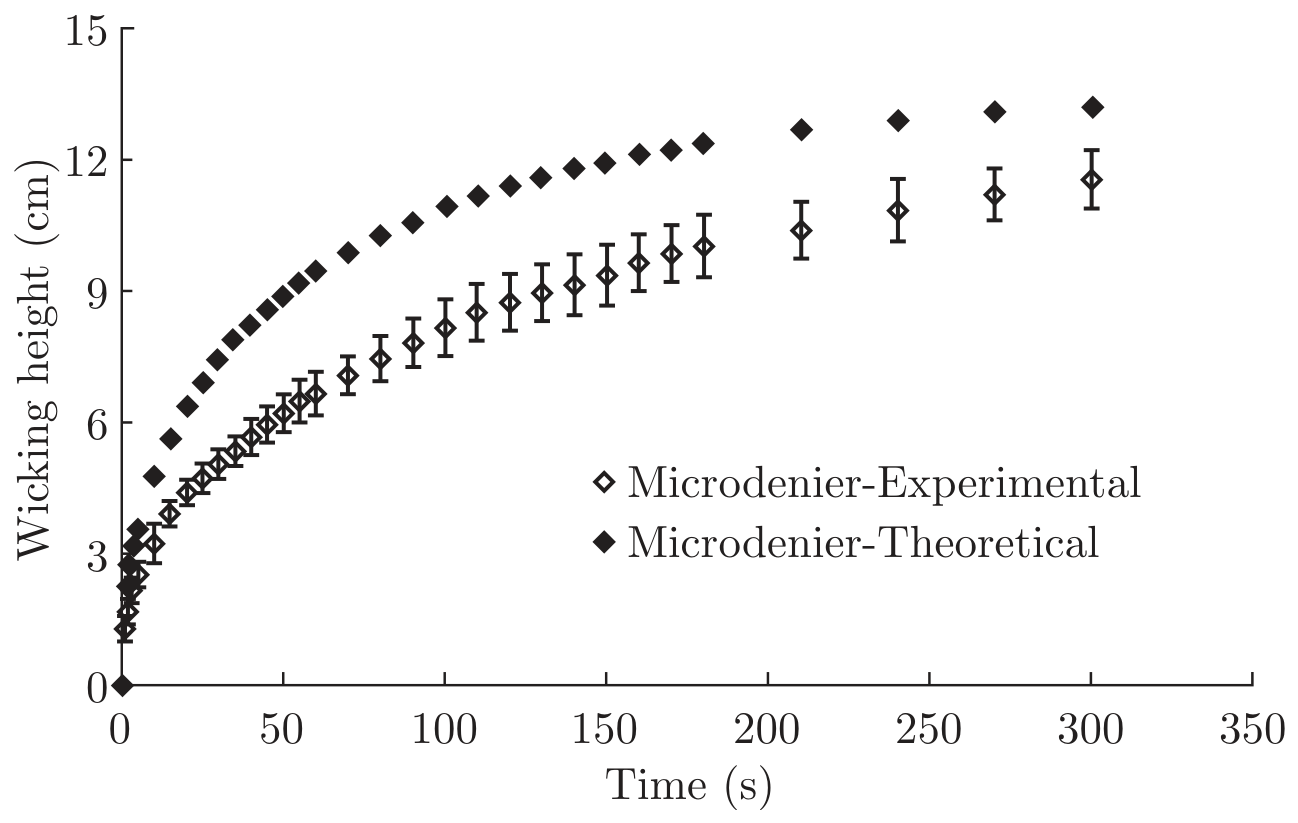
For all the above samples the vertical wicking profile (from initial to equilibrium wicking) has been measured experimentally and predicted from the theoretical model. From Figure 2 and Figure 3, it can be observed that the proposed model can predict vertical wicking through the yarn at any point in time, which follows a similar trend as found from the experimental results. The error bars given in the graphs represent the standard deviation between the measured wicking values of a sample. It has been observed that the experimental values are always at the lower side than the predicted ones. This may be attributed to the deviation of fibre packing from the idealized packing considered in the model. Moreover, during the experimental study no preventive method has been adopted to avoid liquid evaporation during wicking, which had resulted in a lower equilibrium wicking height than the actual.
Figure 2.
Comparison of theoretical and experimental wicking height through circular normal denier multifilament polyester yarn.
Figure 3.
Comparison of theoretical and experimental wicking height through circular micro denier multifilament polyester yarn.
Based on the yarn wicking model developed, an attempt has been taken by Das et al. [67], to model vertical wicking through a fabric. In order to model vertical flow through a fabric, both the vertical flow through the liquid carrying threads and the horizontal flow through the transverse threads had to be taken into account. A simplified fabric geometrical concept (inclined tube geometry = ITG) and Peirce’s Classical model for plain woven fabric [68] were used to define the fabric structure. Warp and weft linear density, fabric sett and yarn crimp were considered in modeling the fabric. For the sake of simplification only the plain woven fabric structure was considered for the mathematical calculation.
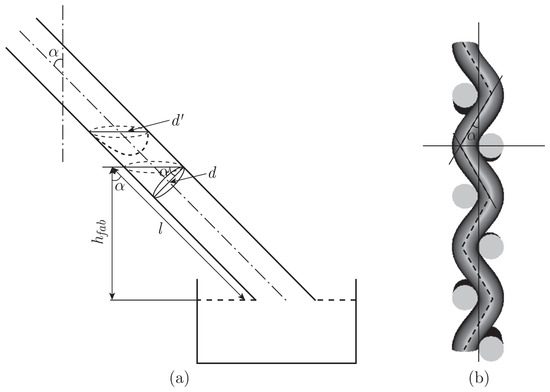
For the determination of flow both models were considered, i.e., ITG and Pierce’s. Initially the fabric was defined considering the ITG (inclined tube geometry). In this concept the capillary channel geometry through the fabric was defined considering the zig-zag path of the yarn, due to the presence of crimp, as shown in Figure 4. The angle of inclination of the tube is equal to the crimp angle of the thread. In the case of vertical wicking through the fabric along the warp direction, the warp threads are considered as the liquid carrying threads and the weft threads are the transverse threads which are in contact with the warp threads at the intersections. Therefore, at these contact points the liquid will be transferred from the warp to the weft threads and will be moved to a certain distance along the weft threads. In the case of vertical wicking through the fabric along the weft direction, the role of the threads will be reversed.
Figure 4.
Yarn position in the fabric according to the inclined tube geometry (α is the crimp angle, d is the diameter of the tube, d′ is the diameter of the liquid meniscus, hfab is the fabric wicking height and l is the wicking length along the fabric [67]).
The following equation describes the vertical movement of the liquid along the fabric:
where hfab is the fabric wicking height, k′ is the equilibrium wicking height along the fabric, t is the wicking time.
where Apwarp and Apweft are the cross-sectional area of the pore in the warp and weft directions respectively, p1 and p2 are the warp and weft yarn spacings, c1 and c2 are the warp and weft yarn crimp and α1 and α2 are the warp and weft crimp angles respectively. Ac1 and Ac2 have replaced the terms and respectively and D is the sum of the warp and weft yarn diameters.
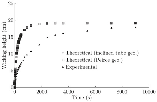
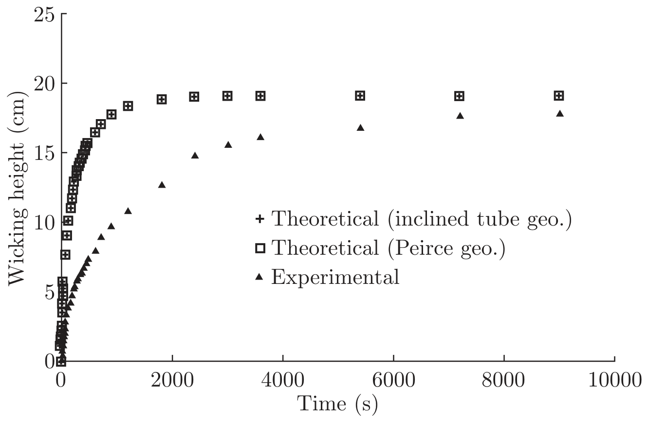
At a later stage Pierce’s fabric geometry model was considered to model vertical wicking. The predicted results obtained considering Pierce’s fabric geometry model as compared to the inclined tube geometry model do not show significant differences. In Figure 5 the values of the calculated wicking heights and the wicking values obtained from the experimental result for a polyester fabric are plotted.
Figure 5.
Comparison of the results of wicking through a polyester fabric obtained experimentally with those obtained from the theoretical models.
4. Combined Vapour and Liquid Moisture Transmission
In a humid transient condition, moisture is transported through textiles both in liquid and vapour form. Li and Zhu [69] identified that the transportation of moisture in humid transient conditions happens in three different stages. The first stage is dominated by two fast processes - water vapour diffusion and liquid water diffusion in the air filling the inter fibre voids, which can reach a new steady state condition within a fraction of a second. During this period, water vapour diffuses into the fabric due to the concentration gradient across the surfaces. Meanwhile, the liquid water starts to flow out of the regions of higher liquid content to the drier regions, driven by surface tension. During the second stage, the moisture sorption of the fibres is much slower than during the first stage, and takes a few minutes to a few hours to complete, depending on the heat transfer processes. Finally in the third stage the steady state is reached in which all modes of moisture transfer and heat transfer become steady and the coupling effect between them becomes less significant. In this condition, distributions of temperature, water vapour concentration, water content on fibre, liquid fraction volume and evaporation rate become independent of time. With liquid water evaporation, the liquid water is also drawn through the capillaries to the upper surface of the clothing. Combined liquid water and water vapour transmission along the fabric is very important in sweating condition. Liquid transport (i.e., liquid diffusion or capillary wicking) is very small compared with vapour diffusion at low moisture content, whereas at saturation, capillary wicking is the major mechanism of moisture transport. Ghali et al. [70] developed a model for simulating the heat and mass transfer in fabrics during the wicking process. The model shows that, as the water is wicked through the fabric specimen, two temperature zones are formed. Within a region the temperature gradient is small but between the regions it is significant. Unlike the temperature, the variation of the fractional saturation is continuous along the specimens. To develop the model they have taken a number of assumptions to reduce the complexity of the problem of the transport process. This model is developed considering the liquid is Newtonian in nature and the mechanical swelling and shrinkage of the fibres have not been taken into account. The numerical model is capable of simulating the temperature distribution of the fabric specimen during the wicking process and it can also predict the temperature front.
where J1 and Jv are the mass flux in liquid and vapour form, hlis the enthalpy of liquid water, hm and hc are the moisture and heat transfer coefficients, λ is the effective thermal conductivity of the water-fibre combination, Pv and Pa are saturated and ambient vapour pressure respectively, ρfab is the effective density of the fabric specimen.
The equation of conservation of moisture (considering both vapour and liquid forms) has been given by Ghali et al. [71], as follows:
where ε1 is the volume fraction of the liquid phase, ρ is the density of the liquid phase, ρv is the density of water vapour, εg is the volume fraction of the gaseous phase, ux is the absolute velocity of the liquid phase in the x direction and D″ is the coefficient of diffusion of water vapour into the fibrous medium.
5. Computational Fluid Dynamics
Computational Fluid Dynamics (CFD) is the analysis of systems involving fluid flow considering the structural complexities and the inter-relation between the processes by means of computerbased simulation. Because of the mathematical complexities involved, theoretical fluid mechanics can only solve simple problems. Experimental fluid mechanics, on the other hand, is relatively expensive, and it is often difficult to observe the details in some flow fields. Computational fluid dynamics, which has been developing very rapidly since the 1970′s, provides a tool that can simulate flow phenomena in some flow fields that cannot be solved by theoretical fluid mechanics and are difficult to study by experimentation [72]. Most of the CFD tools are based on either finite volume or finite element methods which can solve modeling equations of continuity, momentum, and energy that have been temporally and spatially discretized. In a study by Yazdchi [73], work has been done to understand the connection between microstructure (particle shape, orientation and arrangement) and macroscopic permeability/drag, using finite element simulation. Both hexagonal and square arrays of parallel cylinders perpendicular to the flow direction have been considered for the formulation. Imbibition of liquids into porous media in important engineering applications has studied by Masoodi [74]. A relatively new approach of using the single-phase flow behind a clearly-defined liquid front in a porous medium has been adopted in the work to model imbibition or wicking. The approach employs Darcy’s law in conjunction with the continuity equation to model the liquid flow behind the front. The 3-D liquid flow in the wicks was studied numerically using the finite element/control volume (FE/CV) algorithm by solving the moving boundary problem encountered in wicking. The rigid and swelling media both have been taken care in their work. Leisen et al. [75] have studied the micro flow in textiles, which occurs during different processes, i.e., chemical processing of yarn and fabrics, filtration, composite preparation, wicking in sports wear using Magnetic Resonance Imaging and Computational Fluid Dynamics. Their work provides a detailed insight into the flow phenomena in textiles. Computational Fluid Dynamics (CFD) is able to provide accurate and relevant predictions. However, as a computational method, it is always based on specific approximations and assumptions. Therefore, these tools have to be used with care and experience, as they are also prone to give misleading results if used with improper initial and boundary conditions and inappropriate functions. It is also absolutely essential that CFD results be validated by experimental techniques.
Summary
Liquid flow through fibrous materials is important in a diverse range of textile applications, including casual wear, sportswear and protective wear from their comfort point of view, textile chemical processing and cleaning, composite manufacturing - liquid transfer through preform and in many other areas. The phenomenon of liquid transfer through textile structures has been widely investigated. A number of researchers and scientists have tried to predict liquid flow through yarns, fabrics and other textile assemblies. The different types of flow occur due to the capillary action in the fibrous structure and the mathematical models available on it have been portrayed in this paper. The development of the mathematical modelling as attempted by Das et al. [67], is based on the simplified fabric geometrical model (inclined tube geometry) and the vertical and horizontal capillary flow through the inclined tubes. This model is only valid for plain woven fabric. The model can be further improved using generalized fabric geometry for any kind of weave as well as knitted fabrics. The model development can also be used for the treatment of the liquid absorption phenomenon and this will be dealt with in future work.
These mathematical models help us understand the science behind the flow and the factors involved in it. However, owing to the complicated relationships between the various factors, most of the models have been found to predict the actual flow with a large percentage of error. New tools such as computational fluid dynamics, artificial neural networks, fuzzy logic, genetic algorithms are currently being used to simulate the actual conditions. These tools can incorporate any amount of intricacies and inter-relationships between the factors involved. However, these tools have to be used with care and experience, proper initial and boundary conditions as well as appropriate functions need to be used, else the results will be misleading.
Appendix: Notation Used
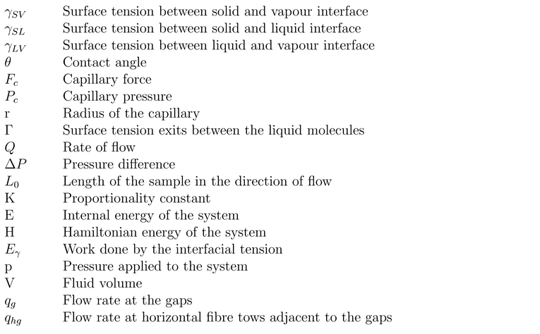 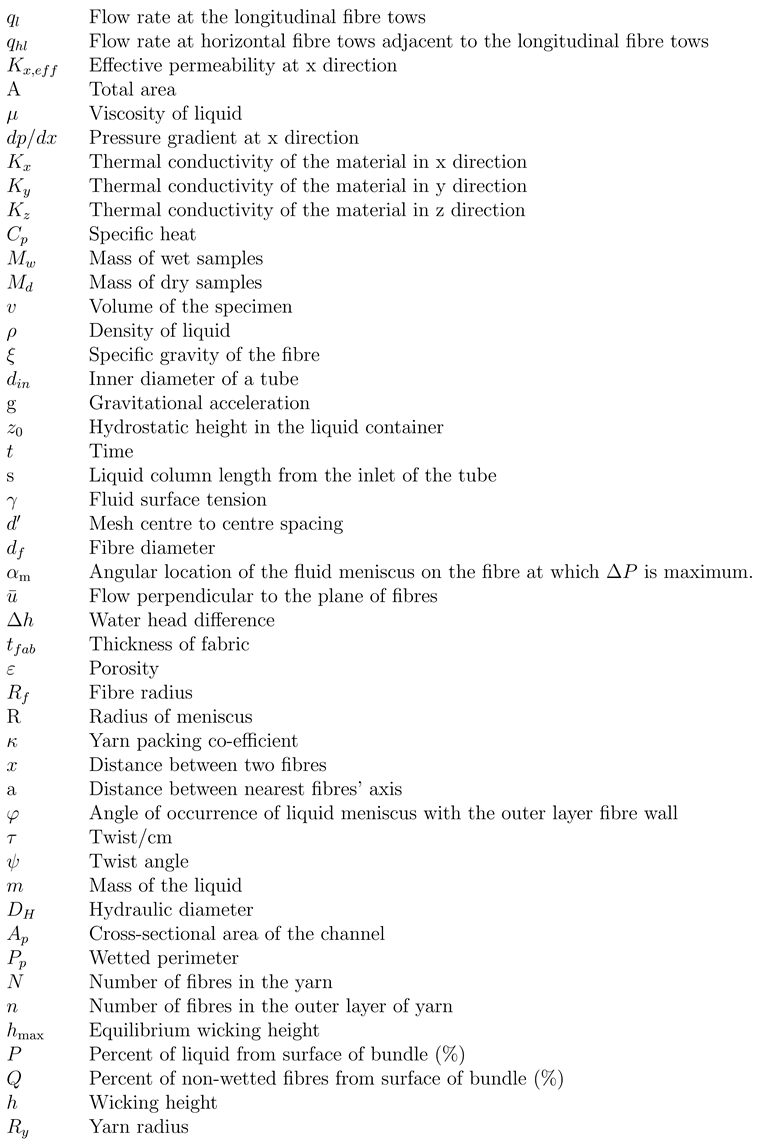 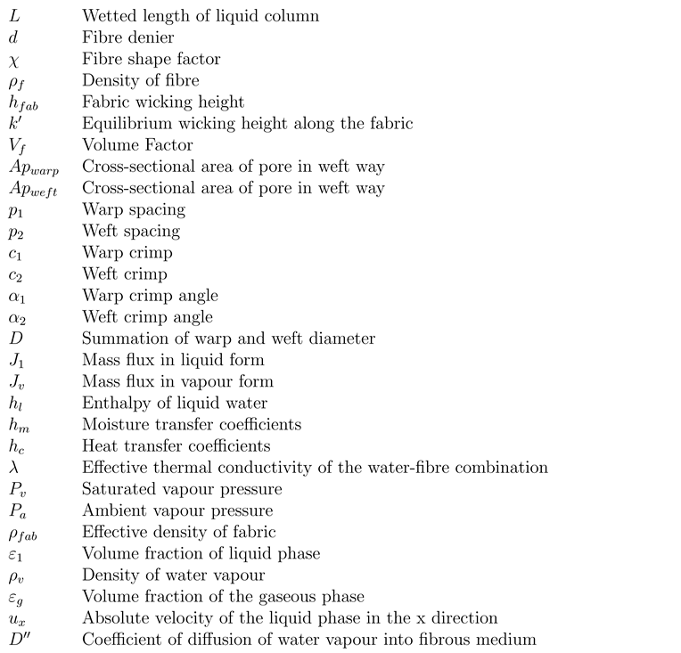 |
References
- Li, Y.; Zhu, Q. Simultaneous heat and moisture transfer with moisture sorption, condensation and capillary liquid diffusion in porous textiles. Text. Res. J. 2003, 73, 515–524. [Google Scholar] [CrossRef] [Scilit]
- Marmur, A.; Cohen, R.D. Characterization of porous media by the kinetics of liquid penetration: The vertical capillaries model. J. Coll. Int. Sc. 1997, 189, 299–304. [Google Scholar] [CrossRef] [Scilit]
- Ichikawa, N.; Satoda, Y. Interface dynamics of capillary flow in a tube under negligible gravity condition. J. Coll. Int. Sc. 1994, 162, 350–355. [Google Scholar] [CrossRef] [Scilit]
- Wakeham, H.; Spicer, N. Pore-size distribution in textiles-a study of windproof and water-resistant cotton fabrics. Text. Res. J. 1949, 19, 705–710. [Google Scholar] [CrossRef] [Scilit]
- Ming, W.; Tung, K.L.; Hwang, K.J. Fluid flow through basic weaves of monofilament filter cloth. Text. Res. J. 1996, 66, 311–323. [Google Scholar] [CrossRef] [Scilit]
- Perwuelz, A.; Mondon, P.; Caze, C. Experimental study of capillary flow in yarn. Text. Res. J. 2000, 70, 333–339. [Google Scholar] [CrossRef] [Scilit]
- Marchal, J.M. Modeling capillary flow in complex geometries. Text. Res. J. 2001, 71, 813–821. [Google Scholar] [CrossRef] [Scilit]
- Minor, F.M.; Schwartz, A.M. Pathways of capillary migration of liquids in textile assemblies. Am. Dye. Rep. 1960, 49, 37–42. [Google Scholar]
- Hollies, N.R.S.; Kaessinger, M.M.; Watson, B.S.; Bogaty, H. Water transport mechanisms in textiles materials Part II: Capillary-type penetration in yarns and fabrics. Text. Res. J. 1957, 27, 8–13. [Google Scholar] [CrossRef] [Scilit]
- Chatterjee, P.K. “Absorbency”. Elsevier Science Publishing Company, New Jersey, ISBN-13: 978-0444423771; 1985.
- Patnaik, A.; Ghosh, A.; Rengasamy, R.S.; Kothari, V.K. Wetting and wicking in fibrous materials. Text. Progress. 2006, 38. [Google Scholar] [CrossRef] [Scilit]
- Das, B.; Das, A.; Kothari, V.K.; Fangueiro, R.; Araujo, M. Effect of fibre diameter and cross-sectional shape on moisture transmission through fabrics. Fibres Polym. 2008a, 9, 225–231. [Google Scholar] [CrossRef] [Scilit]
- Das, B.; Das, A.; Kothari, V.K.; Fangueiro, R.; Araujo, M. Studies on moisture transmission properties of PV blended fabrics. J. Text. Inst. 2008b, 100, 588–597. [Google Scholar] [CrossRef] [Scilit]
- Kissa, E. Wetting and wicking. Text. Res. J. 1996, 66, 660–668. [Google Scholar] [CrossRef] [Scilit]
- Benjamin, J.M.; Igor, E.A.; Roger, D.B.; Chi, M.H. Effect of fiber orientation on fiber wetting processes. J. Coll. Int. Sc. 2004, 269, 449–458. [Google Scholar] [CrossRef] [Scilit]
- Wong, K.K.; Tao, X.M.; Yuen, C.W.M.; Yeung, K.W. Wicking properties of linen treated with low temperature server. Text. Res. J. 2001, 71, 49–56. [Google Scholar] [CrossRef] [Scilit]
- Harnett, P.R.; Mehta, P.N. A survey and comparison of laboratory test methods for measuring wicking. Text. Res. J. 1984, 54, 471–478. [Google Scholar] [CrossRef] [Scilit]
- Das, B.; Das, A.; Kothari, V.K.; Fangueiro, R.; Araujo, M. Moisture transmission through textiles. Part II: Evaluation methods and mathematical modelling. Autex Res. J. 2007, 7, 194–216. [Google Scholar]
- Chattopadhyay, R.; Chauhan, A. 2004, Wicking behavior of compact and ring spun yarns and fabrics, in one day seminar on comfort in textiles. IIT Delhi: Delhi; pp. 20–30.
- Adams, K.L.; Rebenfeld, L. In-plane flow of fluids in fabrics: Structure/flow characterization. Text. Res. J. 1987, 57, 647–654. [Google Scholar] [CrossRef] [Scilit]
- Konopka, A.; Pourdeyhimi, B. In-plane liquid distribution of nonwoven fabrics, Part I - Experimental observations. Int. Nonwovens J. 2002, Winter, 22–27. [Google Scholar] [CrossRef] [Scilit]
- Buras, E.M.; Goldthwait, C.F.; Kraemer, R.M. Measurement and theory of absorbency of cotton fabrics. Text. Res. J. 1950, 20, 239–248. [Google Scholar] [CrossRef] [Scilit]
- Harnett, P.R.; Mehta, P.N. A survey and comparison of laboratory test methods for measuring wicking. Text. Res. J. 1984, 54, 471–478. [Google Scholar] [CrossRef] [Scilit]
- Hirt, D.E.; Pourdeyhimi, R.K.; Miller, B.; Rebenfeld, L. Dynamic surface tension of hydrocarbon and fluorocarbon surfactant solutions using the maximum bubble pressure method. Coll. Surfaces. 1990, 44, 101–117. [Google Scholar] [CrossRef] [Scilit]
- Miller, B.; Tyomkin, I. Spontaneous transplaner uptake of liquids by fabric. Text. Res. J. 1984, 11, 706–712. [Google Scholar] [CrossRef] [Scilit]
- Miller, B. Experimental aspects of fiber wetting and liquid movement between fibers, in “Absorbency”, edited by P. K. Chatterjee, Elsevier, New York, USA, ISBN-13: 978-0444423771;1985:121.
- Saville, B.P. Comfort in physical testing of textiles, The Textile Institute, Woodhead Publishing Limited, Cambridge, UK, 1999: 227.
- D’Silva, A.P.; Greenhood, C.; Anand, S.C.; Holmes, D.H.; Whatmough, N. Concurrent determination of absorption and wickability of fabrics: A new test method. J. Text. Inst. 2000, 91, 383–396. [Google Scholar] [CrossRef] [Scilit]
- Sengupta, A.K.; Murthy, H.V.S. Wicking in ring spun vis-`a-vis rotor spun yarns. Text. Res. J. 1985, 55, 155–157. [Google Scholar] [CrossRef] [Scilit]
- Nyoni, A.B.; Brook, D. Wicking mechanisms in yarns-the key to fabric wicking performance. J. Text. Inst. 2006, 97, 119–128. [Google Scholar] [CrossRef] [Scilit]
- Das, B. Studies on moisture transmission through fabrics. Ph.D. Thesis, IIT Delhi, New Delhi, India, 2009. [Google Scholar]
- Adams, K.L.; Rebenfeld, L. In-plane flow of fluids in fabrics: Structure/flow characterization. Text. Res. J. 1987, 57, 647–654. [Google Scholar] [CrossRef] [Scilit]
- Scheidegger, A.E. “The physics of flow through porous media”, University of Toronto Press, Canada, 1974.
- Fowler, J.L.; Hertel, K.L. Flow of gas through porous media. J. Appl. Phys. 1940, 11, 496–502. [Google Scholar] [CrossRef] [Scilit]
- Sullivan, R.R. Further study of the flow of air through porous media. J. Appl. Phys. 1941, 12, 503–508. [Google Scholar] [CrossRef] [Scilit]
- Ariadurai, S.A.; Potluri, P.; Whyte, I.L. Modelling the in-plane pereability of woven geotextiles. Text. Res. J. 1999, 69, 345–351. [Google Scholar] [CrossRef] [Scilit]
- Zhong, W.; Ding, X.; Tang, Z.L. Analysis of Fluid Flow Through Fibrous Structures. Text. Res. J. 2002, 72, 751–755. [Google Scholar] [CrossRef] [Scilit]
- Yu, B.; Lee, L.J. A simplified in-plane permeability model for textile fabrics. Poly. Com. 2000, 21, 660–685. [Google Scholar] [CrossRef] [Scilit]
- Yarlagadda, A.P.; Yoganathan, A.P. A simplified model for fluid spreading in composite web structures. Text. Res. J. 1990, 60, 23–32. [Google Scholar] [CrossRef] [Scilit]
- Ghali, K.; Ghaddar, N.; Jones, B. Modeling of heat and moisture transport by periodic ventilation of thin cotton fibrous media. Int. J. Heat Mass Trans. 2002, 45, 3703–3714. [Google Scholar] [CrossRef] [Scilit]
- Mao, N.; Russell, S.J. Directional permeability in homogeneous nonwoven structures, Part I: The relationship between directional permeability and fibre orientation. J. Text. Inst. 2000, 91, 235258. [Google Scholar] [CrossRef] [Scilit]
- Hollies, N.R.S.; Kaessinger, M.M.; Bogaty, H. Water transport mechanisms in textile materials, Part I: The role of yarn roughness in capillary-type penetration. Text. Res. J. 1956, 26, 829–835. [Google Scholar] [CrossRef] [Scilit]
- Perwuelz, A.; Mondon, P.; Caze, C. Experimental study of capillary flow in yarn. Text. Res. J. 2000, 70, 333–339. [Google Scholar] [CrossRef] [Scilit]
- Vallabh, R.; Banks-Lee, P.; Seyam, A.F. New approach for determining tortuosity in fibrous porous media. J. Engg. Fibers Fabr. 2012, 5, 7–15. [Google Scholar]
- Ichikawa, N.; Satoda, Y. Interface dynamics of capillary flow in a tube under negligible gravity condition. J. Coll. Int. Sc. 1994, 162, 350–355. [Google Scholar] [CrossRef] [Scilit]
- Wakeham, H.; Spicer, N. Pore-size distribution in textiles-a study of windproof and water-resistant cotton fabrics. Text. Res. J. 1949, 19, 705–710. [Google Scholar] [CrossRef] [Scilit]
- Marchal, J.M. Modeling capillary flow in complex geometries. Text. Res. J. 2001, 71, 813–821. [Google Scholar] [CrossRef] [Scilit]
- Carnali, J.O.; Kotkin, C.A. Determination of the capillary nature of simple woven textiles. J. Coll. Int. Sc. 1993, 159, 319–323. [Google Scholar] [CrossRef] [Scilit]
- Mullins, B.J.; Agranovski, I.E.; Braddock, R.D.; Ho, C.M. Effect of fiber orientation on fiber wetting processes. J. Coll. Int. Sc. 2004, 269, 449–458. [Google Scholar] [CrossRef] [Scilit]
- Rawal, A. A cross-plane permeability model for needle-punched nonwoven structures. J. Text. Inst. 2006, 97, 527–532. [Google Scholar] [CrossRef] [Scilit]
- Lifshutz. On the mean flow pore size distribution of microfibre and nanofibre webs. Int. Nonwoven J. 2005, Spring, 18–24. [Google Scholar]
- Miller, B.; Clark, D.B. Liquid transport through fabrics: wetting and steady-state flow. Part I: A new experimental approach. Text. Res. J. 1978, 48, 150–155. [Google Scholar] [CrossRef] [Scilit]
- Clark, D.B.; Miller, B. Liquid transport through fabrics; wetting and steady-state flow, Part II: Fabric wetting. Text. Res. J. 1978, 48, 256–260. [Google Scholar] [CrossRef] [Scilit]
- Bayramli, E.; Powell, R.L. The normal (transverse) impregnation of liquids into axially oriented fibre bundles. J. Coll. Int. Sc. 1990, 138, 346–353. [Google Scholar] [CrossRef] [Scilit]
- Hagen, G. The flow of water in narrow cylindrical tubes. Ann. Phys. Chem. 1839, 46, 423–442. [Google Scholar]
- Millionshchikov, M.D. Turbulent flow in pipes of noncircular cross section. Atomnaya Energiya 1970, 29, 16–18. [Google Scholar] [CrossRef] [Scilit]
- Lekner, J. Viscous flow through pipes of various cross-sections. Eur. J. Phys. 2007, 28, 521–527. [Google Scholar] [CrossRef] [Scilit]
- Lukas R. Kolloid Z. 1918; 23: 15-22.
- Washburn, E.W. The dynamics of capillary flow. Phys. Rev. 1921, 17, 273. [Google Scholar] [CrossRef] [Scilit]
- Miller, B. Critical evaluation of upward wicking tests. Int. Nonwovens J. 2000, 9, 5–40. [Google Scholar] [CrossRef] [Scilit]
- Minor, F.W.; Schwartz, A.M.; Wulkow, E.A.; Buckles, L.C. Text. Res. J. 1959, 29, 931–939.
- Staples, T.L.; Shaffer, D.G. 2002, Wicking flow in irregular capillaries, Colloids and Surfaces, A: Physicochemical and Engineering Aspects, 204. pp. 239–250. [CrossRef] [Scilit]
- Wiener, J.; Dejlová, P. Wicking and wetting in textiles. Autex Res. J. 2003, 3, 64–7. [Google Scholar] [CrossRef] [Scilit]
- Das, B.; Das, A.; Kothari, V.K.; Fangueiro, R. Development of Mathematical model to predict vertical wicking, Part I: Wicking through yarn. J. Text. Inst. 2011, 102, 957–970. [Google Scholar] [CrossRef] [Scilit]
- Weisstein, E.W. “Lambert W-Function.” From MathWorld–A Wolfram Web Resource. http://mathworld.wolfram.com/LambertW-Function.html.
- Fries, N.; Dreyer, M. An analytic solution of capillary rise restrained by gravity. J. Coll. Int. Sc. 2008, 320, 259–263. [Google Scholar] [CrossRef] [Scilit]
- Das, B.; Das, A.; Kothari, V.K.; Fangueiro, R. Mathematical model to predict vertical wicking, Part II: Wicking through fabric. J. Text. Inst. 2011, 102, 971–981. [Google Scholar] [CrossRef] [Scilit]
- Peirce, F.T. The geometry of cloth structure. J. Text. Inst. 1937, 28, T45–96. [Google Scholar] [CrossRef] [Scilit]
- Li, Y.; Zhu, Q. Simultaneous heat and moisture transfer with moisture sorption, condensation and capillary liquid diffusion in porous textiles. Text. Res. J. 2003, 73, 515–524. [Google Scholar] [CrossRef] [Scilit]
- Ghali, K.; Jones, B.; Tracy, J. Modeling heat and mass transfer in fabrics. J. Int. J. Heat Mass Trans. 1995, 8, 13–21. [Google Scholar] [CrossRef] [Scilit]
- Ghali, K.; Jones, B.; Tracy, J. Experimental techniques for measuring parameters describing wetting and wicking in fabrics. J. Exp. Therm. Flu. Sc. 1994, 9, 330–336. [Google Scholar]
- Bhattacharjee, D.; Das, B. Modeling and Simulation of Heat and Mass Transfer Properties of Textile Materials, chapter in the book entitled “Modeling and Simulation in Fibrous Materials: Techniques and Applications”. ISBN 978-1-62100-116-4. Nova Science Publishers, Inc, New York, edited by A. Patanaik, 2012; p. 217-258.
- Yazdchi, K. “Micro-macro relations for flow through fibrous media”, W¨ohrmann Print Service B.V., Zutphen, The Netherlands. ISBN: 978-90-365-3414-7; 2012.
- Masoodi, R. Modeling imbibition of liquids into rigid and swelling porous media. PhD Thesis, The University of Wisconsin-Milwaukee, May 2010. [Google Scholar]
- Leisen, J.; Beckham, H.W.; Farber, P. Micro-Flow in Textiles, National Textile Center Research Briefs –Fabrication Competency: June 2007.

© 2013 Textile Bioengineering and Informatics Society. This article is an open access article distributed under the terms and conditions of the Creative Commons Attribution (CC BY) license (https://creativecommons.org/licenses/by/4.0/).