


Abstract
SnO2 hydrosol made in the lab was deposited on HTPET fibers by dip-coating method. In order to improve the deposition of the coating layer and water adsorption properties of the fiber, atmospheric plasma treatment was used as pre-treatment to enhance the interaction at the interface. Photocatalytic properties of the samples coated with SnO2 under different plasma treatments were analyzed through the degradation of methylene blue under UV-light. The morphologies and surface modulus of SnO2 coated fibers were characterized by Scanning Electronic Microscope (SEM) and Atomic Force Microscopy (AFM), respectively. The effects of plasma treatment on water adsorption behavior of the fibers were examined by contact angle measurement instrument. Tensile tests were carried out to measure and assess the mechanical properties of HTPET fiber before and after plasma treatment and photocatalysis was done. The study revealed that the photocatalytic activity of SnO2 coated HTPET fibers were enhanced due to the wettability of HTPET surfaces improved by plasma treatment and varying degrees of surface etching which benefited SnO2 adhesion on HTPET fibers. Meanwhile, the modulus of monofilament surface increased under plasma treatment but decreased after phtotcatalysis. Mechanical properties of the fibers exhibited an opposite trend. It was found that the best photocatalytic activity of HTPET fibre was obtained under 100 w power plasma treatment.
1. Introduction
Tin (IV) oxide, SnO2 (rutile type structure) is a well established n-type semiconductor with a wide band gap (Egap = 3.6 eV at 300 K), which can be widely applied in gas sensor [1,2], dye sensitized solar cell [3,4] and many catalytic processes [5,6]. The photocatalytic potential of SnO2-based composites in the removal of Methylene Blue (MB) pollutants has been reported [7]. In this regard, the preparation method of tin oxide has been drawing constant research attention [8,9,10].
These results encouraged us to further investigate the SnO2/textile material in the degradation of MB. Due to the textile materials with excellent properties (i.e. durability, flexibility and low cost) possess the possibility to use as photocatalytic substrate in special occasions [11,12]. High-tenacity Polyethylene Terephthalate (HTPET) fibers, providing high modulus and tenacity compared to conventional PET, have optimized conditions to undergo the damage during photocatalysis.
In this paper, ultrasonic hydrolysis method was adopted to produce SnO2 hydrosol. HTPET fibers were chosen as photocatalytic substrates. One of the key issues in the application of dipcoating method onto fibers is the interfacial adhesion between coated layer and substrate. Therefore, atmospheric plasma treatment, a more economical and ecological pre-treatment process, was performed to enhance the interactions in the interphase by a combination of a plasma induced increase in bonding surface such as micropitting or mechanical interlocking [13]. The primary objective of this study is to analyse the photocatalytic activity of SnO2 coated HTPET fibers. The morphologies of the SnO2 coated fibers before and after plasma treatment and photocatalysis reaction, as well as these treatment affect on the mechanical properties were characterized. In addition, the wetting behaviour of the plasma treated fibers was investigated comprehensively.
2. Experimental Details
2.1. Materials
The substrate material used in this study was commercially available High Tenacity Polyethylene Terephthalate (HTPET) fibers supplied by Korteks, Turkey. Yarn count is 110 tex and the number of filaments are 192. The chemicals used for the preparation of SnO2 sol-gel solution were tintetrachloride (Sncl4·5H2O), ammonia (NH4OH), and oxalic acid (C2H2O4·2H2O), purchased from Sinopharm (China). All the reagents were used as received.
2.2. Atmospheric Plasma Treatment and Surface Activation
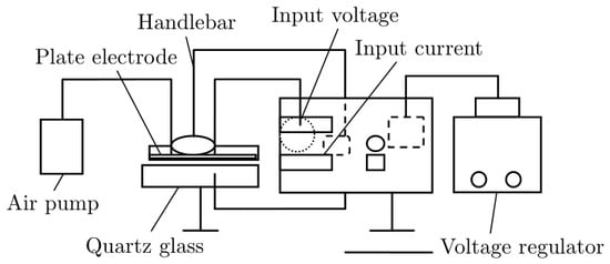
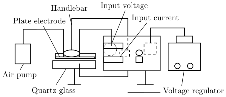
The surface of HTPET fibers were modified using non-thermal plasma generated by the Dielectric Barrier Discharge (DBD) at atmospheric pressure in air (Schematic diagram of DBD system shown as Fig. 1). The fibers were cut into about 20 cm in length and were fasted to DBD platform.
Fig. 1.
Schematic diagram of DBD system.
The atmospheric plasma was carried out according to constant speed of handlebar and controlled by means of varied values of power and time. The treatment conditions are presented in Table 1. Water contact angles of samples before and after plasma treatment were measured using a contact angle measuring system (SL200B contact angle measurement, Kono, America) employing the drop shape analysis method.
Table 1.
Parameters Plasma treatment and photocatalysis treatment.
3. SnO2 Hydrosol Synthesis and Dip-coating Deposition
The SnO2 precursor solution was prepared from tintetrachloride by dissolving SnCl4·5H2O in distilled 100 ml deionised water. Then 0.5 M solution of ammonium hydroxide (NH4OH) was added drop wise in this solution with constant stirring for 4 h at 40°C to maintain pH 1.5-2. A white precipitate of Sn(OH)4 thus obtained was washed several times with deionized water until no Cl− existence. Subsequently, saturated oxalic acid was added to the precipitate with ultrasonic agitation at 40°C to obtain a solution of pH 1.5-2. A transparent solution thus obtained and aged for 24 hrs. The resulting sol was used to fabricate thin film on HTPET fibers via dip coating technique and then dry at 80°C, the process was repeated three times.
3.1. Photocatalytic Activity
The photocatalytic efficiency of the SnO2 coated HTPET fibers were characterized with the photo-degradation of Methylene Blue (MB) under UV-light, a common practice for photocatalyst assessment. All of samples (each sample weight: 0.06 g, details compiled in Table 1) were dispersed in 50ml of methylene blue (2×10⁻⁵ M) in beakers. After those samples reached adsorption equilibrium in the dark for 8 h, the bleaching of MB solution was investigated by measuring the solution absorbance during photocatalytic reactions, at 665 nm, using the UV-Visible spectrometer (YounikeUV-2100, China) every 20 minutes. The UV light source (power 160 w) was kept 15 cm over the surface of the suspension. The degradation capacity of SnO2 coated HTPET fibers (D) was calculated by the formula1 as follows:
D = [(A0 − A)/A0] × 100%
Where A0 is the absorbency of sample before UV irradiation, A is the absorbency of sample after UV irradiation at T time.
3.2. Morphologic Characterization
Scanning electron microscopy (Quanta200, FEI, Netherlands) and atom force microscopy (CSPM5500, Benyuan, China) studies were carried out in order to analyze the surface morphology of the fibers. In AFM, tapping mode was chosen and all images were analyzed by the Imager 4.60 Software equipped with CSPM5500 AFM.
3.3. Mechanical Property
Force-distance curves of HTPET fibers were analyzed by AFM (CSPM5500, Benyuan, China). Whenever the tip was brought into proximity of a sample surface, forces between the tip and the sample lead to a deflection of the cantilever. The deflection which becomes linear gives information about substrate topography and allows direct measurements of the force between the tip and the substrate as a function of the distance separating them. These observations allow calculating the elastic modulus of single fiber surface by:

- where K is Young modulus, F is the force which follows by Hooke’s Law, Z is the distance of two bodies in contact, and Kc is the cantilever spring constant. The cantilever spring constants were measured by the resonant frequency method [14], and they were in the range of 0.13–0.19 N/m for long cantilevers (triangle shape, 200 µm long, 28 µm wide, 0.6 µm thick) and around 0.5 N/m for the short ones (triangle shape, 100 µm long, 13.5 µm wide, 0.6 µm thick).
Operating mode: Contact mode, csc11 probe, 28 KHz frequency, 0.35N/m modulus of elasticity.
Strength and elongation at break of single fibers were also measured at a gage length of 20 mm, pulling speed 20 mm/min and Pre-tension 0.5 CN by an YG001N+ single fiber electronic tensile strength tester (Nan tong Hongda, China) at ambient temperature. Monofilaments were randomly extracted from the yarns and the average values were calculated from the mean of five times measurements.
4. Results and Discussion
4.1. Wetting Behaviour
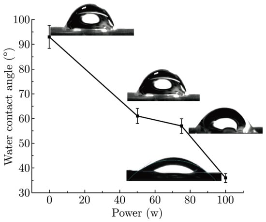
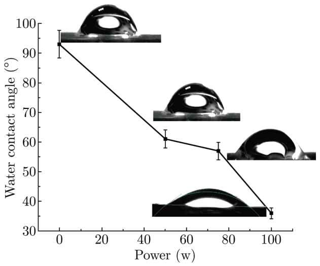
As shown in Fig. 2, the wettability of plasma treated HTPET fibers was characterized by contact angle. It can be concluded that the contact angles are considerably reduced after treatment by DBD caused plasma. The contact angle is decreased by about 30° after treatment under power 50 w for 60 s. The results also show that the contact angle reduces along with increasing plasma power under the same treatment time. This can be attributed to the grafting effect of atmospheric plasma as well as the etched fiber had a rough surface resembling a lotus-leaf.
Fig. 2.
Evolution of the water contact angle of plasma treated HTPET fiber under different treatment power.
4.2. Surface Morphology
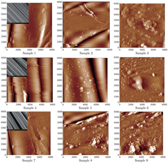
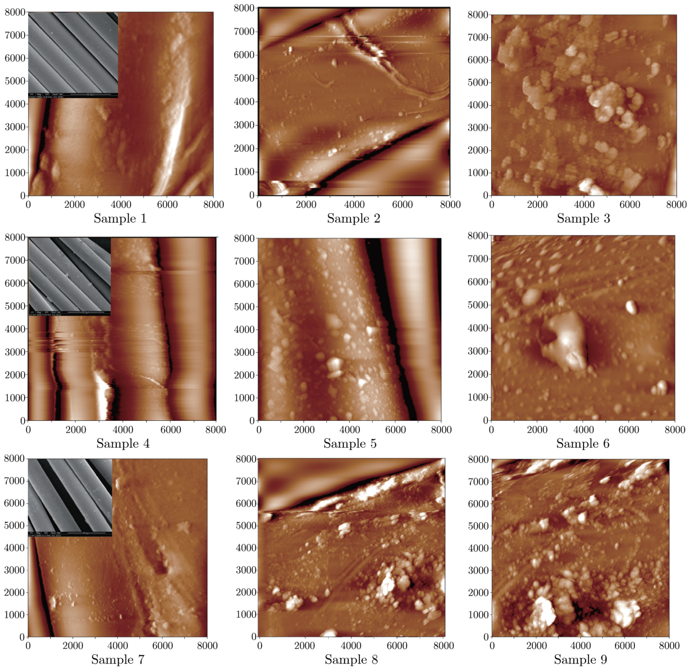
Fig. 3 contains the surfaces of untreated, plasma treated and photocatalysed fibers in the presence of different treated conditions to reveal the surface features. The AFM micrograph shows a relatively smooth surface of untreated HTPET fiber, but some streak flaws and spots can be seen in the scope of the observation (Fig. 3, sample 1). Under UV-irradiation condition, defections which caused by irradiation become a little clear (Fig. 3, sample 2). Whereas damages occur on the SnO2 coated fibers after photocatalysis (Fig. 3, sample3). Such damages also happen on all of photocatalysed fibers. It should be noted that the extent of damage corresponds with photocatalytic activity in degrading MB dyes (combined SEM images of sample 7, 8, 9 with Fig. 4), the best photocatalytic degradation efficiency leads to the worst defective morphology. Those damages may rise from OH−, owned strong oxidizing property after UV-irradiation. Simultaneously, the plasma treated fibers creates the new features on the fiber surface as shown in Fig. 3, sample 4, 5, 6. It can be clearly observed that some pitting aggregate structures form on the fiber surface. This is attributed to the etching effect of the plasma treatment, which roughens the surface of the fiber. It is also obvious that the aggregates appear to have different sizes, indicating the uneven effect of the surface etching by plasma treatment, which is mostly attributed to the preferential etching of the softer amorphous parts of the fiber in plasma treatment. It is apparent to observe that the enhancement of surface roughness is in dependence on the plasma treatment conditions. Moreover, atmospheric plasma treatments also introduce hydrophilic groups onto fibers which have been mentioned above.
Fig. 3.
AFM images of plasma treated HTPET fiber before and after photocatalysis.The insert display SEM images of HTPET fibers.
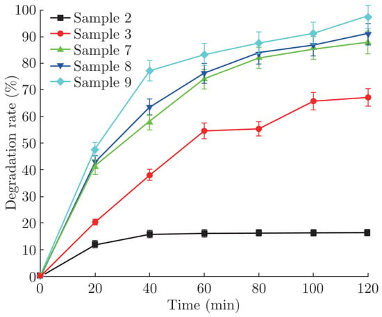
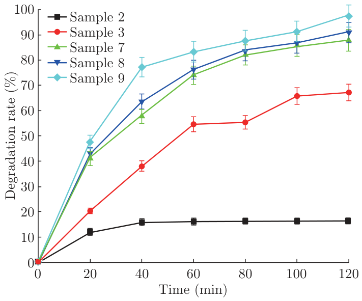
Fig. 4.
Effect of plasma treatment conditions on SnO2 coated HTPET fibers’ photocatalysis.
4.3. Photocatalytic Degradation of MB
The degradation rate of MB vs. time for HTPET fibers is shown in Fig. 4. All the SnO2 coated samples show a higher photocatalytic activity than the raw one. Typically, plasma treatments lead to a significant increase in photocatalytic degradation efficiency due to etching effect and grafting some hydrophilic groups. Nevertheless, several observations have to be pointed out. Sample 9, plasma treated power 100 w, exhibits the highest efficiency more than 95% degradation ratio. It is believed that the better coating deposited on fibers leads to a higher activity. It is reasonable to assume that the pre-treatment (work power 100 W) would be beneficial to form a compact SnO2 film on fibers, as the adhesion of the coatings to the substrate is more important, which is seen to improve significantly with plasma surface pre-treatment. At the same time, plasma treatment also improves the wettability of HTPET fibers, which should be adsorption first then degradation during photocatalysis degradation reaction, so such HTPET fibers with SnO2 coating can always degrade the dye fast at the start of reaction.
4.4. Mechanical Testing
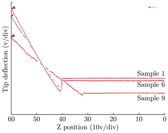
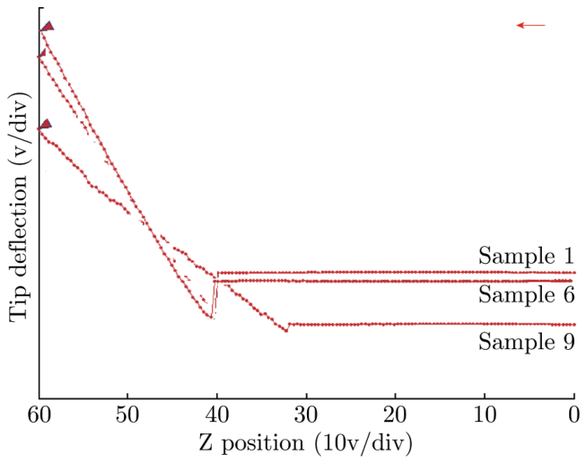
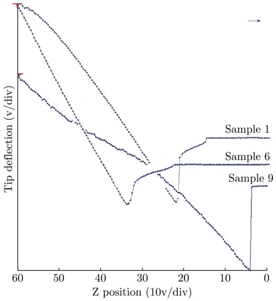
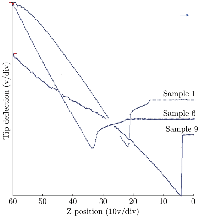
Owing to the best matching parameters of plasma and photocatalysis treatment, pre-treated sample 6 and photocatalysed sample 9 were chosen to do Force-distance curves at room temperature. Raw sample also tested as prototype model comparison (shown as Fig. 5 force-distance curves, Fig. 6 recession force-distance curves). Followed by formula 2, the elastic modulus of surface single fiber calculates in Table 2.
Fig. 5.
Force-distance curves of HTPET single fiber.
Fig. 6.
Recession force-distance curves of HTPET single fiber.
Table 2.
Modulus of HTPET fiber surface before or after photocatalysis treatment.
The force-distance curves reported here show different situations depending on the surface characteristics of HTPET fibers. In general, the deflection of cantilever matches with the modulus of surface fiber, and the larger deformation capacity means the higher modulus as well as the harder surface. Contrarily, the lower elastic modulus corresponds with softer surface of the fiber. Combined with Fig. 5, Fig. 6 and Table 2, sample 6, the optimized plasma treatment influences the stiffness of surface fiber which modulus increases by 22% than sample1 in force-distance curve. This growth trend may be attributed to etching and cleaning effects by plasma which gets rid of the softer parts leading to increase the stiffness in the testing position. However, the modulus of photocatalytic fiber reduces obviously as to the destructive effort caused by photocatalysis degradation reaction. The HTPET fiber presents uneven surface just as some residual SnO2 nanoparticles or hairiness after immersed in the MB solution for a long time, which attach to the fiber and build less stiffness after photocatalysis. It should be noted that the growth trend of modulus which is calculated from force-distance curves or force-distance curves is consistent, though the values of recession modulus are lower than the force one. When the tip convert from force angle to recession angle, the deflection of cantilever appears to be a leap in an instant, the leap on the basis of surface properties of fiber (i.e. the softer surface is apt to the higher leap) may be the explanation of this phenomenon.
Table 3 shows the mechanical properties of the HTPET fibers tested at room temperature and humidity. Theoretically, if plasma treatment conditions are well chosen, the loss in fiber strength can be reduced to the minimal value 1–2%. However, in some cases the fiber strength even increases. As expected, the obtained values are quite similar with a slightly lower strength and elongation at break of the raw HTPET fiber. It clearly identifies that the reaction only occurs on the uppermost surface of fibers and will not change the bulk properties significantly. Moreover, SnO2 coating is a kind of reinforcing material so as to overcome the defect of fiber substrate. It can be come to a conclusion that the fibers transform the soft and pliable properties into solid but crisp one after the photocatalysis treatment.
Table 3.
The mechanical properties of HTPET fibers before and after photocatalysis treatment.
5. Conclusions
The photocatalytic activity of HTPEET fibers was developed by dip coating SnO2 sol. The surface treatment of HTPET fibers was performed for improving the adhesion of the coated film onto the fiber substrates. Analysis in morphology and strength testing indicated that the uniform deposition of SnO2 on the HTPET fibers could be achieved by plasma pre-treatment with less loss in mechanical properties, and exhibited preferable photocatalytic activity. The work has exploited a new way to achieve textiles with photocatalytic activity using dip-coatings for a wide range of applications.
References
- Gong S P, Liu J Q, Xia J, et al .Gas sensing characteristics of SnO2 thin films and analyses of sensor response by the gas di®usion theory. Mat Sci Eng B 2009, 164, 85-90. [CrossRef] [Scilit]
- Im J S, Kang S C, Lee S H, et al. Improved gas sensing of electrospun carbon fibers based on pore structure, conductivity and surface modification. C arbon 2010, 4 8, 2573-2581. [CrossRef] [Scilit]
- Kumara G R R A, Murakami K, Shimomura M, et al. Electrochemical impedance and X-ray photoelectron spectroscopic analysis of dye-sensitized liquid electrolyte based SnO2/ZnO solar cell. J Photoch Photobio A 2010, 215, 1-10. [CrossRef] [Scilit]
- Yanagida S. Recent research progress of dye-sensitized solar cells in Japan. C. R. Chimie 2005, 24, 2605-2613.
- Fassier M, Chouard N, Peyratout C S, et al. Photocatalytic activity of oxide coatings on fired clay substrates. J Eur Ceram Soc 2009, 29, 565-570. [CrossRef] [Scilit]
- Wei T Y, Kuo C Y, Hsu Y J, et al. Tin oxide nanocrystals embedded in silica aerogel: Photoluminescence and photocatalysis. Micropor Mesopor Mat 2008, 112, 580-588. [CrossRef] [Scilit]
- Adamf F, Appaturi J N, Thankappan R, et al. Silica{tin nanotubes prepared from rice husk ash by sol{gel method: Characterization and its photocatalytic activity. Appl Surf Sci 2010, 257, 811-816. [CrossRef] [Scilit]
- Wang Q Q, Lin B Z, Xu B H, et al. Preparation and photocatalytic properties of mesoporous SnO2-hexaniobate layered nanocomposite. Micropor Mesopor Mat 2010, 130, 344-351. [CrossRef] [Scilit]
- Coelho M G, Delima G M, Augusti R, et al. New materials for photocatalytic degradation of Indigo Carmine—Synthesis, characterization and catalytic experiments of nanometric tin dioxide-based composites. Appl Catal B: Environ 2010, 96, 67-71. [CrossRef] [Scilit]
- Dvininov E, Ignata M, Barvinschib P, et al. New SnO2/MgAl-layered double hydroxide composites as photocatalysts for cationic dyes bleaching]. J Hazrd Mater 2010, 177, 150-158. [CrossRef] [Scilit] [PubMed]
- Sanaee Z, Mohajerzadeh S, Zand K, et al. Improved impermeability of PET substrates using oxygen and hydrogen plasma.Vacuum 2010, 85, 290-296. [CrossRef] [Scilit]
- Huang F L, Wei Q F, Wang X Q, et al. Dynamic contact angles and morphology of PP fibres treated with plasma. Polym Test 2006, 25, 22-27. [CrossRef] [Scilit]
- Vesel A, Junkar I, Cvelbar U, et al.Surface modification of polyester by oxygen and nitrogen-plasma treatment. Surface modification of polyester 2008, 40, 1444-1453. [CrossRef] [Scilit]
- Ferrari L, Kaufmann J, Winnefeld F, et al. Interaction of cement model systems with superplasticizers investigated by atomic force microscopy, zeta potential, and adsorption measurements. J Colloid Interf Sci 2010, 347, 15-24. [CrossRef] [Scilit] [PubMed]

© 2011 Textile Bioengineering and Informatics Society. This article is an open access article distributed under the terms and conditions of the Creative Commons Attribution (CC BY) license (https://creativecommons.org/licenses/by/4.0/).