


Abstract
This paper explores the elastic coefficient of sponge material in different functional areas and functional zones of the bra mold cup to improve the accuracy of parameter setting in the finite element modeling of the bra mold cup, reduce the error of simulation experiment results, and provide more theoretical basis and data reference for functional research direction in the design and production process of the bra mold cup. In this paper, three converging bra mold cups of the same style and size are selected as samples, and the mold cups are divided into three measuring areas according to functional zones. Eight measuring points are selected, and micrometer and air bag contact pressure measuring system are used to measure the wearing pressure of each measuring point and the corresponding pressure of each measuring point when compressed every 0.2 mm. Excel software was used for linear fitting of data to obtain the range of elastic coefficients and elastic distribution of different functional regions of the bra cup. At the same time, this method can also be used to analyze the wearing pressure and elastic distribution of other types of bra mold cups, providing more research reference direction and technical basis for the design and production of bra molds cups.
1. Introduction
In recent years, among bra products, mold cup bra is gradually favored by the public for its smooth and seamless inner surface of the cup, which provides good wearing comfort. At the same time, its unique molding technology improves the production efficiency of mold cup bra and reduces the traditional sewing cost, thus becoming the most favored product among consumers and underwear enterprises [1,2]. Because the bra mold cup is comfortable and close, smooth and straight surface avoids the skin damage caused by the seams between fabrics, and plays a better role in shaping and supporting the breasts, the mold cup becomes the most important part in all the details of the whole bra [3,4]. Although some progress and achievements have been made in the research of the bra cup at home and abroad, most of the research is limited to the digital simulation fitting and pressure distribution of the bra cup, and the division of different functional areas and the elastic distribution of the bra cup are still unclear. The division of different functional areas of the mold cup is to provide a foothold for the modeling and design of the mold cup. At the same time, the study of elastic distribution of mold cup is to provide data and technical reference for the design and production of mold cup and the setting of parameters of finite element simulation.
Wang YP, Chi L, etc. made an objective description of the pressure size and distribution of women’s corsets under the condition of daily dressing [5,6]. The biomechanical model of the threedimensional female human body developed by Yi L et al. can simulate the interaction between the bra and the breast as well as the pressure generated by the bra when a woman is wearing a bra [7]. By dividing the two-dimensional bra template into different functional areas, Lin Mu et al. can generate breast movement posture on the virtual model [8]. The above research only involves the pressure distribution and template area division of the bra, while the research on the functional zoning and elastic distribution of the mold cup is still unclear, and the research results have limitations for the reference direction of the design and production of the mold cup.
Chang-Lin Zhu et al. established a simulation model using finite element method to simulate women wearing typical compressed sports bras and obtained dynamic pressure changes during the wearing of sports bras. However, when it comes to the material of sports bra cups, the material parameters of sports bras are set only by obtaining the elastic modulus and Poisson’s ratio of the fabric through stretching experiments [9]. Sun Y, Xu YY, etc. used finite element analysis software to establish a finite element fitting model suitable for analysis, and completed the digital simulation of the fitting between the mold cup and the upper body of the human body [10,11]. However, the parameters of the mold cup material in the study are set to the traditional definition on the physical properties of the mold cup sponge, which is quite different from reality. The mold cup is made of a polyurethane sponge and patch. The elastic deformation capacity of the mold cup is also different depending on the sponge density, type of patch, and manufacturing process [12]. In the finite element simulation experiment of wearing the bra mold cup, the physical properties that are not completely close to the actual mold cup will lead to a large error between the simulation result and the reality, which will affect the research results. Therefore, it is particularly necessary to carry out functional zoning of the bra mold cup and study the elastic coefficient of each zone.
Therefore, this paper will analyze the elastic distribution of each functional area of the bra mold cup through the wearing pressure and elastic compression test, and obtain the range of elastic coefficient of each measurement area.
2. Wearing Pressure and Elastic Compression Experiment of Bra Mold Cup
2.1. Experimental Subjects
There are mainly “70A, 70B, 75C, 75A, 75B, 75C, 80A, 80B, 80C, others” about the mold cup bra sizes in the domestic and foreign markets. The wearing styles of mold cup bras are mainly concentrated in “full cup, 1/2 cup, 3/4 cup” and so on. According to the questionnaire analysis, the percentage of people wearing 75B bras is the highest. The majority of respondents believe that the 3/4 cup structure has a better adjustment effect on the chest. They are more inclined to choose this cup type [13]. In addition, the thickness of the mold cup bra is generally 3 mm-22 mm. When the thickness of the mold cup is about 15 mm, the volume of the mold cup is moderate, and it has a good gathering and lifting effect [14].
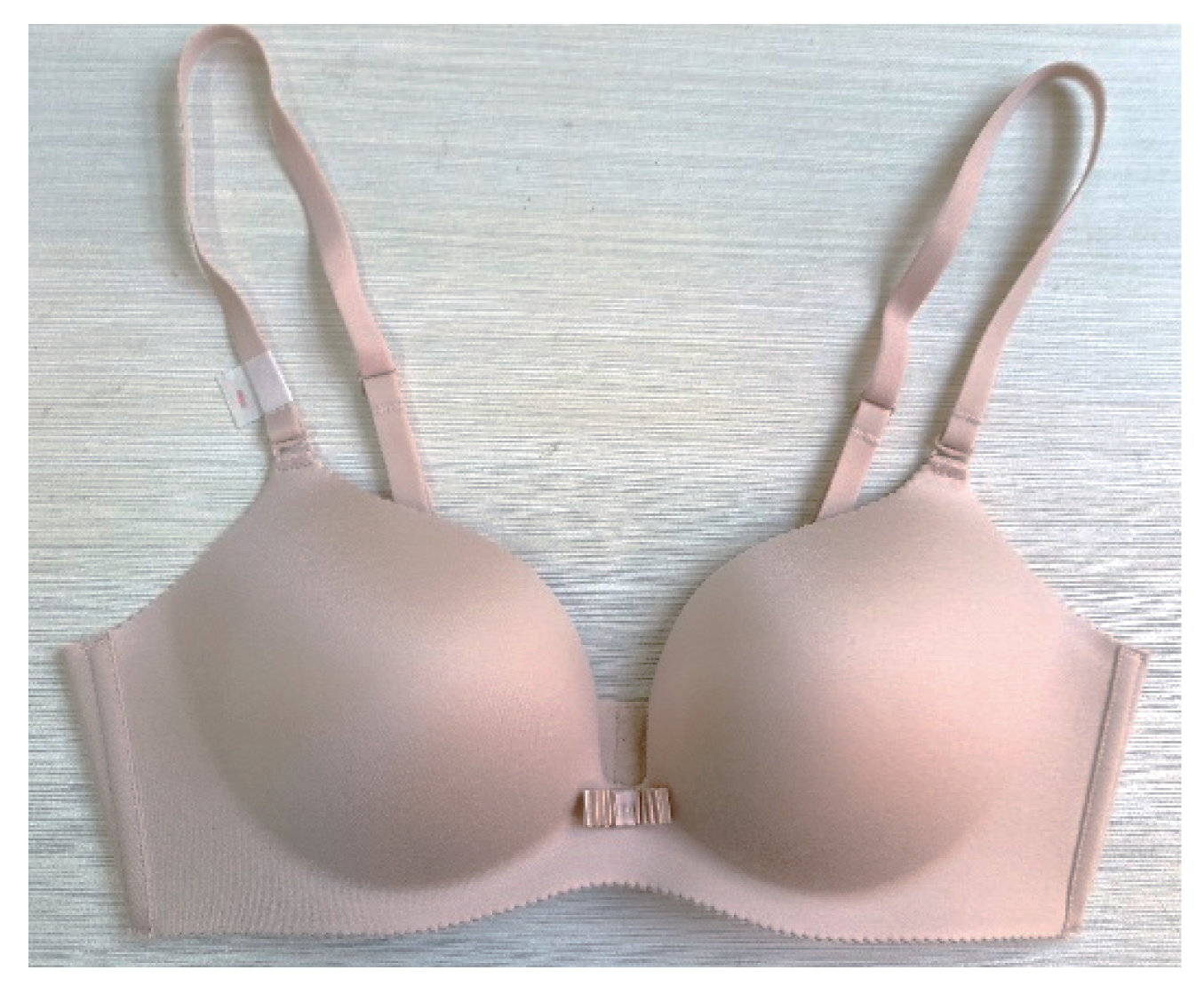
Combined with the sales of the most common basic model cup bras and underwear brands on the market, three of the same models were selected for the clothing experimentation. All of the bras were 3/4 push-up model cup bras without steel rings, with a size of 75B. The maximum thickness of the cups is 12 mm, designated bra1, bra2, and bra3 for the three mold cup bras.
Figure 1.
Experimental cup bra.
2.2. Experimental Instruments
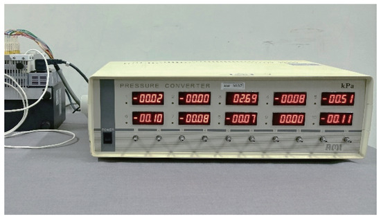
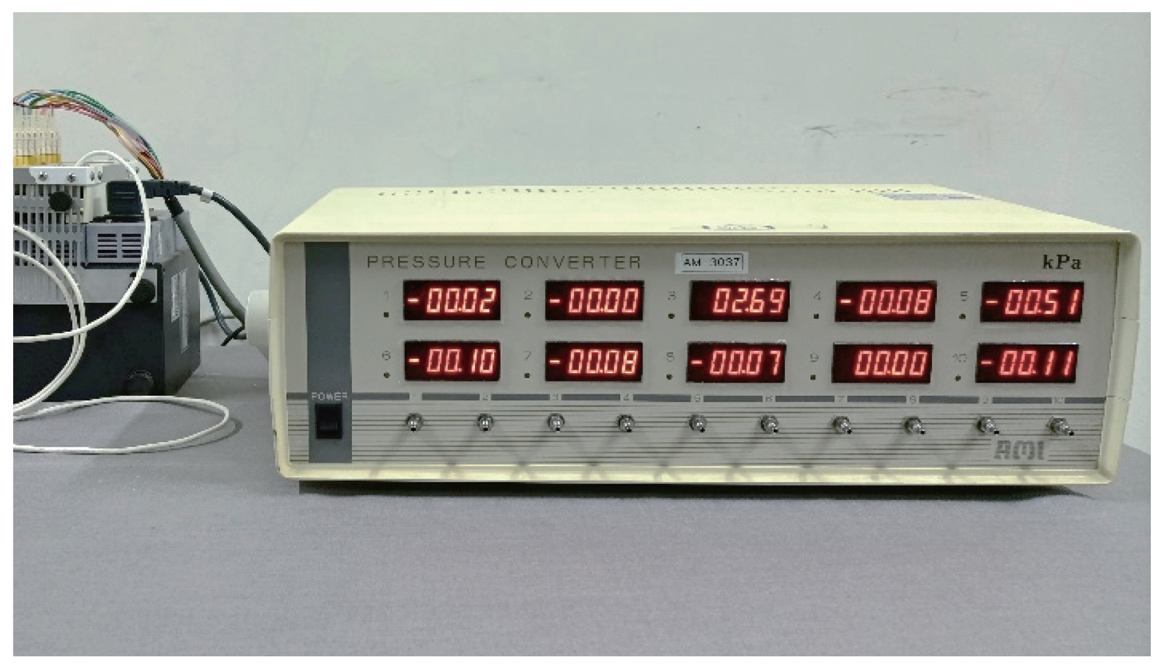
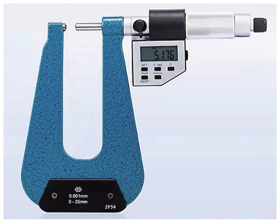
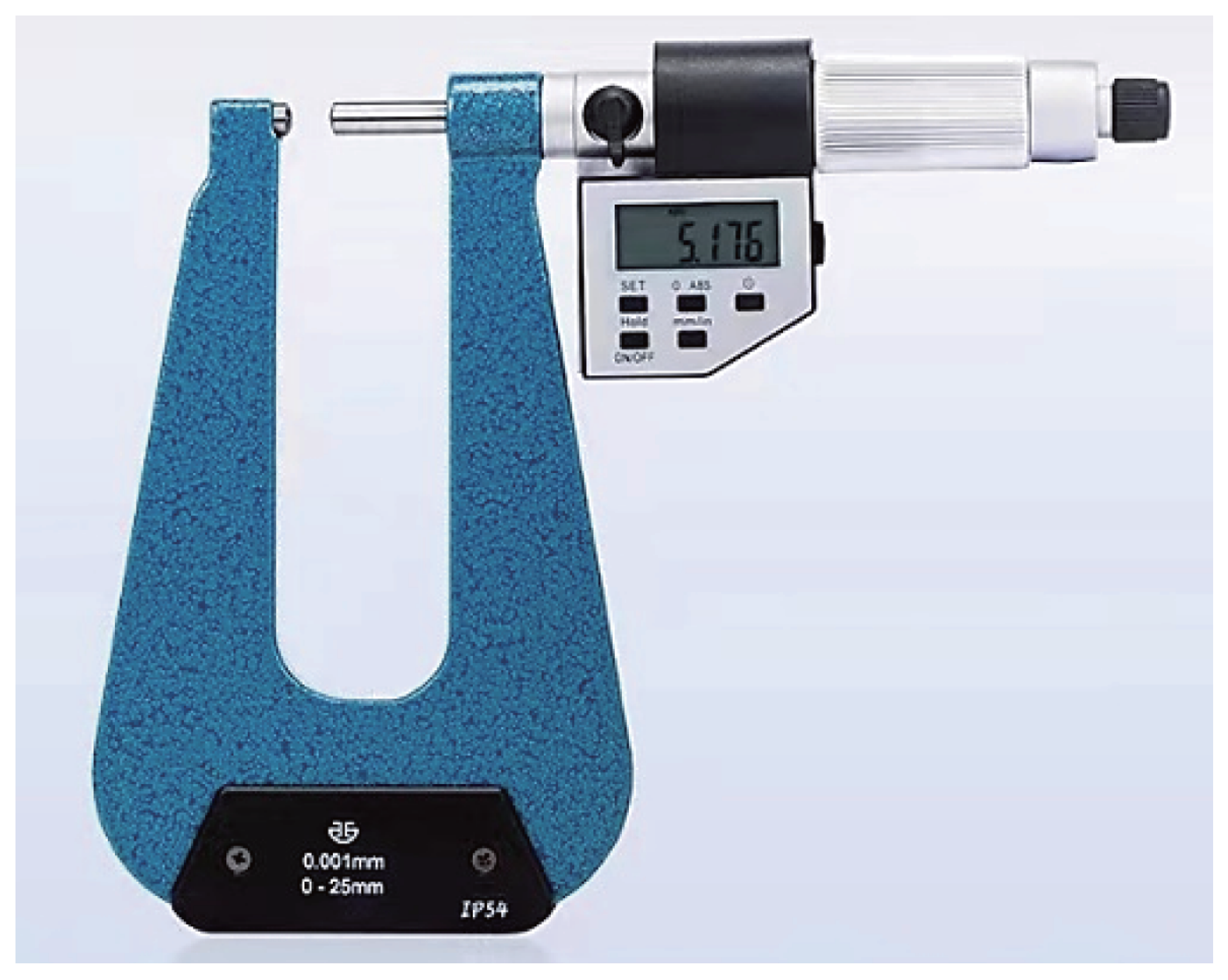
The experimental instruments are a balloon-type contact pressure measuring system and a micrometer. The pressure test instrument is AMI 3037-10 airbag contact pressure measurement system developed by AMI Techno Co., Ltd. in Japan. The system consists of a sensor and a pressure converter, of which the pressure sensor is an airbag with a diameter of about 20 mm and a thickness of 0.035 cm. The airbag pressure measurement system mainly includes airbag sensor, main receiving unit, calibrator, data collection device and supporting airbag device. The basic principle is to fill the tiny pressure-sensitive parts with a certain amount of gas and paste them on the part to be measured. The change in pressure was detected as a change in voltage. Electronic spiral micrometer (micrometer) selected from China Qinghai measuring tool Cutting tool Co., LTD bow depth 150 mm digital display micrometer, the larger bow depth can ensure that the mold cup experiment enough measuring space, measuring accuracy of 0.001 mm, range of 0-25 mm. The length of the measured object can be directly displayed on the display screen by turning the screw handle. Airbag contact pressure measurement system and electronic spiral micrometer are shown in Figure 2 and Figure 3.
Figure 2.
AMI 3037-10 airbag contact pressure measurement system.
Figure 3.
Electronic spiral micrometer.
2.3. Selection of Measuring Points
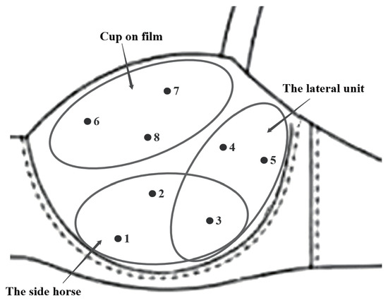
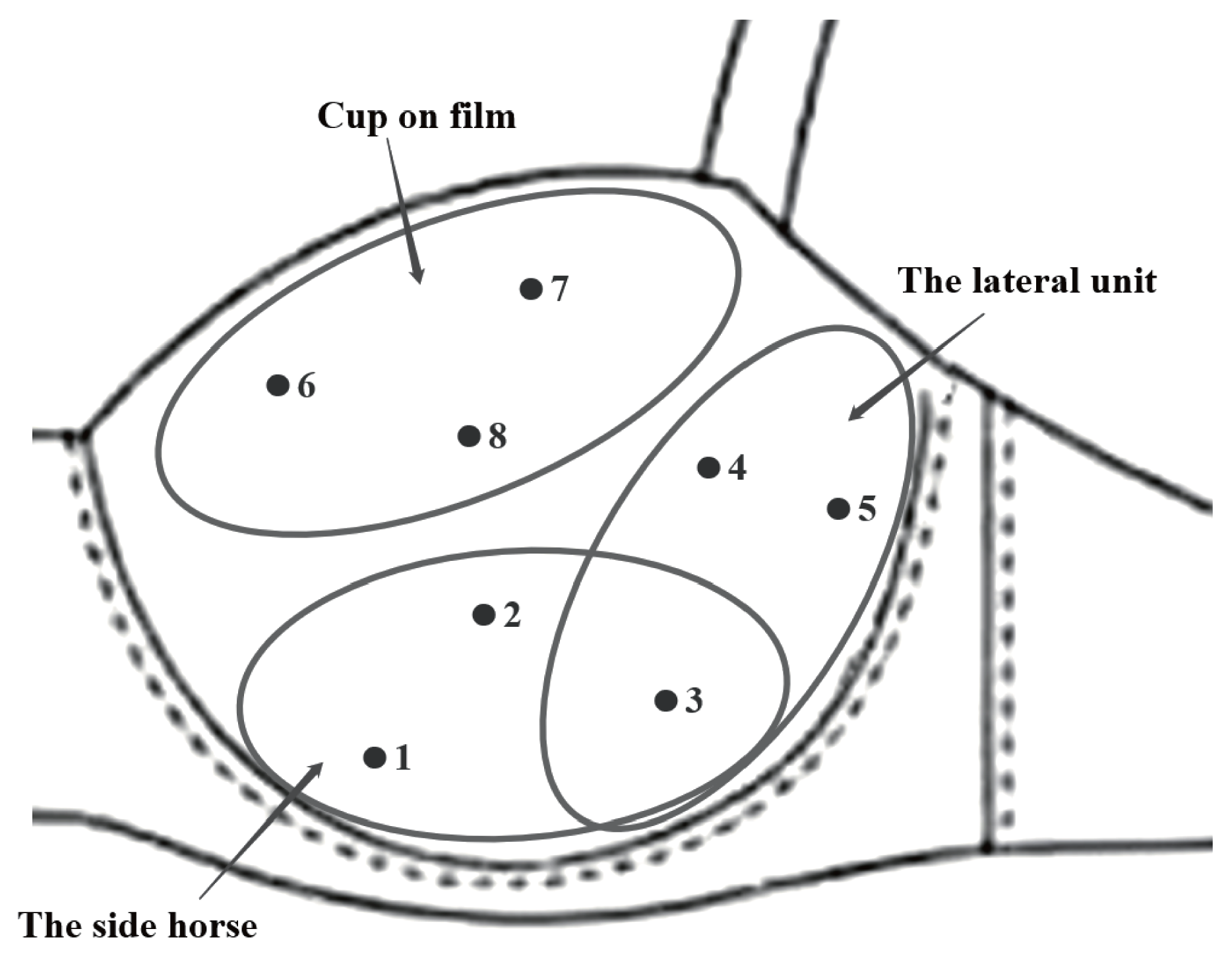
Assuming that the bra mold cup is symmetrical in the experiment, there are three measurement sections, and a total of 8 test points. According to the whole cup, it can be divided into the upper cup and the lower cup. The upper part of the cup has the function of protecting the breast and shaping the appearance. It serves as the measurement section I. The lower part of the cup has the function of supporting and gathering the breast. The position and section of the lateral match position are divided into two measurement sections [15], which are section II and III respectively. In addition, by combining the airbag diameter and mold cup inner surface size, three measurement points are selected for each measurement section, and one measurement point is chosen at the intersection of the lower side and the outer side. The measurement section and the location of the measurement points are shown in Figure 4.
Figure 4.
Measurement point location and measurement section of bra mold cup.
2.4. Experimental Process
Firstly, in order to include the actual pressure when wearing the bra cup in the results of the elastic compression test of the bra cup and make the final result more practical, the wearing pressure experiment of the bra cup was conducted first. According to the experimental results of wearing pressure, the compression displacement interval of each measuring point of the mold cup was set, and then the material elastic distribution of the functional bra mold cup was explored by measuring the pressure and displacement of the mold cup.
The bra cup wearing pressure test was conducted in a quiet environment with a temperature of 25 °C and humidity of 33.2±2%. The subjects were healthy women who had never been pregnant and had never had breast surgery and wore a 75B bra. Mark measuring areas and points for three experimental garments of the same bra mold cup.
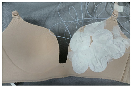
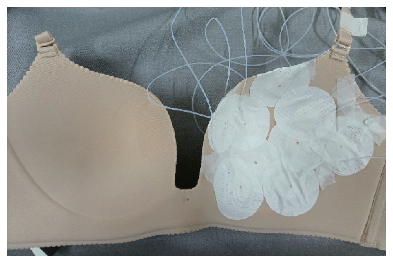
The pressure tester was preheated for 30 min, the airbag was inflated and checked for air leakage. The airbag was pasted and fixed to each measurement point, as shown in Figure 5. The subject wore the experimental clothing bra1, and put the breasts to the appropriate position through the correct try-on method, adjusting the shoulder straps and back buckles to minimize the comparison between the shoulder straps and the back. Force is applied in the vertical direction. Considering the stability of the instrument and human body functions, the subjects limited their breathing and exhaling actions as much as possible. In the experiment, the data was set to be recorded every 1s, and the recording duration was 10 s after clicking “Start”, that is, 10 pressure values were recorded to save the experimental data. The wearing pressure test of the same bra was repeated 3 times. The bra was allowed to stand for 10 min after each test to fully rebound, and then the airbag’s conditions was checked.
Figure 5.
The airbag was pasted and fixed to each measurement point.
According to the pressure values measured at each test point during the wear trial in the pressure experiment, the measured displacement ranges of the mold cup compression experiment were set. The compression displacement ranges of the measuring points 1, 2, 3 and 4 were 1.6-3.2 mm, the compression displacement ranges of the measuring points 5 were 1.0-2.6 mm, and the compression displacement ranges of the measuring points 6, 7 and 8 were 0.2-1.8 mm. Compression displacement range of each point of mold cup are shown in Table 1.
Table 1.
Compression displacement range of each point of mold cup.
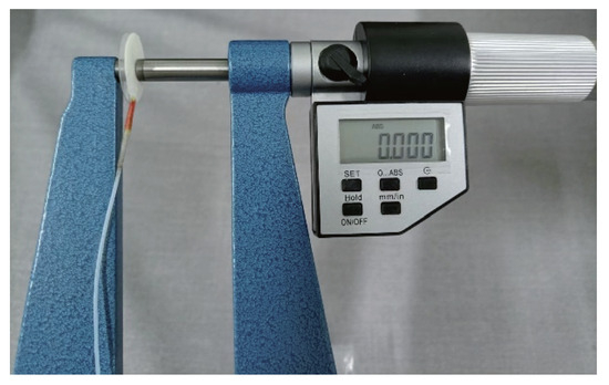
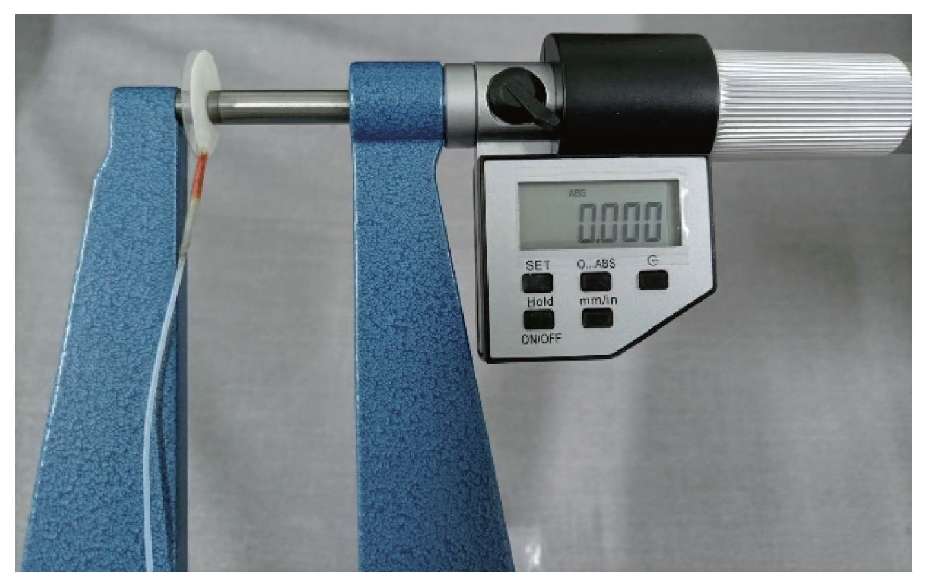
The micrometer is fixed on the test table. In order to make the pressure of the indenter evenly distributed, a plastic round sheet with the same size as the air bag is affixed to the two probe heads of the micrometer. In order to facilitate subsequent operations and avoid displacement of the air bag during compression, the air bag is attached to the stationary side of the micrometer probe. Test points of bra1, bra2 and bra3 bra mold cup were placed at the center of the measuring head of the micrometer while the micrometer was fixed on the test table. The screw handle was turned to adjust the distance between the measuring heads until the pressure value displayed by the pressure tester is between 0 and 0.02 kpa, then the SET key was pressed for zero the adjustment. The operation method is shown in Figure 6. The displacement was incrementing with 0.2 mm spacing, and the pressure value of the displacement was recorded after the pressure value of the pressure tester was stabilized. The pressure values corresponding to the displacement of each point of the three same mold cups were measured to determine the elastic modulus of each measuring point of the mold cups, and the pressure-displacement curves were calculated.
Figure 6.
Zero the micrometer.
3. Result and Discussion
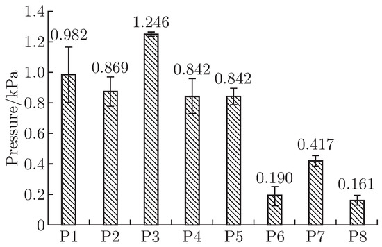
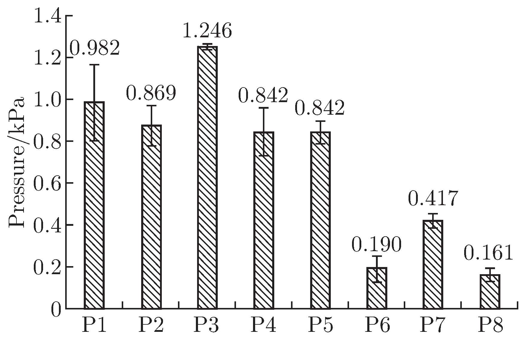
The three mold cup bras of the experimental subjects were measured at different measurement points and measurement sections, and the results show a significant difference. The obtained wearing pressure data were imported for analysis, and the average pressure at each measurement point of the three repeated experiments was drawn as a bar graph. See Figure 7 and Table 2 for the pressure mean and standard error obtained from three experiments at each point. The results show that the pressure on the top of the cup is smaller when the model cup bra is worn, while the pressure at the top of the mold cup increases. The results also demonstrate that the pressure increases with proximity to the lower part. Among them, point 3 and point 1 have the highest wearing pressure, while point 6 and point 8 have the lowest wearing pressure.
Figure 7.
The standard error of the mean of the bra1 bra mold cup wearing pressure test.
Table 2.
Pressure values of each point when wearing bra1 (KPa).
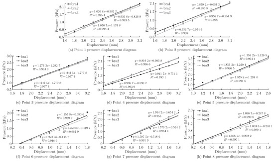
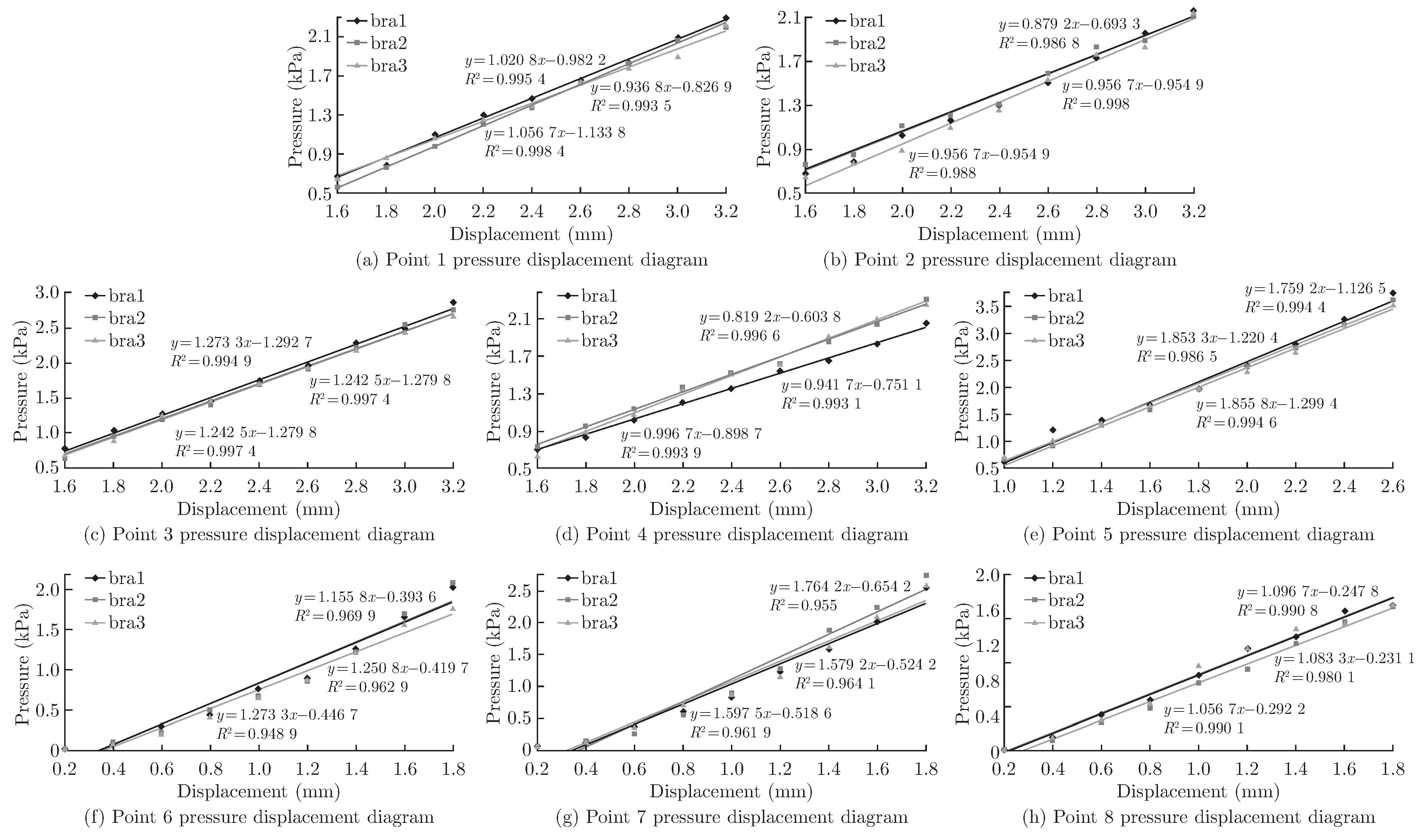
The data obtained from the mold cup compression experiment were imported into the analysis software to draw the pressure-displacement diagrams of the three mold cup bras at each point. The R-squared value of the measured data at each point were calculated to fit the linear equation, where the R-squared value is equal to greater than 0.95. There is a strong linear correlation between the compression displacement and the pressure at each measurement points. Figure 8 and Table 3 and Table 4 show the pressure-displacement diagrams of each test point for the three same functional mold cup bras.
Figure 8.
Pressure-displacement diagram of each measuring point of the three bra mold cups.
Table 3.
Pressure-displacement equations at each measurement point of the three bra mold cups.
Table 4.
Sponge elastic coefficient range of each measuring area of mold cup.
The elastic coefficient of the sponge at the top of the cup is in the range of 1.1-1.8, and the relationship between the elastic coefficients of the three measurement points is point 7>point 6>point 8. The range of the sponge elastic coefficient at the lower side is 0.9-1.3. The size relationship of the elastic coefficient of the measurement points is point 3>point 2>point 1. The range of the sponge elastic coefficient at the outer edge is 0.8-1.9, and the size relationship of the elastic coefficients of the three measurement points is point 5>point 3>point 4. The relationship between the elastic coefficient of each measurement section of the mold cup is the upper part of the cup > Lateral unit > The side horse. The lateral unit and the side horse is not much different, and is much smaller than the upper cup.
Therefore, for the upper part of the mold cup, the closer to the upper edge of the mold cup and the lower part of the bra, the greater the elasticity coefficient of the sponge, the worse the elasticity of the sponge, and the firmer the hand. For the lower part of the mold cup, the closer to the center of the mold cup, the smaller the elastic coefficient of the sponge, the better the elasticity and the softer the hand feel. In the central section of the mold cup, the measurement point at the position of the mold cup has the smallest elastic coefficient and the sponge had better elasticity.
4. Conclusion
By measuring the pressure value of the functional bra mold cup during wearing and the pressure displacement value of each measuring point of the mold cup, the pressure and elasticity distribution of each section of the bra mold cup were examined. The main conclusions are as follows:
1) The average pressure and maximum pressure of each measurement point are different when the functional bra mold cup is worn, and the wearing pressure of each section is also significantly different. The order of pressure in each measurement section is: lower side position > outer side position > cup upper piece. The measurement point near the lower position of the mold cup is subjected to the greatest pressure, followed by the larger pressure at the outer position. Therefore when the bra mold cup is worn, the breast is supported and gathered. In the design and production of bra cup, attention should be paid to reduce the wearing pressure here to improve the wearing comfort.
2) The sponge elasticity of each section of this mold cup bra has an obvious difference. The sponge elasticity coefficient of each measurement section is in the order of: the lower piece position < outer piece < cup plate. For the mold cup as a whole, the lower piece of the mold cup sponge has a smaller elastic coefficient than the upper piece of the mold cup, and it feels softer. Combined with the data results of the mold cup wearing pressure experiment, the sponge elasticity coefficient corresponding to the section with large wearing pressure is small, which is conducive to the bra mold cup supporting and gathering the breast to achieve the effect of breast shaping, while improving the pressure comfort of the mold cup wearing.
3) The upper part of the bra mold can protect the breast and improve the appearance. The pressure generated by the human body when wearing is less. In order to make the wearing curve wider and more frivolous, the sponge in this section is thin and hard, and the sponge elasticity coefficient should be designed larger. The lower part of the cup can support and hold the breast together, which is an important functional section of the bra mold cup. The lateral unit mainly has the function of gathering the breast, and the side horse has the primary function of supporting the breast, so as to achieve the effect of breast shaping. Generally, the pressure on the lower part of the cup is high when worn. In order to reduce the discomfort caused by the pressure, the sponge in this section is thick and soft, and the sponge elasticity coefficient should be small, so as to realize the shape of the chest for comfortable wear.
4) In this paper, functional areas are divided according to the shaping mechanism of the bra mold cup, and Hooke’s law and physical experiment are combined to obtain the wearing pressure and elastic distribution law of each functional area of the mold cup. The measurement method is also suitable for measuring and analyzing the pressure and elastic distribution of other types of bra cup. The analysis results can be used to set the elastic parameters of the mold cup material in the finite element simulation experiment, reduce the simulation experiment error, and provide the technical basis for the design and production of the bra mold cups.
Acknowledgments
This research work is supported by the Key Laboratory of Silk Culture Heritage and Products Design Digital Technology, Ministry of Culture and Tourism, P. R. China (Project No. 2020WLB03), the opened research program granted by Wuhan Textile and Clothing Digital Engineering Technology Research Center in 2022 (SZH202202), Natural Science Basic Research Program of Shaanxi (Program No. 2023-YBSF-203), Young Innovation Team Research Plan Project of the Shaanxi Provincial Education Department in 2022 (22JP027) and the Shaanxi Union Research Center of University and Enterprise for Apparel Intelligent Design and Manufacture. Simulation Research (Project No. 11310031252003) and the Shaanxi Apparel Intelligent Design and Manufacturing Engineering Technology Research Center.
References
- Wu, L.; Yick, K.; Ng, S.; et al. Parametric design and process parameter optimization for bra cup molding via response surface methodology. Expert Syst. Appl. 2012, 39(1), 162171. [Google Scholar] [CrossRef] [Scilit]
- Wu, H.Y.; Zhang, X.; Ying, B.A.; et al. Analysis of Molding Process Parameters of Bra Cup. J. Fiber Bioeng. Inform. 2009, 1(4), 275–280. [Google Scholar] [CrossRef] [Scilit]
- Wu, J.; Wang, T. The application of UG in the design of bra mold cups. Int. Text. Her. 2010, 38(9), 67-68; 70-72, 74. [Google Scholar]
- Ma, J.J.; Ying, B.A.; Wu, L.; et al. Parametric Modeling Method for Inner Surface of Functional Bra Mold Cup in Personalized Customization. J. Fiber Bioeng. Inform. 2022, 15(2), 105–116. [Google Scholar] [CrossRef] [Scilit]
- Wang, Y.P.; Ping, Zhao; Gao, X.S.; et al. Objective evaluation of pressure comfort of female corsets. J. Text. Res. 2006, 27(11), 90–93. [Google Scholar]
- Liu; Chi; Miao; et al. Enhancing pressure comfort of a bra’s under-band. Text. Res. J. 2018, 88(19), 2250–2257. [Google Scholar] [CrossRef] [Scilit]
- Li, Y.; Zhang, X.; Yeung, K. W. A 3D Biomechanical Model for Numerical Simulation of Dynamic Mechanical Interactions of Bra and Breast during Wear. Fiber 2003, 59(1), 46–55. [Google Scholar] [CrossRef] [Scilit]
- Wang, L. Sports Bra Design Based on Dynamic Elder Women Avatar. J. Fiber Bioeng. Inform. 2021, 14(1), 1–12. [Google Scholar] [CrossRef] [Scilit]
- Zhu, C.L.; Long, W.; Ying, B.A.; et al. Finite Element Simulation of the Dynamic Pressure Distribution of a Typical Compression Sports Bra During Wearing. J. Fiber Bioeng. Inform. 2020, 13(4), 211–219. [Google Scholar] [CrossRef] [Scilit]
- Sun, Y.; Yick, K.; Cai, Y.; et al. Finite Element Analysis on Contact Pressure and 3D Breast Deformation for Application in Women’s Bras. Fibers Polym. 2021, 22(10), 2910–2921. [Google Scholar] [CrossRef] [Scilit]
- Xu, Y.Y. Research on the fit of bra mold and cup based on finite element analysis; Zhejiang Sci-Tech University, 2016. [Google Scholar]
- Long, W.; Kit-Lun, Y.; Sun-Pu, N.; et al. Modeling of Flexible Polyurethane Foam Shrinkage for Bra Cup Molding Process Control. Polymers 2018, 10(5), 472. [Google Scholar] [CrossRef] [Scilit] [PubMed]
- Duan, X.Y. Design and comfort evaluation of the main shaping function bra; Dong Hua University, 2012. [Google Scholar]
- Peng, H. Study on the influencing factors of shaping effect and pressure comfort of non-wire mold cup bra; Soochow University, 2017. [Google Scholar]
- Cui, X. Research on the relationship model in the design of the bra mold cup; Xi’an Engineering University, 2013. [Google Scholar]

© 2022 Textile Bioengineering and Informatics Society. This article is an open access article distributed under the terms and conditions of the Creative Commons Attribution (CC BY) license (https://creativecommons.org/licenses/by/4.0/).