


Abstract
Lotus root-like fibers and hollow structure fibers have been extensively studied in many different fields due to a large specific surface area and high porosity. However, most of the prepared materials have only one lotus root-like or hollow structure. Here, in this paper, the coaxial electrospinning poly(lactic acid) (PLA) nanofibers had hollow and lotus root-like structures. The porosity of the cross section was quantitatively analysed by MATLAB, and the oil sorption experiment was also carried out. In the hollow structure, when the flow rate ratio of the core/shell solution was 1:2 or 1:4, the pore porosity was about 41%, larger than 34.88% (1:3), while the pore porosity at 19-22 kV was stable at about 41% ± 2%. On the contrary, the lower the porosity, the better the spinning state and the higher the hollow ratio. In the lotus root-like fibers, the porosity values were about 23% ± 2% under different spinning conditions, which means that the lotus root-like porosity was not significantly affected by the flow rate ratio of core/shell solution and voltage. Meanwhile, the absorption capacity of the lotus root-like fibers to diesel oil is more than 1.5 times that of hollow fibers.
1. Introduction
Poly(lactic acid) (PLA) is considered to be one of the most promising renewable, green and environmental friendly material. Starch, which is the raw material, can be extracted from some plants such as corn, wheat, and cassava. Enzymes break down to produce glucose, and the lactic acid bacteria are fermented to become lactic acid. When lactic acid is added with catalyst at high temperature and low pressure, poly(lactic acid) (PLA) can be directly synthesized by condensation polymerizations [1,2,3,4,5,6,7,8].
Nowadays, the oil spill on the sea surface is one after another, which has a serious impact on ecological environment. Due to its advantages of high efficiency and no secondary pollution, nanofiber membranes have unique advantages in oil/water adsorption [8,9,10,11,12], and gradually become the subject of study.
In the present study, poly(lactic acid) (PLA) nanofibers with hollow [13,14] and lotus-root-like [15,16,17] structures were prepared using the coaxial electrospinning method [18,19]. To achieve this goal, the prepared PLA/PVA nanofibers with a core/shell structure were immersed in deionized water for 48 h to remove the core (PVA). The cross-sectional porosities of the prepared nanofibers were analysed quantitatively using MATLAB, and the oil sorption experiments were also performed. The results of the porosity analyses show that, for the hollow structure, when the flow rate ratio of the core/shell solution was 1:2 or 1:4, the cross-sectional porosity was about 41%, larger than 34.88% (flow rate ratio=1:3). However, the cross-section porosity seemed to be voltage-independent, which was demonstrated by the fact that the porosity was stable at 41% ± 2% when the voltage varied in the range of 19-22 kV. While in the lotus-root-like fibers, the porosity value was not affected by these parameters. The results of the oil sorption experiments demonstrated that the absorption capacity of the lotus-root-like structure fibers to diesel oil is more than 1.5 times that of the hollow structrue fibers.
2. Materials and Experiments
2.1. Materials
PLA (Mw=1.0 × 10⁵ g/mol) was purchased from Zhejiang Hai Zheng Biological Materials Co., Ltd., Zhejiang, China. PVA (Mw=9.5 × 10⁴ g/mol, percent hydrolyzation 95%) was purchased from J&K scientific Co., Ltd., Beijing, China. N, N- Dimethylacetamide (DMAC), Dichloromethane (DCM) and Dimethyl sulfoxide (DMSO) were purchased from National Medicine Group Chemical Reagents Co., Ltd., Beijing, China. Diesel oil was obtained from Suzhou Difite Filtration Technology Co., Ltd., Suzhou, China. All chemicals were of analytical grade and used without further purification.
2.2. Preparation of PLA Nanofibers with Hollow and Lotus-root-like Structures
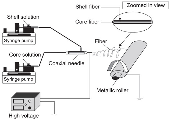
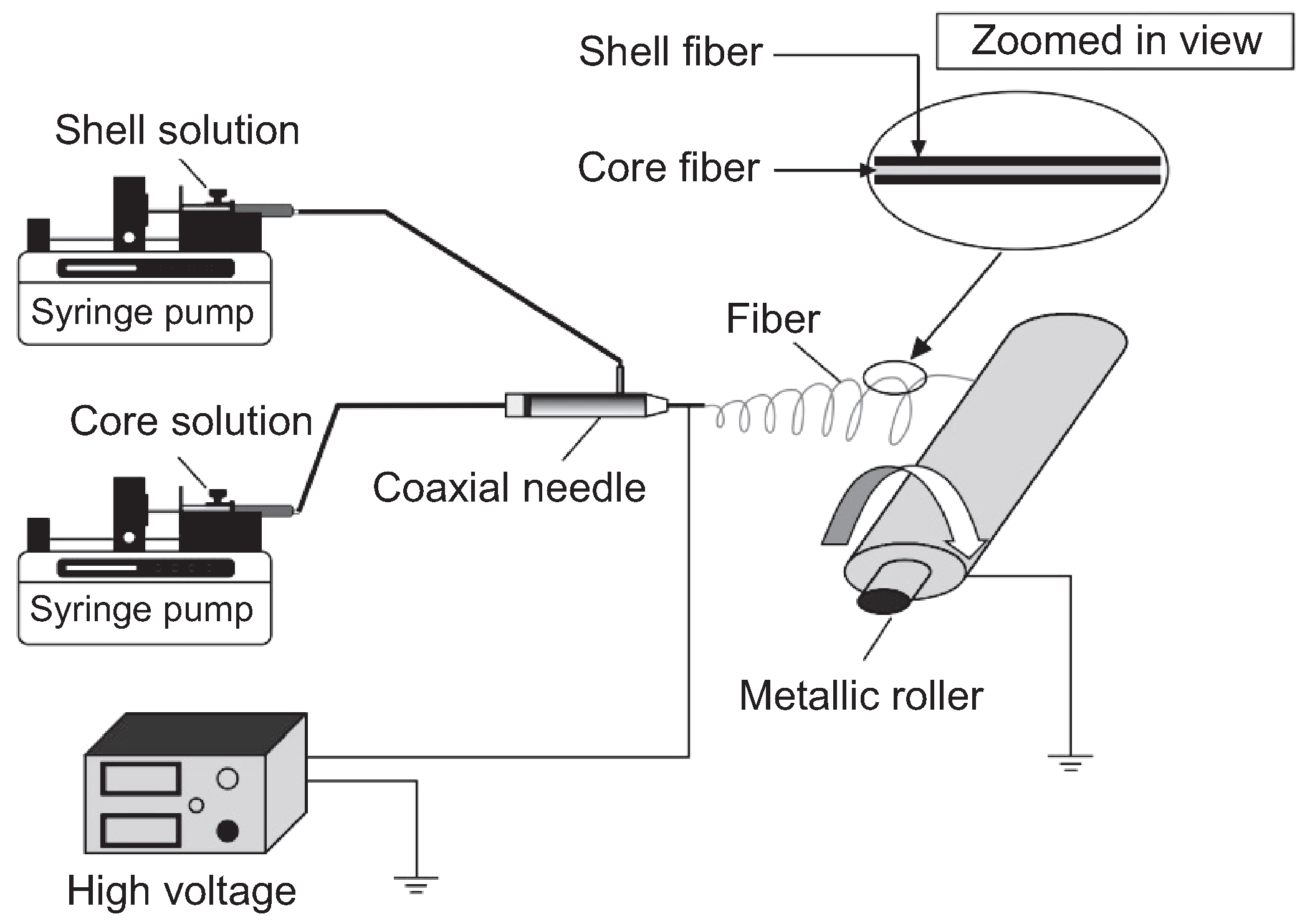
8 wt.% PLA was dissolved in a DCM/DMAC (mass ratio of 10:1, w/w) mixed solvent, 2 wt.% PVA was dissolved in DMSO, and DCM was added to the PVA/DMSO solution (where the DMSO/DCM ratio was 2:1, w/w) after PVA was completed dissolved. Then both of them stirred at room temperature for about 12 h. Two 5 mL syringes were used—one to absorb the shell solution (PLA) and the other to absorb the core solution (PVA or PLA), and then fixed onto two syringe pumps (KDS-100, KD Scientific, Inc., Holliston, MA, USA). The general setup of the apparatus is shown in Figure 1. Tubes were used to connect the syringes and the coaxial needle, and a high-voltage power supply (DWP503-1ACDF, Tianjin Dongwen High Voltage Co., Tianjin, China) was connected to the coaxial needle through a wire.
Figure 1.
Schematic of coaxial electrospinning apparatus.
The electrospun PLA/PVA or PLA/PLA composite nanofiber membrane was deposited onto the metallic roller, which was positioned 12 cm from the needle tip. Meanwhile the relative humidity (RH) of the environment was 45% ± 3%. PLA nanofibers with hollow and lotus-rootlike structures were prepared by adjusting the flow rate ratio of core/shell solution (0.3 mL/h: 0.6 mL/h (1:2), 0.3 mL/h: 0.9 mL/h (1:3) and 0.3 mL/h: 1.2 mL/h (1:4)) and spinning voltage (19 kV, 20 kV, 21 kV, 22 kV and 23 kV). The control sample which only has lotus-root-like structure was prepared at the flow rate ratio of 0.3 ml/h: 0.9 ml/h (core/shell solution = PLA/PLA) and the voltage was 23 kV. The distance and the RH of the environment were the same as before (12 cm and RH of 45% ± 3%).
In order to obtain PLA nanofibers with hollow and lotus-root-like structures, it was necessary to remove the core (i.e. PVA) fibers in the PLA/PVA composite nanofibers. To this end, the shell/core PLA/PVA nanofiber membrane was soaked in deionized water; this deionized water was required to be replaced about every 2 h for a total duration of 48 h. Finally, hollow PLA fibers were obtained after drying in a vacuum drying oven at 35 °C for 12 h.
2.3. Preparation of Cross-section
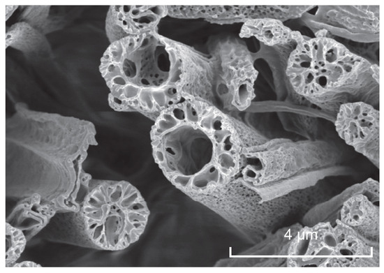
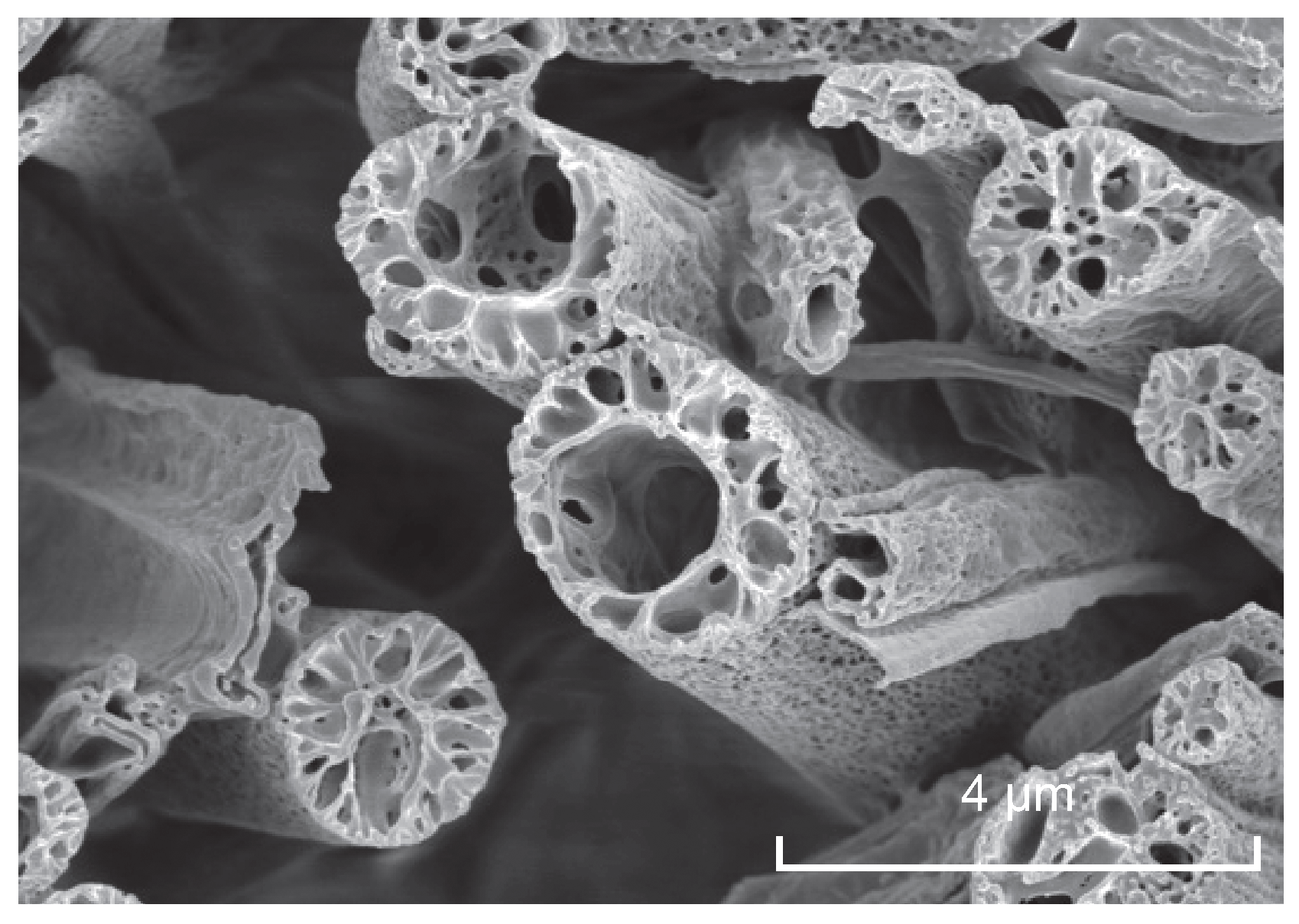
The nanofiber membrane was cut into a rectangle (30 mm×5 mm), which was fixed on two slides that were separated by a distance of 5 mm. The fiber cross-section, as shown in Figure 2, can be achieved after the nanofiber membrane in liquid nitrogen for about 1 minute. The cross-section of the hollow PLA nanofiber membrane was observed using FE-SEM (S-4800, Hitachi Ltd. Tokey, Japan).
Figure 2.
FE-SEM image of PLA nanofibers’ cross-section.
2.4. Cross-sectional Porosity
The cross-sectional porosity of the porous PLA nanofibers, which included the hollow and lotusroot-like structures, was calculated.
First, Photoshop was used to cut out a rectangular section (depicting either the hollow or lotusroot-like structure) of the FE-SEM image, which was then input into the programmed MATLAB to obtain the desired results: a binarized image of the total cross-sectional area, a binarized graph of a lotus-root-like or a hollow structure, and a data sheet of the ratio of every single pore area to total cross-sectional area (the largest ratio corresponds to the hollow porosity, and when the single pore area ratio is less than 0.2%, it well be eliminated). The total cross-sectional porosity (Sp) is equal to the sum of each small porosity (S1,S2,··· ,Sn), and the ratio of the hollow porosity to the pore porosity is denoted as R. That is,
Sp = S1 + S2 + ··· + Sn
R = Hollow porosity/Pore porosity
Under the same electrospinning conditions, porosity of hollow and lotus-root-like fibers measured 10 FE-SEM images, the maximum and minimum measured values were discarded, and the rest were averaged.
2.5. Oil Sorption Test
The control sample (with lotus-root-like structure) and the PLA nanofiber membranes prepared at 19 kV (with hollow and lotus-root-like structures) were subjected to an oil sorption test. 50 g of diesel oil was poured into a 100 mL beaker. The dried nanofiber membranes were immersed in the diesel oil. After 30 minutes, the fiber membrane was taken out from the beaker and dripped by its own gravity for 1 minute. The diesel oil sorption capacity was measured 6 times to calculate the average value.
The oil sorption capacity was calculated as follows:
where, Q is the oil sorption capacity (g/g), M0 is the original mass of the fiber membrane and M1 is the mass after oil sorption for 30 mins.
Q = (M1 − M0)/M0
3. Results and Discussion
3.1. Hollow Structure
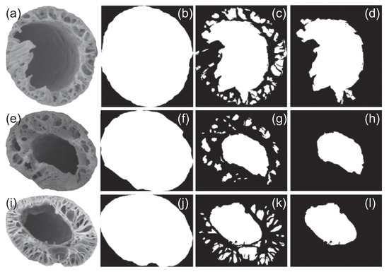
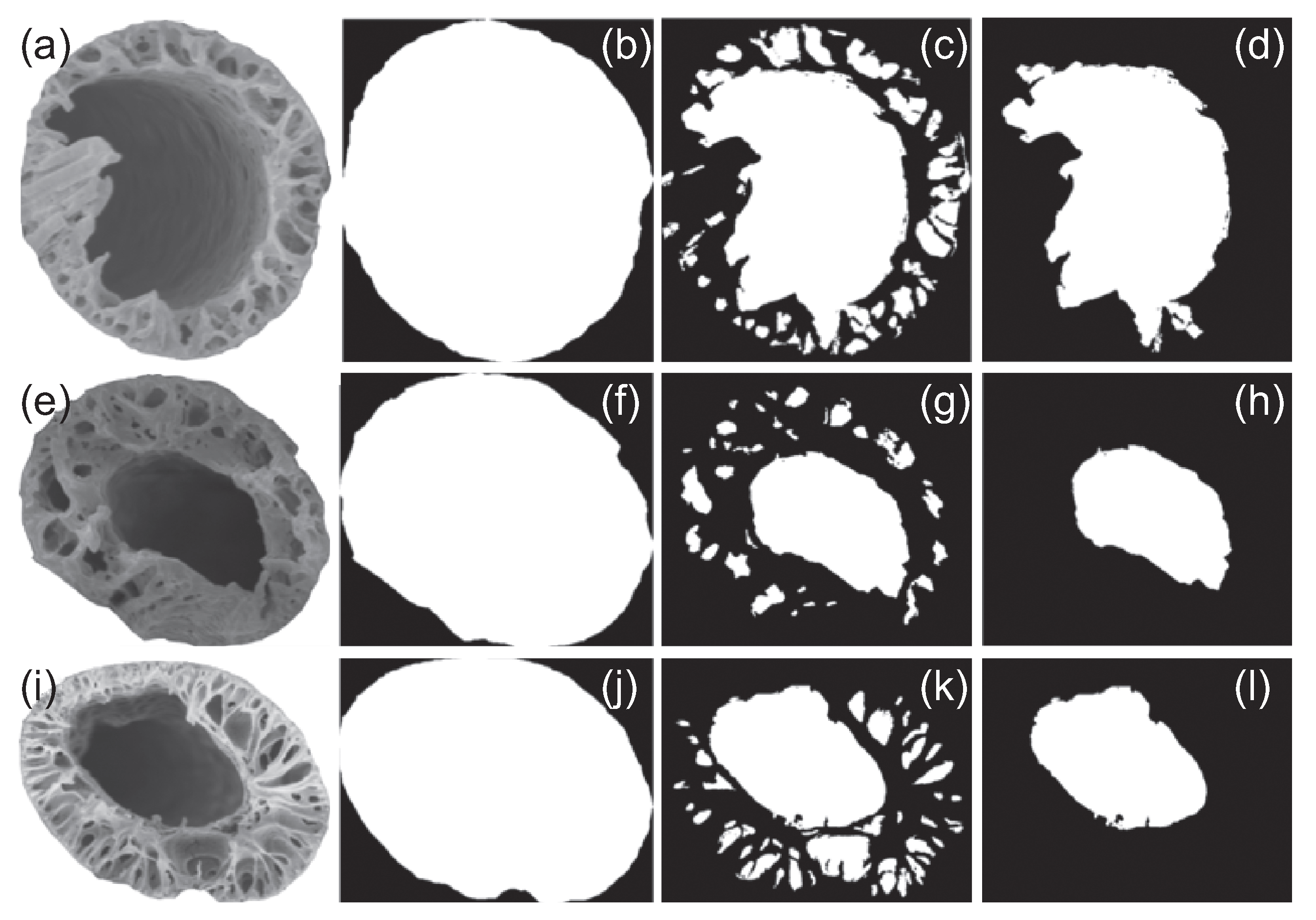
From Figure 3, the FE-SEM images, the binarization of the total cross-sectional area, the binarization of porous structure, and the binarization of hollow structure at different feed rate ratio of core/shell solution can be visually watched. It can be clearly observed that both the fiber cross section and the hollow pores are irregular and tend to be elliptical in shape, and that there is a circle of elliptical holes on the elliptical ring with a certain thickness at the same time. The spacing between coaxial needle can ensure that the shell and core spinning liquid do not dissolve in the needle channel. The shell and core layers spinning liquid jointly formed a jet, and shell/core nanofibers (PLA/PVA) were ejected from Taylor cone. Removing the core (i.e. PVA) fibers in the PLA/PVA composite nanofibers can get hollow structure.
Figure 3.
Original (FE-SEM) and binarization of the cross-section with different feed rate ratio of core/shell solution, (a, b, c, d): 1:2; (e, f, g, h): 1:3; and (i, j, k, l): 1:4. (a, e, i): FE-SEM images; (b, f, j): binarized images of total area of cross-section; (c, g, k): binarized images of porous structure; and (d, h, l): binarized images of hollow structure.
As can be seen from Table 1, when the flow rate ratio of core/shell solution was 1:2 or 1:4, the pore porosity was about 41%, larger than 34.88% (1:3). Analyzing its reason may be spinning state at 1:3 was the most stable, the number of hollow fiber roots was also more, and hollow fibers were uniform, unlike the other two parameters which spun several extremely large hollow fibers.
Table 1.
Cross-sectional porosity of hollow fibers fabricated with different feed rate ratio of core/shell solution.
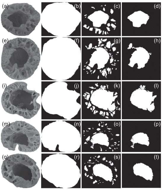
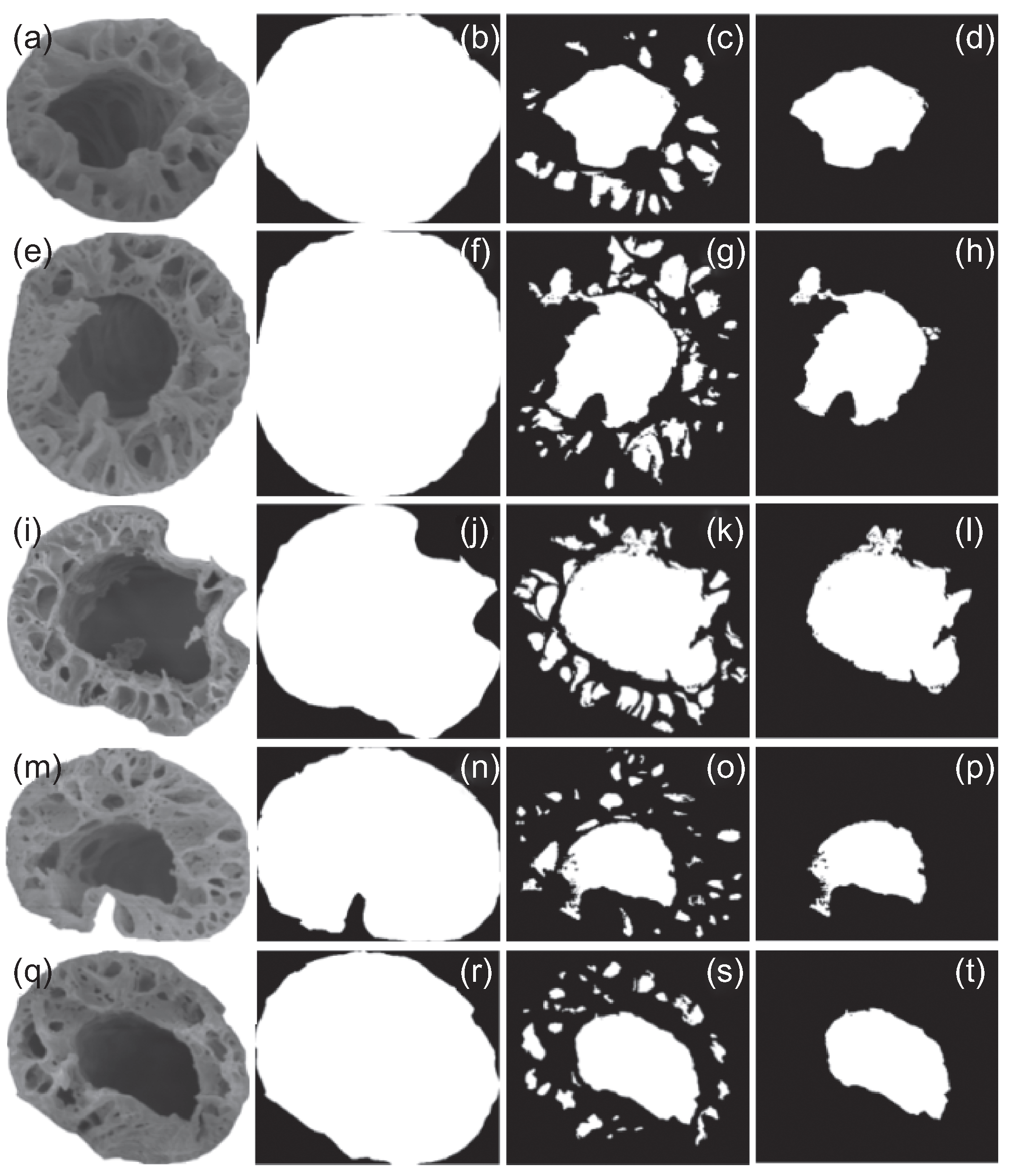
Figure 4 shows the case of electrospinning at different high voltages. In Table 2, the pore porosity at 23 kV was the lowest, being 34.88% ± 6.41%, and the pore porosity at other voltages was about 41% ± 2%. The reason was that the voltage at 23 kV was too high to electrospinning.
Figure 4.
Original (FE-SEM) and binarization of the cross-section with different high voltages, (a, b, c, d): 19 kV; (e, f, g, h): 20 kV; (i, j, k, l): 21 kV; (m, n, o, p): 22 kV; and (q, r, s, t): 23 kV. (a, e, i, m, q): FE-SEM images; (b, f, j, n, r): binarized images of the total area of the cross-section; (c, g, k, o, s): binarized images of porous structure; (d, h, l, p, t): binarized images of hollow structure.
Table 2.
Cross-sectional porosity of hollow fibers fabricated with different high voltages.
According to Table 1 and Table 2, when the spinning state was stable, the number of hollow fiber roots was large and the size was even, its R value was about 75% ± 5% and the little pore number was about 12 ± 2. It can be seen that the hollow structure of PLA nanofiber prepared in this experiment has general characteristics.
3.2. Lotus-Root-like Structure
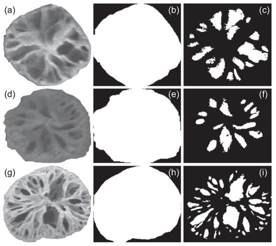
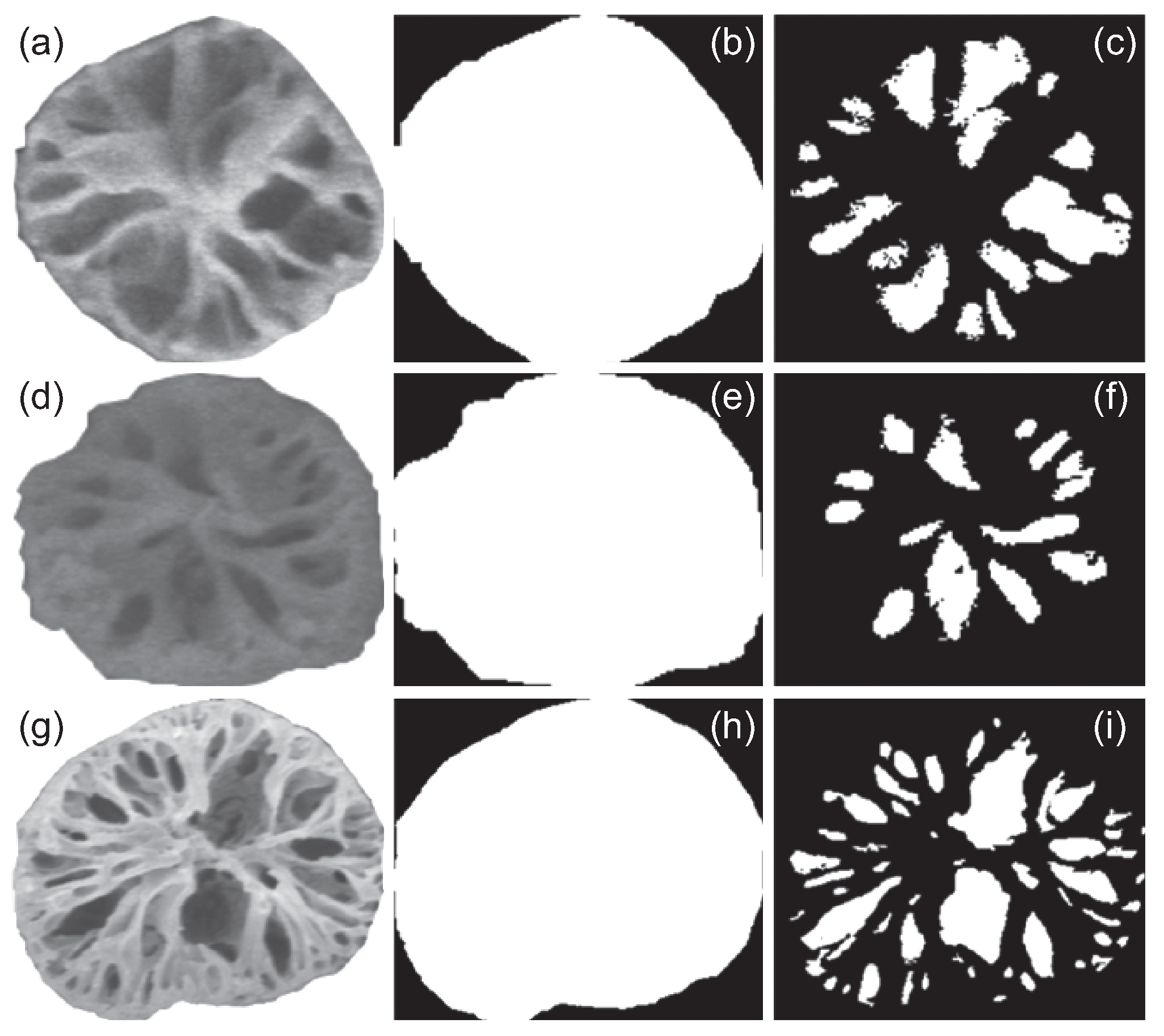
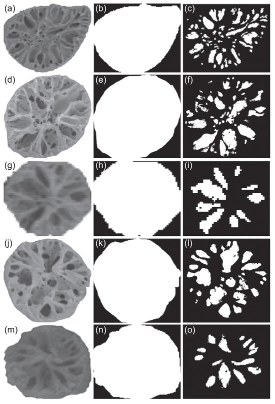
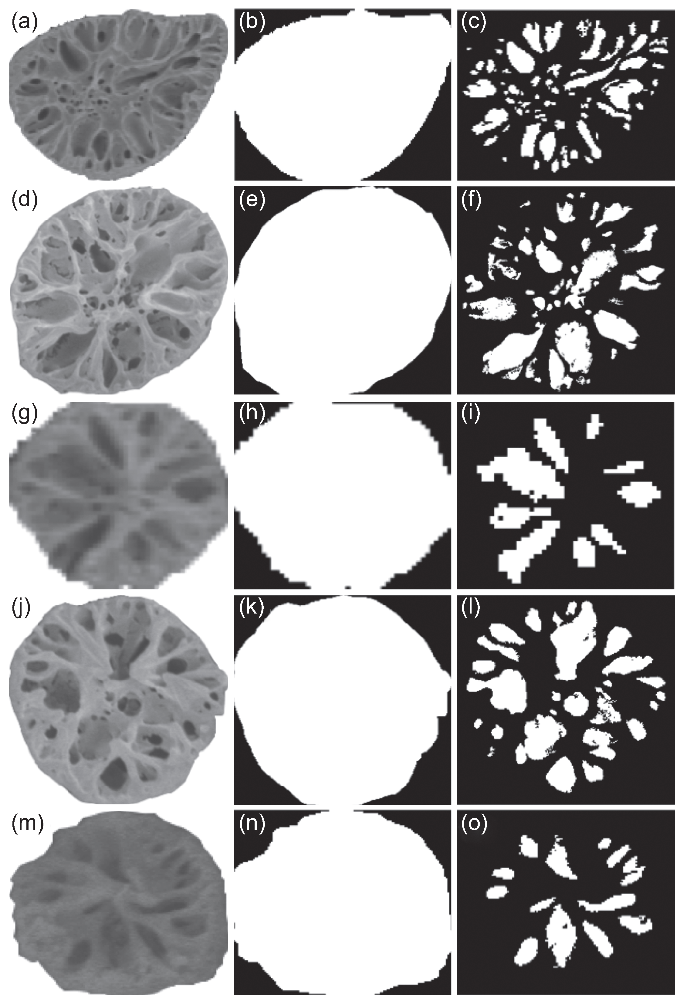
As shown in Figure 5 and Figure 6, the PLA nanofiber with hollow structure prepared in this paper also has a lotus-root-like structure, because the proportion of hollow fiber in this research less than 100%, and the non-hollow fiber was neat PLA nanofiber. Relevant studies shown, it can obtain porous nanofibers with either internal porosity or surface roughness by electrospinning a kind of hydrophobic polymer from a volatile and water-compatible solvent at a proper level of relative humidity [19]. The pores inside the fibers were formed by the volatilisation of the spinning solution and also by thermally induced phase separation.
Figure 5.
Original (FE-SEM) and binarization of the cross-section with different feed rate ratio of core/shell solution, (a, b, c): 1:2; (d, e, f): 1:3; and (g, h, i): 1:4. (a, d, g): FE-SEM images; (b, e, h): binarized images of the total area of the cross-section; (c, f, i): binarized images of porous structure.
Figure 6.
Original (FE-SEM) and binarization of the cross-section with different high voltages, (a, b, c): 19 kV; (d, e, f): 20 kV; (g, h, i): 21 kV; (j, k, l): 22 kV; and (m, n, o): 23 kV. (a, d, g, j, m): FE-SEM images; (b, e, h, k, n): binarized images of the total area of the cross-section; (c, f, i, l, o): binarized images of porous structure.
It can be found from Table 3 and Table 4 that the porosity values of the lotus-root-like fibers prepared under different parameters did not change much, about 23% ± 2%. This indicates that the cross-section porosity of neat PLA nanofiber was not much affected by the flow rate ratio of core/shell solution and voltage in the electrospinning process parameters
Table 3.
Cross-sectional porosity of lotus-root-like fibers fabricated with different feed rate ratio of core/shell solution.
Table 4.
Cross-sectional porosity of lotus-root-like fibers fabricated with different high voltages.
3.3. Oil Sorption Capacity
As shown in Table 5, the oil sorption capacity of the control sample (with lotus root-like structure) is 23.52 ± 2.41 g/g, and that of the PLA nanofiber membrane (with lotus root-like and hollow structures) at 19 kV is 13.94 ± 3.44 g/g. The oil sorption capacity of the control sample is more than 1.5 times that of the hollow membranes, and there may be two reasons.
Table 5.
Oil sorption capacity of lotus-root-like structure and hollow structure.
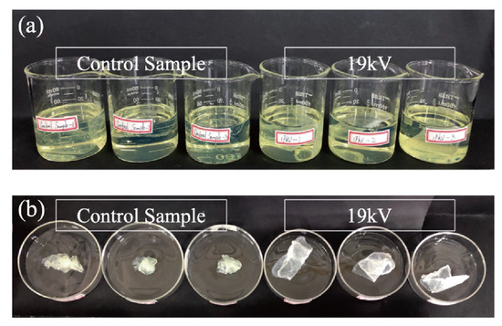
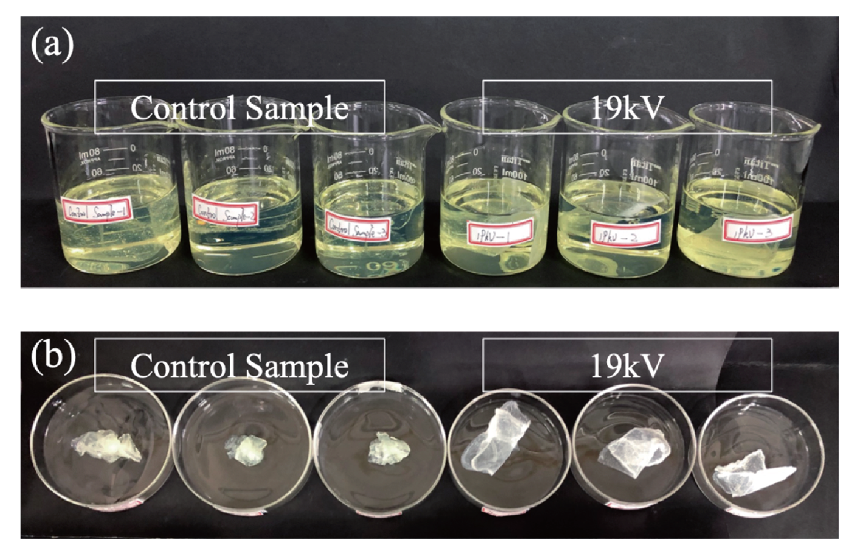
First of all, from the macro level, the control sample fluffy and surface viscosity are much larger than the hollow nanofiber membranes. In order to obtain hollow nanofibers, the core/shell PLA nanofiber membranes need to be immersed in deionized water for 48 hours. In this process, PLA hydrolyzed slowly in deionized water, and the water-soluble PVA dissolved in deionized water was likely to re-form a film on the surface of PLA, so that the fluffy and surface viscosity are greatly reduced. This can also be seen intuitively from Figure 7b.
Figure 7.
Oil sorption diagram.
Secondly, from the microstructure, the ability of hollow fibers to adsorb oil is smaller than that of lotus root-like fibers, because the internal pore size of PLA nanofibers has a certain influence on the oil sorption capacity. The hollow fiber membrane has good connectivity, and the oil from one channel to enter, but will be very easy to ran out from another channel, so it can’t trap diesel efficiently.
4. Conclusion
In this paper, cross-sectional porosity of PLA nanofibers with hollow and lotus-root-like structures had been characterized scientifically and quantitatively.
When the flow rate ratio was 1:3, the high voltage was 23 KV, and the receiving distance was 12 cm, the porous porosity was the smallest, which was 34.88% ± 6.41%. However, the spinning state under this parameter was the most stable. When the flow rate ratio was 1:3, the receiving distance was 12 cm, and the high voltages were adjusted from 19 kV to 22 kV, the porous porosity was about 41% ± 2%. From the R value and the number of small pores, we can find that the hollow structure of PLA nanofiber prepared in this work has general characteristics.
In the lotus-root-like fiber, the porosity values were around 23% ± 2% at different electrospinning conditions, which means that the lotus-root-like porosity was not significantly affected by flow rate ratio of core/shell solution and voltage. All the pores prepared in this study are close to the ellipse, whether they are hollow pore and small pores in the hollow or the lotus-root-like fibers. Lotus-root-like fibers have 1.5 times the absorption capacity of diesel oil than hollow fibers. Although two possible reasons were highlighted, this phenomenon remains to be studied more deeply in the future.
References
- Jiang, A.; Pan, Z. Cross-section Porosity of Porosity of Porous PLA Nanofibers with Hollow-structure [C]. Textile Bioengineering and Informatics Symposium Proceedings, 2019; pp. 132–138. [Google Scholar]
- Sangeetha, V. H.; Deka, H.; Varghese, T. O.; et al. State of the art and future prospectives of poly(lactic acid) based blends and composites [J]. Polym. Compos. 2018, 39(1), n/a–n/a. [Google Scholar] [CrossRef] [Scilit]
- Tachaphiboonsap, S.; Jarukumjorn, K. Toughness and Compatibility Improvement of Thermoplastic Starch/Poly(lactic Acid) Blends [J]. Adv. Mater. Res. 2013, 747, 67–71. [Google Scholar] [CrossRef] [Scilit]
- Pozo Morales, A.; Güemes, A.; Fernandezlopez, A.; et al. Bamboo–Polylactic Acid (PLA) Composite Material for Structural Applications: [J]. Materials 2017, 10(11), 1286. [Google Scholar] [CrossRef] [Scilit] [PubMed]
- Li, Y.; Lim, C.T.; Kotaki, M. Study on structural and mechanical properties of porous PLA nanofibers electrospun by channel-based electrospinning system [J]. Polymer 2015, 56, 572–580. [Google Scholar] [CrossRef] [Scilit]
- Wang, Z.; Zhao, C.; Pan, Z. Porous bead-on-string poly(lactic acid) fibrous membranes for air filtration [J]. J. Colloid Interface Sci. 2015, 441, 121–129. [Google Scholar] [CrossRef] [Scilit] [PubMed]
- Wang, Z.; Pan, Z. Preparation of hierarchical structured nano-sized/porous poly(lactic acid) composite fibrous membranes for air filtration [J]. Appl. Surf. Sci. 2015, 356, 1168–1179. [Google Scholar] [CrossRef] [Scilit]
- Gu, Y.Q.; Wang, Z.; Sun, Y.; et al. Micro-scale PLA Fibrous Membranes for Adsorption of Cigarette Smoke [J]. Fibers Polym. 2018, 19(3), 515–523. [Google Scholar] [CrossRef] [Scilit]
- Liu, H.; Cao, C. Y.; Wei, F. F.; et al. Flexible macroporous carbon nanofiber film with high oil adsorption capacity [J]. J. Mater. Chem. A 2014, 2(10), 3557. [Google Scholar] [CrossRef] [Scilit]
- Huang, C.; Thomas, N. L. Fabricating Porous Poly(lactic acid) Fibers via Electrospinning [J]. Eur. Polym. J. 2017, S0014305717316294. [Google Scholar]
- Sreekala, M. S.; KoichiGoda; Devi, P. V. Sorption characteristics of water, oil and diesel in cellulose nanofiber reinforced corn starch resin/ramie fabric composites [J]. Compos. Interfaces 2008, 15(2-3), 281–299. [Google Scholar] [CrossRef] [Scilit]
- Bandegi, A.; Moghbeli, M. R. Effect of solvent quality and humidity on the porous formation and oil absorbency of SAN electrospun nanofibers [J]. J. Appl. Polym. Sci. 2017, 135(1), 45586. [Google Scholar] [CrossRef] [Scilit]
- Nat’alia, M.T.; Madrona, G.S.; Ferreira, F.B.; et al. High Performance of Asymmetric Alumina Hollow Fiber Membranes for the Clarification of Genipap (Genipa americana, L.) Fruit Extract [J]. In Food and Bioprocess Technology; 2018; pp. 1–12. [Google Scholar]
- Wang, P.; Chung, T.S. Exploring the spinning and operations of multibore hollow fiber membranes for vacuum membrane distillation [J]. Aiche J. 2014, 60(3), 1078–1090. [Google Scholar] [CrossRef] [Scilit]
- Wang, P.; Chung, T.S. Design and fabrication of lotus-root-like multi-bore hollow fiber membrane for direct contact membrane distillation [J]. J. Membr. Sci. 2012, 421-422 (Complete), 361–374. [Google Scholar] [CrossRef] [Scilit]
- Zhang, S.J.; Yu, H.Q.; Feng, H.M. PVA-based activated carbon fibers with lotus root-like axially porous structure [J]. Carbon 2006, 44(10), 2059–2068. [Google Scholar] [CrossRef] [Scilit]
- Lu, H.; Fan, W.; Huang, Y.; et al. Lotus root-like porous carbon nanofiber anchored with CoP nanoparticles as all-pH hydrogen evolution electrocatalysts [J]. Nano Research 2017. [Google Scholar]
- Pakravan, M.; Heuzey, M.C.; Ajji, A. Core–Shell Structured PEO-Chitosan Nanofibers by Coaxial Electrospinning [J]. BIOMACROMOLECULES 2012, 13(2), 412–421. [Google Scholar] [CrossRef] [Scilit] [PubMed]
- Alharbi, H.F.; Luqman, M.; Fouad, H.; et al. Viscoelastic behavior of core-shell structured nanofibers of PLA and PVA produced by coaxial electrospinning [J]. Polym. Test. 2018, 67. [Google Scholar] [CrossRef] [Scilit]

© 2020 Textile Bioengineering and Informatics Society. This article is an open access article distributed under the terms and conditions of the Creative Commons Attribution (CC BY) license (https://creativecommons.org/licenses/by/4.0/).