


Abstract
The stiffness of the elastic fin for underwater propulsion may need to change concerning its bending speed. In order to realize the bending speed dependence of stiffness in relation to the structure, we have developed an anisotropic viscoelastic fin containing fiber composite dilatant fluid. For the bending test of the fin to examine its stiffness, the top of the fin is fixed, while the base of the fin is rotated. The bending resistance force, as the apparent stiffness of the fin, was measured by the load cell connected to the top of the fin. Bending resistance of the fin containing dilatant fluid increased as the average angular velocity of bending increased. Furthermore, bending resistance of the fin increased according to the existence of fiber, especially the fin along the longitudinal direction of the fiber. This developed fin is a highly functional structure, which can adapt to the demands of changing optimum stiffness with regard to different directions of deformation speed.
1. Introduction
Nowadays, the conventional screw propeller is widely used to propel boats and underwater vehicles. An aquatic propulsion mechanism using a bio-inspired oscillating elastic fin has advantages in resolving problems associated with the screw propeller, the entanglement of fishing nets or algae, the disturbance of mud that pollutes water, and the danger to aquatic animals from the high-speed rotation and intense churning of the propeller [1]. However, the optimum elasticity of the fin is not constant and changes based on oscillating speed. It is highly challenging to exchange fins of different stiffness while moving. To address this problem, we developed a variable stiffness fin with a variable effective length spring or torsional elastic rectangular plates for the propulsion of aquatic vehicles [2,3]. From the results of the experiments, we found a tendency of better stiffness for the propulsion in water: higher stiffness for high-speed oscillation and lower stiffness for low-speed oscillation. To maintain the optimum rigidity concerning its changing oscillation speed without using variable stiffness mechanism, we also developed a viscoelastic fin containing fiber composite dilatant fluid [4]. We succeed to keep higher thrust force in water by changing the moving speed of the fin. This fin was focused on the development of the aquatic propulsion mechanism, but this also has a possibility as a novel smart structure, which adapts its better stiffness while changing the bending speed condition. Since this fin consists of dilatant fluid and fibers, it also has the feature of anisotropic bending speed dependence of stiffness. In this paper, we have made the anisotropic viscoelastic fin containing fiber composite dilatant fluid and examined the bending speed dependence of the fin’s stiffness in the case of the changing orientation of fiber.
2. Viscoelastic Fin Containing Fiber Composite Dilatant Fluid
2.1. Concept of Bending Speed Dependence of the Fin’s Stiffness
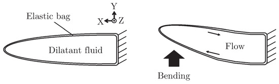
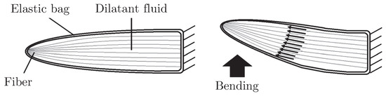
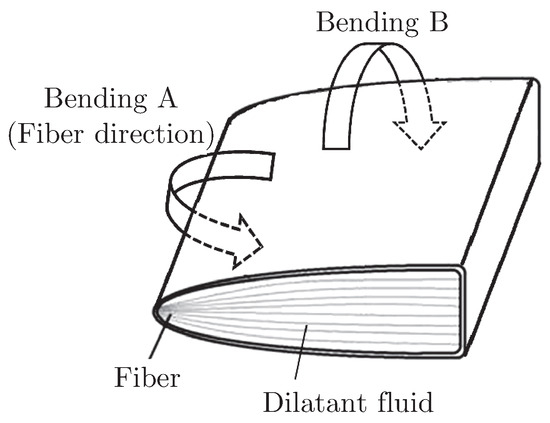
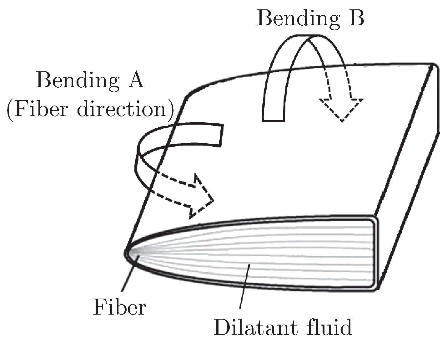
Dilatant fluid is one of the non-Newtonian fluids, whose viscosity increases as the shear rate is increased; it is also known as shear thickening fluid [5]. Figure 1 presents the concept of a viscoelastic fin containing dilatant fluid. When the bending is applied to the fin, dilatant fluid flows inside the elastic bag and the shear rate of fluid also increases. As the bending applied to the fin becomes faster, the shear rate and viscosity of the dilatant fluid becomes greater, as does the resistance to the bending of the fin. This means that the apparent bending stiffness of the fin is increased. If the fibers are added to the dilatant and bending is applied to the fin (Figure 2), fibers slide against each other and the increase of the shear rate and viscosity of the dilatant fluid is promoted by the increase in the shear gradient, which narrows the distance between each fiber. Generally, dilatant fluid is the suspension, while fibers act to maintain fluid and avoid the precipitation of particles in suspension. Figure 3 presents the concept of two directions of the bending applied to the fin. When the bending is applied in the direction of fiber orientation (Bending A), the increase in stiffness is greater than that when the bending is applied perpendicular to the fiber orientation (Bending B). These characteristics will indicate the anisotropic bending speed dependence of stiffness. Furthermore, the bending speed dependence of stiffness can be controlled not only by the properties of dilatant fluid, but also the density of fiber. Some applications use non-Newtonian fluids for mechanical parts, but an external source of energy is required for the control [6]. Therefore, this fin is a novel smart structure, which does not need an outer energy to control stiffness.
Figure 1.
Concept of a viscoelastic fin containing dilatant fluid.
Figure 2.
Concept of a viscoelastic fin containing fiber composite dilatant fluid.
Figure 3.
Concept of two directions of bending applied to the fin containing fiber composite dilatant fluid.
2.2. Structure of a Viscoelastic Fin Containing Fiber Composite Dilatant Fluid
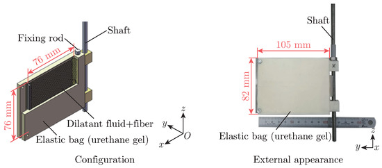
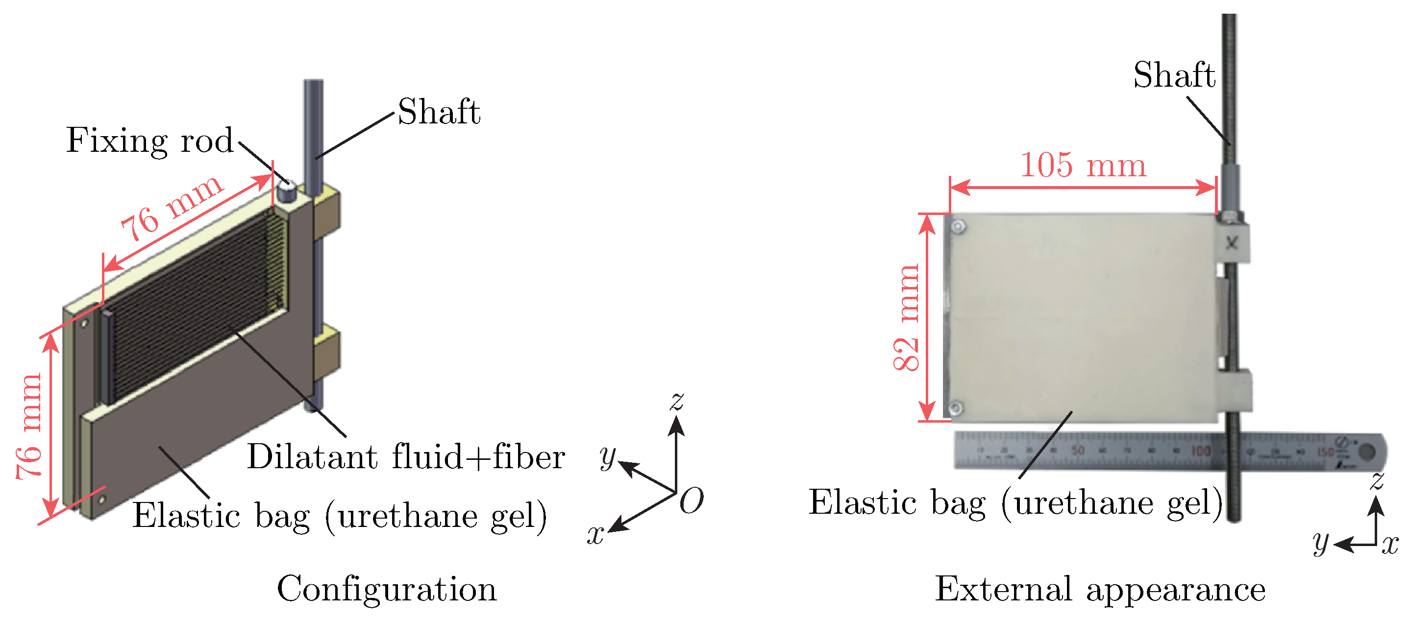
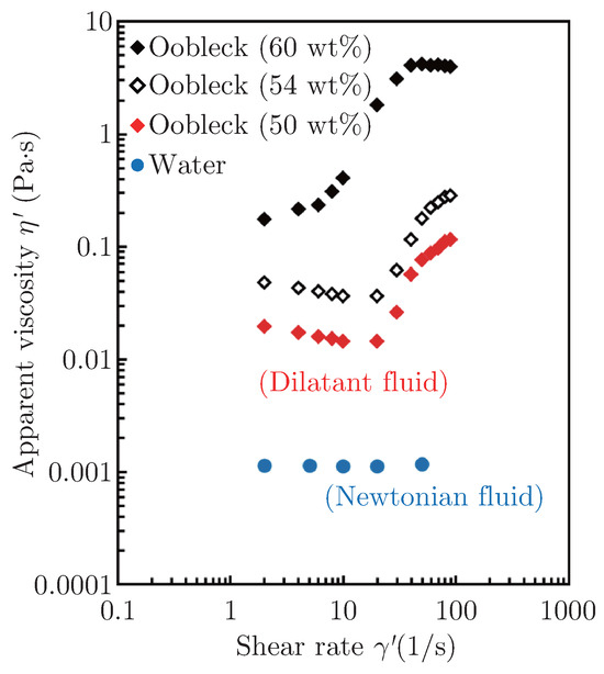
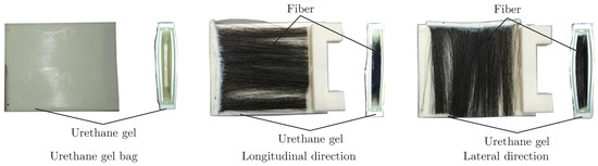
Figure 4 shows the configuration and external appearance of the viscoelastic fin containing fiber composite dilatant fluid. This fin consists of an elastic bag, dilatant fluid and fibers. A shaft is attached to rotate the fin. The elastic bag is made of soft urethane gel (Asker c-scale hardness: 40). Oobleck (the aqueous suspension of potato starch) was used as the dilatant fluid [7]. Figure 5 shows the relationship between apparent viscosity and the shear rate of fluid measured by the rotational rheometer. The apparent viscosity of oobleck increases suddenly from a certain shear rate. We used the oobleck of 60 wt% of potato starch for the fin. As the fiber for the fin, animal fiber (horse hair as the paintbrush and craft) was used. The average diameter and resistance of the incipient tension of the fiber are 110 µm and 2 N/tex, respectively. The fiber content in the bag is 6.0 vol%. Figure 6 depicts the inside of the fin. To investigate the anisotropy of stiffness, two fiber orientation (longitudinal and lateral directions) were set for the experiment. To evaluate the stiffness characteristics of the bending speed dependence of the stiffness of the fin, we also made a fin without fiber and different fluid (water as the Newtonian fluid).
Figure 4.
Configuration and external appearance of the viscoelastic fin.
Figure 5.
Relationship between apparent viscosity and shear rate of fluid.
Figure 6.
Inside of the fin.
3. Bending Test
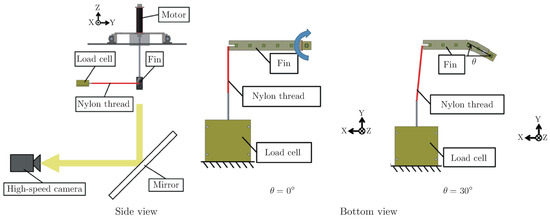
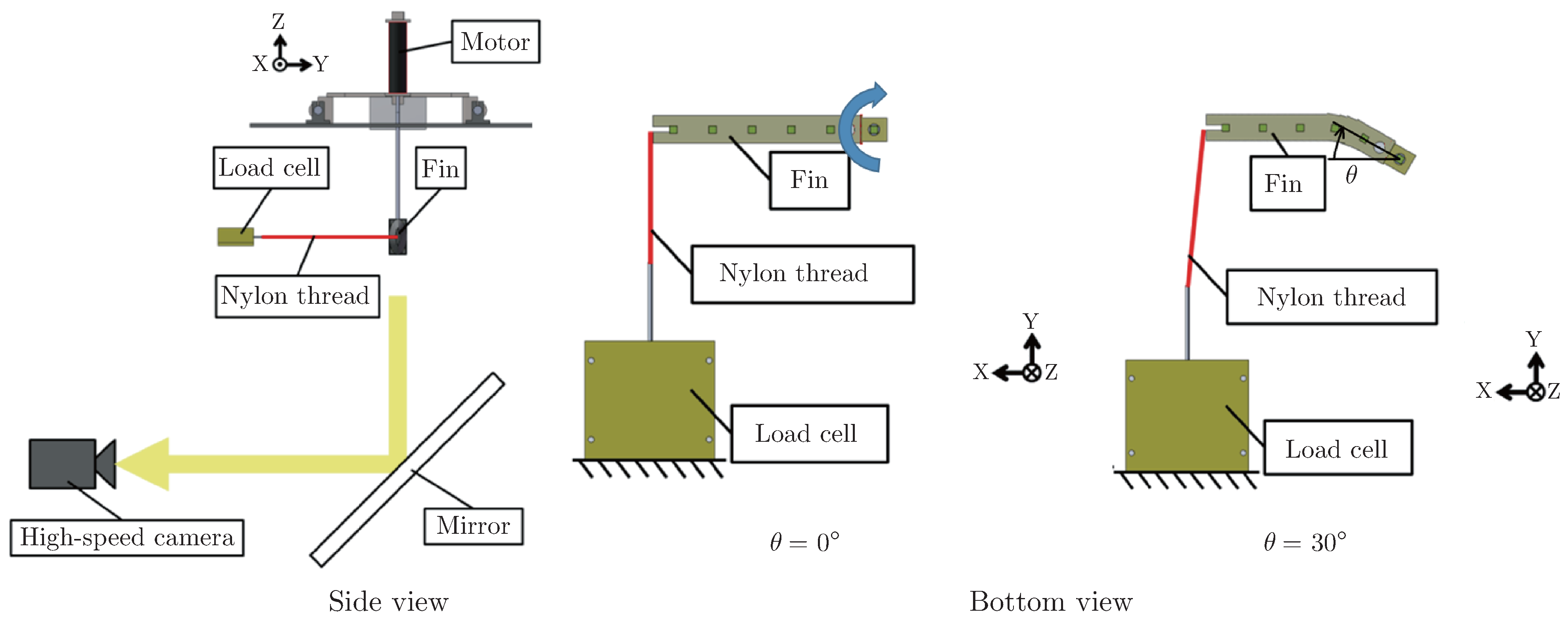
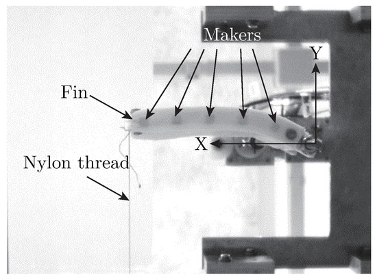
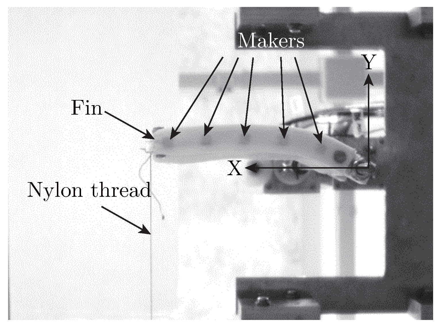
Figure 7 shows the experimental system for the bending test to evaluate the bending speed dependence of stiffness in the fin. The computer-controlled servo motor rotated the fin. The top of the fin was connected to the load cell by nylon thread. When the fin was rotated, it was bent and the tension force of nylon thread was measured by the load cell. The measured force was recorded as the bending resistance of the fin, which corresponded to the apparent dynamic stiffness. The rotation of the fin was the sinusoidally yawing motion: i.e., if the load cell is not connected (free motion without constraint by nylon thread), the fin is moved on account of the oscillating motion (when the yawing angle is 0°, the angular velocity is at the maximum; when the yawing angle is at the maximum, the yawing speed is zero for changing the rotating direction). We also observed the bending behaviour of the fin from the video taken by the high-speed video camera. The video picture of the fin when yawing angle θ = 30° is shown in Figure 8. We added five markers to the underside of the fin. The positions of markers were digitized using two-dimensional motion analysis software.
Figure 7.
Experimental system for the fin bending test.
Figure 8.
Video picture of the underside of the fin when θ = 30° (Oobleck + Fiber (Longitudinal direction), ω = 1.29 rad/s).
As the experimental condition, maximum yawing angle θmax was 30° and the average yawing angular velocity of the fin ω was changed from 0.57 to 1.29 rad/s. Initially, the fin was moved from −30° of the yawing angle. A tension force appeared at 0° from the yawing angle. Yawing and measurement were performed three times under one experimental condition. Bending resistance force F for the evaluation was calculated as the ensemble average of measured data on the bending resistance force for three yawing performances.
4. Results and Discussion
4.1. Bending Behavior of Fin
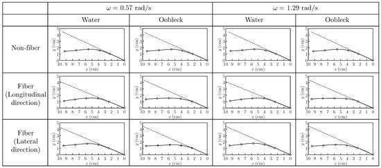
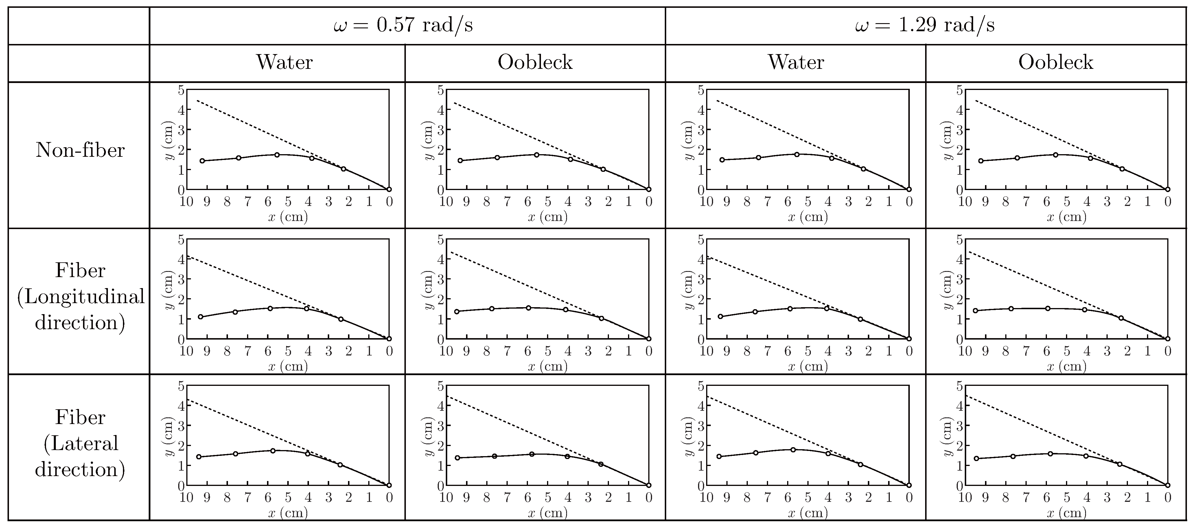
Figure 9 shows the positions of markers which represent the bending behavior of fin when θ = 30° (maximum angle). Greater bending of fins appeared around x = 4 cm. The position of the top marker of the fin was moved. This is accounted for the greater bending of the fin and slight sagging of nylon thread when θ = 0°. There are no significant differences in all fins and yawing angular velocities. However, the bending of the fins containing water was slightly greater than those of fins containing oobleck. This is explained that the fins containing water are softer than the fins containing oobleck.
Figure 9.
Behavior of fins when θ = 30°.
4.2. Bending Resistance Force of Fin
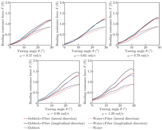
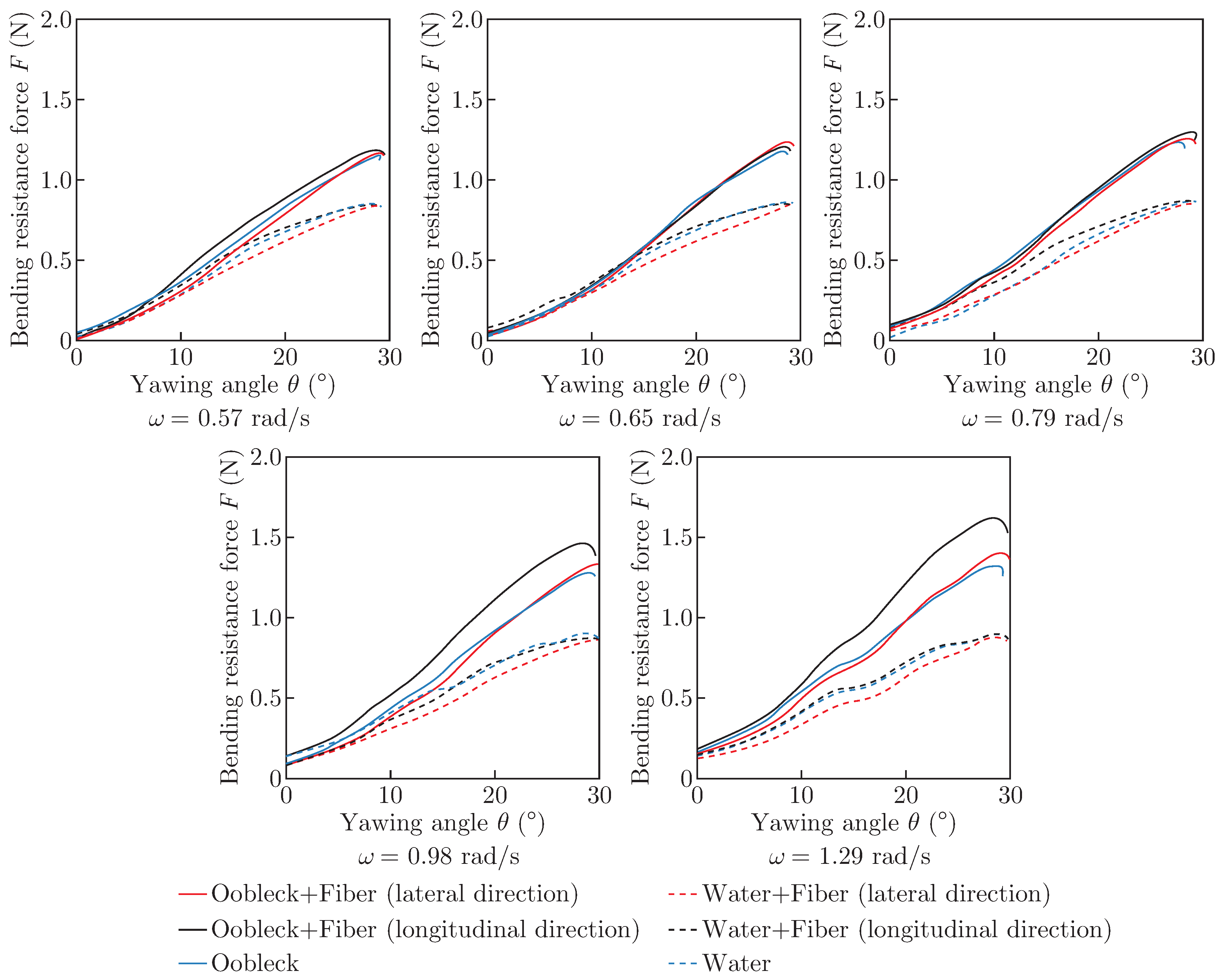
Figure 10 presents the bending resistance force of fin F in one yawing motion. F is increased with the yawing angle. When the yawing angle is 0°, a small sudden increase in F appears, especially for a higher average angular velocity. This is caused by the tension of nylon thread, which began to be applied from this angle under the condition of the maximum rotational angular velocity of the fin. When the maximum angle of the yawing angle (θ = 30°) is reached, F is slightly decreased. This is caused by the deceleration of the rotational angular velocity of the fin. In the case of the slower average angular velocity, F almost the same till is almost the same till approx. 10° of yawing angle and F for the oobleck increases more significant than that for water from that yawing angle. As the average angular velocity increases, F for the oobleck is higher than that for water from the smaller yawing angle, and the difference of F between oobleck and water becomes greater.
Figure 10.
Bending resistance force of fin F in one yawing motion.
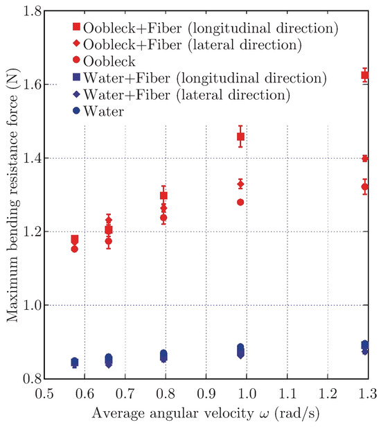
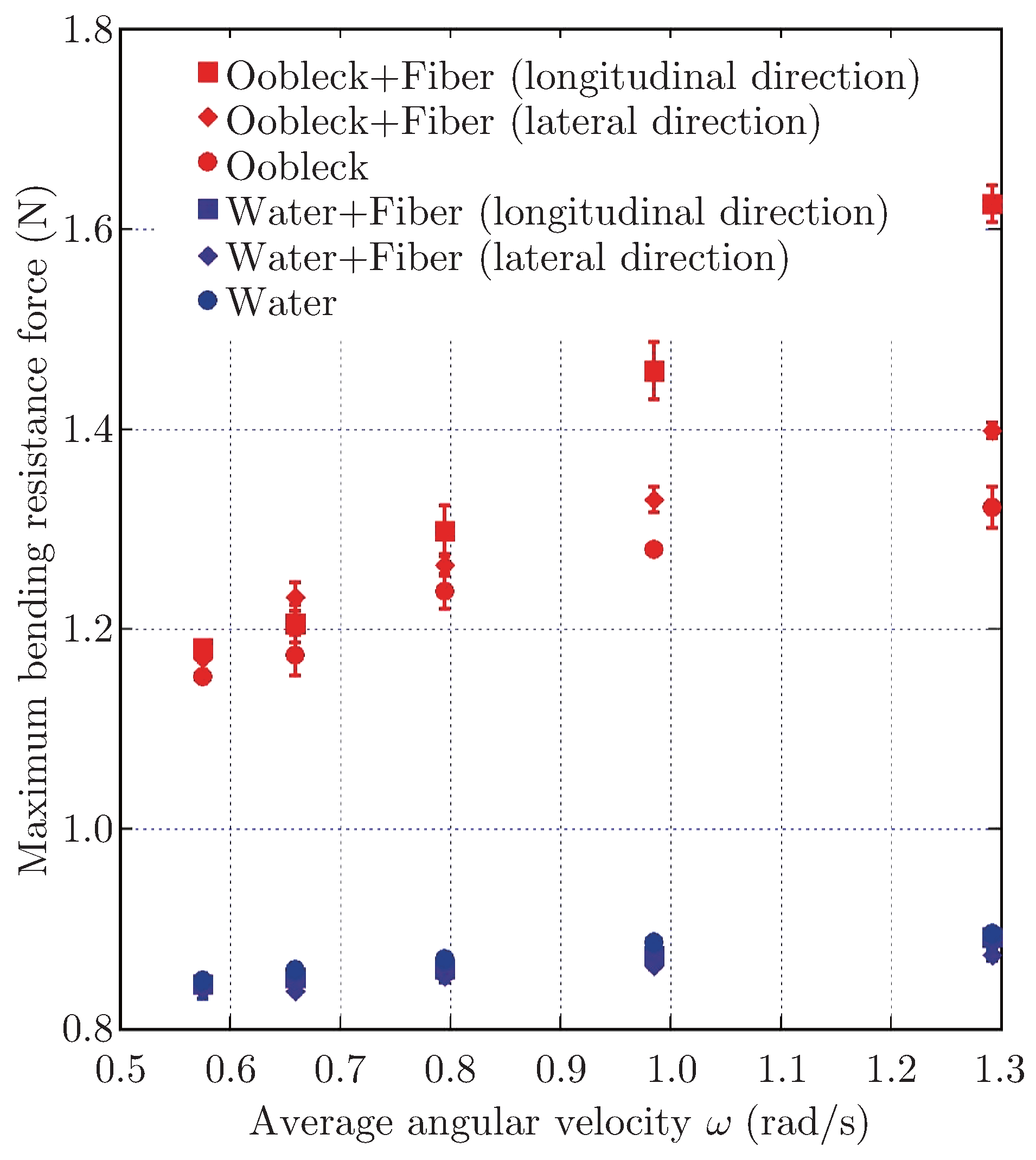
To evaluate the difference in fluid, fiber orientation and angular velocity, we noticed the maximum value of the bending resistance force of the fin. Figure 11 shows the relationship between average angular velocity ω and maximum bending resistance force Fmax. Error bars indicate the standard deviation (n = 3). For the water, Fmax was almost constant for the changing average angular velocity and the existence of fiber, while the standard deviations of Fmax were tiny. This phenomenon is explained by the fact that, since water was the Newtonian fluid, viscosity did not change by changing the shear rate; consequently, the stiffness of the fin was also constant when changing the average angular velocity. Fmax for the oobleck was greater than that of water at any angular velocity. This was caused by the greater viscosity of oobleck. Fmax increased as the average angular velocity increased. This increase represents the characteristics of dilatant fluid: viscosity was increased by the increase in shear rate induced by the greater deformation rate. Fmax increased further due to the existence of fiber. In particular, the fin with the longitudinal direction of fiber showed a remarkable increase of Fmax. This phenomenon meant that the increase in shear rate along the fiber direction was effective for the increase in bending resistance force. This result shows that the orientation angle of fiber was also an essential factor in controlling the anisotropy of the bending speed dependence of stiffness.
Figure 11.
Relationship between average angular velocity ω and maximum bending resistance force Fmax.
5. Conclusion
We have developed a viscoelastic fin containing fiber composite dilatant fluid. Although the fin did not the significant particular difference of bending behavior while the bending test, we confirmed that the bending speed dependence of stiffness appeared by using dilatant fluid, while the longitudinal direction of fiber promoted the increase in stiffness. We also found the orientation of fiber could be act as a control parameter for the anisotropy for the bending speed dependence of stiffness.
Generally, the matrix of “fiber composite material” is as solid as reinforced material in terms of light weight and greater toughness. The matrix that we proposed is fluid; therefore, we can say that this is “fiber composite fluid”. This developed fin is a highly functional structure, which can adapt to the demands of changing optimum stiffness concerning deformation speed.
In terms of future study, we will investigate the more specific relationship between the bending speed dependence of stiffness and the dilatant fluid property, i.e., fiber. Furthermore, the utilization of more durable dilatant fluid and fiber is required.
References
- Morikawa H, Isshiki N, Sawada T, Motozawa Y. The Study on a Propulsion System by Fin Stroke. J Marine Eng Soc Japan: 1983; 18-5: 393-400.
- Kobayashi S, Nakabayashi M, Morikawa H. Bioinspired Propulsion Mechanism in Fluid Using Fin with Dynamic Variable-effective-length Spring. J Biomech Sci Eng: 2006; 1-1: 280-289.
- Kobayashi S, Morikawa H, Soyano H, Nakabayashi M. Propulsion Mechanism in Fluid Using Variable-stiffness Fin with Torsional Rectangular Elastic Plates. Int J Offshore and Polar Eng: 2013; 23-3: 172-177.
- Sugiyama K, Kobayashi S. Propulsion Characteristics of Bio-inspired Aquatic Propulsion Mechanism Using Fiber Composite Viscoelastic Fin Filled with Dilatant fluid. Proc 2017 JSME Conference on Robotics and Mechatronics: 2017; 2A1-L05.
- Kamibayashi M, Ogura H, Otsubo Y. Shear-thickening Flow of Nanoparticle Suspensions Flocculated by Polymer Bridging. J Colloid and Interface Science: 2008; 321: 294-301.
- Komatsuzaki T, Iwata Y, Ringe H, Kawagoshi K. Development of a Dynamic Vibration Absorber with Variable Stiffness Property Using Magneto-rheological Elastomer. Trans Japan Soc Mech Engineers, Series C: 2013; 79-806: 3680-3690.
- Crawford NC, Popp LB, Johns KE, Caire LM, Peterson BN. Shear Thickening of Corn Starch Suspensions: Does Concentration Matter? J Colloid and Interface Science: 2013; 396: 83-89.
© 2019 Textile Bioengineering and Informatics Society. This article is an open access article distributed under the terms and conditions of the Creative Commons Attribution (CC BY) license (https://creativecommons.org/licenses/by/4.0/).