Abstract
The effect of micro patterning of cemented carbide surface using nanosecond diode pumped solid-state pulsed laser on the strength of induction brazed carbide and steel joints has been investigated. Surface patterns increase the total surface area of the joint and, for an originally hydrophilic surface, increase the wettability of a liquid on a solid surface such that, instead of building droplets, the liquid spreads and flows on the surface. Microcomputed tomography (µ-CT) was used to observe the filler/carbide interface after brazing and to analyze the presence of porosity or remnant flux in the joint. Microstructures of the brazed joints with various surface patterns were analyzed using scanning electron microscopy. The strength of the joints was measured using shear tests. Results have shown that the groove pattern on the surface of carbide increases the joint strength by 70–80%, whereas, surface patterns of bi-directional grooves (grid) reduced the joint strength drastically. Dimples on the carbide surface did not show any improvement in the strength of the brazed joints compared to samples with no surface pattern.
1. Introduction
Geometrically defined polycrystalline diamond (PCD) saw tips with a backing layer of cemented carbide (WC-Co) represent an alternative to sintered diamond blades with geometrically undefined cutting edges for sawing of natural stones like granite, marble etc. [1,2,3]. It has been shown that using a high negative rake angle on the saw tips, which is advantageous for reduction of tool wear, results in failure in the brazed joints of the saw tips [1]. The saw tips used particularly on the band saws, because of their small size, cannot be screw clamped to the tool body as in the case of a typical indexed milling cutter. Brazing is the most common process of joining carbide or carbide backed PCD tips to the body of the saw blades. Most of the sawing tools are still brazed in an air atmosphere with an oxy-acetylene flame or an induction coil. However, the strength of the brazed joints varies widely because of various factors such as filler metal composition [4], gap thickness [5], brazing time and temperature [6], surface roughness [7], surface chemical composition [8,9,10], cleanliness of the surface, incomplete removal of oxides and inclusions of flux, presence of porosity, and thermal cracks [11].
Tungsten carbide, especially the grades with high hardness and low binder content, shows poor wettability by most brazing alloy standards, especially when brazing in air [12,13]. The filler metal forms a metallic bond with the metal (binder) present on the surface and for carbide grades containing low binder content, the surface contains very little binder for the filler metal to form a bond with. The state-of-the-art solution is the galvanic coating of the carbide surface with a metal usually cobalt or nickel (metalizing). However, due to the health and safety issues the electrolytes used in the process are classified as hazardous substances by the European Union (EU) and their production and application will be gradually limited [14,15,16]. A novel approach for enhancing the wettability of the surfaces is the process of “laser structuring”. Whereby the surface of the material is ablated using Nano-, pico-, or femtosecond pulsed lasers so as to generate specific surface textures to achieve desirable optical, electrical or mechanical characteristics. Recent studies have shown the potential of this technique to improve the wettability of ceramic [17] as well as metallic materials [18]. Zhang et al. used this technique to improve wettability characteristics (and in turn the joint strength) of Al2O3 surface for brazing with stainless steel under vacuum [19]. It was shown that the surface grooves not only cause mechanical pinning at the ceramic/filler interface, but also result in periodic tensile and compressive residual stress peaks, which hinder crack propagation. Similarly, Otero et al. generated grooves and dimple structures on a Nimonic N75 alloy surface and studied the effect of surface structures on wettability and joint strength [20]. The results showed a 2–2.5× increase in the shear strength of brazed joint. However, this technique has not been tried on tungsten carbide/steel brazed joints and specifically air atmosphere brazed joints. This work is intended to enhance the strength of the uncoated tungsten carbide/steel brazed joints by structuring the surface of the carbide using a short-pulsed laser. Furthermore, computer tomography is used as a non-destructive testing approach to assess the quality of the brazed joints.
Pulsed Laser Ablation
Laser ablation refers to the material removal by using short high-intensity laser pulses as the heating source. Pulsed lasers produce shorter bursts of energy, which result in much higher peak energy levels than a continuous wave (CW) laser source [21]. Pulse durations may be in micro- or nanoseconds (short pulses) or in pico- and femtoseconds (i.e., ultra-short pulses).
For pulse durations above 10 picoseconds (ps), the ablation process consists of heat conduction, melting, evaporation and plasma formation as shown in Figure 1 [22]. Pulse durations of less than 10 ps (ultrashort pulses) are shorter than the time required for electrons, which absorb the energy of the photons, to transfer their energy to the lattice. Therefore, ablation processes with ultrashort pulses involve no melting and virtually no heat affected zone [23]. Although ultrashort laser ablation is extremely precise, the ablation rate is significantly lower than with laser ablation in a nanosecond regime, which allows the highest ablation efficiency [22].
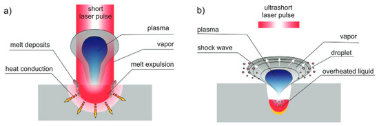
Figure 1.
Pulsed laser beam and matter interaction (a) short pulse laser (µs, ns)—matter interaction; (b) ultrashort pulse (ps, fs) beam-matter interaction [22].
2. Materials and Methods
For this work, tungsten carbide (WC-8%Co) type K-20F (ISO K20-K30) with a grain size of 0.7 µm from HHT-Hartmetall, Germany, was used in a cylindrical form with a 9 mm diameter and 10 mm height. These were brazed on to 20 mm diameter and 15 mm high cylinders made of S235JR steel. Both carbide and steel parts were sand blasted using 10 µm corundum particles and then cleaned in an ultrasonic bath of ethanol. Sand blasting was necessary as the carbide surface in an ‘as-delivered’ condition was oxidized and had a pale-yellow tint most likely due to the presence of tungsten oxide on the surface. The roughness of the blank surface after sand blasting and ultrasonic cleaning was measured optically using white light interferometry and the roughness parameters were found to be Ra 3 µm and Rz 12.3 µm. Three classes of surface structures namely the grooves, grid, and holes were created using a nanosecond pulsed laser source (Section 2.1). For each surface type, four samples were produced and were used according to Table 1. Samples with a blank surface were only used for shear tests for comparison.

Table 1.
Experimental plan for four samples of each type of surface structure.
2.1. Laser Surface Structuring
Three classes of surface structures, namely the grooves, grid, and holes, were created using a nanosecond pulsed laser. The samples with blank (unstructured) surface were used as control samples for comparison. Clean-Laser CL50 with 2D scanning optic of the “STAMP” series of CleanLaser GmbH, Germany was used for this work. The laser source is a diode pumped solid-state laser with average power of 50 Watt and maximum pulse frequency of 200 kHz. The laser parameters used for patterning the carbide surfaces are given in Table 2. The parameters were selected in order to obtain the shortest possible pulse duration, which, for the used laser system, varies between 100 ns and 200 ns with the pulse frequency.
Table 2.
Laser parameters for surface structuring of cemented carbide.
The prepared surfaces were cleaned in an ultrasonic bath of ethanol and were examined under a white light interferometer to assess the surface topography. The width of the grooves, shown in Figure 2a and the grid (Figure 2b) was between 100 µm and 150 µm. The diameter of the holes (Figure 2b) was on average 150 µm with a depth of 500 µm. The distance between the grooves, grid, and the holes was kept at 600 µm.
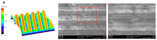
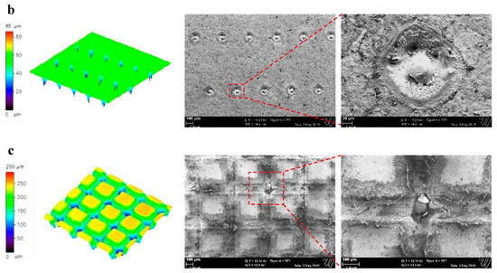
Figure 2.
3D White light interferometry (left) and SEM images (middle and right) of the structured carbide surfaces having (a) Grooves, (b) Holes and (c) Grid.
2.2. Brazing
The brazing filler used was Braze-Tec 4900 (ISO Ag449) silver-based filler having 49% silver and a mixture of copper, zinc, manganese, and nickel. The filler metal has a melting range from 680 °C to 705 °C and shear strength according to DIN EN 12797 of 250–300 MPa for a carbide/steel joint. The filler alloy was cut in 9 mm diameter circles from a band having 0.1 mm thickness and placed between the carbide and steel parts. A ceramic pin was used to hold down the carbide part in place while brazing, as shown in Figure 3.
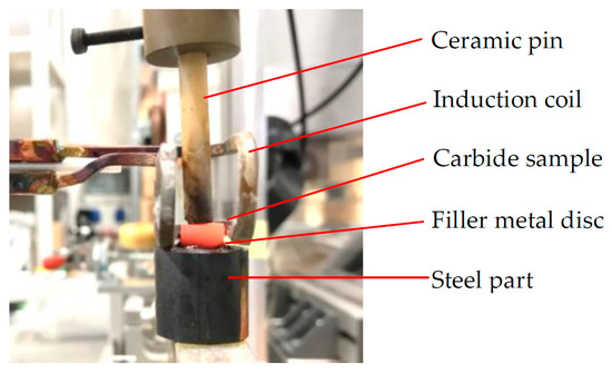
Figure 3.
Induction brazing joint assembly.
The heating source was an induction coil operating at a frequency of 30 kHz and 2 kW power. The power source of the induction heater was controlled with the thermometer output using a LabVIEW program. The working temperature was set at 720 °C and holding time at 5 s. BrazeTec special-h compound was used as the flux in the form of paste on both sides of the filler metal disc before brazing. The temperature was measured using an Optris infrared thermometer CT-laser 3M having a measurable range from 50 °C to 1800 °C with a spectral range of 2–3 µm. The laser of the thermometer was pointed at the carbide part slightly above the filler interface to avoid pointing the laser at bubbles formed due to flux.
2.3. Non-Destructive Testing of Brazed Joints Using Computer Tomography and Scanning Electron Microscopy
Non-destructive tests for the brazed joints include the ultrasonic tests, electrical resistance tests, x-ray or gamma ray radiography through the joint or computer tomography using x-rays [11]. In this work, computer tomography was used as the non-destructive test method. Computer tomography (CT), in principle, works in the same way as a 2d x-ray measurement whereby the x-ray source is located at one end and the detector on the other. As the x-rays pass through the workpiece, different materials transmit the radiation at different intensities and defects are seen as darker spots on the detector. In computer tomography, multiple x-ray images are taken at different planes using a rotary holder for the workpiece. The individual images are then overlapped such that a volume image is calculated to create a three-dimensional x-ray image of the object. The CT method of x-ray imaging gives a much greater resolution than film radiography, which enables finer defects to be detected. Furthermore, the location of the defects in the brazed joint for example whether porosity is on the carbide/filler side or the steel/filler side can be detected. Moreover, the slice-by-slice information could be obtained through micro-CT without having to cut the sample. Disadvantages are longer test times and large data sets [11].
A Zeiss xradia 520 Versa, shown in Figure 4, with a maximum X-ray tube voltage of 160 kV was used for radiographic testing. With an image resolution between 0.5 µm and 200-µm, the µ-CT is well suited for the task. For the measurements, a tube voltage of 140 kV and a source output of 10 W were used. The distance between the source and the measuring objects was 50 mm, while between the source and the detector was 120 mm. For these distances, a voxel size of 28 µm could be achieved with a 0.4X objective. For a high-quality scan, 1601 projections over a 360° angle were taken. The exposure time was 7 s.
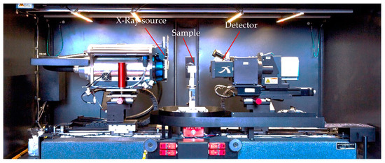
Figure 4.
Zeiss xradia 520 Versa used for microcomputed tomography.
In addition, one of the brazed samples for each of the surface classes was cut (using wire erosion technique) through the center, ground, polished and observed under the Zeiss Ultra Plus scanning electron microscope (SEM). The sample with grooves was cut perpendicular to the direction of the grooves and that of the grid was cut at 45° to the direction of the grooves.
2.4. Shear Tests
Push-type shear tests were performed on three samples of each class of surface structure on a Zwick-Roll universal testing machine using the fixture shown in Figure 5. The v-shaped punch had 2 mm thick tungsten carbide plates glued on to it for wear resistance. The brazed samples were sand blasted at the edges of the brazed joint to provide a flat contact surface for the punch so that a pure shear loading at the brazed joint may be achieved. The punch moved downwards at a constant speed of 1 mm/minute. No pre-load force was used. The brazed samples, which had grooves on the surface, were loaded in the direction perpendicular to the direction of the grooves and those with grid structure at 45°. The loading direction was chosen in accordance with the results given in [19] whereby the load direction perpendicular to the grooves increased the shear strength by nearly two times compared to the parallel direction. For the grid structure, a 45° direction was chosen to avoid loading the sample directly parallel to the grooves in either direction. This was done in order to achieve a mechanical advantage as the grooves induce mechanical interlocking of the faying surfaces when loaded perpendicular to their axes. Peak force before fracture divided by the surface area of the brazed joint was calculated as the shear strength of the joint.
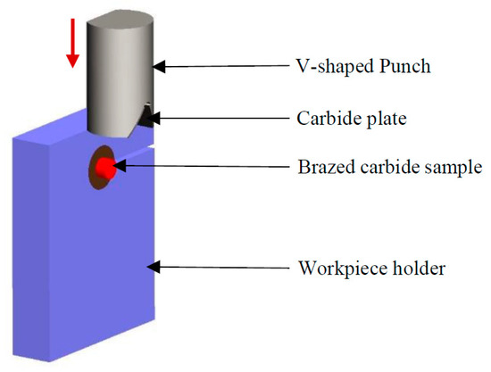
Figure 5.
Test rig used for shear tests of the brazed samples.
3. Results and Discussion
The µ-CT images of the interface between carbide and filler are shown in Table 3. The darker regions indicate the porosity and voids. The first observation is a well-defined outer ring almost completely free of porosity for every sample. This is most likely due to the cooling cycle, whereby the outer region is cooled first and is solidified thereby stopping the gas bubbles in the core region from escaping.
Table 3.
µ-CT images of the carbide/filler metal interface for the four surface structures.
The Sample 1 of the blank surface in Table 3 shows well distributed porosity consisting of small air bubbles. In contrast, Sample 2 shows clumped porosity. This is most probably due to slower cooling in case of Sample 2 compared to Sample 1. As multiple air bubbles try to escape through the same openings in the molten outer region the region solidifies, resulting in air bubbles being clumped together. For Sample 2 of the blank surface, the plane of the filler layer was not parallel to the x-ray travel axis and hence for any one slice there is a dark (out of focus) and a bright (in focus) region. In case of carbide surface having holes, the observed interface of carbide and filler metal appears to be rough and uneven especially in the case of Sample 2. This indicates lack of bonding at the interface, also seen in the SEM image of the cross section in Figure 7d.
For the grooves, the porosity aligned along the grooves and probably resulted in anisotropy in the brazed joint, such that the strength of the joint parallel to the grooves is lower than the strength perpendicular to them, as shown by [19]. The µ-CT analysis of the two samples having grid structure shows a lack of bonding between the filler and carbide. For Sample 1 of the grid surface, the surface pattern of the carbide could be seen across the filler layer implying that the filler layer is very thin.
Results of the shear tests for three samples of each surface type are shown in Figure 6. The maximum shear strengths of about 250 MPa were obtained for the samples having grooves in the direction perpendicular to the applied force. Holes or dimples on the surface have shown little to no effect on the strength of the brazed joints compared to the blank surface, whereas the grid structure has resulted in very low joint strengths of on average 25 MPa. For blank, holes and grooves the fracture was partly at the carbide/filler interface and part within carbide. For the grid, all three samples fractured completely at the carbide/filler metal interface.
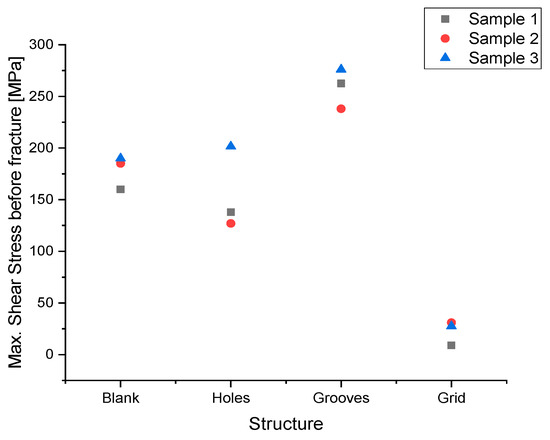
Figure 6.
Shear strengths of the carbide/steel brazed joints having no structure (blank), holes, grooves and grid patterns on carbide surface.
An SEM image of cross section of the brazed sample with carbide having holes on the surface is show in Figure 7a. The filler metal layer has a thickness of around 80 µm after brazing. It is observed that due to the holding pressure applied using the ceramic pin, as shown in Figure 3, a significant amount of filler is pressed out of the interface towards the sides. Figure 7c shows a high-resolution image of the cross section of the hole on the carbide side (marked as region 1 in Figure 7a). A significant amount of tungsten carbide (WC) is seen in the hole due to the re-solidification of the melt pool and deposition of the tungsten carbide during ablation with nanosecond laser. This observation is confirmed by the energy dispersive X-ray spectroscopy (EDS) analysis of the cross section as shown in Figure 7d as a color map for various elements. The yellow color represents tungsten, which in this case is present in the form of tungsten carbide (carbon cannot be detected by the EDX method). This is in agreement with the SEM images of the holes shown in Figure 2b,c with dome shaped central area in hole. Traces of cobalt binder is seen as green colored regions at the interface. Figure 7b shows the cross section of a section of joint without a dimple. The presence of pools of remnant flux is seen at the filler/steel interface. Figure 7e shows the carbide/filler interface at a higher resolution. Lack of bonding is clearly seen at the interface with the carbide surface having micro cracks on the surface. The exact reason for this lack of bonding at the interface is unclear however, authors are of the opinion that this is due to the lack of binder metal on the surface. The filler layer itself is very homogenous with the secondary eutectic phase evenly distributed across the layer.
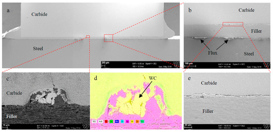
Figure 7.
SEM image of (a) complete cross section of a sample 4 of brazed joint with holes on carbide surface (b) Cross section of surface hole (c) Cross section of region without holes showing remnant flux (d) energy dispersive X-ray spectroscopy (EDX) color mapping of hole (e) carbide/filler interface.
In case of the carbide surface having grooves, the porosity is aligned in the direction of the grooves as seen in Table 3. An SEM image of the cross section of a groove in the brazed joint is shown in Figure 8. Remnant flux is also seen inside the porosities. In addition, large voids with pockets of remnant flux were observed within the filler layer as seen in Figure 8b. Fine hairline cracks can also be seen at the tip of the V-shaped grooves formed due to rapid local heating. The presence of voids and porosity indicates lack of flow of filler metal and lack of channels for the gases to flow out of the melt zone. This necessitates the use of longer holding time at the brazing temperature. Figure 8c shows the interface between filler and carbide. In addition, the filler layer itself contains small porosities shown as black colored spots again indicating the lack of channels for gases to flow out of the melt zone. In contrast to Figure 7d, the interface is smooth and the secondary phase in the filler metal is segregated at the interface and is shown as a darker region in the filler layer. The authors are of the opinion that the smoother interface is due to lesser oxide content on the surface of the carbide which may be related to longer ablation cycles required to form grooves on the surface. However, further research is needed to establish this point.
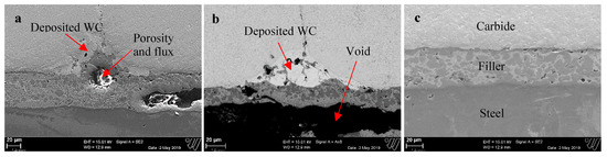
Figure 8.
(a) Cross section of a groove (b) Groove with redeposited tungsten carbide and large void in the filler layer and (c) brazed region without grooves.
An SEM image of the cross section of Sample 4 of the grid category is shown in Figure 9a,b. A much thinner filler layer of less than 20 µm is observed in Figure 9a in contrast to a thickness of about 100 µm in the case of holes (see Figure 7c), and about 40 µm (see Figure 8a,c). A plausible reason for this reduction is a large increase in the surface area due to the grid compared to that with holes or with grooves on the surface. Additionally, in Figure 9a, the filler/carbide interface shows granular WC particles dispersed in the filler layer. They reduce the extent of the metallurgical bonds between the filler metal and the binder of the cemented carbide. These particles most likely result from deposition of the ablated WC particles on the carbide surface once the laser is moved away. The laser likely breaks the bond between WC particles and the Cobalt binder such that the individual granulates are very weakly bound to the carbide surface. However, these could not be removed by sand blasting and ultrasonic bath cleaning. During brazing, the higher temperature caused the bonds to weaken and thus individual WC grains dispersed to an extent in the filler layer. This is particularly critical for the grid surface pattern as the laser is moved twice the number of times across the surface as in case of grooves. This finding corroborates the rough SEM images of the grid surface seen in Figure 2. In Figure 9b, a density contrast image of the cross section of a groove is shown. Large gas pores are observed close to the grooves, and inside the grooves remnant flux is seen within the pores.
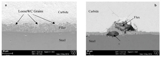
Figure 9.
SEM micrograph of brazed sample with grid pattern on carbide showing (a) loose tungsten carbide (WC) grains at the filler/carbide interface (b) Porosity and remnant flux in the grooves.
4. Conclusions
- Carbide surfaces consisting of grooves perpendicular to the direction of load have been shown to improve the strength of the induction-brazed joints of cemented carbide and steel by up to 80% compared to unstructured carbide surface. This result affirms the results of shear strength measurement of Al2O3/304 stainless steel joint containing grooves on the ceramic component obtained by femtosecond laser ablation, as presented in [19]. However, the extent of the increase of strength is only 80% compared to 250% for the authors of [19]. One of the reasons is the application of a nano-second pulsed laser instead of a femtosecond pulsed laser, which markedly reduced the quality of the laser ablated surface due to melt zones and deposition, as shown in Figure 1, thus hindering the molten filler metal from spreading and flowing smoothly. Secondly, the authors of [19] brazed the ceramic samples under vacuum, thereby eliminating the requirement of flux for brazing.
- The bi-directional grooves or the grid structure reduced the joint shear strength drastically from about 175 MPa in blank surface condition to only 25 MPa. The SEM images of the cross section showed that the reason is primarily loose tungsten carbide grains on the carbide surface that deposit on the surface during laser ablation and during brazing, hindering a metallurgical bond between the binder metal of the cemented carbide and the filler metal.
- This work has shown that the surface structuring or patterning of a cemented carbide surface with pulsed laser ablation can lead to a significant increase in the strength of brazed joints. However, for greater strength, there is a lower benefit in terms of the cost ratio, and ultrashort laser pulses (pulse duration < 10 ps) must be used for surface structuring and brazing should be performed without flux either under vacuum or in a controlled atmosphere.
Author Contributions
Conceptualization, methodology, writing and editing of draft manuscript: A.A.; Micro-computer tomography analysis: I.K.; Supervision and review of manuscript: S.B.
Funding
This research was funded by the Federal Ministry of Education and Research (German: Bundesministerium für Bildung und Forschung) ‘BMBF’ of Germany under the project ‘Development of a production facility for resource and energy efficient manufacturing of natural stone plates’ (German: Entwicklung einer Produktionsanlage zur ressourcen- und energieeffizienten Plattenherstellung aus Naturwerkstein) (Acronym: Re2RockCut), grant number 02P14A060.
Conflicts of Interest
The authors declare no conflict of interest.
References
- Reichenbächer, H. Trennen mineralischer Werkstoffe mit geometrisch bestimmten Schneiden; Kassel University Press: Kassel, Germany, 2010; pp. 135–137. [Google Scholar]
- Böhm, S.; Scherm, W.; Reichenbächer, H. Steinbearbeitung mit geometrisch bestimmter Schneide aus PKD. Diamant Hochleistungswerkzeuge. dihw Magazin 2011, 3, 32–35. [Google Scholar]
- Böhm, S.; Schwarte, S.; Heise, C. Bearbeitung von Stahlbeton mit geometrisch bistimmter Schneide aus PKD. Diamant Hochleistungswerkzeuge. dihw Magazin 2012, 4, 28–35. [Google Scholar]
- Kaiwa, K.; Yaoita, S.; Sasaki, T.; Watanabe, T. Effects of Ni and Co Additions to Filler Metals on Ag-Brazed Joints of Cemented Carbide and Martensitic Stainless Steel. Adv. Mater. Res. 2014, 922, 322–327. [Google Scholar] [CrossRef]
- Hasanabadi, M.; Shamsipur, A.; Sani, H.N.; Omidvar, H.; Sakhaei, S. Interfacial microstructure and mechanical properties of tungsten carbide brazed joints using Ag-Cu-Zn + Ni/Mn filler alloy. Trans. Nonferrous Met. Soc. China 2017, 27, 2638–2646. [Google Scholar] [CrossRef]
- Jiang, C.; Chen, H.; Wang, Q.; Li, Y. Effect of brazing temperature and holding time on joint properties of induction brazed WC-Co/carbon steel using Ag-based alloy. J. Mater. Process. Technol. 2016, 229, 562–569. [Google Scholar] [CrossRef]
- Suezawa, Y.; Izui, H. Effects of Surface Roughness of Base Metals on the Residual Stress of Filler Metals at Brazed Joints. Mater. Sci. Forum 2002, 404–407, 611–616. [Google Scholar] [CrossRef]
- Useldinger, R.; Tillmann, W.; Osmanda, A.; Yurchenko, S.; Magin, M. Strength properties of induction based cermets. In Proceedings of the 17th Plansee Seminar 2009, International Conference on High Performance P/M Materials, Reutte, Austria, 25–29 May 2009. [Google Scholar]
- Chen, H.; Feng, K.; Xiong, J.; Guo, Z. Characterization and stress relaxation of the functionally graded WC–Co/Ni component/stainless steel joint. J. Alloys Compd. 2013, 557, 18–22. [Google Scholar] [CrossRef]
- Zhang, X.; Huang, Z.; Liu, G.; Wang, T.; Yang, J.; Shao, H.; Qiao, G. Wetting and brazing of Ni-coated WC–8Co cemented carbide using the Cu–19Ni–5Al alloy as the filler metal: Microstructural evolution and joint mechanical properties. J. Mater. Res. 2018, 33, 1671–1680. [Google Scholar] [CrossRef]
- Sievers, N. Die elektrische Widerstandsmessung zur zerstörungsfreien Prüfung von Lötnähten am Beispiel von Hartmetall-Stahl-Verbunden. LWT-Schriftenreihe Band 15; 1. Auflage; LWT-Schriftenreihe 15; Vulkan: Essen, Germany, 2017; pp. 33–41. [Google Scholar]
- Thorsen, K.; Fordsmand, H.; Praestgaard, P. Explanation of wettability problems when brazing cemented carbides. Weld. J. (Miami) 1984, 63, 308–315. [Google Scholar]
- Mirski, Z.; Piwowarczyk, T. Wettability of hardmetal surfaces prepared for brazing with various methods. Arch. Civ. Mech. Eng. 2011, 11, 411–419. [Google Scholar] [CrossRef]
- ECHA’s Current Activities on Restrictions – ECHA. Available online: https://echa.europa.eu/current-activites-on-restrictions (accessed on 28 March 2019).
- EU Commission Seeks Cobalt Salts Restriction. Available online: https://chemicalwatch.com/56054/eu-commission-seeks-cobalt-salts-restriction (accessed on 28 March 2019).
- German Electroplating Group Defends REACH Restriction Process. Available online: https://chemicalwatch.com/58355/german-electroplating-group-defends-reach-restriction-process (accessed on 28 March 2019).
- Granados, E.; Calderon, M.M.; Krzywinski, J.; Wörner, E.; Rodriguez, A.; Aranzadi, M.G.; Olaizola, S.M. Enhancement of surface area and wettability properties of boron doped diamond by femtosecond laser-induced periodic surface structuring. Opt. Mater. Express 2017, 7, 3389. [Google Scholar] [CrossRef]
- Huerta-Murillo, D.; García-Girón, A.; Romano, J.M.; Cardoso, J.T.; Cordovilla, F.; Walker, M.; Dimov, S.S.; Ocaña, J.L. Wettability modification of laser-fabricated hierarchical surface structures in Ti-6Al-4V titanium alloy. Appl. Surf. Sci. 2019, 463, 838–846. [Google Scholar] [CrossRef]
- Zhang, Y.; Zou, G.; Liu, L.; Wu, A.; Sun, Z.; Zhou, Y.N. Vacuum brazing of alumina to stainless steel using femtosecond laser patterned periodic surface structure. Mater. Sci. Eng. A 2016, 662, 178–184. [Google Scholar] [CrossRef]
- Otero, N. Laser Surface Modification to Enhance Brazing Joints. J. Laser Micro/Nanoeng. 2013, 8, 137–143. [Google Scholar] [CrossRef]
- Hitz, B.; Ewing, J.J.; Hecht, J. Introduction to Laser Technology; John Wiley & Sons, Inc: Hoboken, NJ, USA, 2001. [Google Scholar]
- Leitz, K.-H.; Redlingshöfer, B.; Reg, Y.; Otto, A.; Schmidt, M. Metal Ablation with Short and Ultrashort Laser Pulses. Phys. Procedia 2011, 12, 230–238. [Google Scholar] [CrossRef]
- Chichkov, B.N.; Momma, C.; Nolte, S.; von Alvensleben, F.; Tünnermann, A. Femtosecond, picosecond and nanosecond laser ablation of solids. Appl. Phys. A 1996, 63, 109–115. [Google Scholar] [CrossRef]


© 2019 by the authors. Licensee MDPI, Basel, Switzerland. This article is an open access article distributed under the terms and conditions of the Creative Commons Attribution (CC BY) license (http://creativecommons.org/licenses/by/4.0/).