


Highlights
What are the main findings?
- A multi-UAV cooperative mission planning method based on UAV status is proposed to achieve real-time planning without a predefined task list. First, clustering preprocessing is employed to achieve an initial reasonable division of the tasks. Then, idle UAVs utilize the Dubins path distance as the decision cost to achieve a coupled solution for task assignment and path planning. Furthermore, the method incorporates contingency planning for sudden emergencies, thereby enhancing environmental adaptability.
- Our simulation results show the proposed method increases the path length by only 9.57% compared to the benchmark method while achieving real-time planning with a single planning time of about 0.0003 s. Furthermore, the method can easily be scaled up for large-scale scenarios and is highly robust.
What are the implications of the main findings?
- The proposed lightweight method provides an effective solution for complex applications that are large-scale and require rapid response.
- The dynamic replanning mechanism of the method demonstrates strong robustness and adaptability, which can effectively ensure the stable operation of the UAV swarm.
Abstract
As UAV popularity soars, so does the mission planning associated with it. Classical planning approaches suffer from the triple problems of decoupling of task assignment and path planning, poor real-time and scalability, and limited adaptability. Aiming at these challenges, this paper proposes a multi-UAV real-time collaborative mission planning method based on UAV states. First, the employed Dubins path accurately represents the distance between tasks and satisfies curvature constraints without smoothing, thus achieving a coupled solution for task assignment and path planning. Then, a series of acceleration techniques are applied to guarantee the real-time performance of the method, including task clustering to reduce the decision space, allocation strategies with fewer iterations, and efficient distance cost calculation methods. To enhance robustness and adaptability, real-time assignment of new tasks and task reassignment due to the reduction of available UAVs are appropriately handled. Finally, simulations highlight that the proposed method only increases the path length by 9.57% compared to benchmark method, while achieving a 4–5 orders-of-magnitude improvement in planning speed, with a single mission planning of about 0.0003 s. Moreover, it easily scales to large-scale scenarios (0.0029 s, with 1000 UAVs and 25,000 tasks).
1. Introduction
Nowadays, unmanned aerial vehicles (UAVs) have been widely applied in military and civilian fields [1,2], among which fixed-wing UAVs have attracted much attention from scholars due to their advantages of long endurance and heavy payload [3,4]. However, as single fixed-wing UAVs can no longer effectively adapt to increasingly complex mission environments, UAV swarms have emerged as a promising solution. The collaboration of multiple UAVs is essential for accomplishing complex and dynamic missions, with effective mission planning being a prerequisite for successful multi-UAV collaboration [5]. Multi-UAV collaborative mission planning refers to obtaining reasonable task allocation and path planning based on the observed environmental situation and target status, combined with the UAV’s own attributes and status. Therefore, collaborative mission planning comprises two components: collaborative task allocation and coordinated path planning for multiple UAVs.
Despite having been studied, multi-UAV collaborative mission planning still presents challenges. First, the existing methods typically decouple mission planning into two independent parts, with task assignment followed by path planning. This approach not only prevents the integration of the heading angle and motion constraints during the assignment stage, but also reduces the efficiency and quality of the solution. Then, most studies focus more on mission pre-planning in static environments, where the UAV has a complete list of tasks and corresponding paths before departure, rather than planning the next task and path immediately after completing the current task based on its current position and attitude. Furthermore, with the increasing complexity and quantity of task requirements in highly concurrent applications, UAV swarms must scale to meet these requirements. The rapid response of large-scale UAV swarms requires more efficient real-time planning. The core challenge of real-time planning is balancing the speed of planning with the quality of the solution. Finally, the lack of a comprehensive solution to dealing with new tasks, the disabling of UAV and multiple emergencies occurring simultaneously diminishes the adaptability and robustness of UAVs.
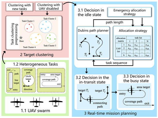
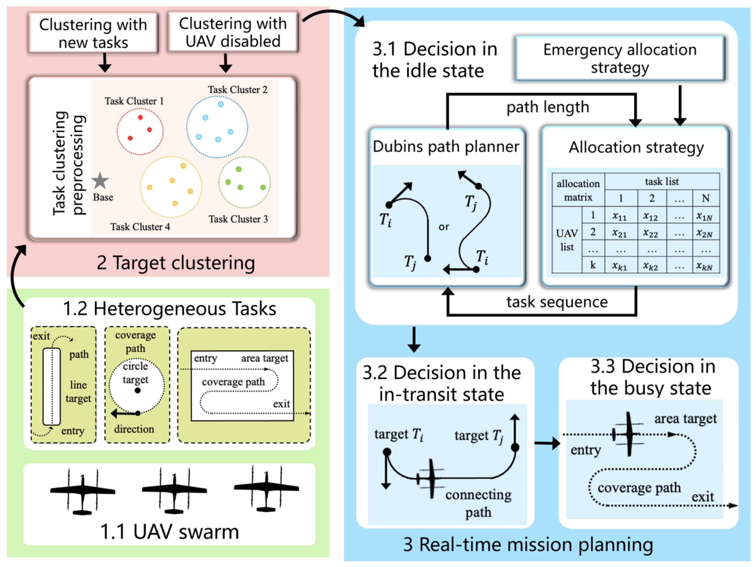
Aiming to address the above issues, this paper proposes a real-time collaborative mission planning method based on UAV states, as shown in Figure 1. UAVs have three main mission states: idle, in-transit and busy, as well as a possible disabled state, among which mission planning for idle state is the core. Mission planning for a UAV is performed in real time, and there is no pre-planned list of tasks or corresponding flight paths before departure. The UAV first preprocesses the tasks through the distance-based clustering method, then employs a Dubins planner to plan Dubins paths and obtains the length as the decision distance. Finally, it applies a low-complexity allocation policy to complete the task assignment in the idle state. When in the in-transit state, the UAV determines whether it has reached its target; when in the busy state, it checks whether the task has been completed. Disabled status indicates that the UAV has been physically damaged and is unable to fly. The contributions of this paper are summarized below:
Figure 1.
Overall structure of the proposed method.
- (1)
- Distinguishing it from previous decoupling methods, this paper proposes a coupled task assignment and path planning solution. Specifically, the distance cost in the task assignment phase is the Dubins path distance derived from path planning, while the final adopted path is determined by the result of task assignment. What is crucial here is that the Dubins paths employed for decision and flight are identical. This is equivalent to combining the two processes of task allocation and path planning into one, significantly reducing planning time. The adopted Dubins path allows the proposed method to take into account target heading angle constraints as early as the task assignment phase.
- (2)
- To enable real-time mission planning in both large- and small-scale scenarios, the following measures are implemented to accelerate the process. First, the speed of calculating the distance cost directly influences the efficiency of the task assignment. By reducing the types of Dubins path solutions and simplifying the solution format, the Dubins path generation time is s. Then, computationally lightweight task allocation strategies, such as greedy algorithms, are selected. The tedious iteration process is also rejected, retaining only low-level, computationally light iterations. Finally, the size of the decision space also directly influences the time for UAVs to make decisions. The preprocessing of clustering is employed to effectively partition the original large decision space into smaller subspaces to be allocated to each UAV, thereby accelerating the decision-making process.
- (3)
- To enhance the adaptability of the UAV, we extend the proposed method to address various emergency scenarios, including new tasks and UAV failures. Furthermore, we consider the extreme scenario where new tasks and UAV failures occur simultaneously, and we propose appropriate coping strategies.
The paper is organized as follows. Section 2 introduces the works related to mission planning. Section 3 not only describes the problem, but also introduces the heterogeneous tasks and the Dubins distance costs. The characterization and procedure of the proposed method are described in detail in Section 4. In Section 5, response strategies for new tasks and the disabling of UAV are discussed. Section 6 evaluates the effectiveness and performance of the proposed algorithm through simulation experiments. In Section 7, conclusions and directions for future work are summarized.
2. Related Works
Multi-UAV collaborative mission planning refers to assigning multiple tasks to multiple UAVs, simultaneously planning suitable paths to accomplish all tasks as quickly as possible. Mathematical models commonly applied to this problem include the multiple traveling salesman problem (MTSP) [6], the vehicle path problem [7], the mixed integer linear programming problem [8] and the weapon–target assignment model [9]. The MTSP is a classical model describing mission planning, which is characterized by high scalability and easy introduction of multiple constraints. Therefore, this paper also applies the MTSP to model the real-time mission planning problem.
Once the model is established, it can be solved by adopting appropriate optimization methods. Depending on whether the solution is optimal, the algorithms can be categorized as deterministic or heuristic. Deterministic algorithms include dynamic programming algorithms and Hungarian algorithms [10]. Heuristic methods include simulated annealing [11], greedy algorithms [12], auction algorithms [13], genetic algorithms [14], particle swarm optimization [15], and the artificial intelligence method [16]. Existing research usually decouples mission planning into two distinct components: task allocation and path planning. Task allocation precedes path planning, which finalizes the assignment of tasks and the traversal sequence for each UAV [17,18]. The outcomes of task allocation serve as the input for path planning. Path planning specifies the entry and exit angles of targets, and it smooths the path to satisfy non-holonomic motion constraints. The primary reason for the decoupling of mission planning in classical methods is that the applied distance cost is the Euclidean distance (straight distance) [19,20]. Straight paths are clearly not flyable paths under target heading angles and kinematic constraints. This makes path planning independent of and subsequent to task allocation. In fact, the two processes mutually impact each other. Although the decoupling process simplifies the problem, it also induces issues such as the inability to account for heading angles, low efficiency, and non-optimal solutions.
Many other studies have focused on task pre-assignment in static environments [21,22]. The UAV swarm performs initial global mission planning based on current environmental conditions, with a complete task list and corresponding paths before departure. Cho et al. [23] proposed an improved genetic algorithm for path planning of heterogeneous multiple Dubins vehicles performing remote tasks. Zhai et al. [15] used a hybrid particle swarm and entropy weighting method for cooperative task assignment of multiple heterogeneous vehicles. Yan et al. [14] proposed an improved genetic algorithm to solve the problem of integrated task assignment and path planning for multiple UAVs attacking multiple targets. Wang et al. [12] suggested a two-stage greedy auction-based algorithm to solve collaborative task allocation for large-scale UAV swarms. Although the above heuristic methods can obtain pre-assignment optimal solutions in static environments, they typically require multiple iterations and long computation times, making real-time planning unfeasible. Recently, Moon et al. [16] proposed an attention-based deep reinforcement learning method to solve the task allocation problem in manned–unmanned teams, but they only considered task allocation in static environments and ignored path planning. Additionally, most existing methods [12,14,21] focus on small-scale mission scenarios, but the time required for large-scale mission planning grows rapidly as the number of tasks increases. Therefore, it is crucial to propose a real-time planning method that can adapt to dynamic environments and large-scale scenarios. Compared to previous approaches, real-time planning must provide efficient and feasible scheduling results within limited time and computational resources, thus increasing the complexity and difficulty of the solution.
The scenarios encountered by UAVs in some of the studies are static, while assuming that the UAVs perform their tasks flawlessly and with excellence. This is not compatible with the real world, where the real environment is dynamic and variable. Therefore, Chen et al. [24] introduced a robust optimization method to address the parameter uncertainty problem. Additionally, to solve online problems involving time-sensitive uncertainty, they proposed a practical online hierarchical planning algorithm. Gao et al. [25] focused on the task reassignment problem in emergency situations and proposed a task reassignment algorithm based on contractual network protocols. However, this work did not consider the kinematic constraints of fixed-wing UAVs, meaning the generated paths are unflyable. Wu et al. [26] combined the attention mechanism with the improved self-organizing mapping algorithm to cope with emergencies such as new tasks and UAV failures. Cui et al. [27] proposed a three-layer framework for multi-UAV collaborative wildlife tracking. This framework employed a task allocation strategy combining pre-allocation with dynamic reallocation, prioritizing the tracking of targets with the highest position estimation uncertainty. Additionally, they investigated multi-target tracking and secure surveillance for heterogeneous multi-UAV systems operating in hostile dynamic environments [28].
In summary, the previous methods are hindered by three key issues: decoupled of task assignment and path planning, poor real-time performance and limited adaptability. Although each of the complex aspects mentioned above has been partially addressed in the literature, there has been limited work that systematically combines them all. Therefore, this paper explores a real-time collaborative mission planning method based on UAV states.
3. Preliminaries and Problem Formulation
Under the premise of ensuring the validity of the model, reasonable simplifying assumptions are made to reduce complexity. The fixed-wing UAV is modeled by a planar nonholonomic vehicle. The UAVs have collision-free paths by flying at different altitudes. The UAVs fly at a constant speed during the flight and have sufficient fuel to meet range constraints. In the mission scenarios discussed in this paper, obstacles and hazardous areas are currently not taken into account.
3.1. Problem Statement
Consider multiple UAVs forming a collaborative swarm flying in a 3D aerial environment and performing different operations against ground targets. Suppose a set of static targets with known locations is randomly distributed on the ground within the mission area. Specifically, denotes the base. A group of homogeneous UAV is centrally docked at the base station , awaiting their tasks, where the total number of and are N and K, respectively. It is also assumed that , which is commonly encountered in many practical applications. The purpose of mission planning is to assign tasks and plan paths in real time without a predefined list of tasks and corresponding paths, so that each task is visited by a UAV once and only once and the total distance is as small as possible. Finally, upon completion of all tasks, the mission sequence formed by the UAV swarm should satisfy the following equation:
Equation (2) indicates that the union of all UAVs’ task sets constitutes the complete task set, and the task sets of any two UAVs are mutually exclusive. is a decision variable that indicates whether the UAV travels from the target to the target .
Vehicles. The attributes of a UAV include configuration and status, represented by , where denotes the configuration of the UAV, including its horizontal position in Cartesian inertial coordinates and the heading angle , which increases in the counterclockwise direction. The Dubins model is introduced to establish the kinematics of the UAV and to generate the fundamental flight path. The Dubins path is the shortest path between two configurations and that satisfy curvature constraints, with a length expressed as . Additionally, represents the state of the UAV, and the four attributes of the UAV can be described by the following equation:
The idle status refers to the UAV not currently assigned to a specific target. The in-transit status indicates to the UAV flying along the path from the previous target to the next target . The busy status signifies that the UAV has arrived at the target and is performing the corresponding task. Additionally, the UAV may enter a special status known as disabled. As the name implies, this state typically indicates that the UAV has been physically damaged or has lost communication due to unforeseen circumstances, rendering it unable to fly.
Mission. Similarly, to better describe the properties of the task, it is represented by the . denotes the horizontal position of the task on the ground. represents the state of the task, which is illustrated in the following equation:
The unassigned status means that the task is not currently assigned to any UAV and has yet to be completed. Tasks in this state constitute the decision space for the UAVs and will be allocated to the appropriate UAV at the right time according to a specific policy. The assigned state indicates that the task has been assigned to a specific UAV, which may be either in-transit or actively performing the task. The completed status means that the UAV has planned an appropriate coverage path according to mission requirements and has completed the flight along that path. denotes the type of task, and different task types have varying connecting and coverage paths. See below for a detailed description.
3.2. Integer Programming Formula
The mission planning problem addressed in this paper can be modeled as an MTSP. Each feasible solution must satisfy a set of mission, vehicle, and environment constraints. The MTSP is transformed into an equivalent assignment-based double-exponential integer linear programming problem using the binary decision variables introduced above. The objective function is the total path length of each UAV’s movement. The path of that UAV comprises the following four parts: (1) the path from the base to the entry configuration of the first target; (2) all connected paths from the exit configuration of the current target to the entry configuration of the next target ; (3) the coverage paths of targets; and (4) the path from the exit configuration of the last target to the base station. The base is also a target. Obviously, the above four-part paths can be categorized into connecting paths and coverage paths. The connecting path refers to the feasible path for the UAV to move from the target to the target . After completing the previous task , the UAV naturally has a direction and may not be directed toward the next possible target . This means that the current position is subject to a heading angle limitation. Depending on whether an entry angle constraint exists for the next task , the connecting path can be further classified as either a CS-type or CSC-type Dubins path. The coverage path refers to the different shaped path planned by the UAV at the target based on the actual needs of the heterogeneous mission. The coverage paths are predefined and fixed. However, the connecting paths between task points exhibit significant variations depending on the task pair configuration. Thus, the length of the connecting paths can be optimized by different mission planning. The total length of the UAV path is calculated as follows:
where is the configuration of the UAV at the base; is the entry configuration of the target ; , is the exit configuration of the target , ; and is the length of the coverage path of the target . represents the Dubins path distance of the k-th UAV flying from the target to the target .
Thus, by utilizing the previously introduced UAV state variable , we transform the dynamic real-time planning problem into a sequence of static integer programming subproblems that evolve over time. The expression of its double–exponential integer linear programming is
Subject to
Constraints (12) ensure that exactly K UAVs leave and return to the starting point. Constraints (13) ensure that each mission point is visited once and only once. Constraint (14) is the Miller–Tucker–Zemlin (MTZ) constraint to eliminate subloops that do not contain the base, where represents the auxiliary continuous variable indicating the task execution order. Constraint (15) indicates the presence of a heading angle constraint at the mission point; takes a null value to indicate that there is no heading angle constraint, while takes a radian value to indicate the presence of a heading angle constraint. The state variable in constraint (16) represents the state of the UAV during real-time decision-making at time t. The integer programming model does not solve the global task allocation problem in one go but rather serves as a local decision-making tool for idle UAVs. The model is only invoked when assigning tasks to currently idle UAVs, at which point is a known parameter. Constraint (17) indicates that the curvature of the planned path must be less than or equal to the maximum curvature the UAV is capable of flying, where denotes the curvature of the Dubins path planned for the k-th UAV, and where represents the turning radius of the k-th UAV, whose reciprocal is the curvature. Constraint (18) ensures that the total number of tasks assigned to the k-th UAV is not excessively small.
3.3. Heterogeneous Tasks
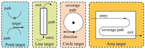
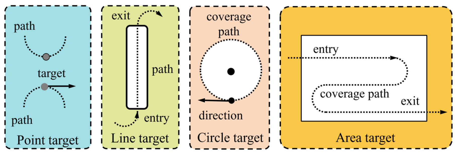
Much of the research on task allocation has focused on the characteristics of UAVs, while the characteristics of targets or tasks are often overlooked or regarded as homogeneous. However, in real environments there are various types of targets with different characteristics and shapes, such as buildings, motorways and squares. Therefore, in this paper, targets are categorized into four types: point target, line target, circle target and area target, based on their geometry characteristics, as shown in Figure 2. Point targets are further categorized into point target without direction constraints and point target with direction constraints based on whether they have a preset approach direction. Obviously, different types of targets have different connecting paths and coverage paths, as shown in Table 1. Depending on the mission, the shape of the coverage path varies, such as overflying the target point, straight-line traverses, circling, and Z-coverage. As shown in Figure 2, for a linear target the key parameters of straight-line coverage paths are length and direction. For a circular target, the key parameters of the coverage path are the radius and direction of the encircling path. The zigzag path for area targets consists of several simple semicircular turning paths and straight paths, with parameters including turning radius, straight path length, and flight direction.
Figure 2.
Different types of target. A target with an arrow indicates that the target has a heading angle constraint.
Table 1.
Characterization of connecting paths and coverage paths for heterogeneous tasks, where ‘1’ denotes CS-type path and ‘2’ denotes CSC-type path.
3.4. Dubins Path Distance Cost
Two types of two-point path planning problems arise in the above mission planning. One involves attitude constraints at both the UAV’s starting and termination points, with representative target types including constrained point targets. This path planning problem is identified as the classical Markov–Dubins problem, and its optimal solution is a CSC-type Dubins path, where C denotes a circular segment and S denotes a straight segment. Our previous work [29] proposed an efficient path construction method based on analytic geometry, which is not reiterated here.
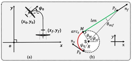
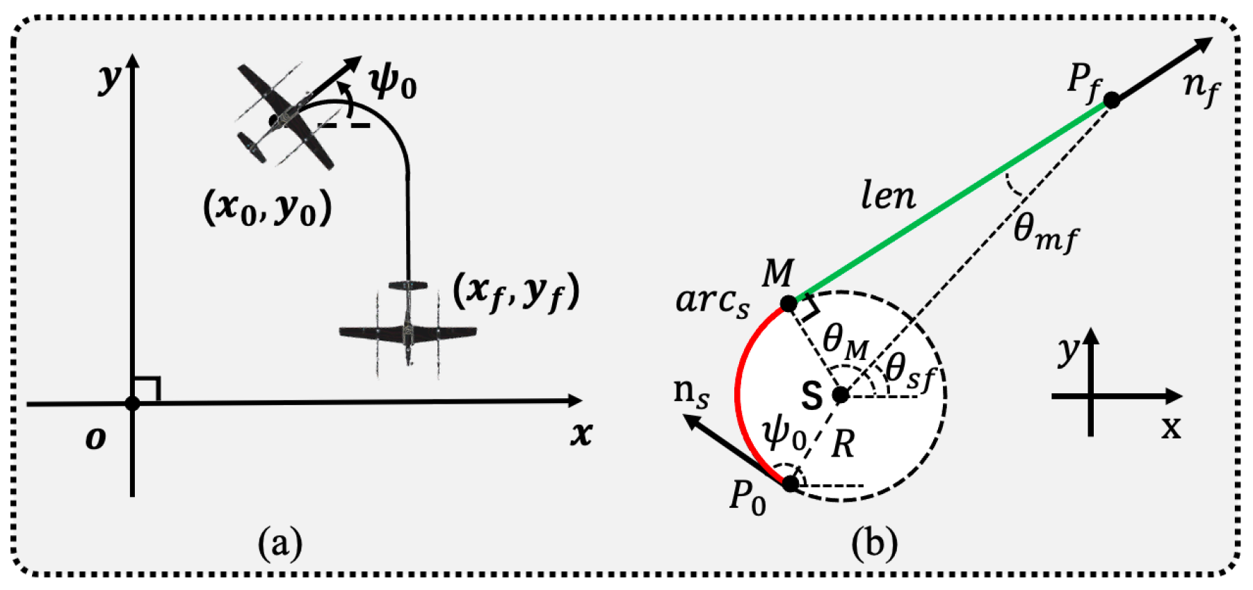
The other issue concerns a scenario in which only the starting point has attitude constraints, and the typical target type is an unconstrained point target, as illustrated in Figure 3a. On the one hand, the study [30] has demonstrated that the optimal path is a CS-type Dubins path with heading angle constraints at the starting point only; on the other hand, to further improve the computational efficiency, we adopt a more concise form of CS-type Dubins path. Compared to the four CSC-type (LSL, LSR, RSL, RSR) paths, the CS-type paths have only two types, LS and RS, as shown in Figure 3b, where R(L) stands for turning to the right (left) and S stands for straight flight. RS (LS) denotes that the path consists of rightward (leftward) arc and straight line.
Figure 3.
Dubins path: (a) Geometric of the degenerate Markov–Dubins problem. (b) CS-type path construction geometric intuition. The red arc denotes the starting arc; the green line denotes the intermediate tangent segment.
Considering the requirement for rapid construction of candidate optimal paths, this paper presents an analytic geometry-based method to generate CS-type Dubins paths. First, to obtain the path it is essential to utilize the steering of the initial arc to determine the center of the starting circle . This determines the position of the starting arc:
where is the starting point coordinate. When the UAV turns left, the angle is taken as , while if the UAV turns right then the angle is taken as ; is the heading angle of the starting point. R denotes the minimum turning radius.
Then, the coordinate of the tangent point M is derived. Based on the coordinates of the center of the starting circle and the endpoint, the angle between the connecting line and the X-axis can be obtained, as well as the length of the line segment :
where is the Euclidean norm of a vector, and is the target coordinate. The angle between line segment and tangent segment is gained by the following equation:
The position of the tangent point on the starting circle can be determined from the angle between the line segment and the X-axis, and can be obtained from the geometric relationship with the angle and the angle . When the path type is LS, the angle is calculated by the following equation:
When the path type is RS, the angle is obtained by the following equation:
Next, the starting arc is calculated. This involves determining the angles of the starting arc . The angle can be derived from its geometric relationship with the angle and the starting point attitude . When the path type is LS, the angle is calculated by the following equation:
When the path type is RS, the angle is gained by the following equation:
The length of the line segment, denoted as , can be determined using the coordinates of the tangent point M and the ending point :
Combining the two path planning problems, the path distance cost is given by the following equation:
denotes the length of the Dubins path of the k-th fixed-wing UAV flying from the start point to the end point .
4. Real-Time Collaborative Mission Planning Based on UAV States
4.1. Algorithm Overview and Procedure
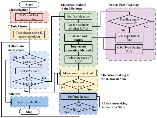
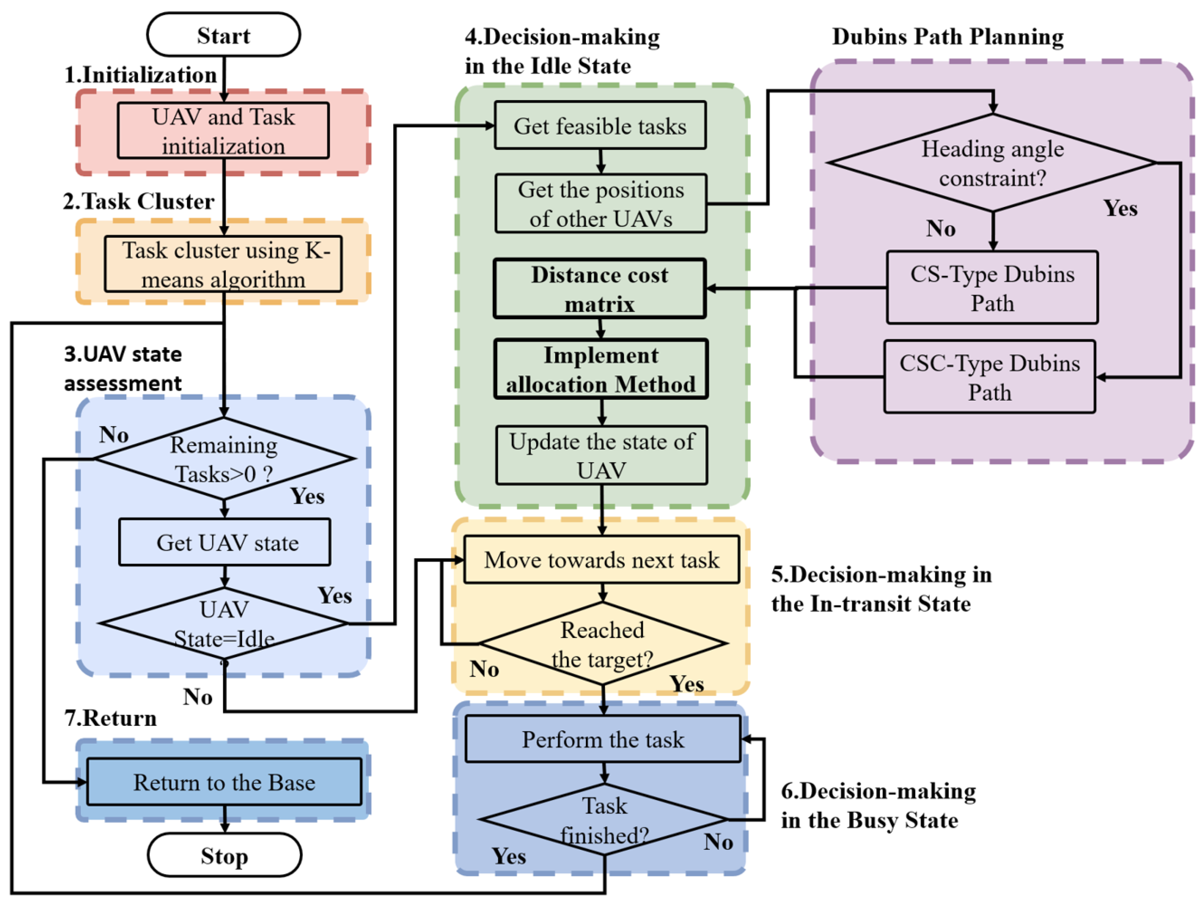
To achieve real-time planning that adapts to dynamic and uncertain environments, this paper proposes an algorithm for distributed mission planning. Decentralized decision-making significantly accelerates decision-making process while enhancing the system’s robustness. In the distributed approach, each UAV functions as an independent intelligent agent that ensures task space consistency by sharing and negotiating their respective resource and task demand information, ultimately leading to an overall reasonable task allocation scheme. The algorithm consists of seven important procedures or modules, as shown in Figure 4. The procedures are detailed as follows, and the pseudo-codes of the algorithm are shown in Algorithm 1. The next section will discuss new tasks and the disabling of UAVs.
Figure 4.
Framework for real-time collaborative mission planning based on UAV status.
Step 1. Initialization. Given the UAV’s prior parameters—such as the total number, configuration, and state, along with the range of motion and the total number of tasks—a random function is employed to generate the position of each task point, resulting in all tasks being initially unassigned.
Step 2. Task Clustering. The K-means algorithm is employed to classify all tasks into categories matching the total number of UAVs and to assign them to the corresponding UAVs based on appropriate rules. Since the K-means algorithm may converge to local minima, clustering requires an adequate number of iterations to obtain reasonable and stable results.
Step 3. Assessment of Task Completion and UAV State. The status of each tasks is assessed. Based on the completion status of all the tasks, it is determined whether the overall tasks of the UAV swarm are completed and the UAV swarm needs to return to the base. The state of each UAV serves as the basis for determining its next movement, and the three distinct UAV states exhibit different decision-making patterns.
Step 4. Decision-Making in the Idle State. The UAV first forms a list of unassigned tasks and obtains the configuration of the UAV. Then, the cost matrix is initialized and the distance cost is obtained using the Dubins path planner. Next, the appropriate assignment algorithm is invoked to obtain the assignment scheme. State changes are made based on whether the UAV is assigned to a task or not.
Step 5. Decision-Making in the In-transit State. Firstly, the distance between the UAV and the target at the current time is calculated, and the arrival criterion is used to determine whether the UAV has reached the task point. When the UAV reaches the task point, the status of the UAV should change to busy; conversely, the UAV should continue to fly the planned path.
Step 6. Decision-Making in the Busy State. Firstly, the UAV needs to plan the coverage path of the task in real time based on the type of task. Then the UAV executes the task and flies the coverage path. Finally, when the coverage path flight is completed, the UAV completes the task and its state becomes idle.
Step 7. UAV Return. Once all the tasks are completed, the UAV swarm can return. Each UAV utilizes the path planner to plan its path from the current position back to the base in real time and then begins flying.
| Algorithm 1 Multi-UAV real-time collaborative mission planning based on UAV status |
|
4.2. Key Modules and Their Functions
Task cluster. Before all the UAVs make their decisions, the algorithm starts with the clustering preprocessing. This module applies the K-means algorithm for multiple iterations to divide all tasks into clusters corresponding to the number of UAVs, and it then assigns each cluster to one UAV. This is a distinguishing feature of the algorithm. The purpose of clustering is twofold. First, task clustering allows different UAVs to be assigned to more centralized task clusters. The paths between the UAVs are almost non-intersecting or slightly overlapping. Thus, the total distance traveled by all the UAVs is reduced, and the task allocation tends to be as optimal as possible. Then, the size of the decision space directly impacts the duration of the UAV decision-making process. Clustering preprocessing can effectively partition the original large decision space into smaller subsets allocated to each UAV, thus reducing the decision time.
Dubins path planning. Distance cost is an important basis for UAV decision making in the idle state. Another strength of the algorithm is that it employs the Dubins path distance as a cost function. The construction of the Dubins path is described in detail earlier, and it offers three key benefits. Firstly, the Dubins path length accurately characterizes the actual kinematic distance between the two task points. Decisions based on this distance cost may differ from those applying straight-line distances, leading to variations in the mission planning scheme. Secondly, the proposed Dubins path generation method quickly obtains the paths and computes the distance cost to meet the time constraints. Finally, regardless of whether the target has heading angle constraints, the connecting path between the two targets can use the Dubins path. This, in turn, makes it possible to fully take into account the heading angle constraints during the task assignment phase. Further, this allows our algorithm to handle heterogeneous tasks.
Allocation strategy. Allocation strategy refers to the task allocation method used by a UAV in an idle state. The modularity of the allocation strategy allows the use of multiple allocation methods. However, the goal of the algorithm is not to achieve the optimal allocation in a computationally light iteration, but rather to obtain a near-optimal or acceptable allocation. This is a trade-off between optimality and real-time. Therefore, we focus on an allocation strategy with low computational effort. The greedy algorithm is adopted due to its high efficiency even under large-scale conditions. This is another advantage of the proposed method, which rejects the tedious iterative process and retains essential low-level iterations with minimal computational overhead.
To evaluate the real-time performance and scalability of the proposed method, its computational complexity is analyzed. The method first performs clustering preprocessing on the tasks using K-means, dividing N tasks into K clusters equal to the number of UAVs. Its time complexity is , where is the number of iterations. Since is a constant, the clustering complexity simplifies to . During the task assignment phase, the method calculates the Dubins path length from the UAV’s current configuration to the candidate tasks. Depending on whether the task imposes a heading angle constraint, either the CS-type or CSC-type Dubins path is employed. Regardless of the type, each path is computed using closed-form analytical geometry formulas. Hence, the time complexity for a single Dubins distance calculation is , with its constant upper bound denoted as . After clustering, each UAV is assigned to a task cluster, with an estimated number of tasks equal to . The idle UAV computes the Dubins distance to all unassigned tasks within its cluster and selects tasks using the greedy algorithm. Assume the task cluster of UAV contains tasks, . The UAV performs task assignments. During the j-th assignment, it needs to compute distances to the remaining tasks. Thus, the total computational cost of UAV is
The total computational cost of all UAVs is
Neglecting the low-order terms , the complexity of the task allocation is . Therefore, the total time complexity of the proposed method is .
5. Emergency Situation
UAVs and their external environments are subject to frequent changes, so UAVs must possess real-time planning capabilities to provide effective solutions during emergencies. Real-time mission planning and replanning during emergencies further emphasize the time constraints on methods, necessitating that they complete mission planning within limited computational resources and time.
5.1. Strategy for New Tasks
The most common emergent scenario for UAVs during the flight is the emergence of new tasks. The emergence of new tasks implies real-time planning, including task clustering and real-time task allocation. Therefore, the challenges of addressing this emergent situation are twofold. The proposed method is a real-time planning approach that does not rely on a predetermined task sequence. Hence, it is inherently capable of addressing the real-time planning. Additionally, the emergence of new tasks necessitates preprocessing for clustering. This tricky problem is the focus of our solution efforts.
An indeterminate number of new tasks can emerge at any time during the flight. Let denote the set of new tasks that need to be assigned, , where denotes the i-th new task to be assigned. And the new tasks are non-urgent and can be completed by UAVs without time constraints during the mission. To process new tasks, the UAV formation must first gather relevant information about the new tasks, including its location and type, and then share information within the formation. The new tasks still require preprocessing through clustering, but in a different way than the initial static tasks. Since the clustering of the initial tasks has established an acceptable criterion, the criterion for the new tasks should align with it. Due to the initial task clustering generating K cluster centers , the allocation of new tasks can be determined based on their distance from each cluster center:
where represents the position of the i-th new task. Then, based on the distance , the new task will be assigned to the UAV corresponding to the nearest cluster:
After a new task is assigned to a UAV, two possible situations arise regarding its execution. In the first case, the UAV has not fully completed the initial tasks, and some tasks remain. Thus, new tasks may alter the original task execution sequence, including the order and connecting paths of the tasks. In the second scenario, the UAV has completely accomplished the initial tasks. When new tasks appear, the UAV immediately proceeds to the new tasks without altering the original task execution sequence.
5.2. Strategy for Disabled UAV
Due to mechanical failures and communication breakdowns, the UAVs are not functioning properly and, naturally, can no longer carry out their tasks. Then the UAVs are deemed to be in a disabled state. Obviously, disabled UAVs reduce the number of available UAVs in the UAV swarm and also alter the original mission planning scheme. This indicates that UAV swarms should undergo mission re-planning.
Let denote the set of available UAVs after excluding the disabled ones. Suppose there are disabled UAVs, denoted by , where each , is the initial set of UAVs. Then the available UAV set is . The disabling of a UAV does not affect mission planning when all tasks assigned to that disabled UAV are completed; it simply means fewer UAVs are available. However, when a UAV has been disabled when it has not yet completed all its assigned tasks then that can significantly impact the UAV’s mission planning. A disabled UAV cannot continue completing tasks and immediately release the tasks, changing its status to unassigned. Based on the distance to the clustering center of other available UAVs, and following the principle of proximity, all uncompleted tasks originally assigned to the disabled UAV will be reassigned to available UAVs. For the UAV receiving tasks, if it is idle and has no other candidate tasks then it will immediately use the allocation strategy to select the task and plan the path from its current location to the task. If it is en route or busy, it will first complete its assigned task then select the task based on the assignment strategy and plan the path. Since the task is non-urgent, it will not be immediately taken on by an available UAV.
5.3. Emergencies Occurring Simultaneously
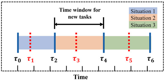
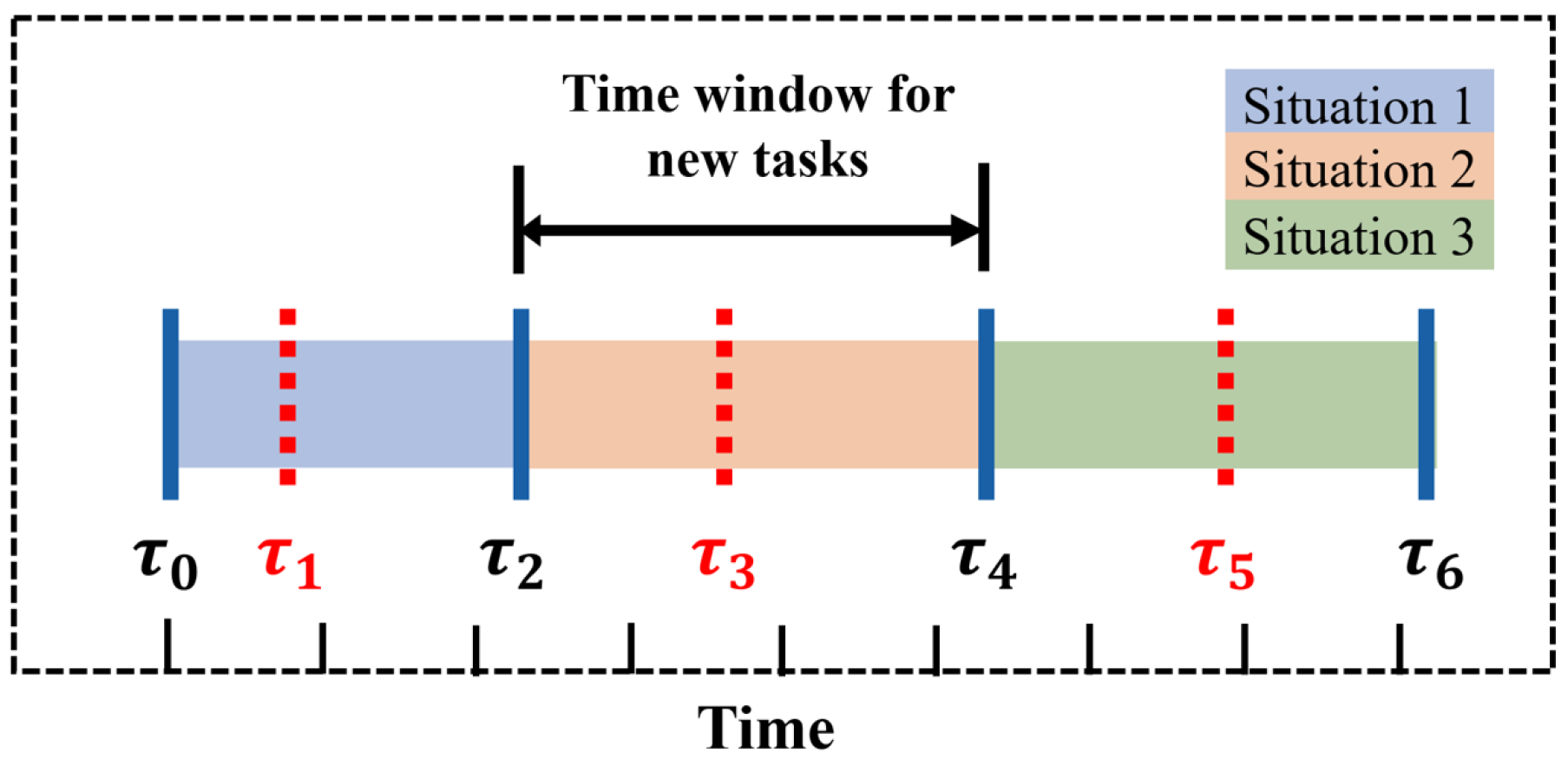
Extreme scenarios where new tasks appear and a UAV is disabled simultaneously are complicated. To analyze the various scenarios in a comprehensive and clear manner, we divide them into three categories based on the sequential relationship between the time when the UAV is disabled and the emergence of new tasks (as shown in Figure 5):
Figure 5.
The sequential relationship between the disabled time of UAVs and the emergence of new tasks is as follows: and represent the start and end times of the UAV swarm mission, respectively. The time interval indicates the window during which new tasks may arise, while , , and correspond to the times at which the UAVs are disabled in each of the three scenarios.
- (1)
- The UAV is disabled before new tasks appear, . The entire process of mission planning in this scenario involves two phases. First, the mission planning under the UAV that will be disabled takes place. After the UAV is disabled, the new tasks emerge. Then, the scenario can be considered a new mission planned under conditions with a reduced number of available UAVs when new tasks arise.
- (2)
- The UAV is disabled after new tasks appear, . The complete mission planning process in this scenario consists of two phases. First, the UAV swarm conducts mission planning with only new tasks emerging. Subsequently, the new task ceases to appear, and the UAV is disabled. This is equivalent to mission planning with an increase in total mission tasks when the UAV is disabled.
- (3)
- The UAV is disabled during the emergence of new tasks, . The complete mission planning process in this scenario consists of three distinct phases. First, the UAV swarm conducts mission planning with only new tasks appearing. Suddenly, the UAV is disabled and, under these conditions, the swarm begins equivalent mission planning with an increase in tasks. Subsequently, new tasks continue to emerge. The swarm engages in mission planning for the emergence of new tasks with a reduced number of available UAVs.
In summary, although there may be many possible situations when two emergency situations occur simultaneously, identifying a pattern becomes straightforward upon careful analysis. The emergence of new tasks only increases the total number of tasks, which does not significantly impact the re-planning process when a UAV is disabled. On the contrary, the disabling of the UAV leads to a reduction in available UAVs, directly impacting the preprocessing of clustering for new tasks. Therefore, when two emergencies occur simultaneously, only the part of the clustering processing of the new tasks needs to be adjusted to accommodate the full scenario. The adjustment involves determining whether the corresponding UAV is available before calculating the distance between the new task and the clustering center.
6. Simulation Result and Analysis
This section first introduces the simulation environment settings, then uses a series of simulations to evaluate the performance of the proposed method, and, finally, verifies the robustness and adaptability of the method through three emergency scenarios.
6.1. Simulation Environment Settings
These algorithms were deployed and tested in MATLAB R2022a on a standard PC running Windows 10, equipped with an Intel Core i7 2.2 GHz CPU and 8 GB of RAM.
The UAVs are fixed-wing UAV with a large aspect ratio and long endurance. It is assumed that all the UAVs fly at a constant speed throughout the mission, with the speed set to m/s. The minimum turning radius of the UAVs is 80 m. The UAVs depart from the base S simultaneously to reach their respective targets, complete the missions, and then return to the base after finishing the tasks. It should be noted that all the UAVs return to the base station together only when all the tasks are completed. This implies that some UAVs may enter a hovering or waiting state at the final stage of the flight.
To validate the effectiveness of the proposed algorithmic framework, it is compared with the simulated annealing (SA) algorithm, the greedy-based task assignment approach with Euclidean distance (GBA), the Hungarian-based approach with Euclidean distance (HBA), and the auction-based approach with Euclidean distance (AA), where SA is used as a benchmark with an initial temperature of 50° and a hyperparameter value of 0.99 for exponential cooling. Each Markov chain is run 500 times and the algorithm is terminated when the temperature drops below 10° or the total number of iterations reach 1000. The above four methods are used for task pre-allocation in a static environment. Before departure, the UAVs perform initial task allocation with detailed task lists and corresponding paths. Note that the straight paths obtained cannot be flown directly and need to be smoothed using Dubins paths. Thus, the above four methods are unable to process new tasks and UAV damage situations in real time. Based on our framework, the mission planning methods are proposed: the preprocessing-enabled real-time mission planning approach based on Dubins path distance (PRBDD) and its variant without preprocessing (RBDD). When employing a greedy task assignment strategy, they are referred to as PRBDDG and RBDDG, respectively.
6.2. Allocation Based on Different Distance Costs
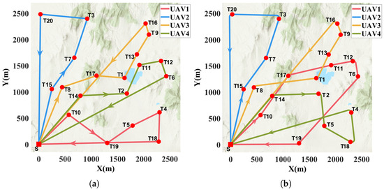
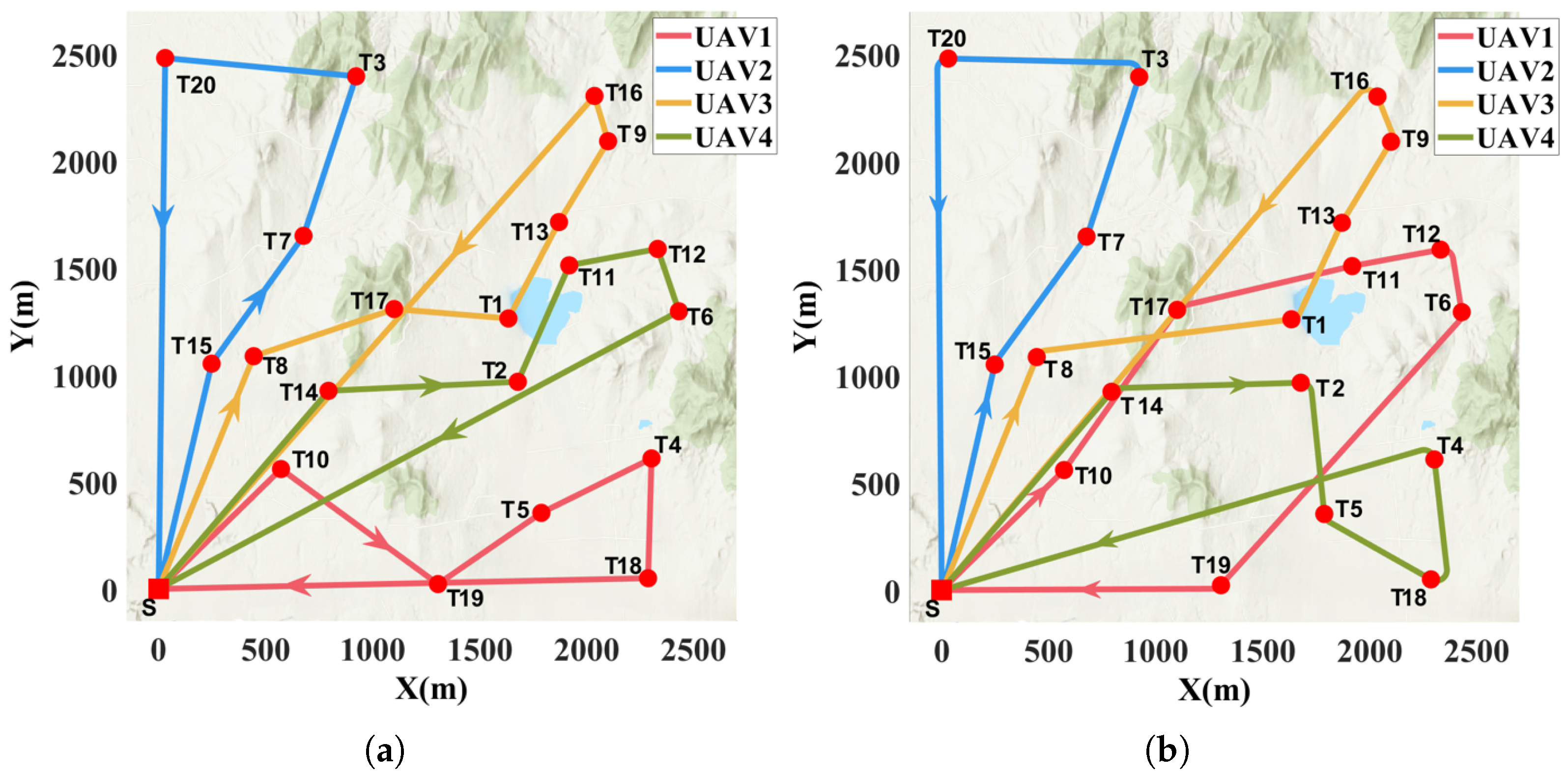
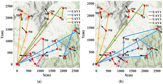
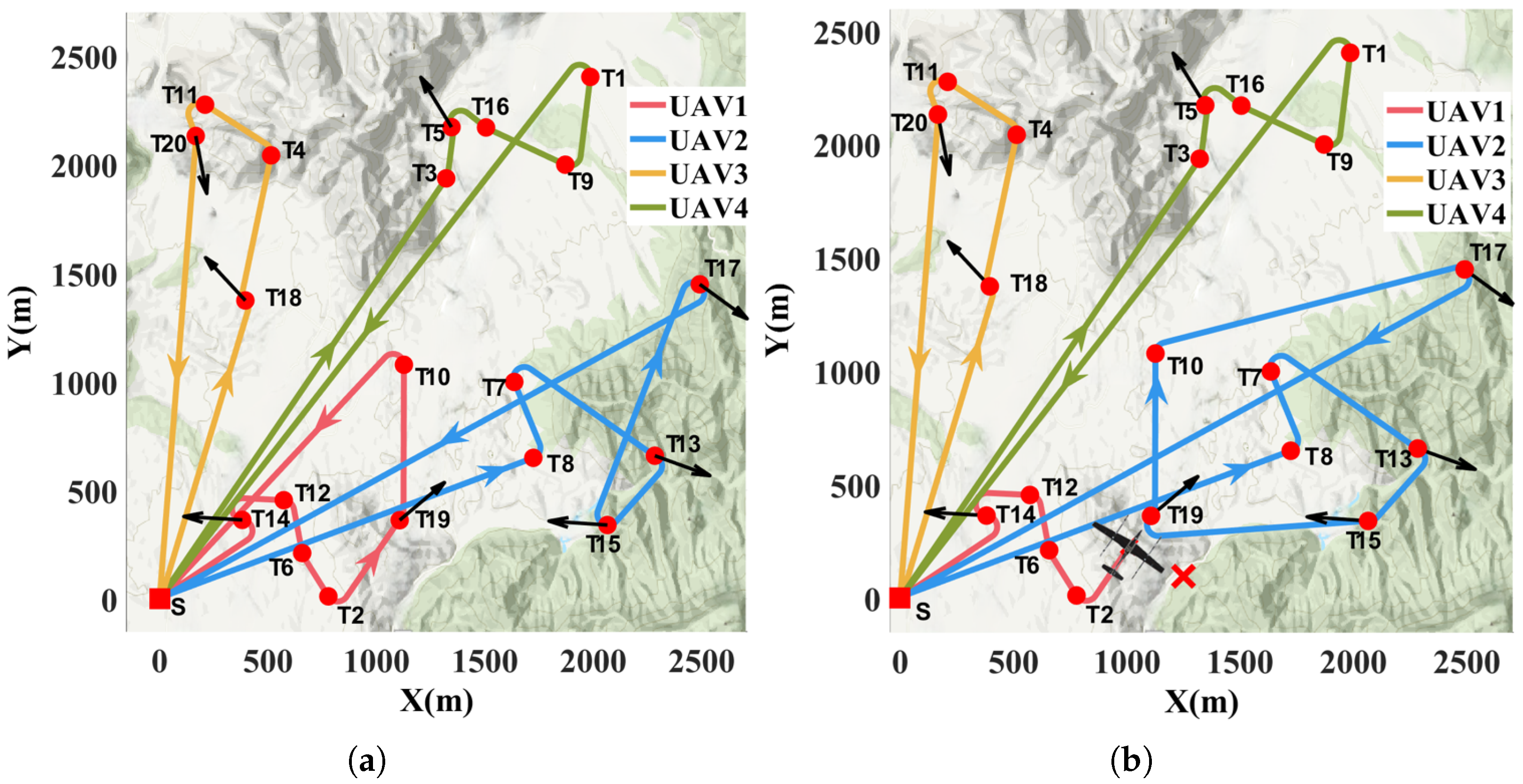
Differences in the distance cost employed for task assignment may lead to significantly different assignment results. This claim is validated in the following mission scenario. The scenario involves four homogeneous UAVs completing 20 randomly generated tasks within 2.5 km × 2.5 km area. Since the Euclidean distance cost cannot take into account the heading angle constraints, the task is limited to a point task without a heading angle constraint, which can be completed by any UAV. The locations of the tasks are randomly generated, and their distribution within the task area is shown in Figure 6. The red square indicates the base station and the red dot represents the task locations. The methods applied in this scenario are GBA and RBDDG.
Figure 6.
Final mission planning results based on different distance costs: (a) Mission planning based on Euclidean distance. (b) Mission planning based on Dubins path distance.
As can be seen from Figure 6a, the GBA only completes the task assignment process, while path planning is not performed. The resulting path is a straight line, ignoring the heading angle, which prevents the UAV from following the path directly. In contrast, our method RBDDG is continuous and smooth, aligning with the UAV’s kinematic constraints, as in Figure 6b. In addition, the two planning methods exhibit entirely different allocation schemes. Except for UAV 2, which has the same assignment, the other three UAVs not only have different tasks in the different mission schemes, but also the order in which the tasks are performed is different, as shown in Table 2. Due to the differences in both the tasks and their execution order, the distances flown by the UAVs also varies across the different methods. Comparative experiment demonstrates that the difference in distance cost has an impact on the task assignment results.
Table 2.
Mission planning details based on different distance costs. The red numbers indicate different task assignments for UAVs.
To further illustrate how different distance costs affect mission planning, we take a closer look at Figure 6a,b. The key to all subsequent task assignments is that UAV 1 chooses task 17 instead of task 19. To better understand the logic behind decision-making, the Dubins path distance is divided into two components: the straight-line distance between the previous and next task points, and the additional distance due to heading angle correction. As task 19 is closer to task 10 in a straight distance, the UAV using the GBA method selects task 19 as its next task. In contrast, when using the Dubins path, the additional heading correction distance for task 19 is significantly longer than for Task 17, which increases the total path length. Thus, the UAV using RBDDG chooses task 17. This is the mechanism by which the additional distance due to heading angle correction affects task assignment. The key prerequisites for its effectiveness are that the two tasks are at similar straight-line distances from the current position and that their heading angles differ.
6.3. Comparison and Evaluation of Proposed Algorithms
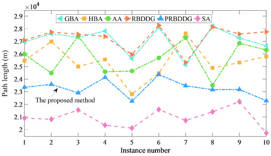
To fully characterize the proposed algorithms, this section compares the six algorithms in both spatial and temporal dimensions. The experimental scenario in this section is the same as that in the previous section. The simulation was conducted 50 times, with 25 tasks randomly generated each time without repetition. Figure 7 shows the total distance traveled by four UAVs applying six methods in 10 out of 50 simulation results. Obviously, SA obtains the optimal allocation scheme, resulting in the shortest distance traveled by the UAV. As shown in the figure, all four methods, RBDDG, GBA, HBA and AA, provide only feasible allocation schemes, with their total UAV travel distance being significantly longer than the optimal solution, which is close to each other. On the contrary, the solution obtained by PRBDDG is superior to other comparative methods and even close to the optimal solution. The gap refers to the difference between the total distance traveled by the UAVs in the other methods and that obtained by the SA, with a smaller gap indicating a method that is closer to the optimal solution. The average gap for PRBDDG is , while the average gaps for the other four methods are all above .
Figure 7.
Spatial comparison results of six different methods: the total distance.
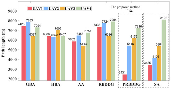
Figure 8 displays the distance traveled by each of the four UAVs employing the six different methods in the fourth example. The distances traveled by each UAV for PRBDDG are similar to those for the SA, with some UAVs traveling farther and others traveling shorter distances. In contrast, the flight distance of each UAV in the other four methods is more balanced. The reason for this phenomenon is the clustering of tasks. The PRBDDG effectively avoids task assignment averaging by applying clustering preprocessing to assign tasks differentially to UAVs. To further illustrate that the optimal solution involves differentially assigning tasks, we also calculated the difference between the longest and shortest distances traveled by the four UAVs, as well as the difference in the number of missions assigned to the UAVs. As shown in Table 3, the difference in distance traveled and the difference in the number of tasks for the SA are the largest among the six methods, followed by PRBDDG, with the small differences seen in the other four methods. This indicates that the optimal solution involves differentially assigning tasks, rather than distributing tasks equally among UAVs. Differential allocation can effectively avoid crossing or overlapping paths, thereby shortening the total path. This is the mechanism that allows PRBDDG to achieve near-optimal solutions.
Figure 8.
Spatial comparison results of six different methods: distance traveled by each UAV in the fourth example. The SA method marked by the dashed line is the optimal solution. The other dashed line marks our proposed method.
Table 3.
Spatial correlation quantities of six different methods. The variance is in parentheses.
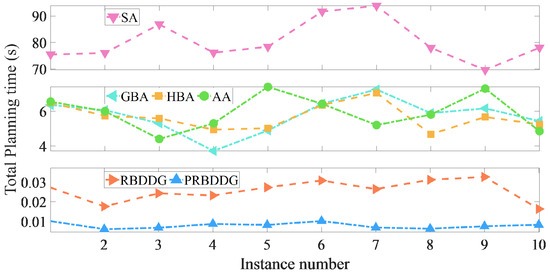
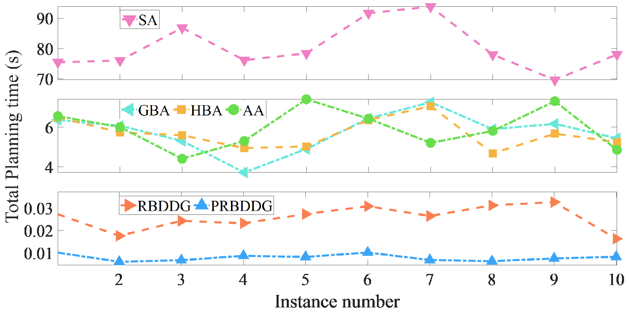
The comparison of the methods in terms of time is shown in Figure 9 and Figure 10. Figure 9 displays the total mission planning time by four UAVs applying six methods in 10 out of 50 simulation results. Obviously, PRBDDG has the shortest total mission planning time, RBDDG requires more time. This suggests that clustering preprocessing further reduces the time required for mission planning. The total mission planning time for GBA, HBA, and AA is in the range of a few seconds, while the total time for the SA approach is measured in minutes.
Figure 9.
Time comparison results of six different methods: total time for mission planning.
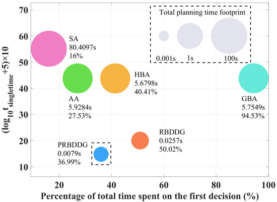
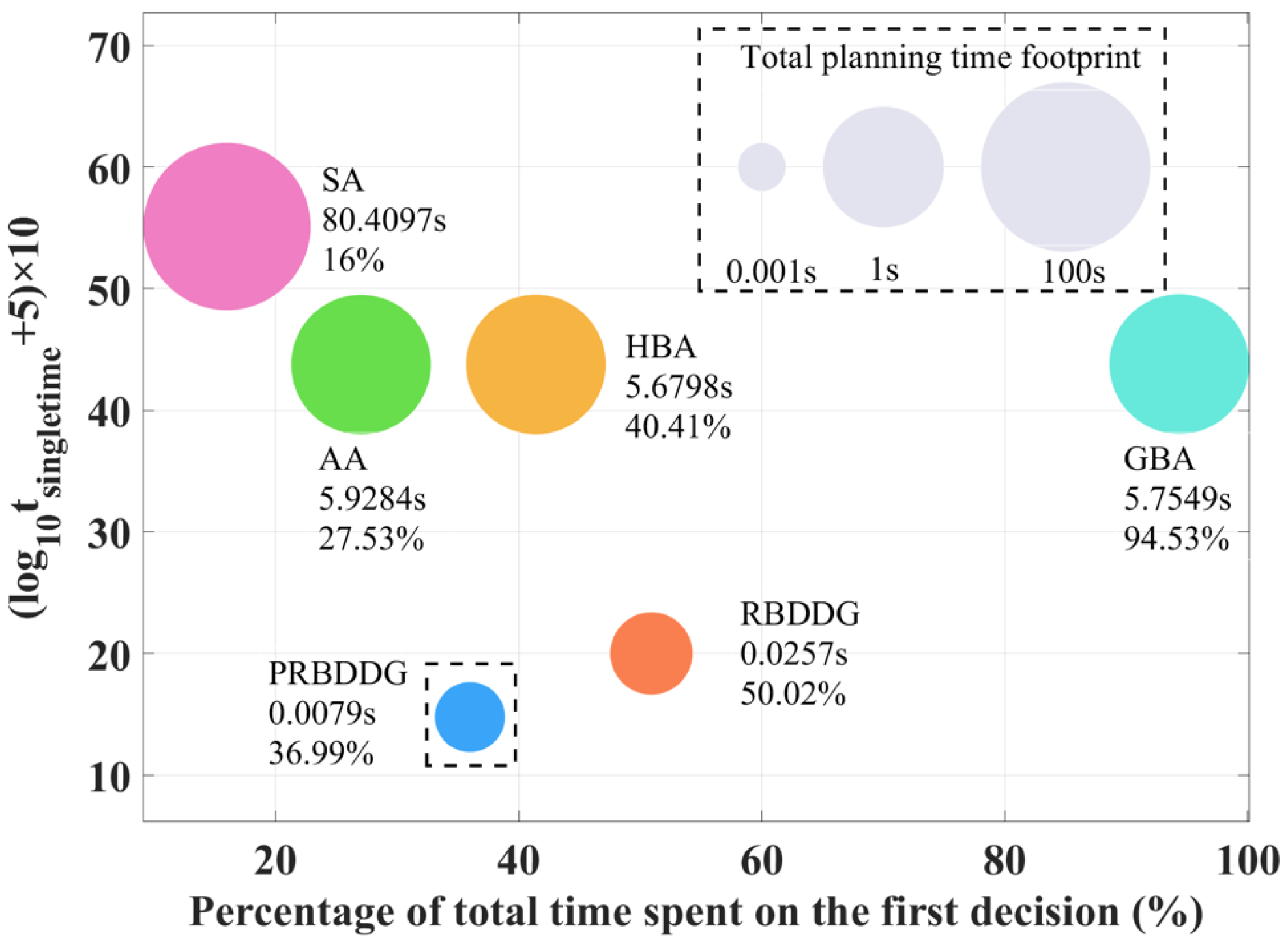
Figure 10.
Time comparison results of six different methods. The dashed line marks our proposed method.
Figure 10 exhibits the performance of the six methods in terms of average total planning time, average single planning time, and time spent on the first decision as a percentage of the total time. Note that the total time includes the time for task allocation and path planning. The average single planning time is equal to the average total time divided by the total number of tasks. The size of the circles in different colors indicates the average total planning time required; the larger the circle, the longer the time needed. It can be seen that PRBDDG requires the shortest average total planning time, followed by RBDDG, with SA requiring the longest time. The average planning time for different methods varies by orders of magnitude, so showing all methods on the same graph requires mathematical manipulation. The approach is to take logarithms before scaling. The vertical axis of Figure 10 then represents the average single planning time, with larger values implying longer times. The results of the comparison of the average single time for the six methods are consistent with the comparison of the total time. The results also suggests clustering preprocessing is also effective in reducing the single mission planning time by decreasing the size of the decision space. It is worth noting that the single planning times for PRBDDG are in the order of , as shown in Table 4. The horizontal axis of Figure 10 represents the proportion of the total time taken by the UAV to complete the first mission planning while hovering at the starting point. A higher percentage in this ratio indicates a shorter mission planning time during flight. The GBA has the highest time percentage, while PRBDDG has a small percentage.
Table 4.
Time related quantities of six different methods. The variance is in parentheses.
Based on the quantitative comparisons above, Table 5 summarizes the key features of each algorithm, providing a more intuitive reflection of the strengths and weaknesses of each algorithm.
Table 5.
Key performances comparison of each mission planning method: Coupled solution (CS), Real time (RT) performance, Emergency (EM), Quality (Qu); ✔ indicates that the method performs well in terms of performance, while ✘ indicates that the method performs poorly in terms of performance improvement; ‘*’ indicates that this is the proposed method.
6.4. Heterogeneous Task Scenarios
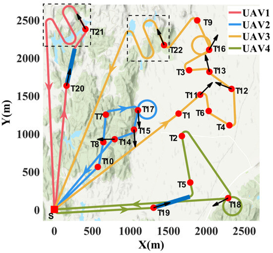
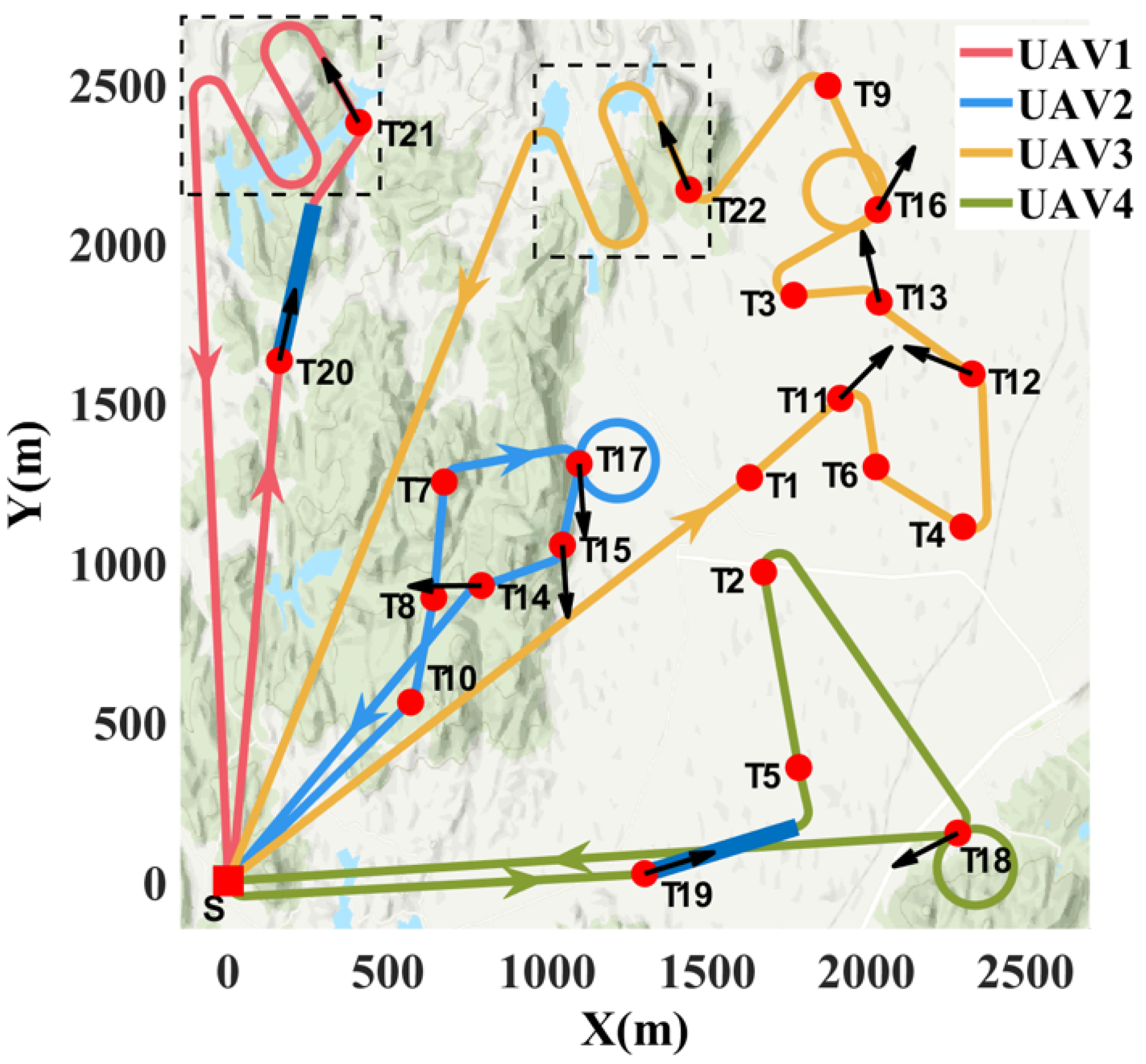
Figure 11 provides a comprehensive illustration of a typical application of the proposed algorithm. After all the tasks are completed, the task sequences of UAVs 1, 2, 3, and 4 are 20-21, 10-8-7-17-15-14, 1-11-6-4-12-13-3-16-9-22, and 19-5-2-18, respectively. First, it is apparent from the figure that the tasks performed by the four UAVs are clearly grouped into clusters. Different UAVs execute distinct task clusters. The preprocessing of task clustering introduces differentiation in task allocation, leading to significant variations in the number of tasks performed and the distance traveled by the UAVs. Figure 11 illustrates the ability of the UAVs to perform five heterogeneous tasks. Tasks 16–18 are circular tasks, tasks 19 and 20 are linear tasks, and tasks 21 and 22 are area-based tasks. These heterogeneous tasks are effectively performed by different UAVs. This is attributed to the adopted CS-type and CSC-type Dubins paths. Both path types fully consider task outgoing angle constraints, ensuring that the UAV’s path adheres to kinematic constraints without abrupt changes in direction. CSC-type paths also account for tasks with incoming angle constraints, such as straight-line targets, area targets, and others. This allows the UAV to smoothly comply with the heading angle constraints upon reaching the target position, enabling it to immediately begin executing the mission without the need for transition paths. Notably, linear and area missions cause significant changes in the UAV’s position, moving it away from the original mission location. This poses a considerable challenge for static planning. However, our proposed algorithm shows strong real-time performance. As a result, it employs the current UAV position and attitude to determine the next task and plan the path in real time.
Figure 11.
Schematic diagram of the final result for a typical application scenario of the proposed method.
6.5. Scalable
To further validate the effectiveness of the proposed method in large-scale examples, several sets of experiments were conducted at different scales using the algorithm. In the scalability experiment, 4–1000 UAVs completed randomly generated 25–25,000 targets in a 2.5 km × 2.5 km area, and each set of experiments was repeated 50 times. The average single planning time with variance at each scale is recorded in Table 6. As can be seen from the table, the more tasks there are, the more the time for single planning increases subsequently; whereas, the increase in the number of UAVs means that each UAV is assigned to fewer clustering tasks, which effectively reduces the planning time. In an extreme case where a large number of UAVs form a cluster to complete large-scale tasks, the method can still effectively carry out rapid mission planning. The planned paths are not optimal in large-scale scenarios. However, the planning time is more concerned than the path length; therefore, non-optimality is acceptable. Our experiments at different scales show that the method performs quickly and consistently in both small- and large-scale scenarios.
Table 6.
Different scales’ average single planning time and variance. The variance is in parentheses. The slash indicates that the simulations are not conducted because the number of UAVs exceeded the number of tasks or the number of tasks assigned to the UAVs is too low.
6.6. New Task
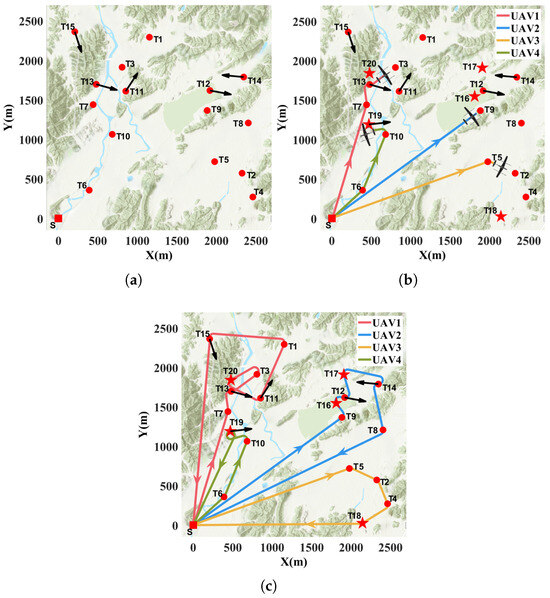
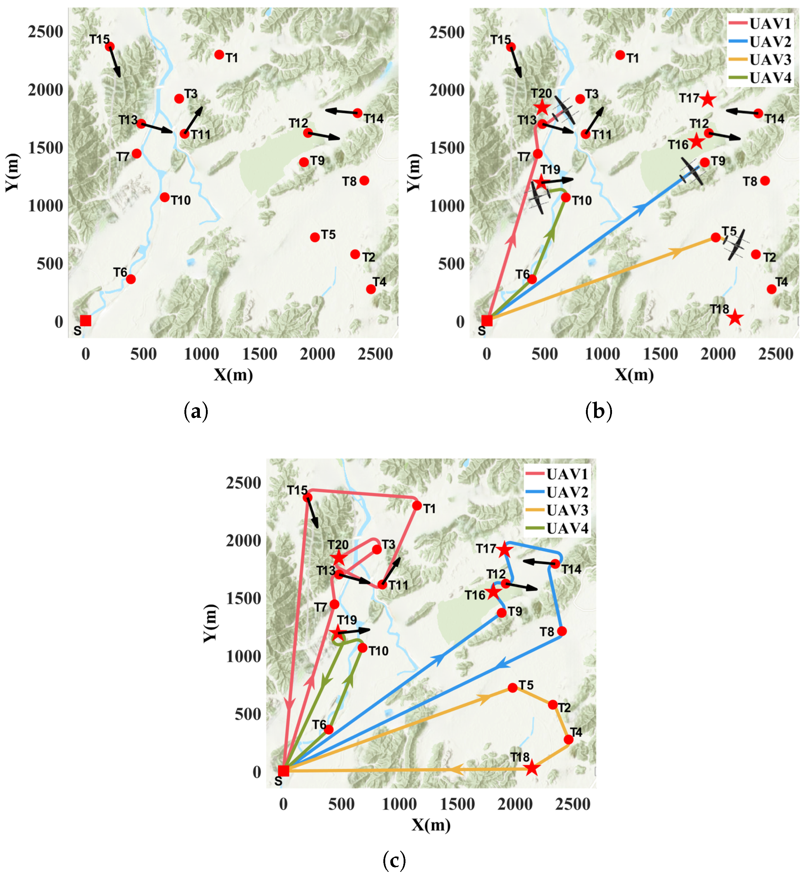
This section verifies that the proposed method can be applied to scenarios with new tasks. The base scenario in this section is the same as that in the previous section. The scenario involves four UAVs to accomplish 15 randomly generated tasks in a 2.5 km × 2.5 km area. The scenario consists of 10 unconstrained point targets and 5 constrained point targets, which can be accomplished by any of the UAVs, as shown in Figure 12a. The circle, line and area tasks are similar to the constrained point targets. Therefore, these tasks apply point targets with heading angle constraints instead to simplify the problem. Similarly, the new tasks are restricted to the unconstrained point targets and constrained point targets. It is assumed that none of the new tasks are urgent. Figure 12 displays the UAV swarm performing the mission at different moments in a scenario where new tasks emerge. There are five new emerged tasks, four of which are unconstrained point tasks and one constrained point target. The new tasks are assigned to the corresponding UAVs based on the clustering criterion when they appear. UAVs 1, 3, and 4 execute new task 20, 18, and 19 respectively; UAV 2 executes new tasks 16 and 17. Figure 13 quantitatively presents the key time points for each new task: appearance time, assignment time, and completion time, and labels the UAVs that perform the task. The final mission sequences for UAVs 1, 2, 3, and 4 are respectively: 7-13-3-20-11-1-15, 9-16-12-17-14-8, 5-2-4-18, 6-10-19. From the time plot, it can be seen that the allocation of non-urgent new tasks is closely related to both the time and the location of the task occurrence.
Figure 12.
Completion of tasks by UAV swarm at different times as new tasks emerge: (a) t = 0 s; (b) t = 47.39 s; (c) t = 167.25 s. Red pentagrams indicate emerging tasks.
Figure 13.
New task appearance, allocation, and completion time chart. Task appearance, allocation and completion are represented by circles, triangles and rectangles respectively. Red, blue, yellow and green indicate that the tasks are performed by UAVs 1, 2, 3 and 4 respectively.
6.7. Disabled UAV
This section verifies that the proposed method can be applied to scenarios where a UAV is disabled. This scenario involves four identical UAVs completing 20 randomly generated tasks within a 2.5 km × 2.5 km area. The tasks consist of 12 unconstrained point targets and 8 constrained point targets, all of which can be completed by any of the UAVs. Figure 14a illustrates the planning diagram of the tasks without UAVs being disabled. From the figure, we can see the task distribution and the respective order of completion for each UAV distance. At the 50th second, UAV 1 is disabled at coordinates (1079.91, 326.88). Figure 14b displays the mission planning diagram with UAVs disabled. After UAV 1 is disabled, its remaining unfinished tasks (19,10) are reassigned to UAV 2 and inserted into the original task sequence, disrupting the order of task execution. UAV 1 actually completes four tasks. And UAV 2 actually completes seven tasks. UAV 4 completes five original tasks. UAV 3 completes four original tasks, of which two (tasks 18 and 20) are constrained tasks. The specific task sequence of each UAV is shown in Table 7. The reassignment of the remaining tasks is closely related to both the disabling time and the locations of the tasks.
Figure 14.
Mission planning final results in the scenario where UAV is disabled: (a) Planning diagram of missions without UAVs being disabled. (b) Planning diagram of missions with UAVs disabled. The red cross next to the UAV indicates that the UAV is disabled.
Table 7.
Comparison of tasking by UAV with and without UAVs being disabled. The red numbers indicate different task assignments for UAVs.
6.8. Extreme Scenario Simulation
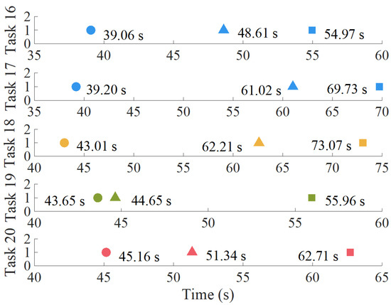
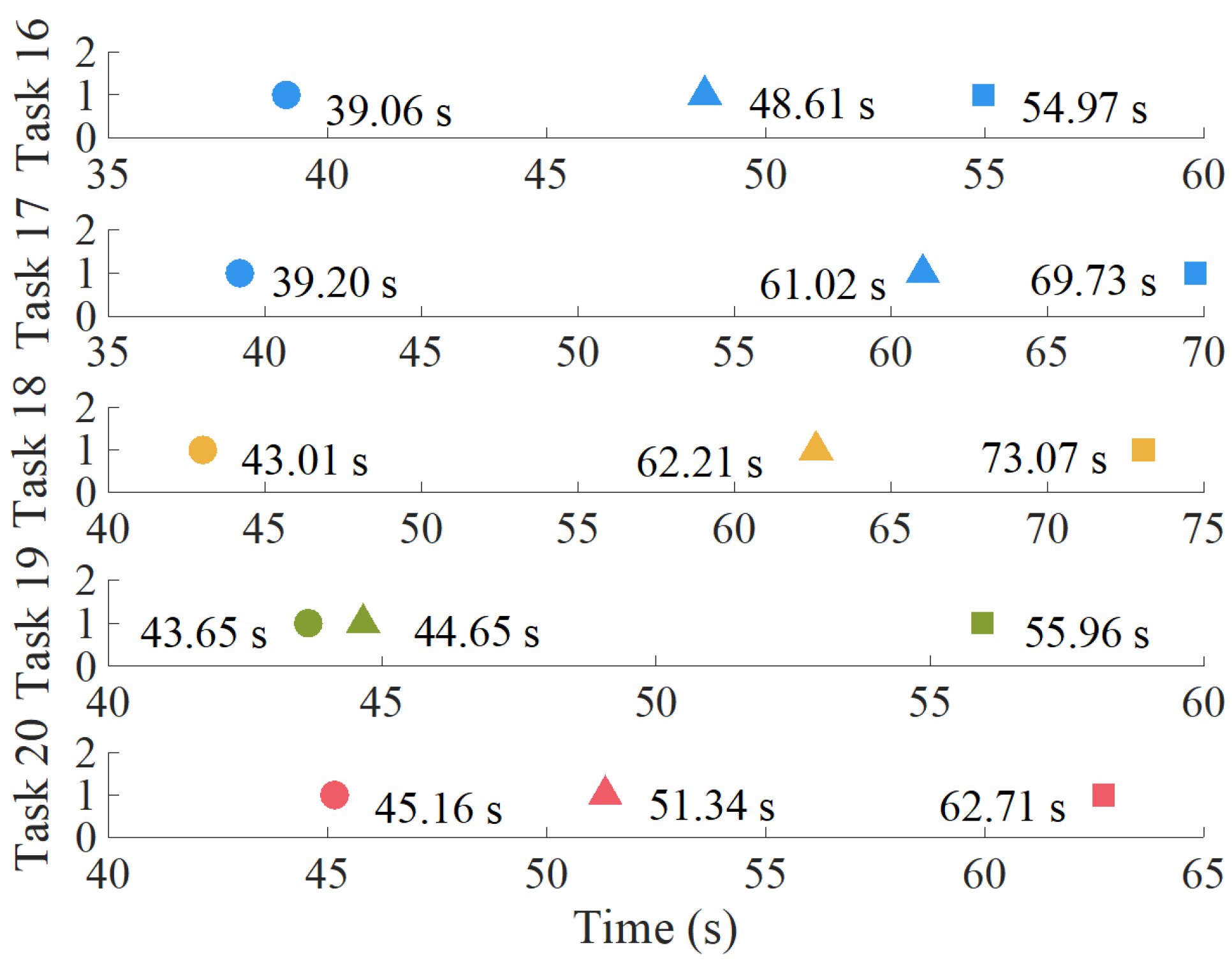
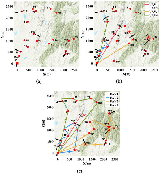
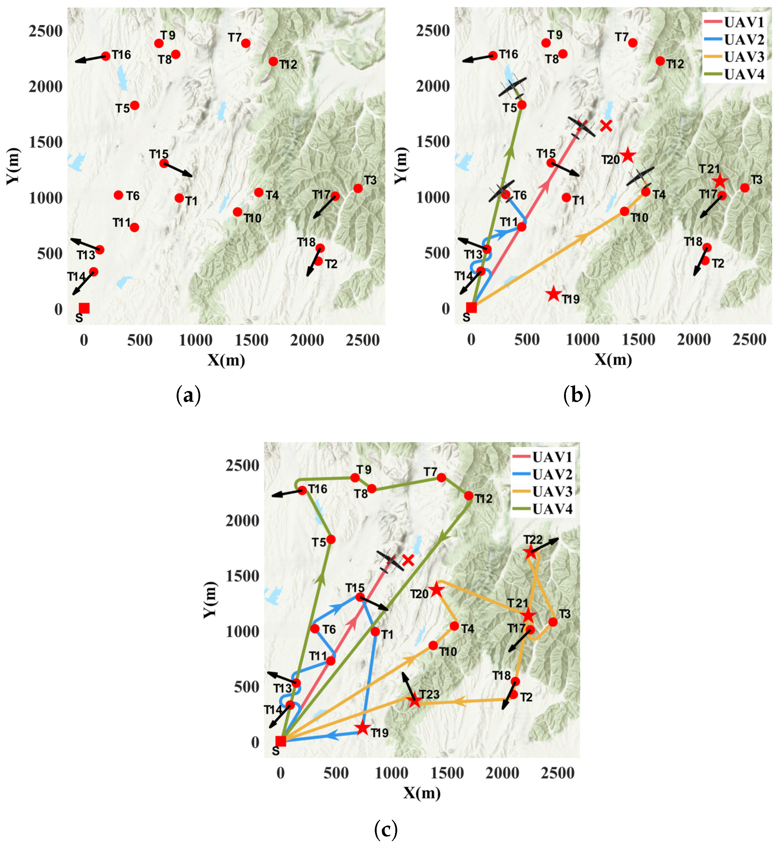
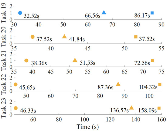
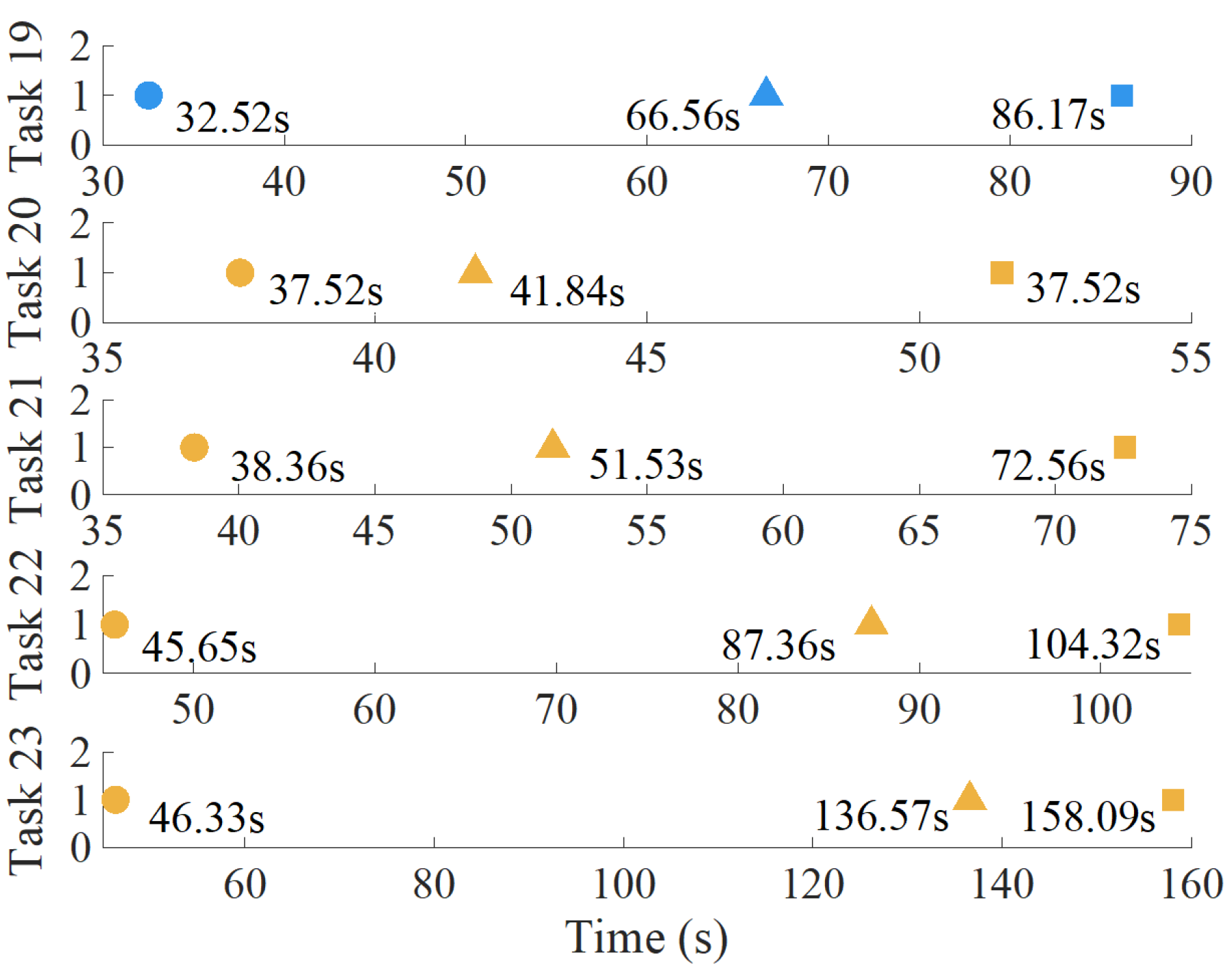
This section demonstrates that the proposed method can be applied to composite scenarios where new tasks arise and UAVs are simultaneously disabled. The scenario involves four UAVs completing 18 randomly generated tasks within a 2.5 km × 2.5 km area. The tasks consist of 12 unconstrained point targets and 6 constrained point targets, as shown in Figure 15a. To simplify the problem, new tasks are randomly generated within the range of motion at time period [30 s–50 s]. Similarly, the new tasks are limited to unconstrained point targets and constrained point targets. It is assumed that none of the new tasks are urgent and that one of the four UAVs is disabled at a random time. Figure 15a–c present the UAV swarm performing its mission at different times when both contingencies exist simultaneously. UAV 1 is disabled at (996.02, 1633.71) in the 40th second. Before the UAV is disabled, a total of three unconstrained point targets (19, 20, 21) appear. These are assigned to UAVs 2 and 3. UAV 1 is disabled on its way to task 7 and has not completed a single task. Afterward, the task cluster comprising task 7 and task 12, originally assigned to UAV 1, is reassigned to UAV 4. After the UAV is disabled, two constraint point targets (22, 23) appear, all of which are assigned to UAV 3. The final mission sequences for UAVs 2, 3, and 4 are as follows: 14-13-11-6-15-1-19, 10-4-20-21-17-3-22-18-2-23 and 5-16-9-8-7-12. Figure 16 quantifies in detail the appearance, assignment, and completion time of each new task in the extreme scenario, and also indicates the UAVs that perform each task.
Figure 15.
Completion of tasks by UAV swarm at different times when two emergency situations occur simultaneously. Red pentagrams indicate emerging tasks. The red cross next to the UAV indicates that the UAV is disabled: (a) t = 0 s; (b) t = 44.12 s; (c) t = 208.10 s.
Figure 16.
New task appearance, allocation, and completion time in the extreme scenario. Task appearance, allocation and completion are represented by circles, triangles and rectangles respectively. Blue, yellow indicate that the tasks are performed by UAVs 2 and 3, respectively.
7. Conclusions and Future Work
This paper proposes a dynamic, real-time, multi-UAV cooperative mission planning method, which is slightly improved to handle emergency situations. The method has four distinctive features: real-time planning without predefined task sequences and paths before take-off; preprocessing of task clustering by proximity criterion; adoption of Dubins path distance cost; and an alternative low-complexity task assignment strategy. These technical features allow the algorithm to perform real-time coupled task assignment and path planning under various constraints, such as heterogeneous tasks, nonholonomic kinematic constraints, limited time, and emergency, while making the total distance as short as possible. The following conclusions are drawn from the experiments:
- (1)
- Our assignment comparison experiment illustrates that mission planning algorithms applying different distance costs result in different allocation schemes. Furthermore, our experiments reveal the mechanism by which the additional distance caused by heading angle correction affects task allocation, as well as the conditions under which it is effective.
- (2)
- Our spatial comparison experiments not only verify that the proposed method can obtain suboptimal solutions, but also reveal the mechanism by which it can achieve near–optimal solutions. Our time experiments show that the proposed algorithm offers significant advantages over traditional distributed intelligence algorithms in terms of total and single planning time, achieving mission planning in around s.
- (3)
- Our scalability experiments demonstrate that the proposed method is highly scalable and can be easily scaled to a large or even extremely large number of mission scenarios in a negligible amount of time.
- (4)
- Our three distinct emergency experiments validate the excellent robustness and adaptability of the variants based on the proposed algorithm.
Even though the proposed algorithm provides encouraging preliminary results, it relies on certain simplifying assumptions that warrant further investigation, thereby outlining key directions for future works. Future work will focus on addressing obstacle avoidance and collisions between UAVs of the same altitude. The proposed method can serve as an upper-layer planner responsible for global task allocation and outputting Dubins reference paths. The lower layer consists of an obstacle avoidance method that can perform local trajectory replanning based on the current state, ensuring flight safety and eventual convergence back to the global path. To further enhance the adaptability of the method, future work should consider UAVs’ varying payloads, ranges, and speeds, complex missions requiring multi-UAV cooperation, as well as the urgency and time constraints of missions. In addition, real physics experiments and learning-based mission planning are also future research topics.
Author Contributions
Conceptualization, C.L. and Y.L.; formal analysis, C.L.; investigation, C.L.; methodology, C.L., Y.L., F.X., T.J. and Y.Z.; project administration, T.J.; resources, T.J.; software, C.L. and Y.L.; supervision, T.J., Y.Z. and F.X.; validation, C.L. and Y.L.; writing—original draft, C.L.; writing—review and editing, F.X., Y.Z. and T.J. All authors have read and agreed to the published version of the manuscript.
Funding
This work was supported by the Zhejiang Province Pioneer Technology Program Project under Grant 2025C01014.
Institutional Review Board Statement
Not applicable.
Informed Consent Statement
Not applicable.
Data Availability Statement
The data that support the findings of this study are available from the corresponding author upon reasonable request.
Acknowledgments
The authors would like to acknowledge the support of Yifeng Yu during the flight Simulation.
Conflicts of Interest
The authors declare no conflicts of interest.
Abbreviations
The following abbreviations are used in this manuscript:
| UAV | unmanned aerial vehicle |
| MTSP | multiple traveling salesman problem |
| SA | simulated annealing algorithm |
| GBA | greedy-based task assignment approach with Euclidean distance |
| HBA | Hungarian-based approach with Euclidean distance |
| AA | auction-based approach with Euclidean distance |
| PRBDD | preprocessing-enabled real-time mission planning method based on Dubins path distance |
| RBDD | real-time mission planning method based on Dubins path distance |
References
- Peng, H.; Li, Z.; Zou, X.; Wang, H.; Xiong, J. Research on litchi image detection in orchard using UAV based on improved YOLOv5. Expert Syst. Appl. 2025, 263, 125828. [Google Scholar]
- Alqudsi, Y.; Makaraci, M. UAV swarms: Research, challenges, and future directions. J. Eng. Appl. Sci. 2025, 72, 12. [Google Scholar] [CrossRef] [Scilit]
- Xu, Y.; Xie, J.; Guo, G. Enhancing Transportation Reliability: Refined Fault-Tolerant Control for Fixed-Wing AAVs Under Constraints and Actuator Imperfections. IEEE Trans. Intell. Transp. Syst. 2025, 26, 17027–17040. [Google Scholar] [CrossRef] [Scilit]
- Zhang, J.; Huang, H. Safe flight corridor constrained sequential convex programming for efficient trajectory generation of fixed-wing UAVs. Chin. J. Aeronaut. 2025, 38, 103174. [Google Scholar]
- Sawadsitang, S.; Niyato, D.; Tan, P.S.; Wang, P.; Nutanong, S. Shipper cooperation in stochastic drone delivery: A dynamic Bayesian game approach. IEEE Trans. Veh. Technol. 2021, 70, 7437–7452. [Google Scholar] [CrossRef] [Scilit]
- Wang, Y.; Shi, Y.; Liu, Y. Research on improved genetic simulated annealing algorithm for multi-UAV cooperative task allocation. J. Phys. Conf. Ser. 2022, 2246, 012081. [Google Scholar] [CrossRef] [Scilit]
- Li, Y.; Wang, S.; Zhou, S.; Wang, Z. A mathematical formulation and a tabu search heuristic for the joint vessel-UAV routing problem. Comput. Oper. Res. 2024, 169, 106723. [Google Scholar] [CrossRef] [Scilit]
- Zhang, X.; Zhang, F.; Tang, Z.; Chen, X. A MILP model on coordinated coverage path planning system for UAV-ship hybrid team scheduling software. J. Syst. Softw. 2023, 206, 111854. [Google Scholar] [CrossRef] [Scilit]
- Andersen, A.C.; Pavlikov, K.; Toffolo, T.A.M. Weapon-target assignment problem: Exact and approximate solution algorithms. Ann. Oper. Res. 2022, 312, 581–606. [Google Scholar] [CrossRef] [Scilit]
- Samiei, A.; Ismail, S.; Sun, L. Cluster-based hungarian approach to task allocation for unmanned aerial vehicles. In Proceedings of the 2019 IEEE National Aerospace and Electronics Conference (NAECON), Dayton, OH, USA, 15–19 July 2019; pp. 148–154. [Google Scholar]
- Wang, C.; Mu, D.; Zhao, F.; Sutherland, J.W. A parallel simulated annealing method for the vehicle routing problem with simultaneous pickup–delivery and time windows. Comput. Ind. Eng. 2015, 83, 111–122. [Google Scholar] [CrossRef] [Scilit]
- Wang, G.; Wang, F.; Wang, J.; Li, M.; Gai, L.; Xu, D. Collaborative target assignment problem for large-scale UAV swarm based on two-stage greedy auction algorithm. Aerosp. Sci. Technol. 2024, 149, 109146. [Google Scholar]
- Deng, R.; Yan, R.; Huang, P.; Shi, Z.; Zhong, Y. A Distributed Auction Algorithm for Task Assignment with Robot Coalitions. IEEE Trans. Robot. 2024, 40, 4787–4804. [Google Scholar] [CrossRef] [Scilit]
- Yan, F.; Chu, J.; Hu, J.; Zhu, X. A Cooperative task allocation with simultaneous arrival and resource constraint for multi-UAV using a genetic algorithm. Expert Syst. Appl. 2024, 245, 123023. [Google Scholar]
- Zhai, S.; Li, G.; Wu, G.; Jia, Q. Cooperative task allocation for multi heterogeneous aerial vehicles using particle swarm optimization algorithm and entropy weight method. Appl. Soft. Comput. 2023, 148, 110918. [Google Scholar] [CrossRef] [Scilit]
- Moon, B.H.; Ji, J.H.; Lee, H.J.; Aye Maw, A.; Lee, J. Cooperative Mission Allocation in MUM-T Search and Destroy Operation with Transformer-Based Deep Reinforcement Learning. In AIAA SCITECH 2025 Forum; AIAA: Reston, VA, USA, 2025; pp. 1612–1628. [Google Scholar]
- Yue, W.; Zhang, X.; Liu, Z. Distributed cooperative task allocation for heterogeneous UAV swarms under complex constraints. Comput. Commun. 2025, 231, 108043. [Google Scholar] [CrossRef] [Scilit]
- DeGroote, N.S.; Cohen, K. Cooperative Multi-Agent UAS Task Assignment for Disaster Response Scenario. In AIAA SCITECH 2022 Forum; AIAA: Reston, VA, USA, 2022; p. 0792. [Google Scholar]
- Zhang, Z.; Jiang, J.; Zhang, W.A. Distributed dynamic task allocation for unmanned aerial vehicle swarm systems: A networked evolutionary game-theoretic approach. Chin. J. Aeronaut. 2024, 37, 182–204. [Google Scholar]
- Zhang, J.; Cui, Y.; Ren, J. Dynamic mission planning algorithm for UAV formation in battlefield environment. IEEE Trans. Aerosp. Electron. Syst. 2022, 59, 3750–3765. [Google Scholar] [CrossRef] [Scilit]
- Zhang, C.; Guo, J.; Wang, F.; Chen, B.; Fan, C.; Yu, L.; Wang, Z. A dynamic parameters genetic algorithm for collaborative strike task allocation of unmanned aerial vehicle clusters towards heterogeneous targets. Appl. Soft. Comput. 2025, 175, 113075. [Google Scholar] [CrossRef] [Scilit]
- Wang, Z.; Liu, L.; Long, T.; Wen, Y. Multi-UAV reconnaissance task allocation for heterogeneous targets using an opposition-based genetic algorithm with double-chromosome encoding. Chin. J. Aeronaut. 2018, 31, 339–350. [Google Scholar] [CrossRef] [Scilit]
- Cho, D.H.; Jang, D.S.; Choi, H.L. Memetic algorithm-based path generation for multiple Dubins vehicles performing remote tasks. Int. J. Syst. Sci. 2020, 51, 608–630. [Google Scholar] [CrossRef] [Scilit]
- Chen, Y.; Yang, D.; Yu, J. Multi-UAV task assignment with parameter and time-sensitive uncertainties using modified two-part wolf pack search algorithm. IEEE Trans. Aerosp. Electron. Syst. 2018, 54, 2853–2872. [Google Scholar] [CrossRef] [Scilit]
- Gao, X.; Wang, L.; Su, X.; Lu, C.; Ding, Y.; Wang, C.; Peng, H.; Wang, X. A unified multi-objective optimization framework for UAV cooperative task assignment and re-assignment. Mathematics 2022, 10, 4241. [Google Scholar] [CrossRef] [Scilit]
- Wu, J.; Zhang, J.; Sun, Y.; Li, X.; Gao, L.; Han, G. Multi-UAV collaborative dynamic task allocation method based on ISOM and attention mechanism. IEEE Trans. Veh. Technol. 2023, 73, 6225–6235. [Google Scholar] [CrossRef] [Scilit]
- Cui, Y.; Chen, J.; Lin, H.; Shu, Z.; Huang, T. Cooperative Multi-AAV Path Planning for Discovering and Tracking Multiple Radio-Tagged Targets. IEEE Trans. Syst. Man Cybern.-Syst. 2025, 55, 2463–2475. [Google Scholar] [CrossRef] [Scilit]
- Cui, Y.; Wang, J.; Zheng, C.; Lin, H.; Feng, Z.; Huang, T. Adaptive Risk-Aware Multi-Target Tracking and Monitoring with Network Reconfiguration. IEEE Trans. Circuits Syst. I Regul. Pap. 2025, 72, 8273–8286. [Google Scholar] [CrossRef] [Scilit]
- Liu, C.; Xie, F.; Ji, T. Fixed-wing uav formation path planning based on formation control: Theory and application. Aerospace 2023, 11, 1. [Google Scholar] [CrossRef] [Scilit]
- Manyam, S.G.; Rathinam, S.; Casbeer, D.; Garcia, E. Tightly bounding the shortest dubins paths through a sequence of points. J. Intell. Robot. Syst. 2017, 88, 495–511. [Google Scholar] [CrossRef] [Scilit]

Disclaimer/Publisher’s Note: The statements, opinions and data contained in all publications are solely those of the individual author(s) and contributor(s) and not of MDPI and/or the editor(s). MDPI and/or the editor(s) disclaim responsibility for any injury to people or property resulting from any ideas, methods, instructions or products referred to in the content. |
© 2026 by the authors. Licensee MDPI, Basel, Switzerland. This article is an open access article distributed under the terms and conditions of the Creative Commons Attribution (CC BY) license.