Abstract
A Micro Electro-Mechanical System (MEMS) that allows to measure an external force applied to a probe tip exploiting an electrical servo-assisted mechanism based on position feedback is presented. The sensor architecture keeps the position of the probe tip fixed by driving a pair of variable-area electrostatic actuators in a feedback loop controlled by a variable-gap capacitive sensor. By adjusting specific loop parameters, the force sensitivity can be finely tuned electrically. Sub-nanonewton measurement range is achieved with high flexibility in setting the tip working point, making the system promising for measuring forces generated by living biological cells.
1. Introduction
Forces generated by living cells are indicators of their state of evolution and can be critical regulators of cell adhesion processes [1]. Microsystems for measuring forces and mechanical properties of different materials at micro/nanoscale have gained an important role for probing biological samples in in vitro mechanobiology experiments [2,3]. In particular, the measurement of minute forces without requiring an associated displacement is a critical task. A common drawback in force sensors is the inherent trade-off between the measurement range and sensitivity. Typically, MEMS force sensors do not exhibit the ability to adapt the range and sensitivity depending on the external applied force [4], which instead would be a desirable feature in many applications. The MEMS force sensor, here presented, allows tunable measurement range and sensitivity, exploiting an electrical servo-assisted mechanism with position-feedback [5] to keep the mechanical structure in a fixed position thus allowing to measure an applied external force offering a virtually infinite mechanical impedance. The device description and operating principle are illustrated in Section 2, experimental results are presented in Section 3, and conclusions are given in Section 4.
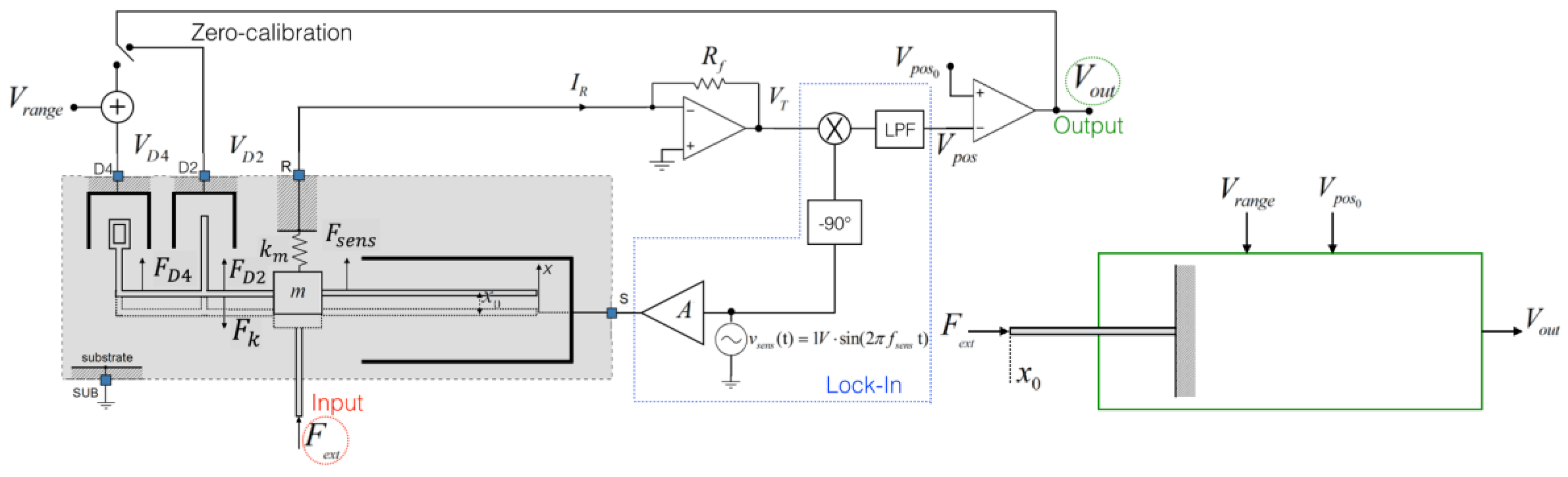
2. Servo-Assisted Position-Feedback MEMS Force Sensor
The block diagram of the system is shown in Figure 1, while images of the fabricated MEMS are shown in Figure 2a. The input voltage sets the range and sensitivity of force measurement, while the input voltage sets the position that represents the working point of the probe tip.
Figure 1.
Block diagram of the servo-assisted position-feedback MEMS force sensor.
Figure 2.
(a1) Image of the fabricated MEMS device with (a2) enlarged views of the probe tip; (a3) driver D4; (a4) driver D2 and capacitive position sensor ; (b1) Experimental setup with (b2) enlarged views of the force sensor under test; (b3) the transimpedence amplifier and (b4) the rotating stage.
The static equilibrium of all forces acting on the shuttle R integral with the tip, without an applied external force , leads to:
where and represent the electrostatic forces generated by the variable-area driving actuators D2 and D4; and represent the electro-mechanical transduction factors of the two drivers, respectively [2]. The contribution represents the elastic force of the suspending springs, while is the electrostatic force generated by the voltage required to measure the variable-gap comb sensing capacitance employing a transimpedance amplifier (OPA656) and a lock-in amplifier (Stanford SR850). The sensing voltage , with = 1 Vpeak, is internally downscaled by A = 0.1 to set to 0.1 Vpeak, so to prevent pull-in. The sensing frequency is set to 100 kHz far from the resonant mechanical frequency at around 2 kHz.
The initial zero-calibration procedure nulls the output voltage thanks to the zero-calibration feedback loop that modulates the voltage .
The feedback loop imposes , where is the output voltage of the transimpedance amplifier which, thanks to the lock-in amplifier, it results linearly dependent to the sensing capacitance and related to the position as follows:
where is the feedback resistance of the transimpedance amplifier and k = 1 V−1 is the scale factor of the lock-in amplifier. This procedure allows to select the required voltage , and thereafter, to set the required working point by adjusting the voltage . This ensures that with = 0, given the required range and sensitivity, the probe tip is fixed at a desired position resulting in = 0.
Once the zero-calibration procedure has ended, the voltage is kept constant, and the feedback loop is switched to the driver D4 in order to measure the external force . The position-feedback loop keeps the probe tip fixed at the working position regardless of the applied force , producing an equivalent infinite mechanical impedance, i.e. unlimited stiffness. Considering the equilibrium of all forces acting on the device, including the external force, results in:
Linearizing around the working point, it follows that:
where is the force sensitivity of the system.
Considering a non-linearity error of 1% of the span, the corresponding measurement range is . In such a range the output voltage is linearly related to the applied force within an error of 1%, while the measurement range and sensitivity depend only on the voltage .
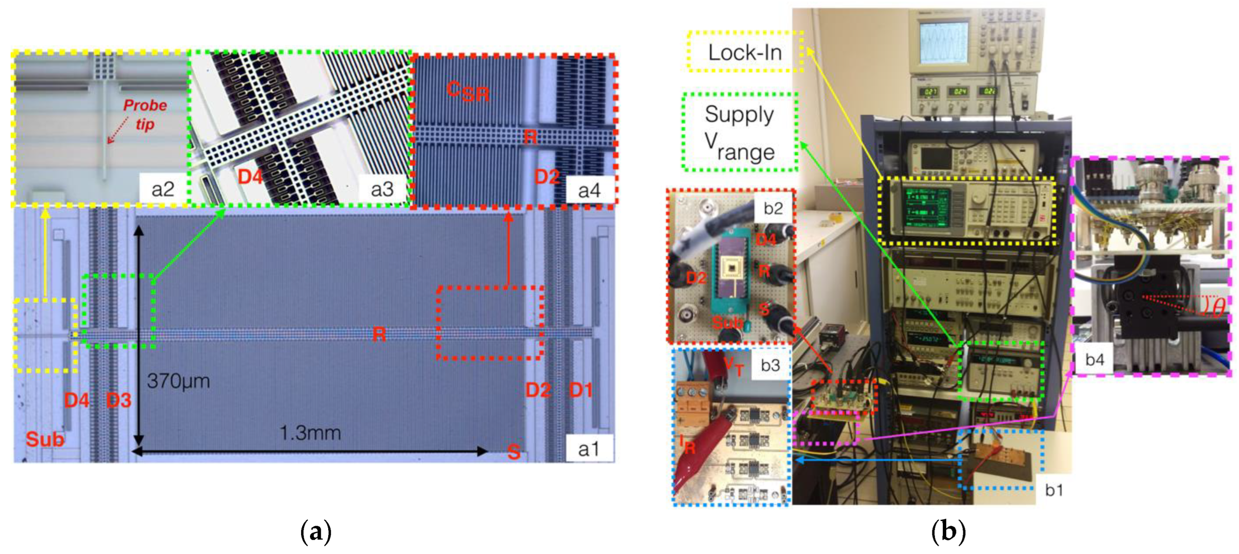
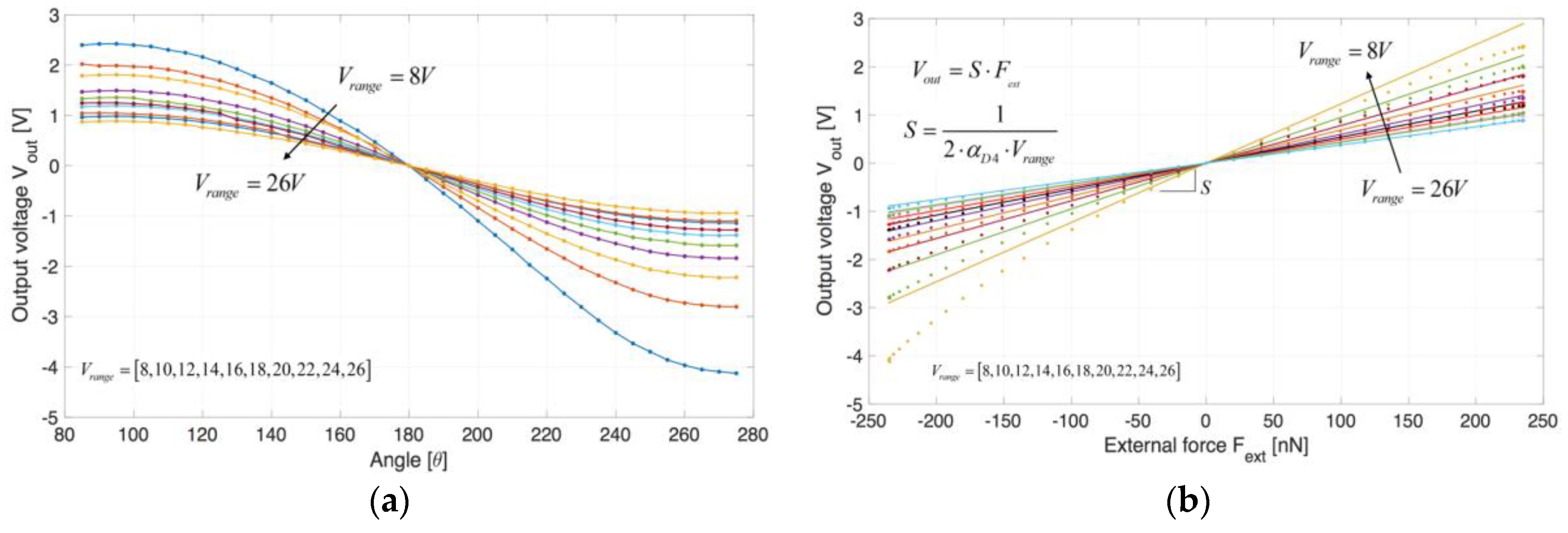
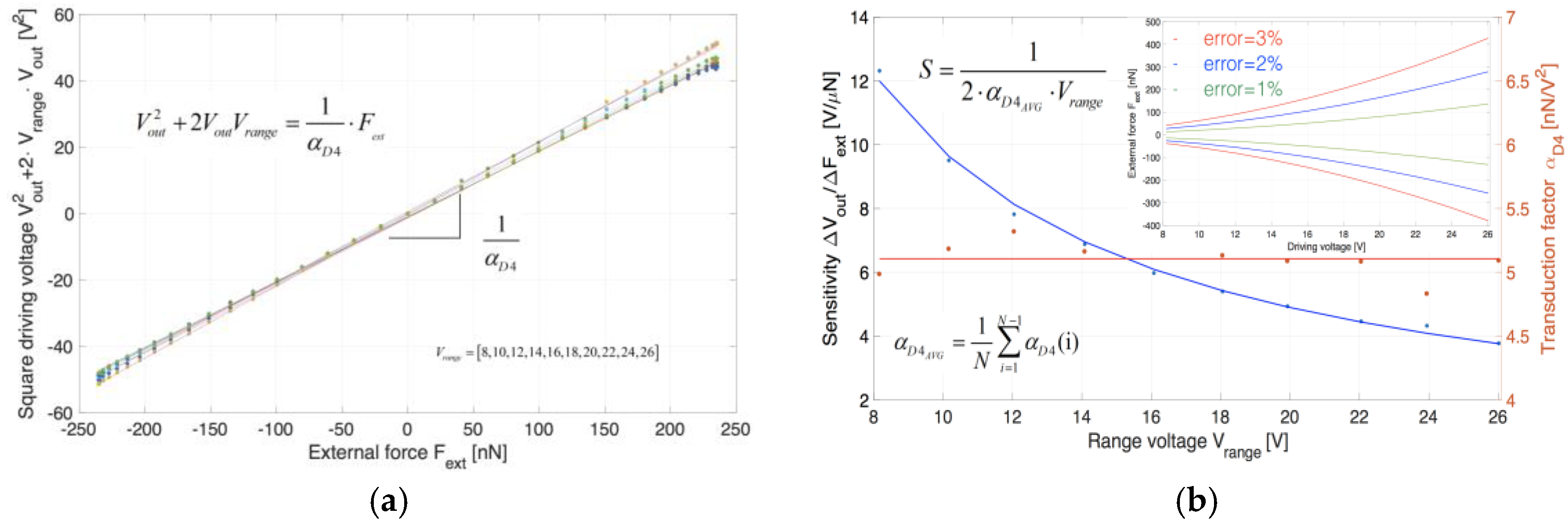
3. Experimental Results
Figure 2b shows the setup used to test the device. The weight force controlled by inclination through a motorized ThorLabs MDT693B rotating stage was used as the external reference force. This results in = mg sin(θ) where m = 24 μg is the mass of the movable shuttle, g = 9.81 m/s2 is the gravitational acceleration and θ is the inclination angle. Figure 3a,b show the measured output voltage as a function of angle and external force , respectively. In Figure 4a it is represented the sum as a function of from which it is possible to estimate . Figure 4b reports the sensitivity S and the transduction factor derived from fitting of Figure 4a as function of the input voltage . Experimental results are in good agreement with the theoretical values of S obtained using the average value of . The inset of Figure 4b shows the measurement range of the external forces considering a non-linearity error lower than 1%, 2% and 3%. Incremental angles corresponding to 0.4 nN forces where consistently detected, leading to a sub-nanonewton resolution.
Figure 3.
(a) Measured output voltage as a function of the angle θ of the rotating stage for different values of ; (b) Measured output voltage as a function of the external weight force for different values of . Raw data are represented with dots while lines represent a fitting with a polynomial of 1st order.
Figure 4.
(a) The estimation of the electro-mechanical transduction factor ; (b) Sensitivity S and electro-mechanical transduction factor as function of . Red line represents the average value of while blue line is the calculated sensitivity. The inset of Figure 4b shows the range of measurable external forces with non-linearity error of 1%, 2% and 3% of the span.
4. Conclusions
A MEMS force sensor that allows to measure an external force applied to a probe tip with tunable sensitivity exploiting an electrical servo-assisted mechanism based on position feedback has been presented. The servo-assisted feedback-position mechanism keeps the position of the probe tip fixed by driving a pair of variable-area electrostatic actuators in a feedback loop controlled by a variable-gap capacitive sensor offering a virtually infinite mechanical impedance. By adjusting specific loop parameters, the force sensitivity S and the working position can be finely tuned electrically. The experimental results show that the proposed system has the capability of measuring forces in the nanonewton to sub-nanonewton range with sensitivity of up to 12 V/μN () with high flexibility in the setting the tip working point, thereby making the system suitable for biological force probing.
Conflicts of Interest
The authors declare no conflict of interest.
References
- Polacheck, W.J.; Chen, C.S. Measuring cell-generated forces: A guide to the available tools. Nat. Methods 2015, 13, 415–423. [Google Scholar] [CrossRef] [PubMed]
- Cerini, F.; Ferrari, M.; Ferrari, V.; Russo, A.; Azpeitia Urquia, M.; Ardito, R.; De Masi, B.; Serzanti, M.; Dell’Era, P. MEMS force microactuator with displacement sensing for mechanobiology experiments. AEIT Int. Annu. Conf. 2015, 7415224, 1–6. [Google Scholar] [CrossRef]
- Beyeler, F.; Muntwyler, S.; Nelson, B.J. A six-axis MEMS force-torque sensor with micro-newton and nano-Newtonmeter resolution. J. Microelectromech. Syst. 2009, 18, 433–441. [Google Scholar] [CrossRef]
- Keekyoung, K.; Ji, C.; Qun, L.; Xiao, Y.W.; Yu, S. Investigation of mechanical properties of soft hydrogel microcapsules in relation to protein delivery using a MEMS force sensor. J. Biomed. Mater. Res. A 2010, 92, 103–113. [Google Scholar] [CrossRef]
- Moore, S.I.; Coskun, M.B.; Alan, T.; Neild, A.; Moheimani, S.O.R. Feedback-Controlled MEMS Force Sensor for Characterization of Microcantilevers. J. Microelectromech. Syst. 2014, 24, 1092–1101. [Google Scholar] [CrossRef]
Publisher’s Note: MDPI stays neutral with regard to jurisdictional claims in published maps and institutional affiliations. |
© 2017 by the authors. Licensee MDPI, Basel, Switzerland. This article is an open access article distributed under the terms and conditions of the Creative Commons Attribution (CC BY) license (https://creativecommons.org/licenses/by/4.0/).