1. Introduction
In many application fields, such as aerospace and lithography, high-precision displacement sensors are utilised. If a high resolution over only a short displacement range is required, often capacitive sensors are selected. An important limitation of capacitive sensors, however, is their sensitivity to environmental conditions, such as contamination and humidity of the ambient air [
1].
As an alternative to capacitive sensors, Eddy-Current Displacement Sensors (ECDSs) can be utilised, but state-of-the-art industrial sensors typically have a relatively poor stability and a low resolution, due to their relatively low excitation frequency of up to several megahertz. These limitations can be mitigated by using a much higher excitation frequency, i.e., above 100 MHz [
2,
3]. In our earlier work, an ECDS was developed that uses an excitation frequency of 126 MHz. The sensor achieves a resolution of 0.6 nm at 2 kHz signal bandwidth [
4].
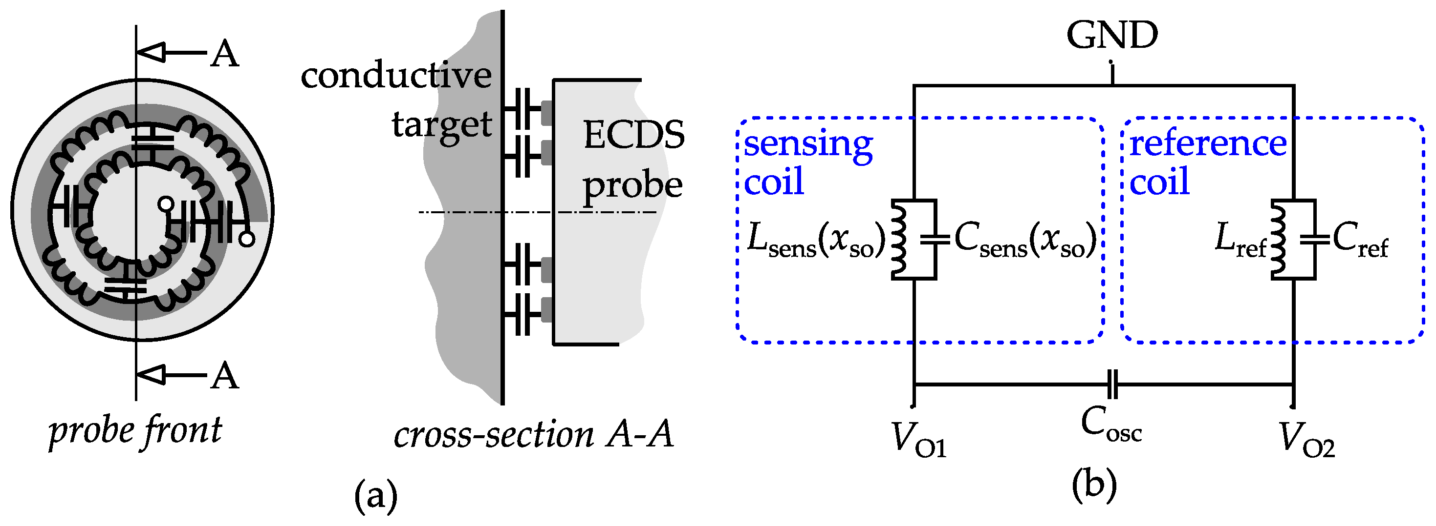
The developed ECDS uses the inductance of the sensing coil as a measure of standoff distance from the conductive target. Apart from inductance, the coil also exhibits parasitic interwinding capacitance (
Figure 1a), leading to a certain Self-Resonance Frequency (SRF) [
5]. Unfortunately, this capacitance is sensitive to changes in the relative permittivity [
6]. This paper studies how humidity change influences the displacement measurement and shows how the required coil SRF relates to specifications regarding allowable humidity variation and displacement measurement error.
In
Section 2, the sensor’s sensitivity to parasitic capacitance change is analysed using circuit theory.
Section 3 studies the sensitivity to humidity change using a combination of analytic equations and finite element modelling.
2. Sensitivity to Parasitic Capacitance Change
Figure 1b shows the circuit of the sensor’s self-oscillating frontend reported in [
4]. It consist of a sensing coil, a reference coil and an on-chip capacitor (
) that together form an oscillator. The inductance of the sensing coil is a measure for the standoff
from a conductive measurement target. The reference coil is placed at a fixed standoff from a reference target.
The electronic readout measures the reactance of each coil, which not only depends on the inductance, but also on the lumped parasitic capacitances of the coil. The inductance and parasitic capacitance of the sensing coil are both a function of the standoff; frequency dependency is neglected.
The sensing coil has an impedance of
and a SRF of
Assuming that the movement of measurement target with respect the sensing coil is relatively small compared to the nominal standoff, their inductance and their parasitic capacitance can be assumed to be almost equal, so that
and
. The total impedance of the coils is then
leading to an excitation frequency of
.
If the humidity of the environment changes, the capacitance of the sensing coil changes, but the capacitance of the reference coil remains constant. Thus, the capacitance change of the sensing coil directly leads to a measurement error. Neglecting the relatively small change of the excitation frequency, the sensitivity of the impedance to the sensing coil’s parasitic capacitance becomes
where
denotes the SRF normalised by the excitation frequency (both in rad/s). The resulting displacement error can be derived by converting Equation (3) to equivalent inductance and dividing it by the displacement sensitivity (
):
3. Sensitivity to Humidity Variation
To obtain the sensitivity of the displacement measurement to humidity variation, the sensitivity need to be found. can be decomposed into the sensitivities and , with the relative permittivity of the air volume, which changes with humidity, and the relative humidity in percent.
Lea et al. derived the following relation for the relative permittivity of humid air [
7]:
with
,
,
the temperature in Kelvin and
the vapour pressure of water, which can be calculated using the August-Roche-Magnus formula [
8]:
Thus, at room temperature (), the sensitivity of the relative permittivity to the relative humidity is .
If the relative permittivity of all the surroundings of the coil would be equal and would change equally with humidity, the capacitance would change according to , with the nominal capacitance of the coil and the nominal relative permittivity of the surroundings. However, for a coil attached to a probe, these conditions are not met. Typically, the of the probe material is different from the one of air gap and is ideally not influenced by humidity change. To account for these effects, a constant that depends on the geometry and materials of the probe is introduced, so that the equation becomes , with the relative permittivity of the air gap.
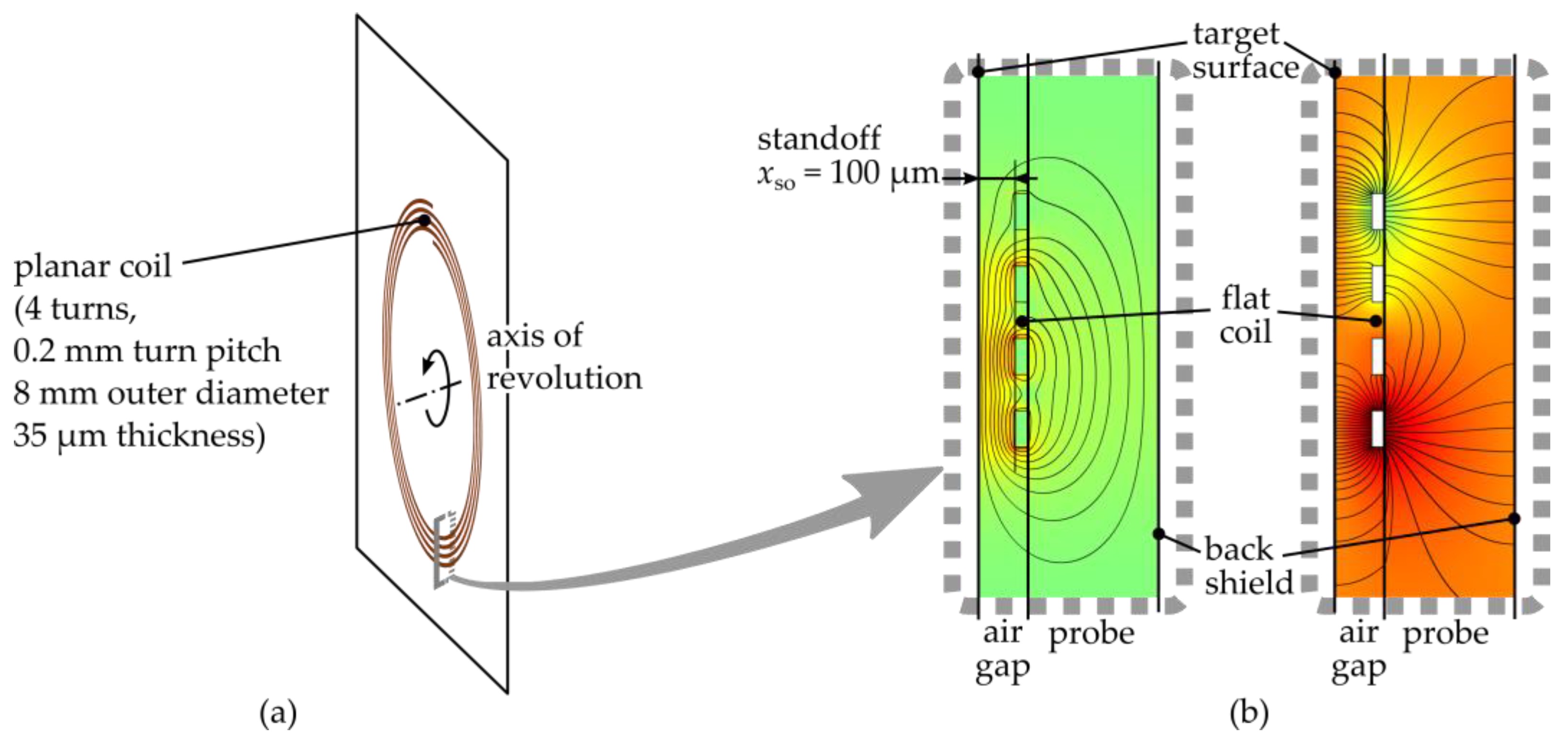
As an example, a probe with the coil of
Figure 2a was modelled. The probe is located at a 100 µm standoff from the target and is made of FR4 PCB material. At 360 µm from the back of the coil a shield is placed.
Figure 2b shows the magnetic and electric field corresponding to the SRF of the coil, as calculated using a finite element model in Comsol. The coil has a lumped capacitance of
and a sensitivity of
pF, leading to
.
The sensitivity of the capacitance to humidity can be expressed as
Combining Equations (4) and (7), the allowable humidity variation (in percent) as function of the ratio between the SRF and the excitation frequency is
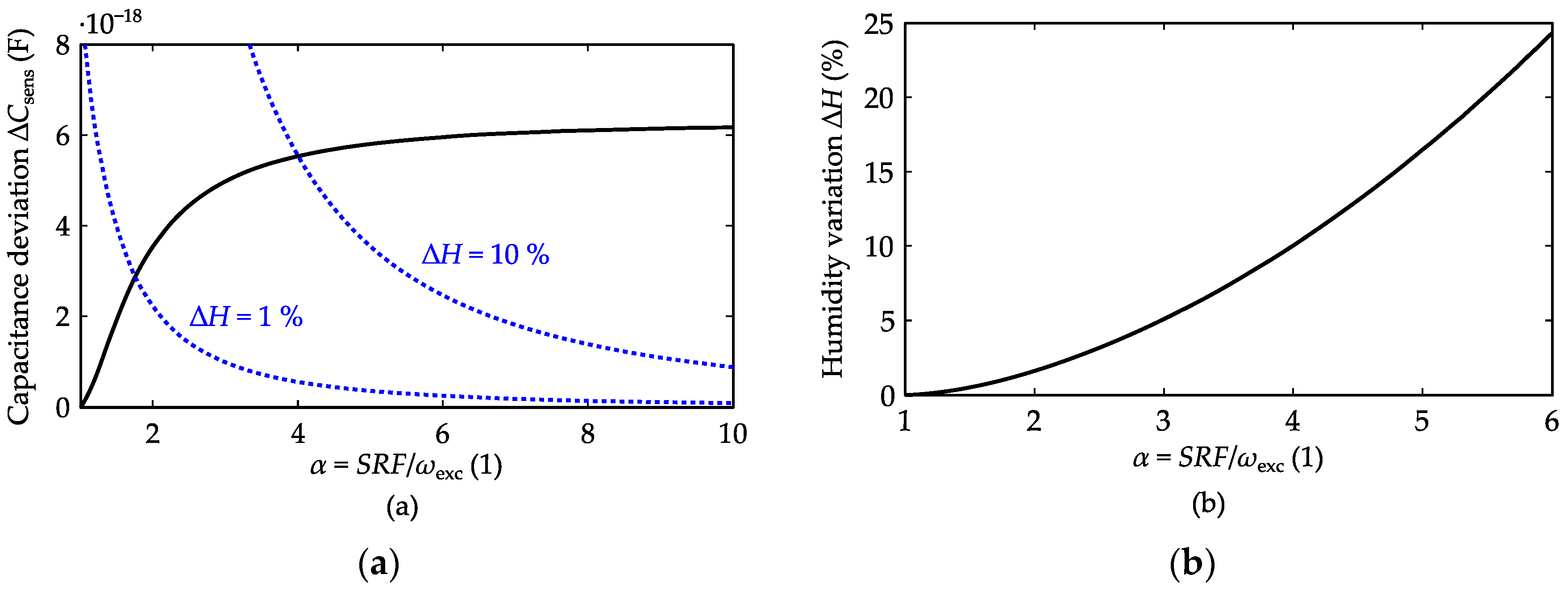
Figure 3a shows the capacitance deviation that leads, for the selected coil geometry, to a 0.1 nm measurement error, as a function of the normalised SRF (solid line). Also the capacitance deviation resulting from a humidity deviation of 1% and 10% is shown (dashed lines).
Figure 3b provides the allowed humidity range as a function of the normalised SRF. For a relative humidity variation of 1% and 10%, respectively, the SRF should be 1.8 and 4.0 times higher than the excitation frequency.
4. Conclusions
An important benefit of ECDSs over capacitive sensors is their insensitivity to environmental conditions. ECDSs that measure the reactance of the sensing coil, however, can not distinguish a change of the coil’s parasitic capacitance from a change in the coil’s inductance, leading to a certain sensitivity to environmental conditions.
The parasitic capacitance of the sensing coil can be characterised using the coil’s SRF. An expression is derived for the humidity variation that leads to certain error on the displacement measurement. The expression depends, amongst others, on the ratio between the SRF and the excitation frequency. The knowledge of this relation allows to make a trade-off between the SRF and the humidity specifications of the sensor and can be used as input for the coil and probe design.
