Article

Improving Electrochemical Performance of Cobalt Hexacyanoferrate as Magnesium Ion Battery Cathode Material by Nickel Doping

1
College of Materials Science and Engineering, Chongqing University, Chongqing 400044, China
2
Chongqing Institute of New Energy Storage Materials and Equipment, Chongqing 400015, China
*
Authors to whom correspondence should be addressed.
Batteries 2025, 11(6), 213; https://doi.org/10.3390/batteries11060213
Submission received: 23 April 2025 / Revised: 15 May 2025 / Accepted: 25 May 2025 / Published: 29 May 2025

Abstract

:
Magnesium metal has a high theoretical volume capacity and abundant reserves. Magnesium ion battery is theoretically secure and eco-friendly. In recent years, magnesium ion battery has attracted wide attention and is expected to become a competitive energy storage candidate in the next generation. However, due to the large polarization effect and slow migration kinetics of magnesium ions, magnesium ions are hard to insert/desert in cathode materials, resulting in a poor cycle and rate performance. CoHCF, a typical Prussian blue analog, has an open frame structure and double REDOX sites, and it is regarded as a candidate for rechargeable ion battery. Herein, a Ni-doping method was utilized to improve the performance of CoHCF. Compared with the original CoHCF, the maximum specific discharge capacity of the Ni-doped CoHCF at 50 mA/g charging and discharging current increased from 70 mAh/g to 89 mAh/g, and the cyclic performance and rate performance improved. These improvements result from the fact that the electrode reaction process of Ni-doped CoHCF changes from diffusion-driven to reaction-driven. The Ni-doped CoHCF is more stable, and the lattice changes during Mg2+ (de-)intercalation are smaller. This study can provide a reference for the development of Prussian blue analogs as cathode materials for magnesium ion batteries.

1. Introduction

In recent years, magnesium ion batteries (MIBs) have attracted great attention from researchers, and they are expected to become a competitive energy storage candidate in the next generation. This is because MIB has two outstanding advantages. First, magnesium metal has a high theoretical volume specific capacity (3833 mAh/cm3), low standard potential (−2.37 V vs. SHE), and an abundant reserve. Second, MIB does not form dendrites on the surface of anodes during charging and discharging, and it is friendly to the environment [1,2,3,4,5,6]. However, compared with lithium ion, magnesium ion has a stronger polarization effect, and it is more difficult for magnesium ion to reversibly (de-)intercalate in an electrode. At present, it is difficult to make MIB achieve a better rate performance and cycle stability [4]. Therefore, the development of high-performance cathode materials has become one of the key tasks for new MIBs [5]. So far, the main materials used as cathode materials for MIBs are transition metal sulfides [7,8,9,10], transition metal oxides [11,12,13,14,15], olivine type [16,17], NASSICON type [18,19], Prussian blue analogs, etc. Among these cathode materials, Prussian blue analogs (PBAs) are selected as cathode materials for MIB due to their high electrochemical window, large open frame structure, and low cost [20,21,22,23,24,25,26,27].
PBAs are a kind of metal–organic framework (MOF) material formed by bridging transition metals through carbon and nitrogen triple bonds. The structure of PBAs is shown in Figure 1. Generally, the chemical formula of PBAs can be written as AxM1[M2(CN)6]y•□1−y•zH2O, where A represents alkali metal elements (such as Li, Na, K, etc.), M1 and M2 are transition metal elements adjacent to N and C atoms, respectively, and □ is the vacancy of [M2(CN)6]n−. M1 is in a low-spin state, while M2 is in a high-spin state. The spatial structure of PBAs can generally be seen as an alternating composition of two octahedral structures, M1N6 and M2C6 (when M1 and M2 are 6-coordination transition metal elements) [28,29,30,31]. According to whether M1 participates in a REDOX reaction during a charge and discharge, it can be divided into two categories: one is transition metal elements represented by Fe, Co, Mn, etc. These elements participate in the REDOX reaction and provide about half of the specific capacity of a charge and discharge [32,33,34]. The other type is the transition metal elements represented by Zn, Ni, Cu, etc. These elements do not participate in the REDOX reaction and, thus, do not provide a specific discharge capacity but may participate in the transmission of electrons in the cathode material [35], thereby improving the rate performance and cycle performance of the battery. Therefore, the element type of transition metal M1 affects the performance of PBAs as cathode materials for ion batteries.
Cobalt hexacyanoferrate (CoHCF) is a two-electron reactive PBA with a high theoretical specific capacity (169.6 mAh/g) [32]. However, the structure of CoHCF is prone to collapse during a charge and discharge, especially in charge and discharge cycles with a high current density, resulting in poor cycle stability and rate performance. The reasons for this phenomenon are as follows. First of all, Fe(CN)6 vacancies are formed easily in the CoHCF preparation process, resulting in the reduction of the whole structural stability. Secondly, as a two-electron REDOX cathode, CoHCF undergoes at least two stages of physicochemical changes during charging or discharging, resulting in greater structural changes. Based on the above factors, the magnification performance and cycle stability of CoHCF as the cathode material of ion batteries are poor. In order to solve this problem, the commonly used method is to improve the crystallinity and structural integrity of CoHCF by reducing the vacancy generation in the synthesis process of CoHCF, so as to improve the magnification performance and cycle stability of CoHCF. For PBAs, the main method to reduce the Fe(CN)6 vacancies is to add chelating agents such as sodium citrate in the process of precipitation. The chelating agents can not only slow down the growth process, but also improve the crystallinity of the product and reduce the generation of vacancies [36]. At the same time, adding excessive alkali metal ions in the synthesis process to promote the charge balance can also effectively reduce the generation of Fe(CN)6 vacancies [37]. In addition to the above methods of precipitation, CoHCF with a low defect can also be obtained by electrospinning [38], co-precipitation-assisted electrochemical synthesis [39], and other methods. In addition to reducing the vacancy formation of the product during the synthesis process, a modification of the macroscopic or microscopic structure of CoHCF can also improve the magnulation performance and cycle stability such as the synthesis of the core-shell structure [40] and assist synthesis with ZIF-67 as the precursor template [41], etc. As a transition metal element, Ni does not participate in the REDOX reaction during a charge and discharge, but it participates in the electron transport process. The electronic conductivity of CoHCF can be improved by the Ni-doping method so as to improve the electrochemical performance of CoHCF as a cathode material for magnesium ion batteries.
In this work, in order to solve the problem of the low cycle stability and rate performance of CoHCF as an MIB cathode material, CoHCF was modified by the Ni-doping method. CoHCF and Ni-doped CoHCF were synthesized by a one-step precipitation method. The structural differences between CoHCF and Ni-doped CoHCF were analyzed by structural characterization, and the electrochemical properties of different CoHCFs as an MIB cathode material in a Mg(TFSI)2/AN electrolyte were studied.

2. Materials and Methods

2.1. Material Preparation

Both CoHCF and Ni-doped CoHCF were prepared by a one-step precipitation method. For CoHCF, cobalt nitrate hexahydrate (Aladdin, Shanghai, China, 99.99%) and sodium citrate hydrated (Tianjin Zhiyuan Reagent Co., Ltd., Tianjin, China, AR) were added to deionized water at a molar ratio of 1:1 (denoted as solution A) and magnetically stirred for 30 min in a water bath at 50 °C. Sodium ferrocyanide decahydrate (Tianjin Berens Biotechnology Co., Ltd., Tianjin, China, AR) and sodium chloride (Chongqing Chuandong Chemical (Group) Co., Ltd., Chongqing, China, AR) were added to 100 mL deionized water at a molar ratio of 1:5 (denoted as solution B) and stirred evenly in a water bath at 60 °C. The molar ratio of hydrated cobalt nitrate to sodium ferrocyanide decahydrate was 1:1. After solution B was stirred evenly, solution A was slowly added to solution B, being stirred with the glue head dropper. After the drip was finished, solution A and solution B were mixed at 60 °C and continued being stirred for 12 h. After stirring, the mixture of solution A and solution B was left to settle at room temperature for 12 h. The obtained sediment was separated by centrifuge and washed three times with water and alcohol continuously, and then dried in a 60 °C drying oven for 12 h. After being dried, the final product was used as the active substance of the battery cathode material. Ni-doped CoHCF was modified by the original CoHCF synthesis method. The configuration method of solution A was that cobalt nitrate hexahydrate, nickel nitrate hexahydrate (Chengdu Chron Chemicals Co., Ltd., Chengdu, China, AR), and sodium citrate were dissolved in deionized water in a molar ratio of 3:2:5, and other steps were the same. The chemical equations for the synthesis of the two types of CoHCF can be expressed as follows:
xNa + + yM 2 + + ( x + 2 y ) Fe ( CN ) 6 4 Na x M y Fe ( CN ) 6 x + 2 y
Herein, M represents Co or Ni.

2.2. Material Characterization

The X-ray diffraction (XRD) data of cathode materials were obtained by PANalytical X’pert powder X-ray diffractometer (XRD, PANalytical B.V., Almero, The Netherlands). The morphology and microstructure of the samples were observed by a JSM-7800-type field emission scanning electron microscope (FESEM) produced by JEOL (Tokyo, Japan). An ESCALAB250Xi X-ray photoelectron spectrometer (XPS, Thermo Fisher Scientific, Waltham, MA, USA) was used to analyze the elemental composition and valence states of the samples. The molecular structure of the cathode material samples was analyzed by Nicolet iS50 Fourier transform infrared spectroscopy (FTIR, Thermo Fisher Scientific, Waltham, MA, USA).

2.3. Electrochemical Measurement

CoHCF and Ni-doped CoHCF were used as active substances in the cathode of CR2032 coin cell, and their electrochemical properties were evaluated by a battery testing system. The cathode was obtained by mixing 60 wt.% cathode material (CoHCF or Ni-doped CoHCF) with 30 wt.% conductive carbon black (conductive agent) and 10 wt.% binder (polyvinylidene fluoride, PVDF) on the carbon cloth collector. The anode was coated with 80 wt.% activated carbon mixed with 10 wt.% conductive carbon black and 10 wt.% binder on the copper foil collector. The active substance, conductive agent, and binder were ground evenly with an agate bowl. An appropriate amount of N-methylpyrrolidone was added to the powder obtained after grinding; it was stirred evenly with a magnetic stirrer to form a paste; and then it was applied to the current collector. After drying at 100 °C for 10 h and evaporating N-methylpyrrolidone to dryness, the electrode coated with the active substance was obtained. The carbon cloth needed to be ultrasonically cleaned in a mixed solution of water and alcohol (volume ratio 1:1) for 5 to 6 min and then dried before it could be used. The mass of the active material was approximately 1 to 1.5 mg. The CR2032 cells were assembled or disassembled in a glovebox filled with argon gas. NEWARE CT-4000 (Shenzhen, China) was used to collect galvanostatic charge–discharge data. Cyclic voltammetry (CV) curves were collected by a CHI660E electrochemical workstation (CH Instruments, Inc., Bee Cave, TX, USA).

3. Results

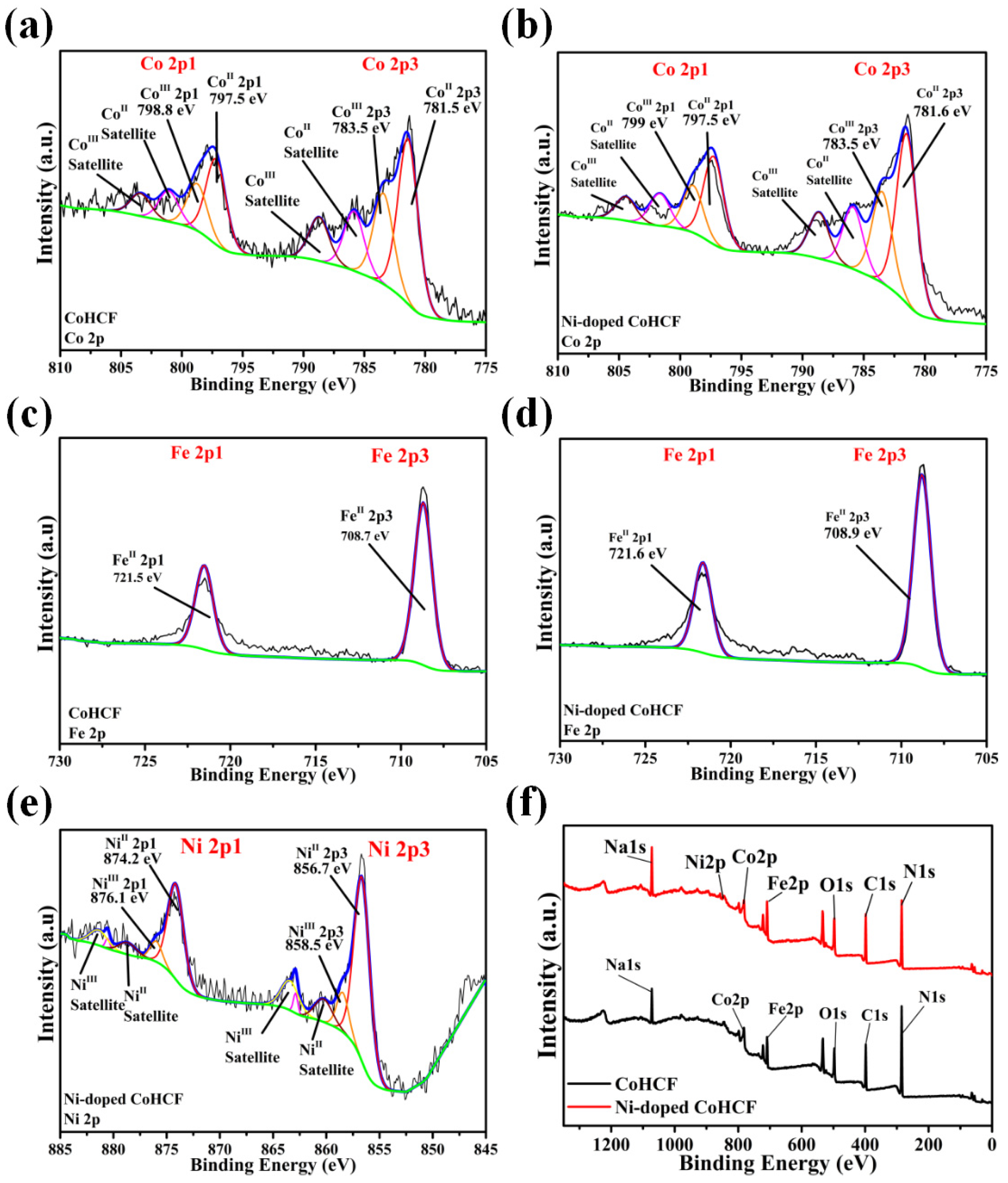
3.1. Structural Characterization of CoHCF and Ni-Doped CoHCF

XRD was used to characterize the phase of the two CoHCF materials, as shown in Figure 2. It can be seen from the XRD patterns of the two materials that the peaks (220) are split into two crystal faces: (220) and (2-20), indicating that the crystal structure of the two CoHCF is monoclinic and both spatial configurations are P211/n. In the PBAs lattice, when M1 and M2 are both discharged states, the attraction of M1 and M2 to surrounding anions (such as CN) is weakened due to their low valence states. At the same time, the lattice expands at the insertion of metal ions, and the crystal face of (220) splits into two crystal faces; the PBAs in this case are usually monoclinic. When both M1 and M2 are in charged states, the valence states of M1 and M2 rise, the attraction to surrounding anions is strengthened, metal ions in the gap are removed, the lattice shrinks, and the split crystal faces are regrouped into a group of crystal faces and become cubic or tetragonal phases [32]. At the same time, from positions (200) and (400) of the two CoHCF, it can be seen that compared with the undoped CoHCF, the diffraction peak position of CoHCF after adding Ni shifts to the right, indicating that the lattice constant of Ni-doped CoHCF is smaller than that of CoHCF. In order to evaluate the degree of Ni doping, EDS tests were performed on Ni-doped CoHCF using scanning electron microscopy, and the results are shown in Figure 3. It can be seen from the figure that the distribution of cobalt and nickel in Ni-doped CoHCF is relatively uniform, and there is no obvious element segregation. This result proves that Ni is uniformly dissolved in CoHCF.
FTIR tests were carried out to further observe the detailed molecular structure and material composition information of the two CoHCF materials, as shown in Figure 4. For PBAs, the absorption peaks at about 2080 cm−1 and 594 cm−1 in the infrared wavelength band are related to C≡N and its surrounding coordination environment, while the absorption peaks at about 1620 cm−1 and 3430 cm−1 are related to the presence of water molecules in HCF. In normal circumstances, the absorption peak number of the C≡N bond is 2080 cm−1, and the longer the bond length of the C≡N bond, the smaller the corresponding absorption peak number [42]. As can be seen from Figure 4, the C≡N bond infrared absorption peak wave number of the two CoHCFs deviates from the normal value. Compared with CoHCF, the wave number of the C≡N bond of Ni-doped CoHCF is higher, indicating that the length of the C≡N bond of Ni-doped CoHCF is shorter. The results of FTIR are in agreement with those of XRD, which further indicates that Ni doping can inhibit the lattice expansion of CoHCF.
XPS tests were performed to determine the types and valence states of the elements contained in the two CoHCFs. The results are shown in Figure 5. The binding energies of two Fe2p peaks in CoHCF are around 721.5 eV and 708.5 eV, corresponding to Fe2+2p1 and Fe2+2p3, respectively, and the valence states of Fe are both +2 [43]. At the same time, the two Co2p peaks are located near 797.5 eV and 781.5 eV in CoHCF, corresponding to Co2+2p1 and Co2+2p3, respectively. The two binding energy peaks near 798.8 eV and 783.5 eV correspond to Co3+2p1 and Co3+2p3, indicating that there are two kinds of Co with +2 and +3 valencies in Ni-doped CoHCF [44]. The binding energies of two Fe2p peaks in Ni-doped CoHCF are around 721.6 eV and 708.9 eV, corresponding to Fe2+2p1 and Fe2+2p3, respectively, and the valence states of Fe are both +2 [43]. At the same time, two binding energy peaks of Co2p are located near 797.5 eV and 781.6 eV, corresponding to Co2+2p1 and Co2+2p3, respectively. The two binding energy peaks near 799 eV and 783.5 eV correspond to Co3+2p1 and Co3+2p3, indicating that there are two kinds of Co with +2 and +3 valence in Ni-doped CoHCF [38]. Ni-doped CoHCF contains a small amount of Ni, and the binding energy peak at 874.2 eV and 856.7 eV corresponds to Ni2+2p1 and Ni2+2p3, while the binding energy peak at 876.1 eV and 856.7 eV corresponds to Ni3+2p1 and Ni3+2p3, indicating that the valence states of Ni are +2 and +3 [44]. The full spectrum of the two CoHCFCs is shown in Figure 5f, and the types of elements possessed by the two CoHCFCs can be seen from the full spectrum of the two CoHCFCs. Among them, the Ni-doped CoHCF contains two M1 elements Ni and Co, which is consistent with the results of EDS in Figure 3. Based on the analysis of the elemental proportion in XPS, the atomic ratio of Co to Fe in CoHCF is 13.1:11, while in Ni-doped CoHCF, the atomic ratio of Co, Ni, and Fe is 11.2:5.5:15.8. Therefore, according to the principle of charge conservation, the chemical formula of CoHCF is Na1.36Co[Fe(CN)6]0.84, and that of Ni-doped CoHCF is Na1.56Co0.67Ni0.33[Fe(CN)6]0.89.

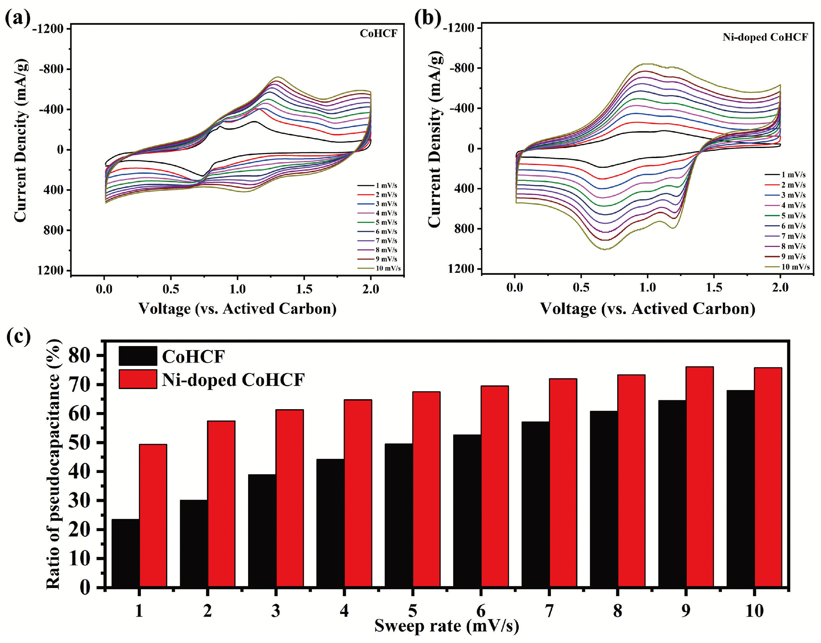
3.2. Electrochemical Properties of CoHCF and Ni-Doped CoHCF

Galvanostatic charge–discharge tests and CV tests were performed to compare the differences in the electrochemical properties of the two CoHCFs. Activated carbon was used as the anode to explore the magnesium storage effect of the two CoHCFs as the cathode materials in a Mg(TFSI)2/AN electrolyte. The results are shown in Figure 6. Figure 6a,b show the voltage-specific capacity diagrams of the two CoHCFs at different cycles at 50 mA/g. As can be seen from Figure 6a, the specific discharge capacity of CoHCF at the 5th, 10th, and 50th laps is 70 mAh/g, 67 mAh/g, and 46 mAh/g, respectively. At the same time, two charging plateaus appear at around 1.2 V and 0.9 V, and a discharge plateau appears at around 0.75 V, although the discharge platform at a high voltage is very small. It can be seen from Figure 6b that under a current density of 50 mA/g, the corresponding specific discharge capacities of Ni-doped CoHCF at the 5th, 10th, and 50th cycles are 80 mAh/g, 89 mAh/g, and 60 mAh/g, respectively. At the same time, a charging plateau appears at around 1.1 V and 0.75 V, and a discharge plateau appears at around 0.65 V. Figure 6c shows the cyclic charging–discharging diagram of the two CoHCF cycles of 90 cycles at a rate of 50 mA/g. From the data of 90 cycles of charging and discharging at a rate of 50 mA/g, it can be seen that the highest specific discharge capacity of Ni-doped CoHCF reaches 89 mAh/g, and the specific discharge capacity of the two CoHCFs gradually decreases with an increase in the number of cycles. Figure 6d shows the magnification performance curves of the two CoHCF under different current densities (50 mA/g, 100 mA/g, 200 mA/g, 100 mA/g, 50 mA/g). The discharge capacity of CoHCF from 50 mA/g to 100 mA/g to 200 mA/g decreases by 26% and 47%, respectively. For Ni-doped CoHCF, the discharge capacity decreases by 16% and 29% from 50 mA/g to 100 mA/g to 200 mA/g, respectively. Figure 6e shows the charge and discharge cycle curves of the two CoHCF cycles for 500 times at a rate of 500 mA/g. It can be seen from the figure that the initial specific discharge capacity of CoHCF is 17 mAh/g, and after 500 cycles, the remaining capacity of CoHCF is 10 mAh/g. The initial specific discharge capacity of Ni-doped CoHCF is 47 mAh/g, and the remaining capacity after 500 cycles is 28 mAh/g. By comparing the two CoHCFs, it can be seen that the rate performance of CoHCF can be improved by the Ni-doping method. Figure 6f shows the CV curves of the two CoHCFs at a sweep speed of 0.2 mV/s. As can be seen from Figure 6f, the CV curve of CoHCF shows two oxidation peaks at 0.91 V vs. AC and 1.2 V vs. AC, and a reduction peak at 0.72 V vs. AC. The CV curve of Ni-doped CoHCF shows an oxidation peak at 0.8 V vs. AC and a reduction peak at 0.68 V vs. AC. The position of the oxidation peak and reduction peak basically corresponds to the charging–discharging plateau of the charging–discharging curve in Figure 6a. It can be seen from the charging–discharging test results of two kinds of CoHCF that the Ni-doping method yields a good improvement on the comprehensive electrochemical performance of CoHCF. Based on the previous analysis of XPS, when the two types of CoHCF reach the maximum discharge specific capacity, the discharge equations of the two types of CoHCF can be expressed as follows:
CoHCF:
Co Fe ( CN ) 6 0.84 + 0.25 Mg 2 + + 0.5 e Mg 0.25 Co Fe ( CN ) 6 0.84
Ni-doped CoHCF:
Co 0.67 Ni 0.33 Fe ( CN ) 6 0.89 + 0.3 Mg 2 + + 0.6 e Mg 0.3 Co 0.67 Ni 0.33 Fe ( CN ) 6 0.89
In order to evaluate the dynamic process of the two CoHCFs during charge and discharge, CV tests at different sweeping rates were performed on the two CoHCFs, and the results are shown in Figure 7. It can be seen from Figure 7a,b that the peak current of the two CoHCFs gradually increases with an increase in the sweep speed from 1 mV/s to 10 mV/s. By separating the capacitance component from the total current response of the REDOX process, the contribution of the capacitance to the total capacity can be quantitatively calculated at different scan rates using the following formula:
i = k 1 v + k 2 v 1 / 2
where k 1 v is the contribution part of pseudocapacitance (electrode reaction), and k 2 v 1 / 2 is the contribution part of diffusion control. Divide both ends of the above equation by v 1 / 2 to obtain the following formula:
i / v 1 / 2 = k 1 v 1 / 2 + k 2
Equation (2) can be viewed as a linear function of i / v 1 / 2 and v 1 / 2 , and the values of k 1 and k 2 can be obtained by linear fitting. The summary results of the capacity contribution of the two CoHCF positive-electrode materials are shown in Figure 7c. It can be seen from Figure 7c that the contribution ratio of the pseudocapacitance of the two CoHCFs gradually increases with an increase in the sweeping rate, but the proportion of the pseudocapacitance of Ni-doped CoHCF is larger than that of CoHCF. It can be seen from the CV curves of the two materials at different sweep rates that Ni doping is beneficial to the ion diffusion process of CoHCF during charging and discharging, and it promotes the electrode reaction.
To compare the structural changes in the two CoHCFs during charging and discharging, the two CoHCFs were tested by ex-situ XRD, and the results are shown in Figure 8. The peak at 18.23° in the figure is the diffraction peak of the binder PVDF. In the ex-situ XRD test, the diffraction peak changes of CoHCF at 17–19° and 34–37° were characterized, and the results are shown in Figure 8a. After a charging–discharging cycle, the peak of CoHCF at about 17.3° (that is, the diffraction peak corresponding to the (200) crystal plane) can not return to the original position, and the diffraction peak at (400) also exhibits the same phenomenon. It can be seen from the above phenomenon that the structure of CoHCF is not stable, resulting in poor magnification and cycle performance. Similarly, changes in the diffraction peaks of Ni-doped CoHCF (200) and (400) were characterized, as shown in Figure 8b. Compared with CoHCF, the diffraction peaks at the beginning and end of Ni-doped CoHCF return to the original position, and the position change amplitude before and after charging and discharging is smaller than that of CoHCF, indicating that Ni improves the structural stability of CoHCF and reduces the lattice change amplitude during Mg2+ (de-)intercalation. It can be seen from the ex-situ XRD test results that Ni doping can improve the lattice stability of CoHCF and the degree of structural change during the charge–discharge process, so as to improve the rate performance and cycle stability of CoHCF during the charge–discharge cycle.
To investigate the changes in the transition metal valence states of the two types of CoHCF during the charging process, ex-situ XPS tests were performed on both types of CoHCF. The results are presented in Figure 9 and Figure 10. As shown in Figure 9a, when the voltage increases to 1.0 V, the Co element in CoHCF undergoes oxidation first, whereas the majority of Co in Ni-doped CoHCF remains in the +2 oxidation state. These findings suggest that the REDOX sites of metallic Co in Ni-doped CoHCF exhibit a delayed response. From Figure 9b, it can be observed that at a charge of 0.8 V, the oxidation state of Fe in Ni-doped CoHCF undergoes minor changes. In Figure 10, by analyzing the discharge behavior of Ni in Ni-doped CoHCF during the charging process, it is evident that the oxidation state of Ni does not change significantly throughout the entire process. Due to the fact that Ni does not participate in REDOX reactions, the extent of lattice distortion in CoHCF during the charging and discharging process is mitigated to a certain degree. Based on these results, it can be concluded that Ni does not participate in the reaction in CoHCF but rather serves as the REDOX potential for the transition metal Co. Combining these findings with the preceding charge–discharge curves, it is clear that for CoHCF, the reaction occurring at 0.9 V involves the transformation of a +2 valence Co to a +3 valence Co, while the reaction at 1.2 V involves the transformation of a +2 valence Fe to a +3 valence Fe. For Ni-doped CoHCF, the reaction at 0.75 V corresponds to the transformation of a +2 valence Fe to a +3 valence Fe, and the reaction at 1.1 V corresponds to the transformation of a +2 valence Co to a +3 valence Co. Combining the preceding charge–discharge curves, it can be concluded that for CoHCF, the reaction occurring at 0.75 V is primarily attributed to the capacity provided by the reduction of Co from +3 to +2 oxidation states. In contrast, the reaction observed at 0.65 V in Ni-doped CoHCF is mainly due to the capacity contributed by the reduction of Fe from +3 to +2 oxidation states. Furthermore, an analysis of the charge–discharge curves across multiple cycles reveals that the capacity degradation of both types of CoHCF materials predominantly occurs during the low-voltage discharge phase. Consequently, for CoHCF, the majority of its capacity originates from REDOX reactions at the Co sites. For Ni-doped CoHCF, the primary contribution to its capacity stems from REDOX reactions at the Fe sites. Thus, Ni doping in CoHCF appears to suppress the valence state changes of Co, enabling the overall charge–discharge process to be predominantly governed by Fe.

4. Conclusions

In summary, the performance of CoHCF as a cathode material for magnesium ion batteries was modified by nickel doping in this study. The highest specific discharge capacity of Ni-doped CoHCF was 89 mAh/g at a current density of 50 mA/g. The initial and final discharge capacities of Ni-doped CoHCF were 47 mAh/g and 28 mAh/g, respectively, at a 500 mA/g current density, and the cycle performance and rate performance of the CoHCF were better than those of the traditional one-step precipitation method. The results of the CV and off-site XRD test at different sweep speeds show that the structural stability of Ni-doped CoHCF is higher than that of CoHCF. Ni-doped CoHCF has a smaller lattice change amplitude and higher structural stability during Mg2+ (de-)intercalation. Through ex-situ XPS testing, it was found that the doping of Ni does not provide REDOX sites, but it changes the REDOX potential of Co. To sum up, the main roles of Ni in CoHCF are as follows:
  • Inhibit the lattice expansion of CoHCF;
  • Enhance the diffusion capacity of magnesium ions in CoHCF;
  • Increase the REDOX potential of Co in CoHCF.

Author Contributions

Conceptualization, F.P.; Methodology, J.W. (Jingfeng Wang); Investigation and formal analysis, P.Z.; Data curation, J.W. (Jiaxu Wang); Writing—original draft preparation, P.Z.; Writing—review and editing, J.W. (Jinxing Wang); project administration, G.H., J.W. (Jingfeng Wang), and F.P. All authors have read and agreed to the published version of the manuscript.

Funding

This research was funded by the Chongqing Technology Innovation and Application Development Project (No. CSTB2022TIAD-KPX0028) and the National Key Research and Development Program of China (No. 2023YFB3809500).

Data Availability Statement

The original contributions presented in this study are included in the article. Further inquiries can be directed to the corresponding authors.

Acknowledgments

The authors express gratitude to the Electron Microscopy Center of Chongqing University and the Analytical Testing Center of Chongqing University for providing equipment support for material characterization in this study.

Conflicts of Interest

The authors declare no conflicts of interest.

References

  1. Gregory, T.D.; Hoffman, R.J.; Winterton, R.C. Nonaqueous electrochemistry of magnesium—Applications to energy-storage. J. Electrochem. Soc. 1990, 137, 775–780. [Google Scholar] [CrossRef]
  2. Aurbach, D.; Lu, Z.; Schechter, A.; Gofer, Y.; Gizbar, H.; Turgeman, R.; Cohen, Y.; Moshkovich, M.; Levi, E. Prototype systems for rechargeable magnesium batteries. Nature 2000, 407, 724–727. [Google Scholar] [CrossRef]
  3. Lu, Z.; Schechter, A.; Moshkovich, M.; Aurbach, D. On the electrochemical behavior of magnesium electrodes in polar aprotic electrolyte solutions. J. Electroanal. Chem. 1999, 466, 203–217. [Google Scholar] [CrossRef]
  4. Zhang, Y.; Geng, H.; Wei, W.; Ma, J.; Chen, L.; Li, C.C. Challenges and recent progress in the design of advanced electrode materials for rechargeable Mg batteries. Energy Storage Mater. 2019, 20, 118–138. [Google Scholar] [CrossRef]
  5. Zhang, M.; Feng, S.; Wu, Y.; Li, Y. Cathode Materials for Rechargeable Magnesium-Ion Batteries: A Review. Energy Storage Mater. 2023, 39, 2205050. [Google Scholar] [CrossRef]
  6. Mizanuzzaman, M.; Chowdhury, M.A.; Khandaker, T.; Islam, M.S.; Kowser, M.A.; Islam, M.M. Advancements in cathode materials for high-performance rechargeable magnesium-ion batteries. J. Energy Storage 2025, 118, 116213. [Google Scholar] [CrossRef]
  7. Guo, W.; Hanaor, D.A.H.; Kober, D.; Wang, J.; Bekheet, M.F.; Gurlo, A. Rechargeable Magnesium Ion Batteries Based on Nanostructured Tungsten Disulfide Cathodes. Batteries 2022, 8, 116. [Google Scholar] [CrossRef]
  8. Caggiu, L.; Enzo, S.; Stievano, L.; Berthelot, R.; Gerbaldi, C.; Falco, M.; Garroni, S.; Mulas, G. Solvent-Free Mechanochemical Approach towards Thiospinel MgCr2S4 as a Potential Electrode for Post-Lithium Ion Batteries. Batteries 2020, 6, 43. [Google Scholar] [CrossRef]
  9. Sun, X.; Bonnick, P.; Nazar, L.F. Layered TiS2 Positive Electrode for Mg Batteries. ACS Energy Lett. 2016, 1, 297–301. [Google Scholar] [CrossRef]
  10. Yang, J.; Wang, J.; Zhu, L.; Wang, X.; Dong, X.; Zeng, W.; Wang, J.; Pan, F. Enhancing Mg2+ and Mg2+/Li+ Storage by Introducing Active Defect Sites and Edge Surfaces in MoSe2. ChemElectroChem 2021, 8, 4252–4260. [Google Scholar] [CrossRef]
  11. Kim, J.-S.; Chang, W.-S.; Kim, R.-H.; Kim, D.-Y.; Han, D.-W.; Lee, K.-H.; Lee, S.-S.; Doo, S.-G. High-capacity nanostructured manganese dioxide cathode for rechargeable magnesium ion batteries. J. Power Sources 2015, 273, 210–215. [Google Scholar] [CrossRef]
  12. Attias, R.; Salama, M.; Hirsch, B.; Pant, R.; Gofer, Y.; Aurbach, D. Anion Effects on Cathode Electrochemical Activity in Rechargeable Magnesium Batteries: A Case Study of V2O5. ACS Energy Lett. 2018, 4, 209–214. [Google Scholar] [CrossRef]
  13. Nguyen, D.-T.; Prabhakaran, V.; Kovarik, L.; Alexander, G.; Cabana, J.; Connell, J.G.; Hu, J.Z.; Shutthanandan, V.; Sivakumar, B.M.; Mueller, K.T.; et al. Structural and chemical evolutions of a magnesium vanadium oxide cathode under electrochemical cycling in magnesium batteries. Nano Energy 2024, 128, 109939. [Google Scholar] [CrossRef]
  14. Kwon, N.H.; Lee, K.-G.; Kim, H.K.; Hwang, S.-J. MnO2-based nanostructured materials for various energy applications. Mater. Chem. Front. 2021, 5, 3549–3575. [Google Scholar] [CrossRef]
  15. Li, X.; Suo, C.; Zhang, B.; Hu, B.; Huang, J.; Zhao, Y.; Zhang, W.; Ji, X.; Li, W. Free water based high capacity aqueous magnesium ion battery with nano-amorphized cathodic V6O13@Mg-MnO2 in the presence of Cl. Chem. Eng. J. 2025, 510, 161725. [Google Scholar] [CrossRef]
  16. Perez-Vicente, C.; Rubio, S.; Ruiz, R.; Zuo, W.; Liang, Z.; Yang, Y.; Ortiz, G.F. Olivine-Type MgMn0.5Zn0.5SiO4 Cathode for Mg-Batteries: Experimental Studies and First Principles Calculations. Small 2023, 19, e2206010. [Google Scholar] [CrossRef]
  17. Torres, A.; Arroyo-de Dompablo, M.E. Comparative Investigation of MgMnSiO4 and Olivine-Type MgMnSiS4 as Cathode Materials for Mg Batteries. J. Phys. Chem. C 2018, 122, 9356–9362. [Google Scholar] [CrossRef]
  18. Romio, M.; Surace, Y.; Mautner, A.; Hamid, R.; Jahn, M.; Cupid, D.M.; Abrahams, I. A Comparative Mechanistic Study on the Intercalation Reactions of Mg2+ and Li+ Ions into (Mg0.5Ni0.5)3(PO4)2. Batteries 2023, 9, 342. [Google Scholar] [CrossRef]
  19. Mustafa, M.; Rani, M.S.A.; Adnan, S.B.R.S.; Salleh, F.M.; Mohamed, N.S. Characteristics of new Mg0.5(Zr1-xSnx)2(PO4)3 NASICON structured compound as solid electrolytes. Ceram. Int. 2020, 46, 28145–28155. [Google Scholar] [CrossRef]
  20. Mizuno, Y.; Okubo, M.; Hosono, E.; Kudo, T.; Oh-ishi, K.; Okazawa, A.; Kojima, N.; Kurono, R.; Nishimura, S.-i.; Yamada, A. Electrochemical Mg2+ intercalation into a bimetallic CuFe Prussian blue analog in aqueous electrolytes. J. Mater. Chem. A 2013, 1, 13055–13059. [Google Scholar] [CrossRef]
  21. Lipson, A.L.; Han, S.-D.; Kim, S.; Pan, B.; Sa, N.; Liao, C.; Fister, T.T.; Burrell, A.K.; Vaughey, J.T.; Ingram, B.J. Nickel hexacyanoferrate, a versatile intercalation host for divalent ions from nonaqueous electrolytes. J. Power Sources 2016, 325, 646–652. [Google Scholar] [CrossRef]
  22. Zhang, H.; Yu, Y.; Zhang, L.; Zhai, Y.; Dong, S. Self-powered fluorescence display devices based on a fast self-charging/recharging battery (Mg/Prussian blue). Chem. Sci. 2016, 7, 6721–6727. [Google Scholar] [CrossRef] [PubMed]
  23. Chae, M.S.; Hyoung, J.; Jang, M.; Lee, H.; Hong, S.-T. Potassium nickel hexacyanoferrate as a high-voltage cathode material for nonaqueous magnesium-ion batteries. J. Power Sources 2017, 363, 269–276. [Google Scholar] [CrossRef]
  24. Marzak, P.; Kosiahn, M.; Yun, J.; Bandarenka, A.S. Intercalation of Mg2+ into electrodeposited Prussian Blue Analogue thin films from aqueous electrolytes. Electrochim. Acta 2019, 307, 157–163. [Google Scholar] [CrossRef]
  25. Shrivastava, A.; Liu, S.; Smith, K.C. Linking capacity loss and retention of nickel hexacyanoferrate to a two-site intercalation mechanism for aqueous Mg2+ and Ca2+ ions. Phys. Chem. Chem. Phys. 2019, 21, 20177–20188. [Google Scholar] [CrossRef]
  26. Kuperman, N.; Cairns, A.; Goncher, G.; Solanki, R. Structural water enhanced intercalation of magnesium ions in copper hexacyanoferrate nonaqueous batteries. Electrochim. Acta 2020, 362, 137077. [Google Scholar] [CrossRef]
  27. Huang, K.; Qu, B.; Shen, X.; Deng, R.; Li, R.; Huang, G.; Tang, A.; Li, Q.; Wang, J.; Pan, F. A Novel Asymmetric Diffusion Path for Superior Ion Dynamic in High-Voltage Mg-Based Hybrid Batteries. Adv. Sci. 2024, 11, e2406451. [Google Scholar] [CrossRef]
  28. Ling, C.; Chen, J.J.; Mizuno, F. First-Principles Study of Alkali and Alkaline Earth Ion Intercalation in Iron Hexacyanoferrate: The Important Role of Ionic Radius. J. Phys. Chem. C 2013, 117, 21158–21165. [Google Scholar] [CrossRef]
  29. Chen, J.; Wei, L.; Mahmood, A.; Pei, Z.; Zhou, Z.; Chen, X.; Chen, Y. Prussian blue, its analogues and their derived materials for electrochemical energy storage and conversion. Energy Storage Mater. 2020, 25, 585–612. [Google Scholar] [CrossRef]
  30. Muneer, W.; Khan, M.I.; Shah, S.K.; Ullah, A.; Iqbal, J.; Khan, M.A. Advances in prussian blue analogues: A comprehensive review on synthesis methods and battery applications. Mater. Chem. Phys. 2025, 332, 16. [Google Scholar] [CrossRef]
  31. Jiang, M.; Hou, Z.; Ren, L.; Zhang, Y.; Wang, J.-G. Prussian blue and its analogues for aqueous energy storage: From fundamentals to advanced devices. Energy Storage Mater. 2022, 50, 618–640. [Google Scholar] [CrossRef]
  32. Wang, B.; Han, Y.; Wang, X.; Bahlawane, N.; Pan, H.; Yan, M.; Jiang, Y. Prussian Blue Analogs for Rechargeable Batteries. iScience 2018, 3, 110–133. [Google Scholar] [CrossRef] [PubMed]
  33. Bie, X.; Kubota, K.; Hosaka, T.; Chihara, K.; Komaba, S. Synthesis and electrochemical properties of Na-rich Prussian blue analogues containing Mn, Fe, Co, and Fe for Na-ion batteries. J. Power Sources 2018, 378, 322–330. [Google Scholar] [CrossRef]
  34. Ge, P.; Li, S.; Shuai, H.; Xu, W.; Tian, Y.; Yang, L.; Zou, G.; Hou, H.; Ji, X. Ultrafast Sodium Full Batteries Derived from X-Fe (X = Co, Ni, Mn) Prussian Blue Analogs. Adv. Mater. 2019, 31, e1806092. [Google Scholar] [CrossRef]
  35. Xu, Y.; Wan, J.; Huang, L.; Ou, M.; Fan, C.; Wei, P.; Peng, J.; Liu, Y.; Qiu, Y.; Sun, X.; et al. Structure Distortion Induced Monoclinic Nickel Hexacyanoferrate as High-Performance Cathode for Na-Ion Batteries. Adv. Energy Mater. 2018, 9, 1803158. [Google Scholar] [CrossRef]
  36. Yan, C.; Zhao, A.; Zhong, F.; Feng, X.; Chen, W.; Qian, J.; Ai, X.; Yang, H.; Cao, Y. A low-defect and Na-enriched Prussian blue lattice with ultralong cycle life for sodium-ion battery cathode. Electrochim. Acta 2020, 332, 135533. [Google Scholar] [CrossRef]
  37. Yu, W.; Wang, K.; Xu, R.; Wu, M.; Liu, C.; Su, X. Sodium-Rich Prussian Blue Analogs Synthesized with Reducing Sodium Salt for Enhanced Rate and Cycling Stability Sodium-Ion Storage. ACS Appl. Mater. Interfaces 2025, 17, 7870–7880. [Google Scholar] [CrossRef]
  38. Ma, X.-H.; Wei, Y.-Y.; Zhou, J.-F.; Zhou, J.-H.; Zhao, S.-W.; Jia, W.; Dai, J.-M.; Zi, Z.-F. Low-defect Na2Co[Fe(CN)6] synthesized by a facile electrostatic spray assisted coprecipitation method as cathode for sodium-ion batteries. Electrochim. Acta 2018, 272, 44–51. [Google Scholar] [CrossRef]
  39. Liu, H.; Zhang, J.; Zhang, X.; Li, J.; Liu, Y.; Cai, X.; Li, W.; Yu, H.; Yan, L.; Zhang, L.; et al. Cobalt hexacyanoferrate enhanced by common ion effect for aqueous potassium-ion batteries. Appl. Surf. Sci. 2022, 604, 154654. [Google Scholar] [CrossRef]
  40. Pan, Z.T.; He, Z.H.; Hou, J.F.; Kong, L.B. Designing CoHCF@FeHCF Core-Shell Structures to Enhance the Rate Performance and Cycling Stability of Sodium-Ion Batteries. Small 2023, 19, e2302788. [Google Scholar] [CrossRef]
  41. Ren, L.; Wang, J.-G.; Liu, H.; Shao, M.; Wei, B. Metal-organic-framework-derived hollow polyhedrons of prussian blue analogues for high power grid-scale energy storage. Electrochim. Acta 2019, 321, 134671. [Google Scholar] [CrossRef]
  42. Xia, L.; McCreery, R.L. Structure and function of ferricyanide in the formation of chromate conversion coatings on aluminum aircraft alloy. J. Electrochem. Soc. 1999, 146, 3696–3701. [Google Scholar] [CrossRef]
  43. Xu, P.; Wang, G.; Wang, H.; Li, Y.; Miao, C.; Qu, J.; Zhang, Y.; Ren, F.; Cheng, K.; Ye, K.; et al. K2.25Ni0.55Co0.37Fe(CN)6 nanoparticle connected by cross-linked carbon nanotubes conductive skeletons for high-performance energy storage. Chem. Eng. J. 2017, 328, 834–843. [Google Scholar] [CrossRef]
  44. Jing, M.; Long, K.; Liu, R.; Wang, X.; Wu, T.; Zhu, Y.; Liu, L.; Zhang, S.; Zhang, Y.; Liu, C. One-Step Hydrothermally Synthesized Ni11(HPO3)8(OH)6/Co3(HPO4)2(OH)2 Heterostructure with Enhanced Rate Performance for Hybrid Supercapacitor Applications. Batteries 2024, 10, 339. [Google Scholar] [CrossRef]
Figure 1. Structural model of Prussian Blue Analogs (PBAs).
Batteries 11 00213 g001
Figure 2. XRD patterns of CoHCF and Ni-doped CoHCF. (a) Total images, (b) local region of 16–18 and 34–36 degrees.
Batteries 11 00213 g002
Figure 3. SEM and EDS result of Ni-doped CoHCF.
Batteries 11 00213 g003
Figure 4. FTIR spectra of CoHCF and Ni-doped CoHCF.
Batteries 11 00213 g004
Figure 5. (a,c) XPS spectra of CoHCF Fe2p and Co2p, relatively. (b,d,e) XPS spectra of Ni-doped CoHCF Fe2p, Co2p, and Ni2p, relatively. (f) XPS spectra of CoHCF and Ni-doped CoHCF.
Batteries 11 00213 g005
Figure 6. Charge/discharge curves for (a) CoHCF, (b) Ni-doped CoHCF at 50 mA/g in different circles; (c) specific capacity and coulombic efficiency of CoHCF and Ni-doped CoHCF at 50 mA/g for 90 circles; (d) specific capacity of CoHCF and Ni-doped CoHCF at 500 mA/g for 500 circles; (e) specific capacity of Ni-doped CoHCF at different current densities; (f) CV curves of CoHCF and Ni-doped CoHCF at 0.2 mV/s.
Batteries 11 00213 g006
Figure 7. (a,b) CV curves of two CoHCFs at different sweeping rates (1–10 mV/s). (c) Contribution rate of pseudocapacitance of two materials at different sweep rates.
Batteries 11 00213 g007
Figure 8. XRD patterns of CoHCF (a) and Ni-doped CoHCF (b) during charging and discharging process.
Batteries 11 00213 g008
Figure 9. XPS spectra of (a) Co2p, (b) Fe2p in two CoHCFs during charging process.
Batteries 11 00213 g009
Figure 10. XPS spectra of Ni2p in Ni-doped CoHCF during charging process.
Batteries 11 00213 g010
Disclaimer/Publisher’s Note: The statements, opinions and data contained in all publications are solely those of the individual author(s) and contributor(s) and not of MDPI and/or the editor(s). MDPI and/or the editor(s) disclaim responsibility for any injury to people or property resulting from any ideas, methods, instructions or products referred to in the content.

