1. Introduction
Li-ion batteries (LIBs) are the dominant energy storage technology for electric vehicles due to their role in reducing CO2 emissions, enhancing energy efficiency, and delivering high rechargeability. Beyond the automotive sector, LIBs have found extensive applications in mobile electronics, grid-scale energy storage, and other applications. Among the advanced energy storage devices, LIBs are one of the most widely used solutions, thanks to their high specific power, low self-discharge, wide operating temperature range, resistance to the memory effect, environmental friendliness, and long cycle stability.
Yet, despite their widespread use, commercial LIBs have certain significant limitations, particularly in terms of safety and energy density. LIBs are typically founded on liquid electrolytes that are composed of high ionic conductivity organic solvents. The solvents are, however, naturally volatile, flammable, and toxic, hence constituting significant safety and environmental risks, including leakage, fire hazard, explosion, short circuits, and lithium dendrite growth, all of which are hazards to human health and environmental safety [
1,
2,
3].
In addition, the energy density of the current top LIBs is still a restriction. Currently, the systems boast gravimetric energy densities between 210 and 235 Wh·kg
−1 and volumetric energy densities of 400–630 Wh·L
−1. In order to facilitate greater electrification of next-generation applications, there will have to be a significant leap in both gravimetric and volumetric energy densities [
4,
5].
In order to overcome the above limitations, many research efforts have been directed towards the development of advanced materials for LIB components, i.e., anodes, cathodes, and electrolytes [
6]. The most promising route has been replacing conventional liquid or gel electrolytes with all-solid-state electrolytes. Solid-state batteries (ASSBs) are considered more desirable than traditional LIBs, with increased energy density, improved thermo-mechanical and electrochemical stability, and inherently lower flammability—characteristics that help us to design more compact, strong, and safe battery systems [
7,
8,
9,
10].
However, the commercialization of ASSBs is broad, primarily due to their relatively low ionic conductivity. For instance, solid polymer electrolytes (SPEs) possess ionic conductivities of the order of 10
−5 S·cm
−1 at room temperature, which is approximately two to three orders lower than those in conventional liquid electrolytes (~10
−2 S/cm) [
11].
At present, tremendous research efforts on solid-state battery development are being undertaken and the state of the art is continuously under development. This paper provides a critical review of solid-state batteries, with the aim of creating an actual review of the state of the art of different relevant aspects of solid-state battery development and their possible applications. The work reviews the different possible chemistries based on the different electrolyte composition possibilities. Also, the different options for solid-state battery production techniques are reviewed. Further, the work highlights different aspects of the battery management system (BMS), such as the different BMS types that can operate a solid-state battery, as well as methods for SoC determination and cell balancing. Also, the thermal management system for different types of solid-state batteries is reviewed, as well as a critical review and analysis of the environmental performance of different types of solid-state batteries. Lastly, the work reviews the applicability of solid-state batteries in different possible application areas, such as (heavy and light duty) EVs, consumer electronics, aerospace and defense, and renewable energy storage.
2. Chemistry
Solid-state batteries (SSBs) employ solid electrolytes in place of the liquid- or gel-type electrolytes used traditionally in Li-ion batteries. The solid electrolytes have improved thermal and chemical stability, hence eliminating safety concerns which are normally associated with liquid electrolytes, including flammability and thermal degradation. Moreover, the SSB structural layout deviates substantially from that of Li-ion batteries, where a single solid electrolyte layer serves as both the separator and electrolyte, in contrast to the discrete separator between the cathode and anode in traditional LIB configurations [
12]. It may, at first glance, appear contradictory that ionic conductivity is both beneficial and deleterious in the case of SSBs. This apparent paradox results from the material-dependent nature of solid-state electrolytes. Certain types of solid electrolytes, particularly sulfide-based systems, have high ionic conductivities (≥10
−3 S·cm
−1) comparable with liquid electrolytes and hence qualify as promising materials for high-performance SSBs. Oxide- and polymer-based electrolytes, however, tend to have much lower ionic conductivities, typically between 10
−5 to 10
−7 S·cm
−1, at ambient temperature. This limited ionic mobility can impair battery performance, most significantly under low-temperature operating conditions or at high charge/discharge rates (C-rates). Thus, solid-state electrolyte ionic conductivity is a material-dependent quantity with both a controlling advantage and a primary challenge in SSB design. This paradox underscores the determinative importance of electrolyte selection in maximizing solid-state battery technologies (
Figure 1).
Li-ion batteries have been known to offer a range of advantageous properties, including long cycle life, high power density, low self-discharge rates, and high gravimetric and volumetric energy densities. However, these systems are confronted with several challenges, such as the unavailability of crucial raw materials, inherent safety risks involved in using flammable solvents, and constraints on increasing energy storage capacity further. Much of the issues with conventional Li-ion batteries stem from the liquid electrolytes employed in their design. Organic solvents in such electrolytes are flammable and pose severe safety concerns, and side reactions between the conductive salt and other elements cause capacity degradation and long-term battery aging. In contrast, all-solid-state batteries (ASSBs) inherently possess superior safety profiles since they entirely remove flammable organic materials from their design (
Table 1). In addition, ASSBs provide bright prospects for surpassing the limits of current technologies in terms of energy density. Compared with conventional LIBs, relying on a liquid electrolyte-soaked porous separator, ASSBs employ a solid electrolyte that functions as both an electrical insulator and an ionic conductor at the same time (
Figure 2). This solid-state architecture is not only an added advantage in that it can be used as a robust physical barrier for the penetration of lithium dendrites, but it also allows for the safe use of lithium metal as an anode material. The employment of such an architecture not only enhances the safety of the battery system significantly but also holds substantial promise for the realization of next-generation energy storage technologies [
13].
When starting a car equipped with a Li-ion battery, turning it on completes the circuit in which the battery operates. This initiates the movement of positively charged lithium ions through the liquid electrolyte and separator from the anode to the cathode. This process triggers chemical reactions that produce electrons, which flow in the opposite direction through the external circuit, generating the electrical current that powers the car. During charging, this process reverses, with the ions and current moving in the opposite direction. In contrast, solid-state batteries feature a solid lithium metal anode and a solid ceramic electrolyte, which also serves as the separator. In this design, the separator integrates into the solid medium through which lithium ions migrate. During charging, the lithium ions form a solid layer on the anode. This results in a smaller volume compared to the anode in a traditional Li-ion battery, enabling higher energy density in a smaller battery footprint (
Figure 3) [
14]. Solid-state batteries offer a compelling alternative to conventional Li-ion batteries for several reasons: The solid electrolyte potentially eliminates the need for a separator, occupying less space than a liquid electrolyte, thereby enabling smaller battery designs compared to traditional Li-ion batteries. Recent advancements suggest potential applications in short-haul aircraft and heavy trucks. Lithium, being the lightest metal element, contributes to solid-state batteries’ lighter weight compared to EVs powered by conventional batteries. This advantage allows for higher energy density in a smaller package, addressing the increasing weight of EVs and reducing pollution from sources such as tire particulates. Unlike Li-ion batteries, which use volatile, flammable liquid electrolytes prone to causing fires, solid-state batteries exhibit higher thermal stability and can withstand higher temperatures, enhancing safety. The smaller size and increased energy density of solid-state batteries mean they can potentially increase vehicle range, with some manufacturers claiming up to 745 miles on a single charge. Charging times for solid-state batteries could be significantly reduced, potentially reaching 80% charge in as little as 10 or 15 min, compared to the 20 min to 12 hours typically required for Li-ion batteries in EVs. Additionally, solid-state batteries can endure approximately five times more charge cycles over their lifespan, thereby increasing longevity. Furthermore, solid-state batteries typically have a lower carbon footprint due to the reduced use of materials, potentially reducing climate impact by up to 39% compared to Li-ion batteries [
14].
Finding a solid material with sufficient conductivity for large batteries, whether polymer or ceramic (requiring high ionic conductivity in solid electrolytes), is crucial. Superionic materials are utilized to achieve this conductivity, allowing ions to move swiftly through their crystal structure, making them suitable for solid electrolyte creation. However, their ionic conductivity is typically low, hindering rapid charge and discharge rates. Establishing a stable conductive interface between the solid electrolyte and electrode poses a significant challenge. High resistance at the solid electrolyte–electrode interface results in low power output. Additionally, poor electronic conductivity can lead to damage from electron beam radiation. Research into solid electrolytes is expanding primarily due to safety concerns. The future of solid-state batteries holds promises for replacing current commercial Li-ion batteries, which rely on liquid electrolytes. Solid-state batteries are envisioned to be highly safe and efficient due to their high ionic conductivity and elevated melting points. Integrating solid-state batteries into electric vehicles could eliminate cooling components, reducing battery pack weight and enabling vehicles to achieve longer ranges with smaller battery sizes. While solid-state battery technology is not yet commercially available, its potential for replacing current Li-ion batteries is promising (
Table 1) [
13].
LiPF6 salt, or lithium hexafluorophosphate salt, is the most often used base salt for creating the electrolyte in Li-ion batteries, while other base salts that are typically inorganic can also be employed. LiBF4 (lithium tetrafluoroborate) and LiClO4 (lithium perchlorate) are two more commonly used salts. Several organic solvents, including EC (ethylene carbonate), DEC (diethyl carbonate), EMC (ethyl–methyl carbonate), DMC (dimethyl carbonate), and PC (propylene carbonate), are dissolved with one of these salts. Every solvent has a unique set of benefits, including the ability to function at low and high temperatures as well as how it impacts the degradation of battery capacity (which occurs as a side reaction with the electrodes). Therefore, to fully utilize the benefits of each solvent, these solvents are combined in the appropriate ratio.
Solid-state batteries are known for their exceptional temperature stability and the reduced need for extensive thermal management. Their fireproof nature, attributed to the solid-state electrolyte, also inhibits dendrite growth, mitigating the risk of short circuits [
11]. Moreover, the development of cathode materials with high ionic conductivity, electrochemical stability, thermal resilience, and enhanced mechanical properties holds promise for solid-state batteries. It is worth noting that there are various types of solid-state batteries, distinguished by their electrolyte composition.
On the other hand, while solid-state batteries (SSBs) offer significant safety and energy density advantages, their long-term performance and reliability are strongly influenced by unique degradation mechanisms that differ from those in conventional Li-ion systems. One of the most critical challenges is the formation of interfacial resistance between the solid electrolyte and electrode materials. Poor interfacial contact, especially during cycling, can lead to increased impedance, mechanical delamination, and eventual cell failure. This is often exacerbated by volume changes in electrode materials, particularly lithium metal and silicon-based anodes.
Another major issue is the growth of lithium filaments or dendrites, which can penetrate the solid electrolyte—even those considered “dendrite-resistant”—under high current densities or uneven pressures. These filaments can cause internal short circuits and rapid capacity loss.
Mechanical degradation is also a major concern. Many inorganic electrolytes, such as oxide ceramics, are brittle and prone to cracking under thermal or mechanical stress. Such cracks can serve as pathways for dendrites or disrupt ionic conduction. In contrast, while sulfide-based electrolytes are softer and more compliant, they are chemically unstable in air and require encapsulation to prevent degradation from moisture or oxygen exposure.
Lastly, electrochemical side reactions at the electrode–electrolyte interfaces—such as oxidation of the solid electrolyte or decomposition due to high-voltage cathodes—can lead to irreversible capacity fading and increased interfacial resistance.
Understanding and mitigating these degradation mechanisms through interface engineering, protective coatings, pressure optimization, and electrolyte design is key to extending SSB cycle life and making them commercially viable.
2.1. Solid Inorganic Electrolyte
Solid inorganic electrolytes (ISEs) are highly promising for a wide range of applications, primarily due to their exceptional safety profile, high ionic conductivity exceeding 10
−3 S·cm
−1 at room temperature, efficient Li-ion transfer capabilities, and resistance to fire hazards [
15]. The structure of solid inorganic electrolytes typically comprises two sets of lattices: a solid crystal consisting of skeletal ions and a sublattice containing migrating ions. Among solid inorganic electrolytes, oxide- and sulfur-based structures are particularly noteworthy based on their elemental composition. Moreover, there has been significant research interest in borohydride and halide materials in recent years [
4].
2.1.1. Oxide Electrolytes
Solid-state electrolytes, while offering high mechanical and chemical stability, often require high-temperature processing (sintering), are brittle, and exhibit relatively poor ionic conductivity. These characteristics pose challenges such as increased interface resistance, higher manufacturing costs, and lower production efficiency. They can be categorized into two types: perovskite type and amorphous (glassy) oxide type.
The perovskite types of solid-state electrolytes, exemplified by crystal oxides, are significant due to their straightforward preparation process and strong structural stability. These electrolytes, following the general formula BO
3, consist of B region ions (like Ti, Sn, Zr, etc.) and A region ions (such as Na, K, Ca, Ba, etc.). Among them, the Li
3xLa
2/3–xTiO
3 (LLTO) compound, belonging to the cubic crystal system, is extensively studied and regarded as a key representative of perovskite-type solid-state electrolytes [
4]. The synthesis of LLTO typically involves methods such as the solid-phase method, sol–gel method, co-precipitation method, and combustion method [
16,
17,
18]. Despite its high particle conductivity, LLTO faces several challenges during synthesis. The high temperatures involved can lead to difficulties in controlling the final product’s composition, resulting in the loss of Li
2O and hampering the achievement of high conductivity. Moreover, LLTO tends to exhibit high interface resistance. An essential factor influencing ionic conductivity is the precise stoichiometric ratios between Li
+, La
3+, and TiO
32+. Among these, Li
0.3La
0.57TiO
3 has shown the highest lithium-ion conductivity, typically ranging from 10
−4 to 10
−3 S·cm
−1. In a study by Zhang et al. [
19], LLTO was synthesized using the coagulated solution method, which is comparatively cost-effective and straightforward. A sintered LLTO at various temperatures and the observed grain conductivity and overall conductivity was demonstrated as detailed in
Table 2 [
19].
In the study conducted by Mei et al., it was observed that the grain conductivity of LLTO increased with spark plasma sintering temperatures. This increase signifies the formation of pure LLTO, indicating improved conductivity with larger grain sizes Specifically, the study found a grain conductivity of 10
-4 S·cm
−1 for single-crystalline grains and 10
−5 S·cm
−1 for bulk materials [
20]. However, Xiong et al. was synthesized using the solid-state method, and LLTO films were produced through reactive DC magnetron sputtering. The magnetron sputtering method offers advantages such as high efficiency, controllable thickness, and good substrate adhesion. The effects of different treatments on the morphology, structure, and photoelectric properties of the prepared films were investigated. Films treated at temperatures exceeding 400 °C exhibited deteriorated morphology. The ionic conductivity of films treated at 300 °C was determined to be 5 × 10
−5 S·cm
−1 [
21].
Additionally, various other perovskite-type electrolytes, including LaAlO
3-SrTiO
3 (LAST) [
22], Lanthanum Gallate (LaGaO
3, LG) [
23], Lanthanum Strontium Gallate (La
0.9Sr
0.1Ga
0.8Mg
0.2O
3−δ, LSGM) [
24], Lanthanum Strontium Manganite (La
0.6Sr
0.4MnO
3−δ, LSM) [
25], Lanthanum Strontium Cobaltite (La
0.6Sr
0.4CoO
3−δ, LSC) [
23], Barium Cerate (BaCe
0.8Y
0.2O
3−δ, BCTY) [
26], and strontium titanate (SrTiO
3, STO) [
27], are being explored as potential solid-state electrolytes.
Garnet-type solid-state electrolytes (SSEs) are notable for their crystalline oxide structure, which offers high ionic conductivity and chemical stability towards lithium metal, along with a broad operating temperature range [
28]. The general formula for garnet electrolytes is Li
3+xA
3B
2O
12. LLZO (Li
7La
3Zr
2O
12) stands out as one of the most promising garnet-type SSEs for commercialization, initially synthesized in 2007 by Murugan et al. via a solid-state reaction, demonstrating good thermal stability [
29]. Current research focuses on variants of LLZO with tetragonal and cubic crystal structures. While cubic LLZO exhibits high conductivity, it is less stable at room temperature. However, stability can be enhanced by substituting Zr
4+ with different cations like Al
3+, Nb
3+, or Ta
5+.
The standard synthesis methods for garnet SSEs include the solid-phase and sol–gel methods. LLZO produced via the solid-phase method typically exhibits high room temperature conductivity, while the sol–gel method yields nano-powders efficiently. Advanced sintering techniques such as the co-precipitation method [
30] and field-assisted sintering technology (FAST) [
31] can further improve the quality of LLZO garnet electrolytes. However, LLZO faces challenges such as Li
2CO
3 pollution, where the formation of a Li
2CO
3 layer deteriorates ionic conductivity [
32].
NASICON-type solid electrolytes are crystalline oxide materials known for their high ionic conductivity and compatibility with Li metal interfaces. Their general formula is AM’M”P
3O
12, where A represents alkali metal ions like Na
+, K
+, or Li
+ and M’ denotes ions such as Ti
4+, Zr
4+, or Ge
4+. Among NASICON-type solid electrolytes, LATP (Li
1+xAl
xTi
2−x(PO
4)
3) and LAGP (Li
1+xAl
xGe
2−x(PO
4)
3) are extensively studied [
33]. NASICON electrolytes can accommodate up to 4 moles of sodium ions per formula unit, with the mass conductivity determined by the concentration and mobility of mobile charge carriers. To achieve Li-ion conductivity, A must be Li
+. The preparation process, including raw material ratios, mixing methods, molding, and sintering technologies, significantly impacts SSE conductivity. The high-temperature solid-phase method typically requires high-temperature sintering to achieve high density in NASICON materials [
10,
34].
Doping titanium and phosphorus with other elements can enhance SSE conductivity. For instance, Al-doped LATP demonstrates outstanding electrochemical performance, with room temperature ionic conductivity reaching up to 1.21 × 10
−3 S·cm
−1 [
35]. However, LATP’s incompatibility with low-potential anodes like lithium limits its use in solid-state lithium batteries [
36]. A potential solution is substituting titanium with germanium to create Li
1+xAl
yGe
2−y(PO
4)
3 LAGP, which mitigates titanium’s rapid reduction in electrochemical environments [
37,
38]. These materials offer broad potential applications due to their availability and performance characteristics.
A Li
3N solid-state electrolytes was among the earliest crystalline oxide solid electrolytes studied [
39]. While single crystals exhibit higher electrical conductivity along specific crystal surfaces, the polycrystalline state experiences reduced conductivity due to Li
3N’s layered structure and poor stability. To address this, LiX (where X = Cl, Br, I) is added to Li
3N to form a solid solution, enhancing durability [
40]. However, the conductivity of this solid solution decreases as its dissociation voltage increases. To further boost ionic conductivity, the Li
3N-LiX material incorporates MI (where M = Li, Na, K), and Na
+ and K
+ ions replace Li
+ in Li
1.8N
0.4Cl
0.6. This substitution results in materials like Li
9−nxM
xN
2Cl
3 (where M = Na, K, Mg, Al, etc.). Despite these efforts, Li
3N-based electrolytes face limited applications in ASSB systems due to their low ionic conductivity and high dissociation voltage [
4].
LiPON (lithium phosphorus oxynitride) solid-state electrolyte is a glass-like oxide material known for its high chemical stability and broad electrochemical properties [
4]. It is compatible with various cathode materials such as LiNi
0.5Mn
1.5O
4, V
2O
5, and LiCoO
2 [
41,
42]. However, its low ionic conductivity has been a challenge. To address this, Bates and his team pioneered the use of LiPON as a thin film electrolyte layer, significantly improving its ionic conductivity. Currently, methods like ion beam sputtering, atomic layer deposition, and sol–gel chemical methods are used to synthesize electrolyte films that meet the requirements of all-solid-state thin film lithium batteries. Furthermore, doping LiPON with transition metal elements (Ti, Al, W, etc.) and non-metal elements (Si, S, N, etc.) has been shown to enhance its ionic conductivity [
43]. These advancements contribute to the development of more efficient and reliable solid-state electrolytes for advanced battery technologies.
Anti-perovskite-type solid-state electrolytes are extensively studied amorphous oxide electrolytes known for their high ionic conductivity and excellent electrochemical stability. This category encompasses lithium oxide halogen (Li
3OX) and lithium hydroxide halogen (Li
2OHX or Li
3−xOH
xCl) compounds [
44]. The Li
3OX structure resembles conventional perovskite materials with the general formula ABO
3, where the halogen element X (X = F, Cl, Br, I) and oxygen element alter the A and B sites, respectively. Notably, the electronegativity of each element in this structure is contrary to that of perovskites. These electrolytes are also referred to as lithium-rich anti-perovskites (LiRAP) due to their elevated Li
+ concentration compared to other solid electrolytes. It is worth mentioning that the chemical structure of anti-perovskite solid electrolytes is modifiable. Further research is necessary to explore their potential applications in RCCs (rechargeable composite cells), given the current limitations in preparing large-scale pure anti-perovskite materials [
45].
While oxide electrolytes offer excellent chemical and thermal stability, their high processing temperatures and lower ionic conductivity at room temperature limit their immediate applicability compared to other SSEs. Garnet-type LLZO strikes a good balance but requires further work on interfacial stability and manufacturability for commercialization.
2.1.2. Sulfite Electrolytes
Sulfite electrolytes are characterized by being mechanically softer, easier to machine, and not requiring sintering. These electrolytes demonstrate high thermal stability. However, the production process leads to the formation of toxic by-products such as hydrogen sulfide, which hampers their commercialization progress, making it a slow process. They are categorized into two types: thio-LISICON-type and glass-type Li
2S-P
2S
5 [
4].
The thio-LISICONt-type solid-state electrolyte (SSE) features an orthorhombic crystal structure. However, its ionic conductivity is low at room temperature due to instability with Li
+, making it less suitable for certain applications. To address this drawback, researchers have developed the Li
4−2xZn
xGeS
4 material with a thio-LISICON structure, substituting S
2− for O
2−. In 2011, Kamaya et al. synthesized the Li
10GeP
2S
12 structure using the high-temperature solid-phase method [
46]. This structure, characterized by a three-dimensional lithium-ion diffusion channel, achieves ionic conductivity comparable to liquid electrolytes at room temperature. LiCoO
2/Li
10GeP
2S
12/Li cells exhibited an initial charge–discharge capacity of 124–135 mAh.g
−1, indicating a coulombic efficiency of approximately 98%. This SSE type boasts a power density suitable for charging and discharging at 180 °C and an operational temperature range of −30 to 100 °C [
4].
Li
2S-P
2S
5-type solid-state electrolytes are highly stable and cost-effective, making them promising candidates for energy storage systems. They offer broad application potential. Solid electrolytes in glass and glass-ceramic forms can be produced through high-temperature firing processes. The ionic conductivity of these electrolytes is influenced by the firing temperature [
4].
In comparison, oxide, sulfide, and other electrolytes are summarized in
Table 3 to facilitate comparisons across different classes of solid inorganic electrolytes and a summary of their electrochemical, mechanical, and processing properties. This comparison highlights the trade-offs between conductivity, stability, and processability that influence their suitability for specific battery applications. Sulfide electrolytes exhibit higher ionic conductivities and better low-temperature processability than oxides, but their sensitivity to moisture and the formation of toxic by-products remain key barriers. Continued material innovation is essential to mitigate these safety and stability concerns while leveraging their superior electrochemical performance.
2.2. Solid Polymer Electrolyte
Polymer electrolytes (SPEs) can be considered solid solution systems composed of polymer matrices and Li salts, where the lithium salts are dissolved in the polymer matrix. In solid polymer electrolytes (SPEs), lithium salts are dissolved in a polymer matrix to provide mobile Li⁺ ions for ionic conduction. The choice of lithium salt significantly affects ionic conductivity, electrochemical stability, and compatibility with the polymer host. Research into SPEs began in 1973 when alkali metal ions complexing with polyethylene oxide (PEO), and Li salts could be used as electrolytes for LIBs by forming complexes with polymers [
47]. Polymer electrolytes are known to suppress lithium dendrite formation due to their high diffusion coefficient, high lithium-ion transport number, and high ion concentration. Compared to RCCs, LIBs with polymer electrolytes significantly improve safety performance, cycle performance, and lifespan [
48]. Commonly used lithium salts in SPEs include lithium perchlorate (LiClO
4), lithium bis(trifluoromethanesulfonyl)imide (LiTFSI), lithium bis(fluorosulfonyl)imide (LiFSI), lithium triflate (LiCF
3SO
3), lithium hexafluorophosphate (LiPF
6), lithium tetrafluoroborate (LiBF
4), and lithium hexafluoroarsenate (LiAsF
6). Among these, LiTFSI and LiFSI are particularly favored for their high dissociation constants and thermal stability, which enhance ion transport within polymer hosts such as PEO or PAN. However, salts like LiPF
6 and LiClO
4, while widely used in liquid electrolytes, can pose thermal or chemical stability issues when used in polymer systems [
49]. Despite their advantages, SPEs face limitations such as low ionic conductivity, low chemical stability, and high interface resistance. To overcome these constraints, composite polymer electrolytes (CPEs) have been developed by adding inorganic fillers to SPEs, effectively improving their electrochemical properties, mechanical strength, and thermal stability [
15]. Polymer electrolytes are the most established in terms of material availability and manufacturing technology. They are easy and inexpensive to process, though they have low ionic conductivity and limited energy density. They are highly compatible with existing production facilities [
4]. Polymer electrolytes also have higher interface compatibility with Li metal compared to inorganic solid electrolytes [
50]. Some commonly used electrolytes include polyvinylidene fluoride (PVDF), polyacrylonitrile (PAN), polymethylmethacrylate (PMMA), and polyethylene oxide (PEO).
Polyacrylonitrile (PAN), which is known to exhibit desirable physical and chemical characteristics, is best renowned for its electrochemical stability. The incorporation of fillers into the PAN matrix has been found to induce the cyclization and segmentation of PAN chains, enhancing both the mechanical strength and the thermal stability of the resulting electrolytes. In a paper by Zhang et al. [
8], the influence of Li
6.75LaZr
31.75TaO
0.2512 fillers on the electrochemical properties of PAN-based electrolytes was explored by incorporating the fillers in a PAN–LiClO
4 matrix. The experimental outcomes indicated that the introduction of 20 wt% fillers provided 2.2 × 10
−4 S·cm
−1 ionic conductivity and had good cycle life under ambient environment. These results indicate the viability of PAN-based electrolytes for solid-state lithium battery applications [
8].
Polyvinylidene fluoride (PVDF) is another polymer matrix valued for its mechanical stability and electrochemical stability, as well as its relatively high electronic conductivity, to be applied in many uses. Nevertheless, due to its intrinsic crystalline nature, PVDF suffers from low ionic conductivity. In an attempt to address this deficiency, hexafluoropropylene (HFP) is normally incorporated into the PVDF backbone and thereby enhances ionic conductivity and mechanical strength and simultaneously prevents dendrite propagation [
4]. Solid polymer electrolytes (SPEs) of PVDF are distinguished by their wide electrochemical window, high mechanical and thermal stability, good permeability, flammability, and operating temperature range up to 150 °C, with decompositions temperatures around 400 °C [
48,
51]. A solid-state composite electrolyte of PVDF, LLZTO powder, and LiClO
4 was synthesized in Jing et al.’s research [
7]. Introducing LiClO
4 was determined to reduce the crystallinity of PVDF while enhancing ionic conductivity. Complexation between PVDF and LiClO
4 was also responsible for improving mechanical strength along with lithium-ion transport properties [
7].
Polymethyl methacrylate (PMMA), yet another amorphous polymer, has been characterized with good electrochemical stability; its ionic conductivity is nonetheless low. The aforementioned limitation can be circumvented by the inclusion of other polymers or inorganic fillers. In a report by Wang et al., inorganic MgO particles were chemically modified with γ-(2,3-epoxypropoxy)propylmethoxysilane and blended with PMMA to yield a solid-state electrolyte. The surface modification of MgO improved ion transport efficiency through the creation of new lithium-ion conducting pathways facilitated by the presence of oxygen-containing functional groups. Electrochemical tests established increased ionic conductivity in modified PMMA/m-MgO composites. In applications in lithium battery cells, such electrolytes registered higher capacity, improved rate capability, and increased cycle life, with 52 charge–discharge cycles being registered—above those of unmodified PMMA/MgO analogs [
9]. Mocek et al. [
52], in another study, prepared a pyrrolidinium ionic liquid in gel polymer matrix electrolytes for Li-metal batteries that prevents the formation of dendrites. [
52]. Very recently, Bakar et al. [
3] studied the decoupling influence of PMMA and poly(ethylene oxide) (PEO) segmental dynamics in star-shaped PEO/PMMA blends. This approach led to the enhanced segmental mobility of glassy PMMA, yielding up to a three-fold increase in ionic conductivity [
53]. In solid polymer electrolytes, the most employed and still the only polymer electrolyte system put into commercialization for solid-state lithium-ion batteries operating at approximately 60 °C has been polyethylene oxide (PEO) [
15]. Despite the structural advantages of being amenable to processing and having inherent safety, the ionic conductance at ambient temperature of PEO is low—usually ranging from 10
−7 to 10
−8 S·cm
−1—hence restricting its broader application [
54]. PEO, as a semi-crystalline polymer, consists of amorphous as well as crystalline domains [
55]. Numerous approaches, such as cross-linking, polymer blending, and filler or plasticizer addition, have been used to enhance its mechanical strength, inhibit lithium dendrite growth, and stabilize the electrode/electrolyte interface. Xu et al. [
56] reported the preparation of a PEO-based electrolyte with the incorporation of succinonitrile (SCN), a plastic crystalline substance with liquid-like lithium-ion diffusion properties. The addition of SCN facilitated the formation of a percolating ion-conductive network within the PEO matrix, greatly enhancing ionic conductivity, which reached up to 1.9 × 10
−4 S·cm
−1 at 25 °C [
56].
Weston et al. [
57] predicted that adding an inorganic filler such as α-alumina to a PEO-based electrolyte would significantly increase ionic conductivity. By incorporating alumina filler at different rates (20% and 50% by volume), a quantitative relationship was observed between the mechanical properties of lithium salt polymer electrolytes and the filler content. As the filler content increased, the mechanical properties improved, but the electrical conductivity decreased. The filler particles combined in the material to form insulating zones, which adversely affected electrical conductivity, depending on the amount of filler [
57]. In a study by Wieczorek et al. [
6], PEO-NaI was doped with ceramic powder (alumina powders of different sizes) to the polymer electrolyte, and its conductivity properties were investigated. The addition of ceramic powder increased the amorphous phase content compared to PEO, with the highest increase observed in samples with an alumina concentration of 10–20% by volume. The sample with the highest alumina concentration exhibited the highest conductivity [
6]. Furthermore, Bakar and his co-workers demonstrated a new compelling approach by adding silica nanoparticles into PEO with varying polymer topologies. They reported that enhancements in free volume using inorganic nanofillers and branched topologies improved the ionic conductivity and mechanical strength in PEO/silica-based copolymer electrolytes [
1]. Additionally, studies on topological variations in designing PEO-based electrolytes revealed that highly branched polymers exhibited three-fold higher ionic conductivity due to the increased free volume compared to their linear counterparts (
Table 4) [
2].
In solid polymer electrolytes (SPEs), ionic conductivity is typically below the melting point due to the high crystallinity of polyethylene oxide (PEO)-based electrolytes. Therefore, various approaches can be employed to enhance ionic conductivity at lower temperatures. Zhixiong et al. [
58] investigated the electrochemical properties of the Li
0.43La
0.56Ti
0.95Ge
0.05O
3/PEO composite solid electrolyte (LLTO). In their study, Ti and Ge were substituted in the crystal structure of LLTO, and the compounds were synthesized using the ball milling method. The ionic conductivity was found to be 9.2 × 10
−6 S·cm
−1 by filling the voids in the crystal structure. PEO enhances ionic conductivity by facilitating the movement of cations and enabling ion passage in the electrolyte [
58]. Polymer electrolytes provide significant safety and flexibility benefits due to their dendrite-suppressing behavior and processability. However, their ionic conductivity still lags behind inorganic SSEs, necessitating further research into hybrid composites and new polymer-lithium salt systems for performance enhancement.
2.3. Solid Composite Electrolyte
Some of the solid inorganic electrolytes mentioned above offer high ionic conductivity, but they have drawbacks such as large interface impedance and low chemical stability. To address these issues, solid composite electrolytes can be created by adding inorganic fillers to the polymer matrix, yielding positive results. The choice of inorganic fillers depends on their contribution to the conductivity of the solid composite electrolyte. Inorganic fillers can reduce the crystallinity of the polymer matrix, facilitate the transport of Li ions by dissolving lithium salts in the polymer matrix, and serve as a rigid skeleton and potential cross-linking medium in the polymer matrix, thereby enhancing the mechanical properties and thermal stability of CPEs [
15]. Inorganic fillers can be classified into inert fillers and active fillers. SiO
2, TiO
2, and Al
2O
3 are examples of inert fillers, which can affect lithium-ion conduction and prevent polymer crystallization. Active fillers, such as LLZO, LATP, LAGP, and LLTO, facilitate the easy transport of Li ions [
4].
Additionally, recent advances in electrolyte research have led to the development of composite and nanocomposite materials that combine the advantages of multiple electrolyte types. These materials are engineered by integrating high-conductivity ceramic fillers (e.g., LLZO, LATP, LAGP) or nanoparticles (e.g., SiO
2, Al
2O
3, TiO
2) into polymer matrices such as PEO, PVDF, or PAN. The inclusion of nanoscale fillers helps reduce polymer crystallinity, increase the number of ion-conducting pathways, and improve mechanical strength and thermal stability. Moreover, these nanocomposites enhance interfacial compatibility with lithium metal and suppress dendrite growth, which is critical for next-generation solid-state battery designs. Recent studies have reported ionic conductivities exceeding 10
−4 S·cm
−1 at room temperature with well-optimized composite formulations, bringing them closer to commercial viability [
59].
2.3.1. Inert Fillers
Inert fillers, although not naturally ion-conductive, have widely been used in an attempt to enhance the general performance of solid polymer electrolytes (SPEs). The incorporation of them enhances the ionic conductivity while it also strengthens mechanical and thermal strength of composite polymer electrolytes (CPEs). Fillers are normally divided into three main categories: oxide ceramics, ferroelectric ceramics, and clay-based materials. Oxide ceramic fillers like Al
2O
3, SiO
2, TiO
2, ZrO
2, Y
2O
3, LiAlO
2, and Mg
2B
2O
5 are desirable for their easy synthesis, variable particle size, and high physical and chemical stability. As solid plasticizers, they also enhance ionic conductivity and strength at the same time. Oxide ceramics possessing Lewis acid sites can also improve electrochemical performance by favoring interaction with lithium salts and polymer chains [
60]. Ferroelectric ceramic fillers, such as BaTiO
3, PbTiO
3, and LiNbO
3, have been shown to interact with the PEO polymer matrix, particularly in interfacial regions, thereby enhancing ionic conductivity. Their own permanent dipole moments also cause a reduction in interfacial resistance between lithium metal anodes and electrolytes, enhancing interfacial stability [
61]. Clay fillers have nanoscale particle dimensions or layered structure with high interaction surface area of the polymer matrix. This wide interfacial contact facilitates the higher solubility of the lithium salt and thus improved ionic transport in the composite electrolyte [
62].
2.3.2. Active Fillers
Active fillers containing lithium ions are considered more effective in enhancing the electrochemical performance of solid composite electrolytes due to their high lithium-ion conductivity in high-energy-density lithium batteries. These active materials increase lithium-ion transmission channels, thereby improving conductivity and electrochemical performance by facilitating lithium-ion migration in composite polymer electrolytes through bulk structures and interfaces between inorganic particles and polymers. Additionally, they enhance the electrochemical stability window, lithium-ion migration number, interface contact, and lithium dendrite inhibition ability of the solid composite electrolyte through interactions with the polymer matrix, such as ionic dipole bonds, hydrogen bonds, π-π bonds, and Lewis acid–base interactions in the filler–polymer system [
63].
Active fillers are classified into several categories, including garnet, perovskite-structured, NASICON, and sulfide, all of which exhibit strong Li
+ conductivity due to their ability to form continuous ion channels in the bulk phase [
64]. Garnet and its derivatives are extensively used in the production of solid composite electrolytes because of their high ionic conductivity, broad electrochemical window, and thermal stability [
65]. These fillers help mitigate the chemical instability of ceramic electrolytes. Active fillers can take various forms, such as particles, wires, sheets, or networks. Composite polymer electrolytes with active fillers exhibit high ionic conduction and Li
+ ion transference numbers due to continuous flaws and low activation energy. They can provide a significant number of lithium ions, increasing the concentration of free lithium ions at the interface between the filler and polymer [
66]. According to the percolation model, ionic conductivity can be significantly enhanced when the particle concentration decreases within the conductor–superconductor and conductor–insulator transitions. Introducing active inorganic nanofillers should consider the highly conductive interface in SPCE, which includes interphases such as nanofillers and polymer, as well as the interface between both [
67].
If the active fillers content in composite polymer electrolytes (CPEs) is maintained below 40%, a significant concentration of free lithium ions can be achieved and thus enable beneficial ionic transport. At some critical level of filler content beyond this, percolation as a continuous network of filler, however, can produce a drastically new ion transport situation. As more active inorganic nanofillers are used, nanoparticle agglomerations become more prone to formation. This agglomeration reduces the interfacial surface area of the fillers and polymer matrix, and as a result, the total ionic conductivity reduces. Hence, the dominant mechanism of ionic conduction in such systems heavily relies on structural and chemical attributes of the polymer chain interfacial zones and the active dispersed inorganic nanofillers [
68].
Researchers propose that the interfacial Li
+ in solid polymer composite electrolytes originates from the surface of active inorganic nanofillers, where they interact with the polymer matrix [
69]. Li
+ diffusion in these electrolytes occurs through the crystal structure of active inorganic nanofillers, utilizing diffusion mechanisms such as simple vacancy, interstitial, and interstitial–substitutional exchange. The vacancy mechanism relies on Schottky defects, which create numerous vacancies for Li
+ to move through the crystalline structure. In the interstitial mechanism, Li
+ displaces into adjacent sites. Special structures like crystalline garnet can achieve high ionic conductivity through synergistic mechanisms [
70]. However, an increase in active inorganic nanofillers tends to decrease ionic conductivity due to their tendency to agglomerate irregularly. Variations in the content of active inorganic nanofillers in solid polymer composite electrolytes alter Li
+ transport pathways. As the fraction of active inorganic nanofillers increases, ion transport shifts from the polymer phase to interfaces and the ceramic phase, reducing ion mobility but increasing the concentration of active ions [
71].
2.4. Emerging Electrolyte Materials: COFs and MOFs
In addition to conventional inorganic and polymer electrolytes, covalent organic frameworks (COFs) and metal–organic frameworks (MOFs) have emerged as promising candidates for solid-state electrolytes due to their highly tunable structures, large surface areas, and ordered ion-conducting channels. COFs are crystalline porous polymers constructed through strong covalent bonds, which can be engineered to exhibit high Li⁺ transference numbers and enable single-ion conduction when functionalized with lithium-coordinating moieties. Similarly, MOFs—comprising metal ions or clusters coordinated to organic ligands—can be modified to host lithium salts within their porous structures, facilitating ion mobility while offering excellent chemical and mechanical stability. These framework materials also allow for hybridization with polymers or inorganic phases to improve flexibility and interfacial contact in composite architectures. Despite their early-stage development, both COFs and MOFs show great potential in overcoming key limitations of traditional electrolytes, particularly in enhancing ionic conductivity, flexibility, and interface compatibility [
72]. Thus, emerging frameworks like MOFs and COFs show promise in combining good conductivity with improved processability and stability. Still in early stages, these materials need more comprehensive performance evaluations in full-cell configurations to determine their commercial feasibility.
2.5. Mechanism of Ionic Transport in Solid-State Electrolytes
Ion conduction is determined to a great extent by the spatial and concentration distribution of structural defects. Classical-type point defect processes, such as Schottky and Frenkel defects, predominate in controlling ion diffusion, which may occur by simple vacancy channels or more complex mechanisms such as divacancy, interstitial, interstitial–substitutional exchange, and concerted motion. Curiously, some materials exhibit extremely high ionic conductivities despite having relatively low defect concentrations. These materials typically possess twofold sublattice structures: an immobile ion-containing fixed crystalline skeleton and an ionic sublattice composed of mobile constituents. Three minimum requirements must be satisfied for the occurrence of fast ionic conduction: (i) the number of energetically equivalent sites for the mobile ions must be higher than that of the mobile ions; (ii) a low barrier energy for ion migration from site to site; and (iii) the available sites must provide an interconnected continuous diffusion path. In disordered materials such as glasses, ion transport also begins with the excitation of ions from a site to neighboring sites and leads to macroscopic diffusion. While glasses possess a disordered structure, short- and medium-range ordering is often preserved, and mobile ion–structural network interactions continue to be of utmost significance. Microscopic ion migration in polymer electrolytes is directly coupled with the segmental chain motion of polymer chains at temperatures greater than the glass transition temperature. Such a motion generates transient free volumes enabling lithium ions to migrate through hopping while coupling with polar functional groups on the polymer backbone. By an external electric field, long-range ion conductivity is generated by a sequence of such hopping processes. The concentration of free charge carriers is characterized by the lithium salt dissociation efficiency in the polymer matrix [
73].
3. Solid-State Battery Production Techniques
The overall processing methods applied in solid-state battery (SSB) technology both at the production and laboratory stages are offered in this section. These procedures can be developed depending on the material and component choices that make up the solid-state cell [
74]. SSB manufacturing allows variations in material selections, components, and processes geared towards offering performance characteristics such as capacity and ionic conductivity. The design of the production process, e.g., one-sided coating or bi-polar cell stacks, influences the process parameters, production environment, and cell behavior to produce varied performances in SSB manufacturing. Solid-state battery (SSB) manufacturing typically involves three major processes: the manufacturing of electrodes and electrolyte membranes, assembly of cells, and finishing of cells. The manufacturing of electrodes and electrolyte membranes comprises operations such as component mixing, layer forming, and layer compaction. Such manufacturing processes can be categorized as solvent-free processes (e.g., dry calendaring, dry spraying, extrusion, and vapor/aerosol deposition) and wet processing (slurry/tape casting) [
75]. All-solid-state batteries have revolutionized industrial manufacturing by eliminating the need for assembly separators and liquid organic electrolytes.
However, one of the key concerns in the fabrication of solid-state electrolytes is stability, defined as the ability of the electrolyte to maintain morphology, composition, and structure under exposure to the other battery constituents [
76]. Pure inorganic electrolytes such as oxide ceramics and garnet electrolytes are normally very brittle, which results in complexities and further interfacial resistance, and sulfide electrolytes can experience low electrochemical and chemical stability. Sulfides are advantageous in production as they can be pressed to high density at room temperature, while oxides must be subjected to high process pressure and temperature to achieve useful density and ionic conductivity. However, if mixed with carbon and active material, high-temperature pressing can cause excessive reactions and carbon burnout. Both oxide and sulfide-based electrolytes are water vapor-sensitive: LLZO generates innocuous Li
2CO
3, while sulfides release toxic H
2S gas [
77]. Hence, the fabrication of sulfide-based SSBs is through a dry room or an inert atmosphere [
78]. Oxidic SSBs usually require sintering, aerosol deposition, and tempering, utilizing permanent working ovens widely utilized in industrial conditions. On the other hand, sulfide-based SSBs require pressing, which remains difficult to estimate due to the lack of development of machinery for this purpose. While innovative, pressing is very automated and precise but increases battery cost due to complexity. Polymer-based or sulfide-based composite electrolytes can offer more favorable solutions to these challenges. Numerous solid electrolytes have been synthesized and exhibited improved physical properties and electrochemical performance. Nevertheless, the challenge of synthesizing solid electrolytes and assembling battery cells with adequate interfacial contact between the electrodes and electrolyte remains. Some of the feasible methods of industrial synthesis to overcome these challenges have been proposed, wherein consideration is given to ensuring low production costs and high efficiency.
Each production technique for solid-state batteries (SSBs) comes with trade-offs in terms of scalability, cost, and environmental sustainability. Wet processing, though well established, requires solvent handling and energy-intensive drying steps, raising environmental concerns. In contrast, dry processing and melt extrusion methods are increasingly favored for their solvent-free nature, lower environmental footprint, and compatibility with industrial automation. Sintering, necessary for oxide-based electrolytes, remains energy-intensive and can result in material loss, impacting both cost and ecological footprint. Advanced techniques like 3D printing offer design flexibility and precision but currently lack the throughput needed for mass production. This comparison underscores the need to tailor production techniques not only to materials but also to economic and environmental targets (
Table 5).
3.1. Wet Processing Techniques
Wet coating techniques are also being extensively utilized for the large-scale fabrication of electrodes in traditional lithium-ion liquid electrolyte batteries due to their low cost, high throughput, and versatility. These techniques entail dispersing particles of solid electrolyte in a solvent in order to achieve the desired viscosity. The technique supports the continuous roll-to-roll processing of devices of varying dimensions and shapes and is thus suitable for mass production. Binder and pore formers are included in the design of the separator, and agglomerates are broken down by counter-rotating twin screw extruders or high-intensity mixers. Slurry preparation consists of the shaping or coating of the layers through tape casting or screen printing processes. Slurry deposition on the electrodes or sacrificial polymer substrate occurs through comma bar coating, gravure printing, dip-coating, slip-casting, and spin-coating. For large-scale continuous processing, a slot die or doctor blade may be used to control the layer thickness. Various binder systems must be used for composite electrode coating, and it is essential that the solvent for the solid electrolyte is inert to and does not dissolve the substrate binder. The solvents are removed in a drying system following coating. Sulfides and oxides can be obtained with layer thicknesses comparable with traditional battery separators [
79]. The active film thickness is controlled by the process technique used, with coating speed and slurry viscosity influencing the quality of the deposited film. Drying is governed by the rate of solvent evaporation and rate of diffusion through the film. The surface evaporation rate can be influenced by parameters such as the volatility of the solvent, solvent composition, atmospheric concentration, temperature, and pressure. Tape casting is a basic technique for the production of films with various functional properties, including porosity, thickness, roughness, homogeneity, adhesion, and electrical conductivity. Tape casting, which has been widely used in solid-state battery (SSB) manufacturing, is a high-throughput technique that can be adapted to produce a three-layer electrolyte matrix through the use of two solid electrolyte slurries—one containing pore formers. The tape casting process creates a layer with pore formers on the cathode side, after which drying is conducted. A second slurry mixture without pore formers is tape-cast and dried to form a thin layer on top of the first. A third layer with pore formers is deposited on the anode side. This method allows for dense solid electrolyte separator layers as thin as 10 μm for oxide solid electrolytes [
80,
81]. While wet chemical coating offers flexibility and high throughput easily, it requires additional compaction to realize good adhesion and density. Moreover, solvent compatibility problems, especially with oxide solid electrolytes, and sintering at high temperatures remain challenges. Solvent use and energy-intensive drying steps further highlight the needs for greener solutions in the large-scale production of solid-state batteries.
3.2. Solvent-Free Technique
Solvent-free methods have the advantages of not requiring drying and solvent recovery and are particularly appropriate for all-solid-state lithium batteries (ASSLBs). A conventional compounding procedure in the polymer industry can make high-viscosity polymer electrolyte compositions. This process is conducted by dispersing polymer binders and solid electrolyte particles at high temperatures to achieve a viscous paste. The solvent-free process not only saves on costs but also prevents solvent residues from reacting with lithium. One can still use minimal amounts of solvents to extrusion process sulfide electrolyte powders and achieve binder-free sulfide electrolyte layers. The high-viscosity mixture is pressed into thin membranes by an extrusion process and is then cross-linked via the UV irradiation of the polymer chains. The solid electrolyte separator layer can be co-extruded with electrodes or laminated onto electrodes. The process offers the benefits of solvent-free processing and the creation of low-porosity, flexible membranes but low relative throughput compared to wet coating processes. Calendaring can increase mechanical contact, but the low porosity achieved through high-viscosity extrusion may still be sufficient to attain a dense polymer–oxide membrane. For sulfide powders, calendaring at high temperature is necessary [
82,
83]. Solvent-free processes like dry powder-to-thin film melt processing, particularly the extrusion aspect, are gaining popularity owing to their economic and environmental benefits. The process is compatible with large-scale cell assembly and is one of the most promising methods for solid-state battery (SSB) processing. The extrusion process involves three significant steps: compounding, film formation, and cooling or quenching. Physical characteristics and breakdown mechanisms of melted materials are major issues in determining the processing temperature and the shear parameters. Melt extrusion is increasingly gaining popularity in SSB processing since it can directly extrude cathodes and electrodes onto the anode film, which reduces the time and cost of fabrication. Extrusion is widely used in ceramics, plastics, aerospace, and food industries, such as, for example, in the manufacturing of pasta, biscuits, pastry, cereals, chips, and pet foods. Recent studies have focused on the extrusion of PEO-based polymer electrolytes and LLZO-based ceramic-rich composite electrolytes. The dry processing of solid electrolytes (SEs) has been successfully developed, leading to effective electrolyte film production. Electrodes, in particular cathodes, have also been extruded, and complete SSBs can be manufactured through this method. Coextrusion, combined with 3D printing, also enables the creation of SSBs with unique geometries, like, for example, coaxial LFP/LTO batteries with filament morphology. Melt extrusion will likely be the preferred option for the mass production of SSBs since it is scalable and toxic solvent-free. However, improvement in the thermoplastic characteristics, achieving the layer thickness and geometries of choice with less error, and ensuring the correct density and porosity of the formed layers is necessary. Dry calendaring and dry spraying are some of the most promising technologies for roll-to-roll, large-area battery production [
84].
3.3. Printing Process
Printing technology is the technique used for the process of turning functional nanomaterials into inks that can be printed on a substrate. It is an alternative manufacturing technology for electronic components and is currently being utilized in new energy storage systems by introducing cost-effective, adaptable, and environmentally friendly approaches. Various printing methods, such as inkjet, 3D, and spray, provide cheap prices, versatility, and simplicity, enabling novel uses and markets [
80]. Each printing process has distinct properties in terms of precision, feature size, printing speed, and layer thickness, as well as in of the ability to handle inks of varying grain sizes [
85].
The printing success of solid-state batteries (SSBs) is based on processability, functionality, and stability of the materials utilized over time. Key parts of SSBs, such as electrodes, electrolytes, and current collectors, have special demand in printed battery architectures. Inks for various battery parts must be prepared with specific characteristics and compositions according to the adopted printing technology. Active materials are distributed in solvents, binders, and additives to form stable colloidal suspensions, viscous pastes, or mixtures [
86]. By changing the ratio of these components, inks with the required surface tension and viscosity can be formulated. These inks must be formulated with great care being paid to printing compatibility as well as electrochemical performance [
87,
88]. Depending on the printing technique, the ink properties must allow for precise processing without producing difficulties such as irregular patterns, non-uniform film morphology, or low resolution. The ink binder–solvent interactions, including electrostatic repulsion and van der Waals forces, are significant determinants of ink stability. The selection of solvent and the incorporation of surfactants also significantly impact these interactions. Optimum electrochemical performance is achieved through the effective dispersion of agglomerates of diverse materials [
89].
3.4. Pressing Process
The cautious evaluation of material selection and cell construction is essential to the industrialization of solid-state batteries. Physical pressing is a routine engineering process that offers solid contact between materials. The method can be applied to a broad category of solid electrolytes, electrodes, and ASSBs and offers a convenient, effective, and low-cost method. Compaction is the process of applying pressure, pressing, calendaring, or thermal treatment to improve membrane densification and adhesion. Rolls used for calendaring work better when heated. For sulfide-based solid electrolytes, room temperature pressing is adequate; however, temperatures as high as 200 °C improve density and conductivity [
90]. Pressing cell components ensures low porosity and fast cycling, but simple pressing for hard oxide-based SSE particles is insufficient for achieving low porosity and sufficient ionic conductivity [
91,
92]. Because the particles in oxide solid electrolytes are so tough, mechanical pressing is not enough. The use of an ion-conducting polymer binder can ease mechanical pressing; nevertheless, the ion conductivities in solid electrolytes are not good due to decreased ionic conductivity [
93]. Calendaring offers adaptability and high throughput to current lithium-ion cell technology, but challenges include densification towards zero percent porosity and material tensions.
3.5. Sintering Process
Sintering is crucial during crystalline electrolyte material preparation since it enhances mechanical strength, reduces porosity, and decreases grain boundary resistance, all aimed at improving ionic conductivity. The method is used for obtaining high-quality separator layers in solid electrolyte material, especially by large-scale batch or continuous furnace-manufacturing ceramic companies [
94]. The sintering is also blended with varied atmospheres, i.e., vacuum or reducing atmospheres or controlled atmospheres, so there can be continuous production through sequential airlocks. During sintering, the particles become densified at high temperatures and organic binders or pore formers evaporate. Sintering rate, densification, and the initial burnout of the binder are controlled by the furnace temperature profile. In a three-layer electrolyte matrix, the outside layers create porous structure and the middle layer creates a dense structure that is used as an ion-conducting separator. Densification by sintering can compact particles into dense layers, but sintering at temperatures of as much as 1140 °C is necessary to achieve dense garnet layers with ion conductivities greater than 10
−3 S·cm
−1 under room temperature. However, these increased temperatures mean higher costs of production through increased energy needs and losses of elementary lithium in solid electrolytes. Conventional sintering techniques have low risk, particularly via sintering aids, and have benefits such as minimal capital investment, increased throughput, continuous process, and reduced operating costs. But charge carrier volatility like that of lithium during sintering can result in a severe loss of elements, altering the stoichiometry of the electrolyte and reducing ionic conductivity and overall performance [
94].
Oxide-based crystalline solid-state electrolytes (SSEs) can be sintered using conventional processes, such as furnace sintering, to enhance their mechanical strength and reduce porosity. However, sintering conditions need to be optimized for the synthesis of crystalline SSEs. Hot pressing, where uniaxial pressure and heat are applied, allows for the fast consolidation and sintering of powders to dense monoliths in a single step, which makes it suitable for half- and full-solid cells. Cold sintering, another promising approach, uses high pressure on partially solvated ceramic slurry at low temperatures. This method can achieve the low-temperature densification of SSEs, yet subjecting them to higher pressures in order to produce larger samples is still challenging [
95,
96,
97].
3.6. Thin Film Vapor Deposition Techniques
Rechargeable micro batteries, implanted medical devices, and electronic devices all employ thin film solid electrolyte (SSE) thin films, which are developed using amorphous LiPON or LiPON derivatives [
98]. Nevertheless, because vacuum deposition treatments need significant start-up costs, their utilization is restricted to small-scale applications. Different techniques such as pulsed laser deposition (PLD), chemical vapor deposition (CVD), metal–organic vapor deposition (MOCVD), atomic layer deposition (ALD), magnetron sputtering, and sol–gel deposition have been successfully used for manufacturing high-quality dense self-standing LLZO thin films [
99,
100,
101,
102]. These techniques provide rapid deposition rates and high purity thin film growth across wide areas in a uniform approach. The formation of the pyrochlore phase (e.g., La
2Zr
2O
7) during the thin film deposition of garnet-type solid electrolytes, such as LLZO, can significantly impair ionic conductivity and interfacial performance. This non-conductive secondary phase typically arises from lithium deficiency during high-temperature processing, leading to the reduced Li-ion mobility and compromised electrochemical performance of the electrolyte. Therefore, careful control of stoichiometry and processing conditions is essential to suppress pyrochlore formation and ensure high ionic conductivity [
103].
Vapor deposition, spray coating, and aerosol deposition are the technologies employed to form high-quality layers for thin film all-solid-state batteries (ASSBs). Vapor deposition techniques such as sputtering can form layers with thicknesses below 5 μm without the requirement of high-temperature sintering processes. Deposition on rough electrode surfaces is difficult because of the thermal stability of the electrode substrates. Scalability to large sizes and high throughput are necessary, since the processes generally include low deposition rates and vacuum conditions in the fabrication of the layers. Spray coating or aerosol deposition methods directly deposit solid electrolyte particles onto the substrate surface, with particle transfer through a carrier gas stream. The gas velocity plays a significant role in determining the quality of the deposited layer, where the optimum gas velocity is needed to provide density as well as chemical stability. Although dense layers can be achieved using aerosol deposition at high deposition rates, the technology itself is nascent and has not yet provided acceptable conductivity for preparing solid-electrolyte layers [
104].
The films that have been described in the literature can vary in density and the presence of cracks for very porous shapes [
105,
106]. In the realm of SSE thin film processing, extensive parameter studies remain inadequate despite an extensive amount of research. All thin film deposition techniques contain numerous complex stages, which makes them unsuitable for large-scale SSE production. The majority of effective depositions have only been proven at the laboratory scale [
107,
108].
4. Battery Management System
Battery management systems (BMSs) monitor the batteries by calculating the remaining energy based on current, voltage, and temperature conditions. It manages and oversees the battery pack using data collected from sensors integrated within the battery modules. This system utilizes the gathered information to ensure efficient management and control, adjusting to the dynamic variations in the battery’s electrical and thermal states [
109,
110]. The choice of BMS architecture is critical for the effective and safe operation of battery systems. Centralized, modular, distributed, and master–slave configurations each offer trade-offs between scalability, cost, complexity, and reliability. The appropriate architecture must align with system requirements to optimize performance and maintenance.
4.1. BMS Types
To ensure the safe and efficient operation of the system, selecting an appropriate circuit topology is essential. The choice of circuit topology depends primarily on the requirements of the system in which the battery is deployed. Nonetheless, the selection process should prioritize considerations of cost-effectiveness, compactness, safety, and ease of installation and maintenance. Battery management system (BMS) circuit topologies are typically categorized into four types: centralized BMS, modular BMS, distributed BMS, and master–slave card BMS. Each topology is specifically designed to meet particular system needs while upholding the core principles of affordability, compactness, safety, and ease of installation and maintenance [
111].
4.1.1. Centralized BMS
In a centralized BMS, each cell within the battery pack is directly connected to a main controller, which independently collects and evaluates data such as voltage, current, and temperature from each cell. Since data from all battery cells is sent directly to the main controller, it is necessary to position this controller centrally. This direct data assessment by a single controller allows for high communication speed; however, it may also lead to overheating, as the main controller is responsible for all processing tasks. Additionally, the centralized structure limits the number of cells that can be managed due to the single-controller setup [
111]. Centralized BMS offers a cost-effective and compact solution suitable for small-scale applications. However, its limited scalability and the thermal burden on the main controller restrict its use in larger or more demanding battery systems.
4.1.2. Modular BMS
Modular BMS structures are similar to centralized BMS in their overall design, though control is distributed between two components: a main controller and a module auxiliary card. Battery packs are divided into two groups, based on user preferences. The auxiliary card collects necessary measurement data from the first group and transmits the data to the main controller through the communication network. The main controller then receives measurement data from both the first group and the auxiliary card, conducts the necessary calculations, and manages overall communication. Modular BMS shares many advantages with centralized BMS. Additionally, positioning the auxiliary card close to the battery cells simplifies the cell connection setup. However, the modular BMS tends to be more costly than the centralized BMS [
112]. Thus, modular BMS architectures strike a balance between centralized simplicity and distributed scalability. They enhance flexibility and fault tolerance but may incur higher costs due to the additional components.
4.1.3. Master–Slave Card BMS
The control of battery modules, comprising multiple cells connected in series and parallel configurations, is carried out by auxiliary cards. These auxiliary cards set up communication both among themselves and with the main controller. The current, voltage, and temperature data are taken from the battery modules, measurements are carried out, the cells are balanced based on the collected data, and this information is sent to the main controller through the communication network. The main controller takes on the responsibilities of carrying out state estimation, managing thermal conditions, implementing protection measures, performing calculations, and handling other functions based on the data received from the auxiliary cards [
113].
The presence of multiple auxiliary cards allows for the control of a larger number of battery modules, making it an ideal choice for larger systems. Furthermore, as the main controller does not perform voltage measurements on the cells and instead focuses on calculations and communication, its overall workload is reduced. This reduction in load contributes to more accurate and reliable results [
114].
4.1.4. Distributed BMS
A distributed BMS shares several characteristics with the master–slave card BMS; however, a key distinction lies in the configuration of the auxiliary cards. In this system, auxiliary cards are not connected to cell modules but are instead directly linked to individual cells from which they collect the required measurement data. Another notable difference is that the auxiliary cards communicate with one another and with the main controller via a communication network. The direct connection of auxiliary cards to the cells significantly enhances the reliability of the measurements [
115].
4.2. Methods of SoC Determination
Current research on state of charge (SoC) models for batteries can be classified into three primary categories: physical methods, data-driven methods, and semi-empirical models. The physical approach involves the development of mathematical mechanisms and functions to accurately estimate the SoC, which is a critical parameter for optimizing battery cycle life. Several techniques have been proposed for SoC estimation. The SoC of a battery is determined by comparing its instantaneous capacity to its rated capacity. While SoC estimation techniques have been extensively studied for conventional Li-ion batteries, applying these algorithms directly to solid-state batteries (SSBs) introduces important challenges due to their distinct electrochemical and physical behavior. The solid electrolyte–electrode interface (SEI) in SSBs often exhibits nonlinear and time-dependent impedance characteristics, which can degrade the accuracy of traditional estimation methods such as Coulomb counting and OCV-based models. Consequently, there is a growing requirement for SoC models specifically tailored for SSBs. Adaptive filtering approaches, such as the extended Kalman filter (EKF) and unscented Kalman filter (UKF), have shown potential when adjusted to account for the unique impedance evolution and thermal characteristics of SSBs. Additionally, emerging data-driven approaches utilizing machine learning, such as support vector regression, long short-term memory (LSTM) networks, and Gaussian process regression, can model the nonlinearities in SSBs more effectively by learning patterns from historical charge–discharge cycles. To further enhance model robustness, hybrid techniques combining electrochemical models with neural networks have been proposed. These integrated approaches leverage the physical interpretability of equivalent circuit models (ECMs) while also benefiting from the adaptability of learning-based methods. Therefore, future work should prioritize the development of SoC algorithms that explicitly incorporate degradation patterns, interfacial resistance growth, and thermal variations unique to SSBs to ensure accurate and reliable battery management. The most widely recognized methods for SoC estimation fall into three main categories: experiment-based traditional methods, adaptive filtering algorithms, and innovative approaches leveraging artificial intelligence [
116,
117].
4.2.1. Experiment-Based Traditional Methods
SoC estimation using traditional methods typically involves charging and discharging the battery in a controlled laboratory setting, following the nominal currents outlined in the battery datasheet, to derive the SoC-OCV characteristic. However, these methods alone are insufficient for accurate SoC estimation in industrial applications. Furthermore, the accuracy of the estimation is often compromised by measurement noise or errors, which limits the reliability and practical applicability of these methods [
118].
The open circuit voltage (OCV) method involves the continuous monitoring of the voltages across the cells within a battery pack. This method is based on the well-established linear relationship between the state of charge (SoC) and the open circuit voltages of batteries, making it useful for determining battery capacity. However, the direct measurement of open circuit voltage from the terminal voltage of lithium-ion batteries is not feasible. To accurately determine the OCV from the terminal voltage, the battery must remain idle for an extended period, often several hours, following charging or discharging cycles. As a result, this method is unsuitable for dynamic systems. Nevertheless, it can serve as an auxiliary technique in a laboratory environment to gather data for use with other methods. The open circuit voltage method is susceptible to noise introduced by current and voltage sensors, as it relies on direct measurements. Additionally, the estimated SoC may vary depending on the selected equivalent electrical circuit model. Despite its simplicity, the method’s relatively low estimation accuracy limits its applicability in dynamic systems [
119].
The Coulomb counting method has been widely utilized for many years due to its simplicity and ease of implementation. This approach involves integrating the charge and discharge currents to estimate the capacity, starting from an initial state of charge. In this method, the instantaneous estimated state of charge is represented as SoC(t), while the state of charge from the previous time step is denoted as SoC(t−1), leading to a specific equation for calculation. The accuracy of this method is highly dependent on the accuracy of the initial state of charge. Errors in estimating the initial state can propagate, leading to inaccuracies in subsequent SoC estimates. Predicting the initial state of charge is challenging due to the dynamic behavior of the battery voltage. Therefore, it is typically assumed that the battery has been at rest for a sufficient period prior to estimation, allowing the state of charge to be determined from the SoC-OCV curve [
120].
Due to the challenges in determining the initial state of charge and the errors introduced by sensor-induced noise in the measurement of charge and discharge currents, this method is not typically used as the sole approach for state of charge estimation. The complex chemical structure of batteries makes it advantageous to represent them as equivalent circuits for a more comprehensible understanding. This approach has proven effective, enabling successful outcomes and facilitating mathematical calculations through the model. As a result, equivalent circuit models have been developed to represent charge–discharge or impedance curves. These models are employed to estimate the dynamically varying parameters of batteries. Consequently, in battery-powered power systems, equivalent circuit models can be utilized to efficiently solve battery runtime, estimate the state of charge, and optimize performance [
121].
Electrochemical impedance spectroscopy (EIS) is a powerful non-destructive technique widely used for characterizing the internal dynamics of batteries. It involves applying a small AC voltage over a range of frequencies and measuring the resulting current response, allowing for the separation of various electrochemical processes such as charge transfer resistance, double-layer capacitance, and diffusion phenomena. EIS-based methods can be used to estimate the battery’s state of charge (SoC) and state of health (SoH) by analyzing the impedance spectrum, which changes systematically with aging and cycling. Since EIS captures both high-frequency and low-frequency dynamics, it provides richer information than traditional voltage- or current-based methods. Recent studies have demonstrated that machine learning models trained on EIS data can accurately predict battery performance metrics under various operating conditions [
122]
4.2.2. State-Space Model-Based Estimation Algorithms
When estimating the state of charge of a battery using filtering algorithms, the system’s state-space model is utilized. This model is based on the battery’s characteristics, with the state of charge being one of the state variables. The battery’s state of charge is predicted using appropriate filtering or observer algorithms. Measured variables such as current, voltage, temperature, and other parameters are linked to the battery’s state of charge. These measurable values serve as inputs to the model, while the error between the predicted terminal voltage and the actual terminal voltage is calculated as the model’s output. To obtain the true value of the state variable, the estimated value is adjusted using the system’s feedback gain. Ultimately, the present state of charge is determined through the filter or observer. The accuracy of state-space-based state of charge estimation algorithms is influenced by factors such as the battery model, the filtering or observer algorithms used, and uncertainties within the battery model. The state-space model is typically derived from the battery’s equivalent circuit model, and the accuracy of this model directly impacts the state-space model and, consequently, the accuracy of state of charge estimation. As a result, developing a simple yet highly accurate equivalent circuit model has been a primary focus of research [
123,
124].
The primary objective of employing the Kalman filter in battery systems is to achieve the optimal design of the system with minimal adjustments. The Kalman filter is a computational method typically used in linear systems. However, the SoC-OCV curve of lithium-ion batteries is nonlinear due to the time-varying characteristics of polarization resistance and polarization capacitance, which are modeled in the battery’s equivalent circuit. To apply the Kalman filter in battery systems, an extended version, known as the extended Kalman filter, is used. This variant is capable of calculating derivatives at the operating point, making it suitable for nonlinear systems such as those found in battery applications [
123].
The OCV-SoC curve of lithium-ion batteries exhibits nonlinear dynamic characteristics. Since the Kalman filter is designed for estimating linear systems, it is necessary to linearize the nonlinear system before applying the filter. The process of linearizing a nonlinear system prior to applying the Kalman filter is referred to as the extended Kalman filter method [
124].
To overcome the challenges associated with real-time prediction and low prediction accuracy in lithium-ion batteries under varying operating conditions, a triple lithium-ion battery is utilized as research subject to develop an enhanced model for the equivalent circuit of next-generation vehicles (PNGV). Due to the limitations of the extended Kalman filter and its difficult applicability to certain scenarios, the unscented Kalman filter (UKF) is employed for nonlinear systems. The UKF computes state distributions using the unscented transformation method, which eliminates the need for linearization, thus avoiding the errors typically encountered in the extended Kalman filter. A critical aspect of the unscented transformation is the selection of sigma points, which are essential for capturing the mean and covariance values of the Gaussian distribution under nonlinear transformations. The method is composed of three main steps: calculating sigma points, state prediction, and measurement update. Unlike the particle filter method, the sigma points are not randomly selected. The PNGV equivalent circuit model is applied within the unscented Kalman filter framework, leading to the following equations [
123].
4.2.3. Smart Algorithms
Recent advancements in artificial intelligence have led to the development of innovative methods for battery state of charge (SoC) estimation. Techniques such as neural networks, fuzzy logic, support vector machines (SVM)s, and deep learning facilitate accurate predictions without depending on traditional battery models. However, for these algorithms to provide reliable results, the system must be trained to learn the parameters across all operating conditions [
121,
122,
123,
124,
125].
Neural networks employ mathematical algorithms to address parallel or complex processes, making them particularly effective for solving nonlinear systems. A neural network is structured with three layers: the input layer, which includes parameters such as battery voltage, current, resistance, and temperature; one or more hidden layers, whose number may vary depending on the system; and the output layer, which provides the estimated value. While the method is designed to minimize errors, achieving low error levels requires extensive learning from a substantial dataset of battery charge–discharge cycles [
121,
125].
Fuzzy logic is utilized for predicting unknown parameters, particularly in systems with inherent uncertainty. This approach is effective in modeling nonlinear systems by applying optimized coefficients within the learning mechanism. When integrated with neural network methods, it enhances prediction accuracy, especially for batteries exhibiting nonlinear characteristics [
125].
Support vector machines (SVMs) are supervised machine learning algorithms used for both classification and regression tasks. The method seeks to identify a hyperplane that optimally separates two classes and is particularly effective for modeling nonlinear and high-dimensional battery systems. Although SVMs provide accurate predictions of the battery’s state, they tend to increase computational complexity [
118,
121].
Deep learning utilizes neural networks with multiple layers to extract meaningful features from input and output data, particularly in nonlinear systems. By processing inputs such as voltage, current, and temperature, the output layer generates the state of charge. While deep learning models are complex, they offer higher resolution and accuracy, albeit at the cost of longer computation times. Algorithms used in deep learning include deep belief networks, convolutional neural networks, and recurrent neural networks [
121,
125].
4.3. Cell Balancing
Cell balancing in the BMS refers to the process of equalizing the SoC or voltage across individual cells within a battery pack. This process is essential for maintaining the optimal performance, safety, and longevity of the battery system. Variations in manufacturing, usage, and environmental conditions can lead to imbalances among the cells within a pack. These discrepancies may cause certain cells to charge or discharge at different rates, leading to deviations in their state of charge. If not addressed, such imbalances can result in some cells reaching their maximum or minimum voltage limits prematurely, thereby reducing the overall capacity and efficiency of the battery pack [
27,
114]. Cell balancing involves redistributing energy among the cells to bring them to a more uniform state. This process can be achieved through various methods, such as the following:
Passive Balancing: This involves dissipating excess energy from higher-voltage cells as heat through resistors. While simple, it is not very energy efficient [
114].
Active Balancing: Active balancing systems use additional circuitry to transfer energy between cells, redistributing charge from higher-voltage cells to lower-voltage cells. This method is more energy-efficient but can be more complex and expensive [
117].
Top Balancing and Bottom Balancing: In top balancing, excess charge is removed from fully charged cells, while in bottom balancing, energy is added to cells with lower voltage. The choice between top and bottom balancing depends on the specific requirements of the application.
Cell balancing plays a crucial role in preventing overcharging or over-discharging of individual cells, thereby extending the overall lifespan and enhancing the safety and reliability of the battery pack. It is an integral component of efficient battery management, particularly in applications where high performance and long-term durability are paramount [
119,
126].
4.4. Battery Management Systems for Solid-State Batteries: An Integrated Perspective
The SSB introduces a transformative enhancement in battery technology, providing crucial advancements over traditional lithium-ion batteries in terms of energy density, safety, and longevity. This transformation from liquid to solid electrolytes requires several redesign factors of BMS for SSBs [
127,
128], which are crucial for optimizing battery performance and ensuring safety.
4.4.1. Core Functions of BMS in Solid-State Batteries
The primary function of a BMS is to oversee the operational parameters of the battery pack, including the state of charge, health monitoring, and cell balancing processes. In SSBs, the BMS is tasked with managing these functions under distinct constraints due to the unique characteristics of solid electrolytes. While solid electrolytes enhance safety by eliminating risks associated with liquid electrolytes, such as leaks and thermal runaway, they also introduce challenges, including increased resistance at interfaces and potential issues with ion transport. These factors can influence the overall efficiency and lifespan of the battery [
129,
130].
4.4.2. Adaptations in BMS for Improved Performance
To improve performance and address the challenges posed by the unique characteristics of solid electrolytes, such as their ionic conductivity and interface stability, the BMS in SSBs must employ sophisticated algorithms. These algorithms are essential for accurately estimating the SoC and SoH, which is more complex than in traditional systems due to the distinct charging and discharging behaviors of SSBs. Advanced modeling and simulation tools are leveraged to enhance the estimation of battery behavior under various operating conditions. Additionally, the BMS must efficiently manage cell balancing to maintain uniformity across the battery pack, a critical factor in optimizing the lifespan and performance of SSBs [
131].
4.4.3. Safety and Reliability Considerations
Safety remains a primary concern in the design of BMS. While SSBs are inherently safer due to the absence of flammable liquid electrolytes, which reduces the risk of thermal runaway, the BMS still plays a critical role in mitigating other potential risks. These include overcharging, deep discharging, higher interface resistances, and the possibility of dendritic growth in lithium metal anodes. Additionally, specific operational conditions can introduce other risks that may lead to battery degradation or failure. To enhance safety and reliability, the integration of real-time monitoring systems using sensors is crucial. These systems can detect internal changes in the battery’s chemistry and structure, enabling the early identification of potential issues before they lead to failure, thereby improving the overall reliability of SSBs [
4,
67,
73,
74,
132].
4.4.4. Thermal Management for SSBs
The thermal behavior of SSBs differs significantly from that of traditional batteries, necessitating the integration of advanced thermal management systems within the BMS. These systems are crucial for maintaining optimal operating temperatures and mitigating issues arising from the elevated temperatures commonly associated with SSBs. Effective thermal management is essential not only to enhance performance but also to prevent thermal stress that could lead to degradation or failure. Future studies should focus on developing more efficient cooling strategies, improving the thermal conductivity of solid electrolytes, and designing BMS algorithms capable of dynamically adjusting thermal regulation in response to real-time conditions. Additionally, further research could explore the integration of thermal sensors and predictive modeling techniques to optimize the thermal management system for SSBs under diverse operating environments [
123,
124].
4.4.5. Future Directions on BMS for SSBs
As SSBs progress toward commercialization, challenges persist in scaling up manufacturing processes that preserve the integrity of solid electrolytes and ensure the precise assembly required for these batteries. Consequently, the BMS must adapt to incorporate these advancements without compromising performance or safety. In addition, with the rapid development of SSB technologies, there is an urgent need for standardization across the industry to guarantee compatibility and adherence to safety regulations. BMS designs must not only accommodate these evolving standards but also play a pivotal role in facilitating regulatory compliance. Furthermore, safety concerns remain paramount in BMS design. While SSBs are inherently safer due to the absence of flammable liquid electrolytes, which reduce the risk of thermal runaway, the BMS still needs to protect against other risks, including overcharging, deep discharging, higher interface resistances, dendritic growth in lithium metal anodes, and other operational hazards that may lead to battery degradation or failure. Real-time monitoring systems, utilizing sensors that detect internal changes in the battery’s chemistry and structure, are vital for pre-emptively identifying issues before they escalate into failures, enhancing the reliability of SSBs.
Solid-state batteries (SSBs) impose unique requirements on battery management systems (BMSs) due to their distinct physical and electrochemical characteristics compared to conventional Li-ion batteries. One major consideration is pressure management. Many solid-state electrolytes, especially sulfides and polymers, require uniform external pressure to maintain stable electrode–electrolyte contact and prevent delamination. Therefore, BMS designs for SSBs should integrate pressure sensors and feedback control systems to monitor and maintain optimal stack pressure during operation and throughout the battery’s lifecycle.
Another critical issue is non-uniform current distribution, which can arise from local variations in contact resistance or ionic conductivity across the solid electrolyte. This uneven distribution may lead to localized hot spots or lithium dendrite growth. As a result, BMS for SSBs must feature high-resolution current and thermal monitoring at the cell and sub-cell levels to detect anomalies early. Coupling these sensors with AI-driven predictive algorithms can help proactively mitigate degradation or failure.
Additionally, because some solid electrolytes exhibit nonlinear impedance behavior, especially at interfaces, SoC and SoH estimation algorithms must be adapted accordingly. Traditional models used for liquid electrolyte systems may not be reliable for SSBs. Advanced estimation methods, such as impedance-based diagnostics (e.g., EIS) or hybrid machine learning approaches, are more suitable for tracking dynamic internal resistance changes in SSBs.
Lastly, thermal management strategies within the BMS should account for SSBs’ inherently lower heat generation, but also for their lower thermal conductivity in many cases. While active cooling demands may decrease, accurate localized temperature sensing becomes even more critical. The thermal behavior of SSBs, differing significantly from traditional batteries, demands advanced thermal management systems within the BMS. These systems are crucial for maintaining optimal operating temperatures and alleviating potential issues arising from the higher operating temperatures typical of SSBs. Effective thermal regulation is key to optimizing performance and preventing degradation. Future studies should explore efficient cooling strategies, the improved thermal conductivity of solid electrolytes, and dynamic thermal regulation algorithms, alongside the integration of thermal sensors and predictive modeling techniques to better manage SSB temperatures under varying conditions.
To support the continued evolution of SSB technology, the BMS must not only address these technical challenges but also be designed to comply with emerging industry standards, ensuring the safe and efficient operation of next-generation battery systems [
109,
111,
118,
125,
133].
Unlike conventional Li-ion batteries that rely on liquid electrolytes, solid-state batteries (SSBs) pose unique challenges and opportunities for battery management systems (BMSs). Due to their solid electrolyte structure, SSBs offer improved safety and higher energy density but also bring increased internal resistance and different failure mechanisms (
Table 6). Therefore, BMS design must be adapted to monitor not only thermal and electrical parameters but also mechanical stress, interfacial resistance, and localized heating more precisely. The above comparison highlights these differences and underscores the necessity for BMS systems tailored to the specific behavior of SSBs.
5. Thermal Management System
Solid-state batteries represent a promising technology for electric vehicles (EVs) thanks to their potential for higher energy density, improved safety, and longer lifespan when compared to conventional lithium-ion batteries. But their thermal behavior in vehicles is still the center of interest for research and development.
The non-flammable properties and electrochemical/thermal/mechanical resilience of solid electrolytes offer a promising solution to the safety issues related to conventional LIBs. Inorganic solid electrolytes can be more thermally stable at elevated temperatures than conventional liquid electrolytes, so SSBs can work better in terms of being thermally stable than LIBs at very elevated temperatures. Nonetheless, despite these advantages, thermal decay and the risk of end up of having a thermal runaway still restrains in SSLBs. For instance, significant amount of interfacial resistance between solid electrolytes and electrodes brings about higher heat productions in joules [
134,
135].
Compared to conventional liquid electrolytes in Li-ion batteries, the heat generated by a broad variety of sources including the Joule effect, interfacial charge transfer, and over-potential induced by mass transfer will be more probable depending on the hyper-interfacial resistance of solid-state lithium batteries (SSLBs). Therefore, replacing solid-state electrolytes (SSEs) with organic liquid electrolytes is necessary to overcome issues such as flammability, volatility, and leakage of liquid electrolytes, owing to the numerous advantages of SSEs. Among the significant advantages of SSEs is that their decomposition temperatures are much higher than the decomposition temperatures of liquid electrolytes (~100 °C) and separators (~130 °C), both being used in commercial lithium-ion batteries (LIBs). Apart from that, SSEs tend not to be volatile, to be non-flammable, and to be non-flowable, which reduces the risk of thermal abuse and thermal runaway in LIBs significantly [
135]. Even though SEs are not easily vaporized or burned and are typically synthesized at very high temperatures, so they are thermally stable and can withstand high temperatures due to internal short circuits or other issues (such as the inability to cool the battery properly), preventing further thermal runaway, extensive experimental research and analysis are still lacking.
The second most important factor is the identification of the upper temperature limit of thermal stability (Tts), which is used to describe the thermal stability of different types of SEs and liquid electrolytes, as shown in
Figure 4 [
135]. For oxide SEs (green background) and sulfide SEs (blue background), Tts is the phase transformation temperatures at which impedance decreases or increases. For polymer SEs, the thermal decomposition of polymer-based composite electrolytes deals with the thermal stability of the polymer materials and additives. The thermal decomposition temperatures of neat polymers (orange background) and polymer composite materials (yellow background) are thus given for reference. For polymer-based all-solid-state lithium-ion batteries, the internal short circuit, and resultant thermal decomposition of the battery, are provoked by the melting of the polymer.
Therefore, the melting point of pure polymers is typically referred to Tts. Among the three types of SEs, oxides stand out as far as thermal stability is concerned. However, there has been the argument that lithium metal and oxide-based SEs can generate hazardous thermal runaway reactions even in an inert environment, which means serious problems regarding the thermal safety of SEs and that all SSBs are not yet solved [
135].
Morphological changes within the interface usually facilitate decomposition. Further, ASSB performance behaviors can be compromised by high-impedance impurities that develop as a result of interfacial reactions at increasing temperatures. Numerous other chain reactions can be triggered by the heat and gas evolved, potentially resulting in thermal runaway. To significantly design a thermally more stable system, structural compatibility, elemental composition, and chemical stability concerning the gas and heat generated based on previous studies should be researched. Extensive research on the thermal safety of all SSBs should not only focus on the material for the solid electrolyte (SE) and interface level but also on integrated thermal safety analysis of the entire battery.
Relative to conventional liquid electrolyte-based LIBs, thermal safety research has been similarly exhaustive, encompassing material properties, electrolyte additives, cells, modules, packs, and entire electric vehicles. For instance, in the case of liquid electrolyte LIBs’ internal thermal runaway, qualitative depiction of the chain reactions during thermal runaway is demonstrated in
Figure 5 [
135,
136]. Battery thermal runaway has been stated to be triggered by decomposition of the most thermally unstable materials in the battery. In these conditions, the solid electrolyte and electrode material have a very close relationship with each other. In particular, the heat generated by an internal short circuit is rather intense and becomes the dominating source of heat, causing rapid elevation of the internal battery temperature to 500–600 °C. This places extremely severe demands on thermal stability of both the electronic insulator and solid electrolyte. Yet, as opposed to conventional liquid electrolyte LIBs, research into the thermal safety of all-solid-state lithium-ion batteries remains lagging behind and in their formative development phase.
Even though this is true, there have been few studies focusing on the effect of solid-state electrolytes on the thermal properties of such a battery system. Capiglia and co-workers conducted experiments to understand the heat release mechanism of polymer LIBs and liquid electrolyte LIBs, whose compositions are given in
Figure 6A [
137]. Differential scanning calorimetry DSC curves of polymer LIBs indicate that two peaks at 315 and 407 °C show up, which could be attributed to the reactions between polymer SEs/active material, and composite anode decomposition, respectively. The liquid electrolyte has two endothermic peaks as a result of the melting of PEO and lithium metal. The exothermic reaction of liquid electrolyte stems from a chain reaction, beginning from the gas release of the composite cathode and the sequential reaction with the lithium metal anode. It is important to realize that the heat produced in the liquid electrolyte is two times that of the total heat produced in polymer LIBs. Thus, the battery with polymer electrolyte displayed thermal stability with lesser heat generation. Additionally, Jokhakar et al. studied the same anode to do a comparison with the liquid electrolyte with polymer ASSLIB, and reported that SEs generated less heat than the liquid electrolyte [
138]. More specifically, the total heat generations of batteries with liquid, PEO, and PTFE-modified electrolytes were 5473, 3554, and 1970 kJ.g
−1, respectively (
Figure 6B) [
138]. This may be owed to enhance the thermal stability of PTEE corresponding to the lithium metal anode, therefore developing the thermal stability of the battery. Moreover, the implementation of SE in organic cathodes also exhibits its benefit in thermal safety. As can be seen in
Figure 6C, with polymer electrolyte resulted in a lower exothermic peak in comparison with the battery using the liquid electrolyte [
139].
Furthermore, Perea and coauthors examine the thermal stability of Li/LiFePO
4 batteries using accelerating rate calorimeters loaded with liquid electrolyte and solid electrolytes (SEs), respectively. The self-heating temperature (247 °C) of SE-based systems is considerably greater than that for liquid electrolyte-based systems (90 °C), while the self-heating rate is inversely lower in the SE system. Furthermore, the state of (dis)charge considerably impacts the quantity of heat evolved; namely, a higher state of charge produces a lower thermal runaway temperature (
Figure 6D) [
140]. Inoue and Mukai synthesized Li
6.
75La
3Zr
1.
75Nb
0.
25O
12 (LLZNO) and performed DSC measurement on it (
Figure 6E) [
141].
The electrolyte–electrode system showed good thermal stability except for an endothermic peak around ~185 °C, which was associated with the melting of lithium metal in Li⁺|LLZNO systems. When these materials were employed in full battery configurations, the materials showed different thermal behaviors. In particular, two exothermic peaks above 230 °C were observed in DSC results, which resulted from reactions between oxygen evolved from the cathode and lithium metal. For Li
1.
95(Li
1/
3Ti
5/
3)O
4 (LTO) or artificial graphite anodes, Li⁺ ion mobility was limited in the crystal lattice, producing a thermal profile different from that of Li metal anodes. Although heat is generated in the all SSB-AIM system, the heat transfer contributes to only approximately 20–30% of the heat produced in liquid electrolyte batteries [
135,
141]. Briefly, SSE-based ASSBs are more operationally safe than conventional liquid electrolyte LIBs. Notably, ASSLIBs have a number of safety advantages, including: (i) reduced density and slowed-down exothermic peaks, (ii) no shorting of electricity at temperatures up to 160 °C, (iii) stable cycling up to 5.5 V charge, (iv) reduced H
2S gas production even at temperatures near 500 °C and (v) self-shutoff ability. According to this, thermal, electrical, and environmental abuse test results show that SSE-ASSLIBs demonstrate significantly improved safety performance over their liquid electrolyte-filled (LE) LIB counterparts [
142].
6. Environmental Performance Analysis
In recent years, the need to improve battery performance, durability, and sustainability increasingly matters. Since the demand for clean energy continues to increase, so does that for concern with the environmental performance of batteries. There is an imperative to better understand and characterize the key environmental hotspots for current battery technology in order to identify areas to improve and lay out plans on how to decrease their environmental effect [
143,
144].
As a result, a study was conducted aiming at the environmental performance state of the art of NMC 811 and LFP batteries. Graphite was used as the anode material in both the designs. Inventory data acquired from sources [
145,
146] were utilized in the research. The literature determines that the production of the cathode in NMC 811 batteries is responsible for the most critical environmental effects. This is primarily due to the availability of essential materials such as nickel and cobalt. Mining and processing activities related to these elements contribute considerably to the environmental impact of the battery system as a whole [
147,
148,
149]. Similarly, LFP batteries have been found to have high environmental impacts during the production and use phase. However, it is important to note that LFP batteries have a longer secondary service life, which is an advantage [
150]. These studies found that, similarly to NMC batteries, the cathodes in LFP batteries also have high environmental impact, most likely due to lithium hydroxide. Additionally, the anodes in both types of batteries have relatively high environmental impacts because of the copper present in the negative current collector [
151,
152,
153].
Additionally, a study was made where the Life Cycle Inventory (LCI) collected to compute and obtain the results. This study allowed us to understand and have a better insight into where the main hotspots were and quantify these impacts. Thus,
Figure 7 and
Figure 8 show the results obtained from assessing a battery pack of NMC 811 and LFP, respectively, and also comparing the impacts of both battery chemistries [
151].
Figure 9 displays the environmental impacts of the two battery packs, NMC 811 and LFP. They represent the impact of each component of the battery on the associated impact category. This presentation helps us to understand which component contributes the most to a particular impact category. For instance, it is possible to observe that the battery cell has the highest environmental impact in the global warming category for both battery packs. The percentages were calculated by considering the total impact of each component in all impact categories. Thus, it is possible to see that 69.74% of the impacts come from the battery cell in the NMC 811 battery and 65.39% in the LFP ones. Furthermore, from
Figure 9, it is possible to see that in both cases, the categories of global warming, fine particulate matter formation, and human non-carcinogenic toxicity are the most affected, having a high environmental impact.
Figure 9 also compares the environmental impacts of two batteries by showing their total impact in each category. By analyzing the graph, it is possible to identify which category has the highest impact in each battery pack and compare the overall impact of both batteries to see which one has a higher impact. In
Figure 10, it is possible to see the results for the battery cell of the two packs. The graphs should be interpreted in the same way as
Figure 7 and
Figure 8, which show the component with the highest impact in a specific impact category, and the percentages of the total impact associated with each component. Within the NMC battery cell,
Figure 10 shows that 52.73% of the impacts come from the cathode and 32.86% from the anode, proving these are the components with higher environmental impacts.
In the same way,
Figure 11 shows that for the LFP battery, 26.69% of impacts come from the cathode and 57.55% from the anode.
The results obtained from the computing of the LCI collected are highly aligned with the literature. With this work, it was possible to have a deeper look into the quantification of these impacts.
Overall, this study shows the vast scope for improvement in battery production, particularly for the cathode and anode materials, which are discovered to be the largest environmental hotspots of these battery chemistries. However, with the introduction of solid-state batteries (SSBs), a number of parameters can be optimized to make fourth-generation batteries a more viable and sustainable choice for electric mobility. The advancement in solid-state battery technology has come forth as a viable path towards enhancing the performance of batteries used in electric vehicles. With higher energy densities, better safety, and longer operation lifespans, solid-state batteries have multiple advantages over liquid electrolyte-based batteries. Therefore, it becomes important to compare different parameters that can make a difference in performance and environmental improvements—not only for liquid-state but also for solid-state batteries. These assessments are important considering the aim of developing an energy storage system in transportation that is safer, more robust, and eco-friendly.
For environmental impact assessment, an experiment was conducted for four impact categories that are significant: climate change (CC), human toxicity (HT), mineral resource depletion (MRD), and photochemical oxidant formation (POF). The findings indicate that, in terms of HT, MRD, and POF, ASSBs as a whole are generally more inclined to have lower impact scores compared to LIBs and LSBs. However, some versions of ASSBs—particularly those employing NCA, LFP, NMC622, and NMC811 chemistries—have a tendency to emit higher levels of greenhouse gases per kilowatt-hour of battery pack compared to their LIB counterparts. This is primarily due to the higher electricity requirement associated with their production. Yet, in the other types of impacts, the relatively low effect of electricity consumption in battery manufacturing again emphasizes the advantages of ASSBs, particularly through their higher specific energy and reduced mass. Of the choices under evaluation, the ASSB-LSB choice excels by recording the lowest indicator scores across all the types of impacts. Such performance is largely attributed to two fundamental reasons. Firstly, its higher specific energy reduces material requirements, resulting in lower emissions during production. Secondly, the materials used in ASSB-LSB, notably sulfur, have lower environmental impacts compared to those in NCA, LFP, NMC622, and NMC811 variants, which significantly affect indicator scores (
Table 7) [
154].
Observed numerous life cycle assessment (LCA) study results reveal the outcomes to be significantly reliant on several factors, like energy requirements and material availability during the manufacturing. Such reliance involves considerable uncertainty, particularly if the studies were conducted at the laboratory scale. Among different environmental metrics, global warming potential (GWP) is generally used due to being technologically comparative as well as comparable between research. For highest consistency, the studies are normalized by a reverse engineering procedure where GWP impacts are converted into a common functional unit—specifically, 1 Wh of energy storage capability. Normalization enables the consistent and coherent comparisons of battery technologies. The relative assessment of GWP between solid-state batteries (SSBs) and conventional lithium-ion batteries is shown in
Figure 12 [
155].
7. Applications of Solid-State Batteries
Solid-state batteries represent a significant advancement in energy storage technology, offering improved performance and safety characteristics compared to traditional Li-ion batteries. While still in the early stages of development, solid-state batteries hold immense promise across a variety of applications, ranging from electric vehicles to consumer electronics, aerospace and defense, and renewable energy storage.
Moreover, ensuring the reliable performance of solid-state batteries (SSBs) under extreme environmental conditions is crucial for their deployment in automotive, aerospace, and military applications. While SSBs are often praised for their thermal stability, their performance can still be compromised under high or low temperature extremes. At low temperatures, ionic conductivity in solid electrolytes—particularly oxide and polymer types—can decrease sharply, leading to increased internal resistance and reduced power output. Conversely, high temperatures may cause phase instability or accelerated degradation of solid–solid interfaces, especially in sulfide-based systems.
Mechanical stress, including vibration and shock, can result in microcracks or delamination within brittle ceramic electrolytes like LLZO, disrupting ion pathways and raising safety concerns. To address this, strategies such as incorporating compliant buffer layers, flexible polymer interphases, or mechanically robust composite structures are under investigation.
Advanced thermal management systems, reinforced cell housing, and real-time pressure and strain monitoring are also being explored to enhance system-level resilience. Furthermore, predictive modeling tools and accelerated stress testing protocols are essential for validating long-term reliability and qualifying SSBs for use in harsh environments.
These sector-specific projections underscore the transformative potential of SSBs in achieving safer, more efficient, and more sustainable energy solutions across multiple industries.
(a) Electric Vehicles (EVs): Solid-state batteries have been the subject of a lot of interest in the automotive sector with the potential to transform the performance and safety of electric vehicles. One of the advantages of solid-state batteries is that they can store energy at a higher energy density, meaning more energy can be stored in less volume. This will lead to increased ranges and directly solve one of the main consumer concerns—range anxiety. In addition, solid-state batteries allow for faster charging than traditional Li-ion counterparts. With further development, solid-state-powered electric vehicles can shortly have charging times of just minutes, greatly improving convenience for mass consumers. Additionally, their inherent safety aspects, including the elimination of flammable organic electrolytes, significantly reduce the risk of fire or explosion in the case of a collision—further increasing their attractiveness for future electric mobility solutions. Thus, solid-state batteries gradually gain critical attention across various sectors due to their superior safety, energy density, and thermal stability. In the transportation sector, passenger electric cars are currently the most promising candidates for the early adoption of SSBs, given their stringent safety requirements and growing demand for extended driving range. Several automakers, such as Toyota and BMW, have announced plans to incorporate SSBs into their next-generation electric cars within approximately the next five to eight years by aiming for range enhancements exceeding 700 miles and charging times under 15 min. For electric trucks and buses, while the benefits of high energy density and safety are equally vital, the slower commercialization pace stems from higher battery pack requirements and integration challenges. Nonetheless, companies such as ProLogium and Solid Power are actively developing SSB platforms tailored to heavy-duty transport, with prototype deployments expected by the end of this decade.
(b) Consumer Electronics: The consumer electronics industry stands to benefit significantly from the adoption of solid-state batteries. Smartphones, laptops, wearables, and other portable devices could see substantial improvements in battery life and charging times with the integration of solid-state batteries. The higher energy density of solid-state batteries allows for longer usage between charges, enhancing the user experience and productivity. Furthermore, the enhanced safety profile of solid-state batteries reduces the risk of thermal runaway and battery-related incidents in consumer electronics. This increased safety is particularly important in devices that are in close proximity to users, such as smartphones and wearables, where safety concerns are paramount.
(c) Aerospace and Defense: Solid-state batteries (SSBs) provide a number of advantages in the aerospace and defense industries over traditional battery systems. Their higher energy density allows for the creation of smaller and lighter battery packs, a desirable feature in aerospace applications where weight and space constraints are critical. In addition, solid-state batteries also possess greater stability and reliability than conventional batteries and are well adapted to use in high-risk systems such as satellites, drones (UAVs), and missile systems. The inherent safety of SSBs—by virtue of being non-flammable materials—also decreases the likelihood of catastrophic failure, an issue of concern in working with defense systems. In the aerospace industry as a whole, SSBs have several distinct benefits in thermal stability and weight saving and are extremely apt for drones, space exploration, and short-range electric airplanes.
(d) Renewable Energy Storage: In renewable energy and grid storage applications, solid-state batteries are an ideal technology given their high cycle life and thermal runaway immunity, especially in remote or hot conditions. The transition to clean energy systems relies heavily on the use of renewables like solar and wind, which by nature are intermittent and present challenges in energy management. SSBs bypass this by offering efficient and reliable storage that can buffer excess energy during low-demand periods and release it when demand is high. Their high energy density and long lifetime make them especially suitable for mass deployment in large-scale storage applications, facilitating grid stability and maximizing renewable integration. As SSB technologies develop, they will revolutionize energy storage in electric vehicles, consumer products, aerospace, and renewable infrastructure—facilitating a move toward a more sustainable and energy-efficient future.
(e) E-Bus Application: With the development of technology in the world, the number of electric buses is increasing day by day. The increasing number of electric bus manufacturers is also evaluating current battery performances. Developments continue in lithium-ion cells with many chemicals. It is seen that as the number of electric vehicles increases, the number of battery manufacturers also increases. Increasing battery manufacturers in many parts of the world are working to improve their batteries daily. These studies consist of performance improvements, increases in life cycles, and many other topics. With developing battery chemicals, batteries with longer life cycles, fast charging support, and high capacity values are achieved. Improvements made in batteries go through many tests. Battery manufacturers start mass production after the tests and verification of the results. Batteries, which started to be developed as elements, are reaching the final stage of mass production. This process takes a long time for electric bus production. With the increase in studies, this process is accelerating, and new generation cells are being created with different chemicals. Solid-state batteries have unusual performance compared to lithium-based cells used in electric vehicles. Solid-state batteries have higher energy density than NMC and LFP cells. Since consumption and load are higher in electric buses, the energy levels of the battery pack to be used in the vehicle are higher than in EVs. For this reason, it is aimed to use batteries with high-capacity values. Like many manufacturers trying to increase energy density, these efforts are more intense in E-Buses. Since electric buses aim to carry a high number of passengers, battery installation areas are limited. Electric bus manufacturers aim to place the most appropriate cells in battery packs to have high energy density. In line with this goal, solid-state cells will be the best choice cell for E-Bus. Since electric buses will operate many times a day, they need a Supercharger. Some pantograph chargers and cells support charging at high energy levels. Solid-state batteries can charge faster than NMC and LFP cells. Higher C-rates will enable the vehicle to perform more operations with more charge and discharge. Another feature is that they have a high life cycle. Solid-state cells have a longer life cycle than lithium-based cells. Life cycle is an important attribute for both users and manufacturers. A high life cycle will reduce after-sales costs and enable the vehicle to reach higher kilometers.
As a result of these specific applications of solid-state batteries, despite their promising performance and safety benefits, the widespread adoption of solid-state batteries (SSBs) faces several critical barriers that limit their current industrial scalability and integration. One major challenge lies in scaling up production: SSB manufacturing often requires precise processes such as thin film deposition, high-temperature sintering, or solvent-free calendaring, all of which are difficult to adapt to high-throughput industrial lines. Additionally, costs remain significantly higher than conventional lithium-ion batteries due to expensive raw materials like lithium metal and solid electrolytes, combined with low economies of scale and complex fabrication steps. Integration into existing platforms poses further complications; for instance, differences in cell form factor and electrical behavior may necessitate redesigning battery management systems (BMSs) and thermal control architectures. These issues are compounded by industry-specific limitations: electric vehicles demand high-rate capabilities and large-scale packaging, but SSBs are still grappling with dendrite formation and interfacial resistance; aerospace and defense sectors require unparalleled reliability, which is difficult to guarantee with immature technologies; consumer electronics prioritize cost and cycle life, making experimental chemistries a risky investment; and stationary energy storage systems require long-term stability, yet many SSBs suffer from degradation at solid–solid interfaces. Addressing these multifaceted barriers is essential for solid-state batteries to transition from promising prototypes to commercially viable energy solutions.
8. Conclusions
At present, the main research efforts focus on the development of SSB with chemistries that focus around different types of solid electrolytes: solid inorganic (oxide or sulfite) electrolytes, solid polymer electrolytes, and solid composite electrolytes. Each with their own merits, challenges and research routes for further optimization of the battery behavior and performance.
Depending on the choice of materials and components, different solid-state battery cell production techniques can be applied both at laboratory and industrial scale. Several feasible methods for industrial production of cells and cell components are available, ensuring low manufacturing costs and high efficiency. The processes available for cell and cell component manufacturing include wet processing techniques, solvent-free techniques, printing processes, pressing processes (through pressing, calendaring or thermal treatment), sintering processes, and thin film vapor deposition techniques.
For the management of the battery system, BMS circuit topologies can be categorized into four types: centralized BMS, modular BMS, distributed BMS, and master–slave card BMS. Each of these types is designed to cater to specific needs while adhering to the fundamental principles of cost-effectiveness, compactness, safety, and ease of installation and maintenance. For state of charge models, the main observed methods are either different types of experiment-based traditional methods, state-space model-based estimation algorithms, and smart (AI-supported) algorithm methods such as neural networks, fuzzy logic, support vector machines, and deep learning. For the cell balancing, which involves redistributing energy among the cells to bring them to a more uniform state, passive balancing, active balancing and top/bottom balancing are observed as methods. The thermal management of solid-state batteries is important, and the thermal behavior of solid-state batteries is still a center of interest for research and development aiming to reduce thermal decay and thermal runaway risks. Nevertheless, solid-state electrolyte-based all-solid-state batteries display excellent operational safety compared to LIBs with conventional liquid electrolytes.
Regarding the environmental performance of solid-state batteries, Life Cycle Inventory studies indicate that the production of solid-state batteries, particularly in the anode and cathode production, are the main hotspots where improvement can be made. However, many other parameters can be improved to make solid-state batteries a better choice when it comes to environmental performance.
Solid-state batteries are still in early stages of development, though, due to their performance and safety characteristics, they hold immense promise to revolutionize various industries and enable new applications in electric vehicles (heavy and light duty), to consumer electronics, aerospace, defense and renewable energy storage. As research and development efforts continue to advance solid-state battery technology, we can expect to see widespread adoption and integration across diverse sectors, paving the way for a more sustainable and energy-efficient future.
All-solid-state batteries (ASSBs), while offering superior safety and energy density over conventional Li-ion batteries, face several critical technical challenges that hinder their commercialization.
Table 8 systematically categorizes these barriers—ranging from high interfacial resistance and lithium dendrite formation to low ionic conductivity and mechanical fragility—and links each to its underlying cause. For each issue, current research strategies are summarized, such as the use of interface coatings, composite electrolytes, or advanced manufacturing techniques. Furthermore, the table highlights promising future directions, including real-time diagnostics, novel materials discovery, and AI-assisted modeling approaches. By presenting a structured overview of the field’s most pressing technical issues alongside ongoing and emerging solutions, this summary serves as a practical guide for prioritizing research and development efforts in solid-state battery technology.
To enhance the practical value of this review,
Table 8 summarizes the major technical obstacles currently limiting the commercialization of ASSBs, along with their underlying causes, state-of-the-art research efforts, and emerging research directions. This overview serves as a roadmap for both researchers and engineers working toward scalable, high-performance solid-state battery systems.
Finally, solid-state battery technology faces significant regulatory and standardization challenges. Unlike conventional lithium-ion batteries, which are governed by well-established international standards (e.g., IEC 62660, UL 2580, ISO 12405), SSBs introduce new materials, safety profiles, and operational behaviors that are not fully addressed by existing frameworks. For example, the unique thermal stability and flammability characteristics of solid electrolytes may necessitate revised safety testing protocols, including pressure response and non-standard failure modes (e.g., interface degradation or lithium filament formation under stress). Moreover, standards for performance evaluation, cycle testing, and end-of-life handling are not yet harmonized across countries for solid-state technologies. The lack of consistent metrics impedes cross-comparability between SSB prototypes and hinders mass adoption in regulated markets like electric vehicles and aviation. International collaboration, led by bodies such as the IEC, SAE, and ISO, is crucial to develop SSB-specific guidelines that ensure safety, interoperability, and sustainability. Addressing these regulatory gaps early will accelerate industrial integration and foster public and investor confidence in SSB deployment.


 ,
, 


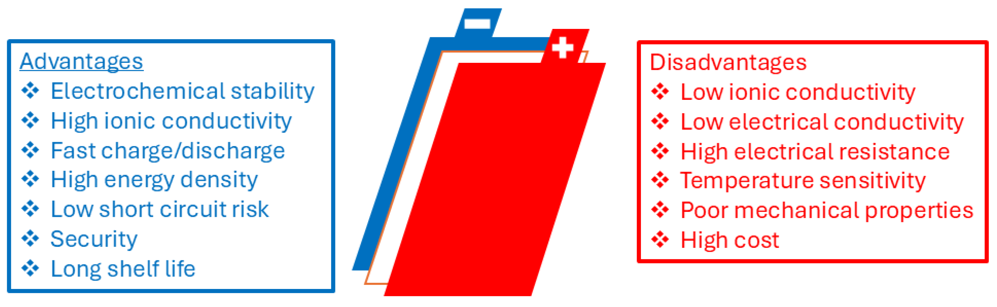
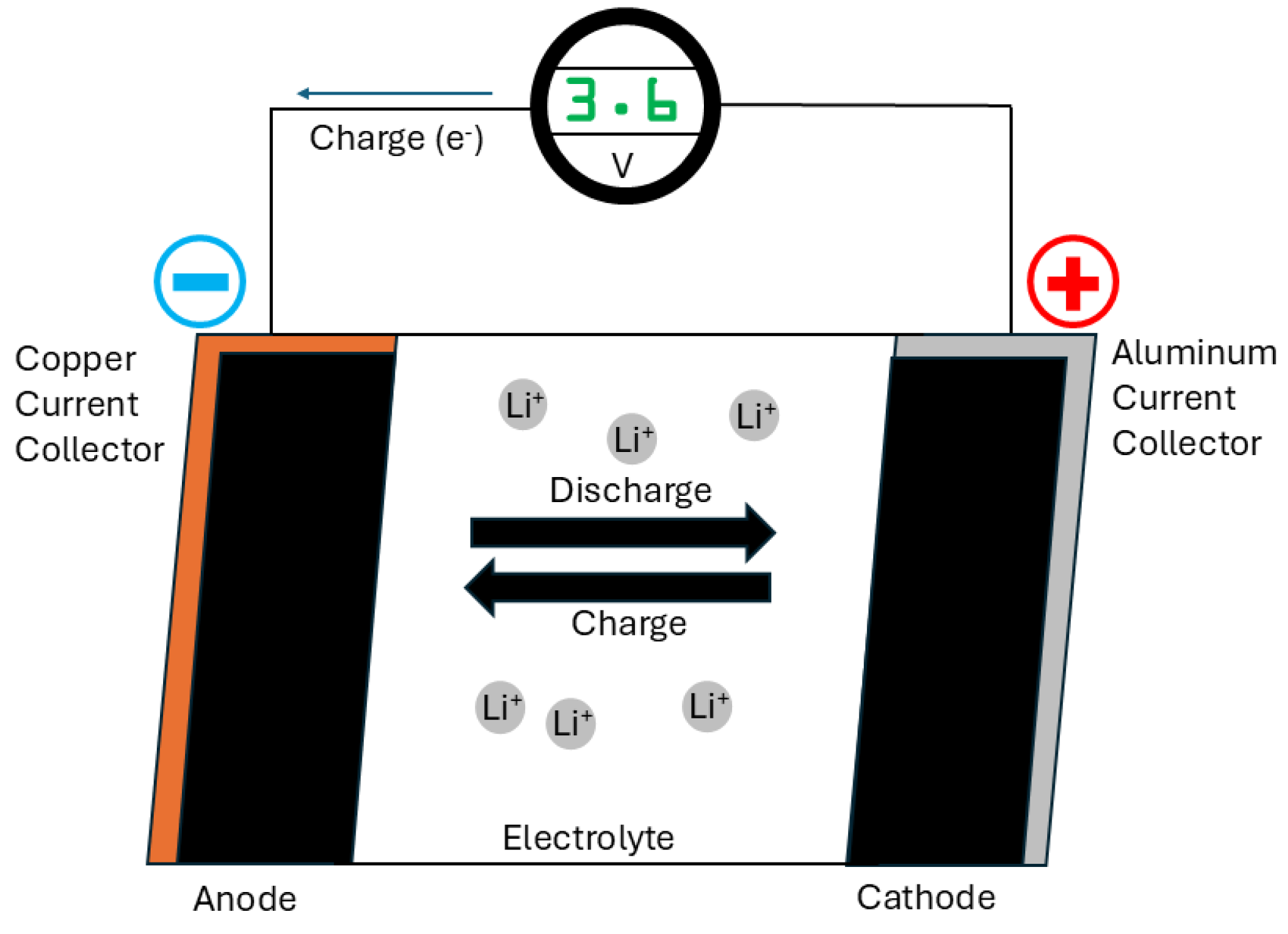
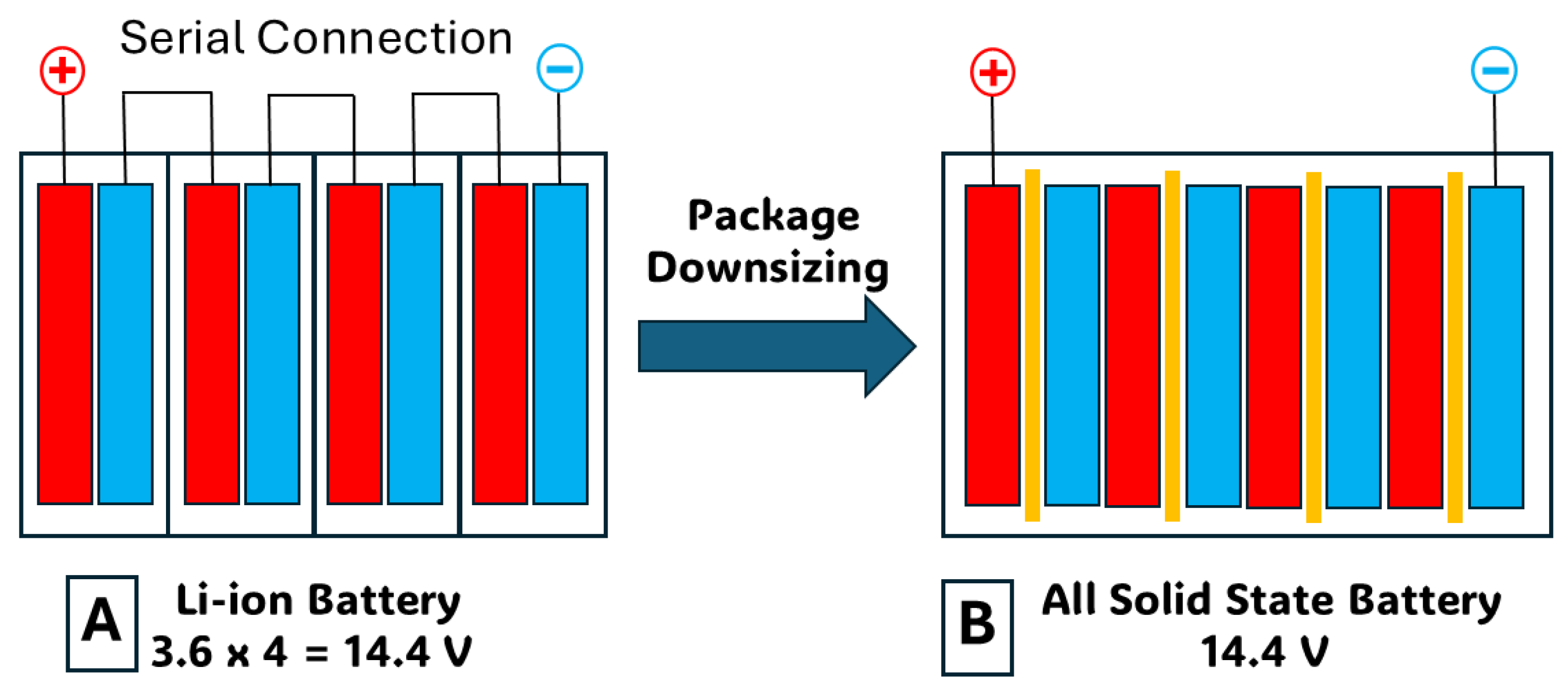
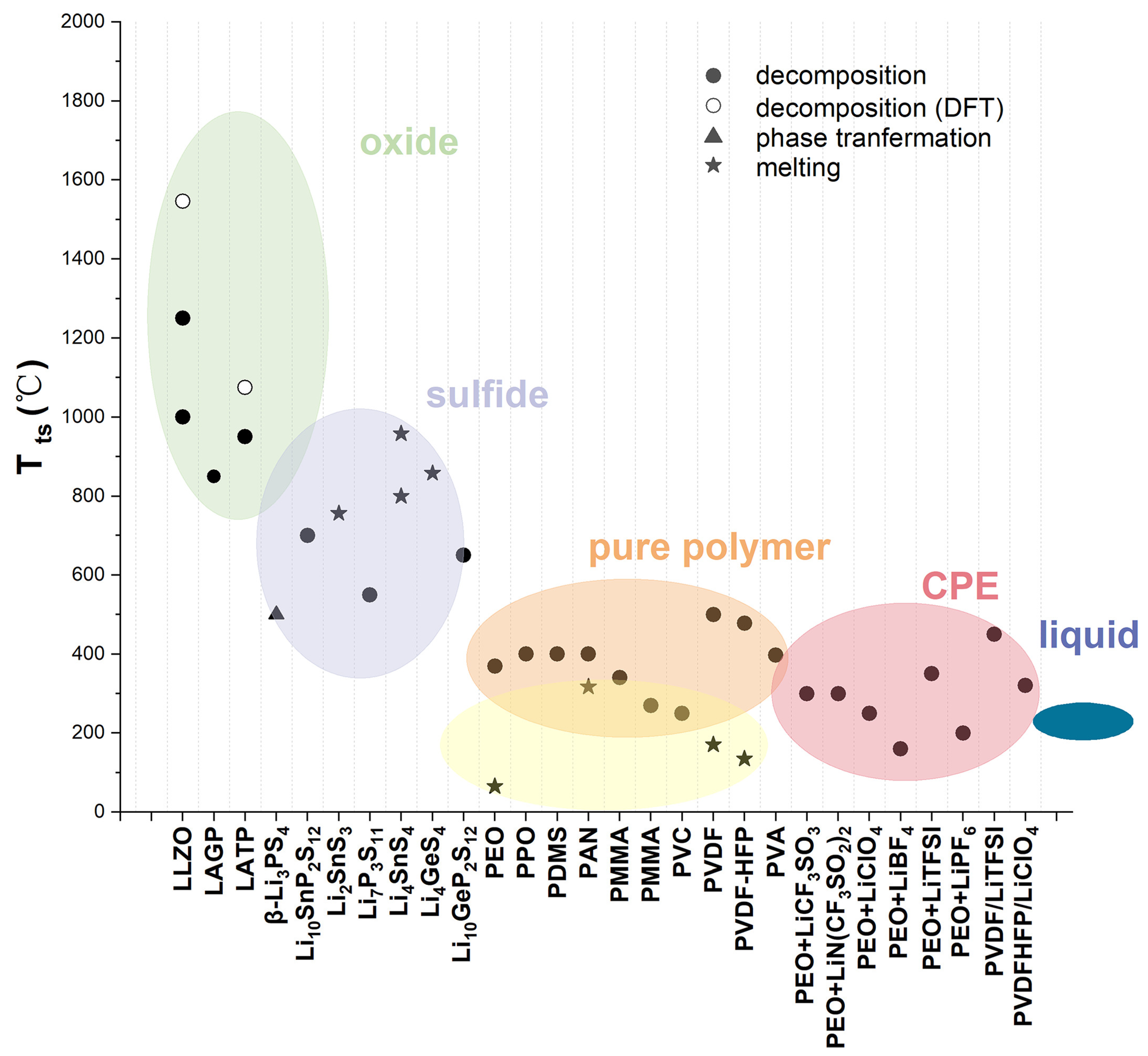
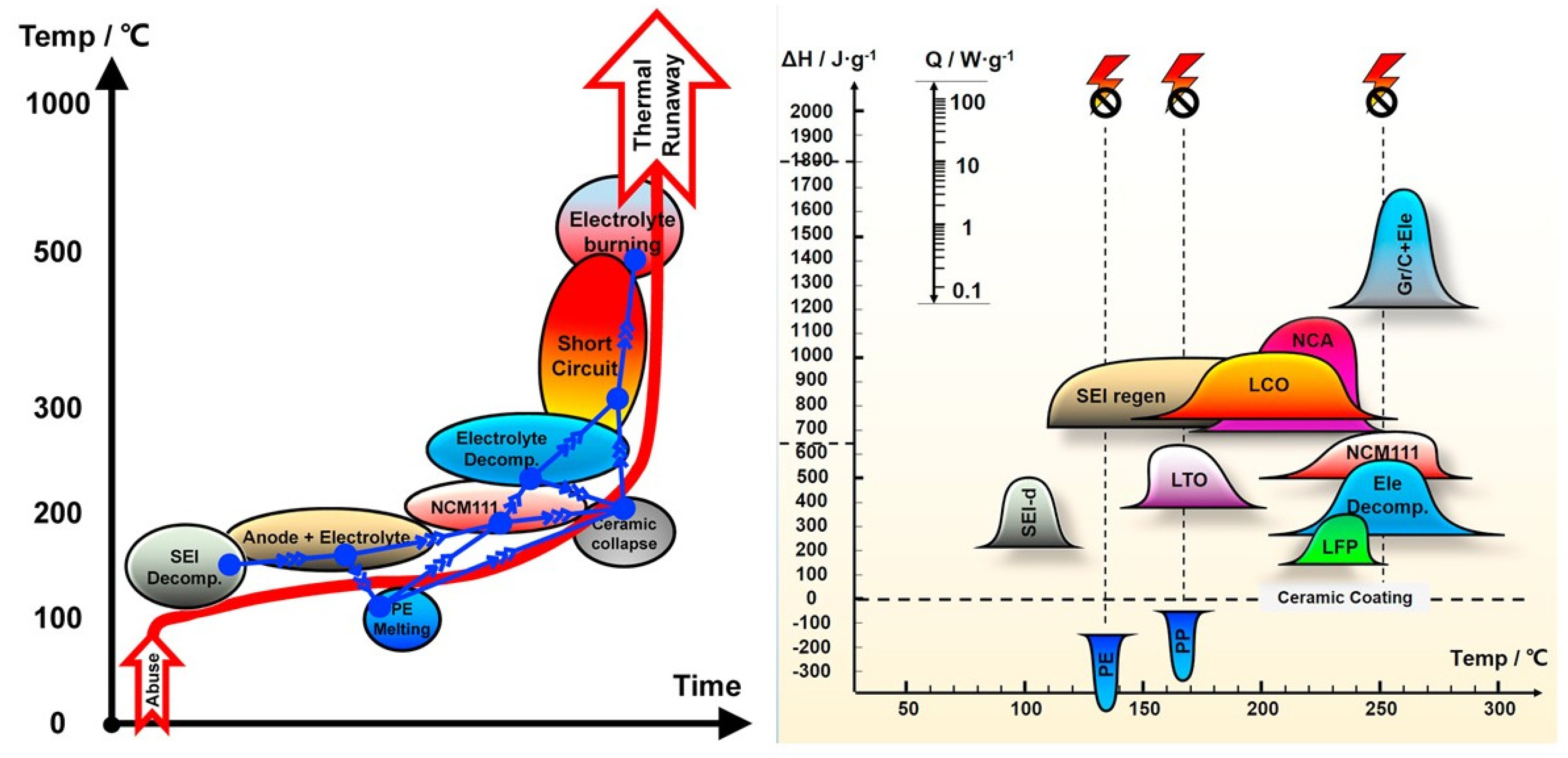
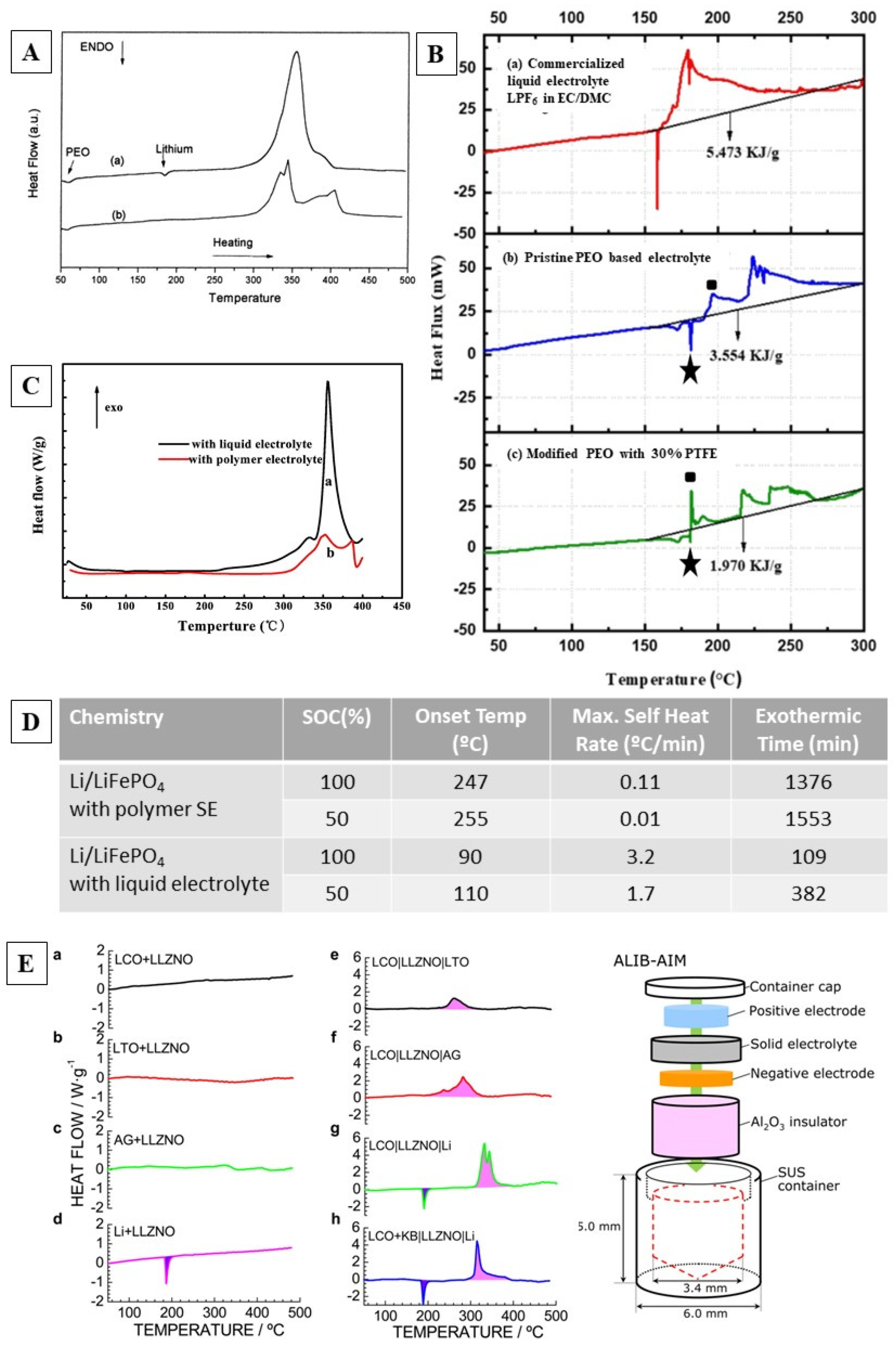

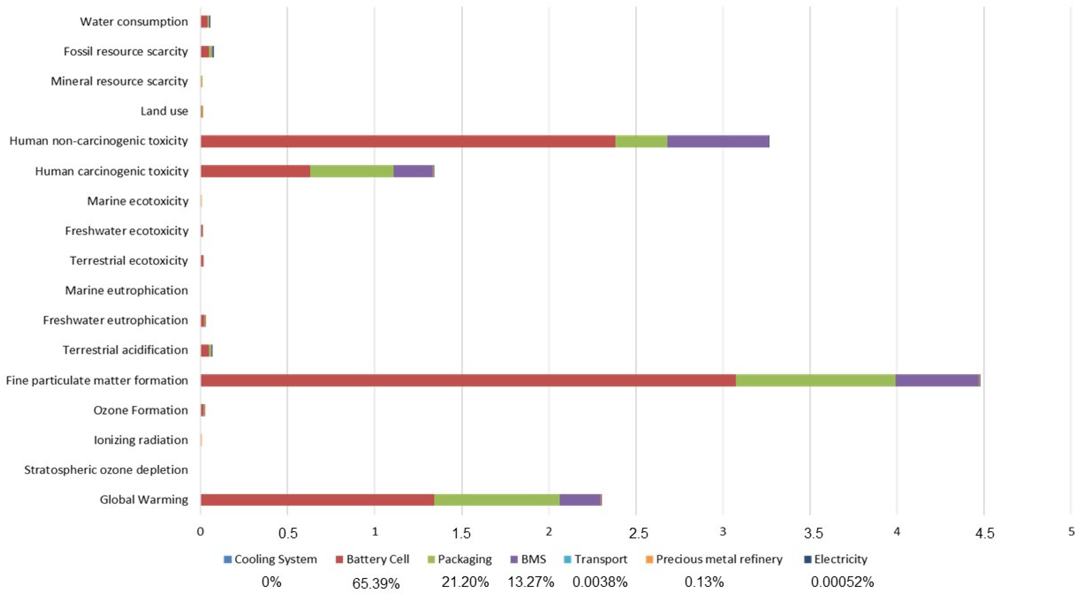
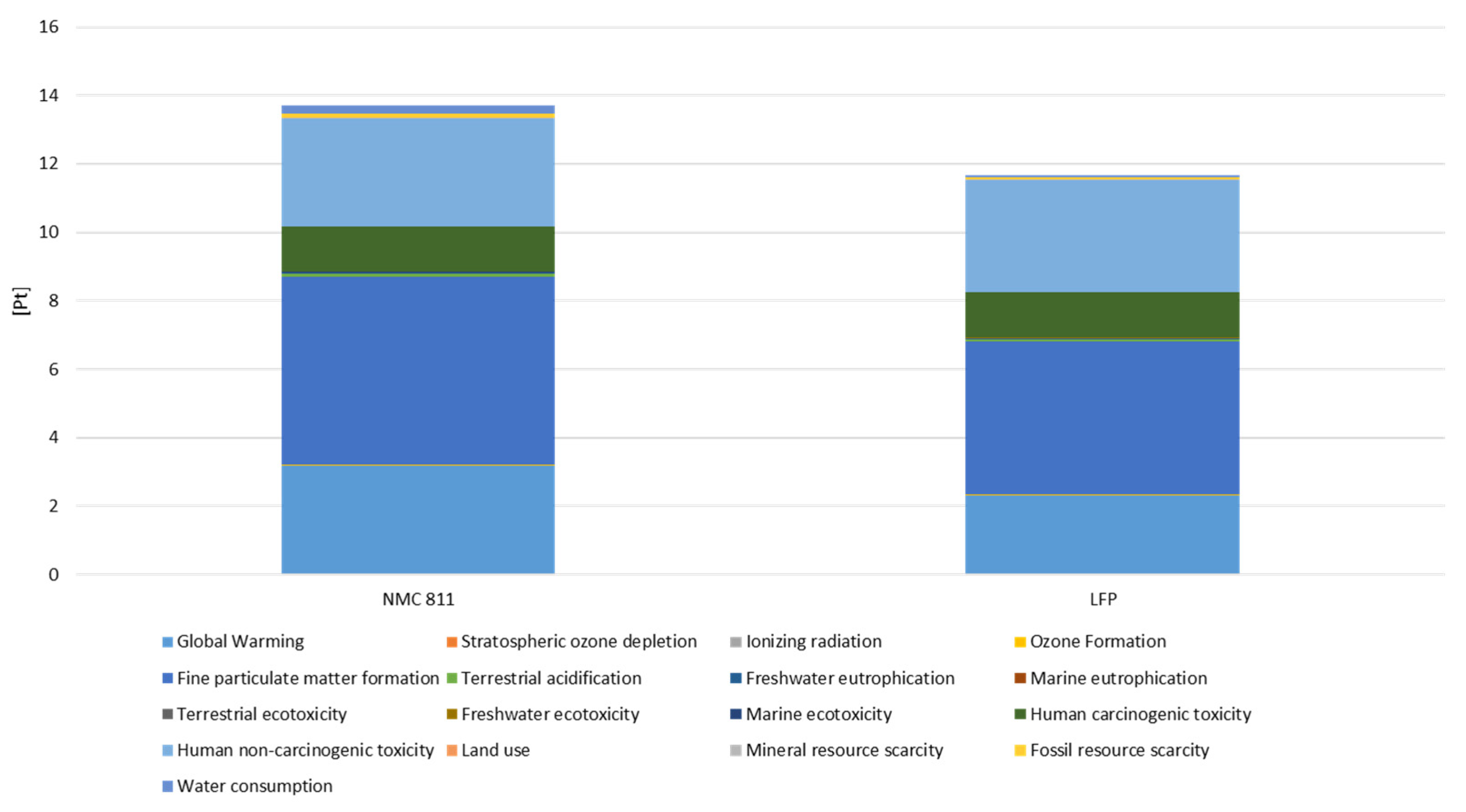
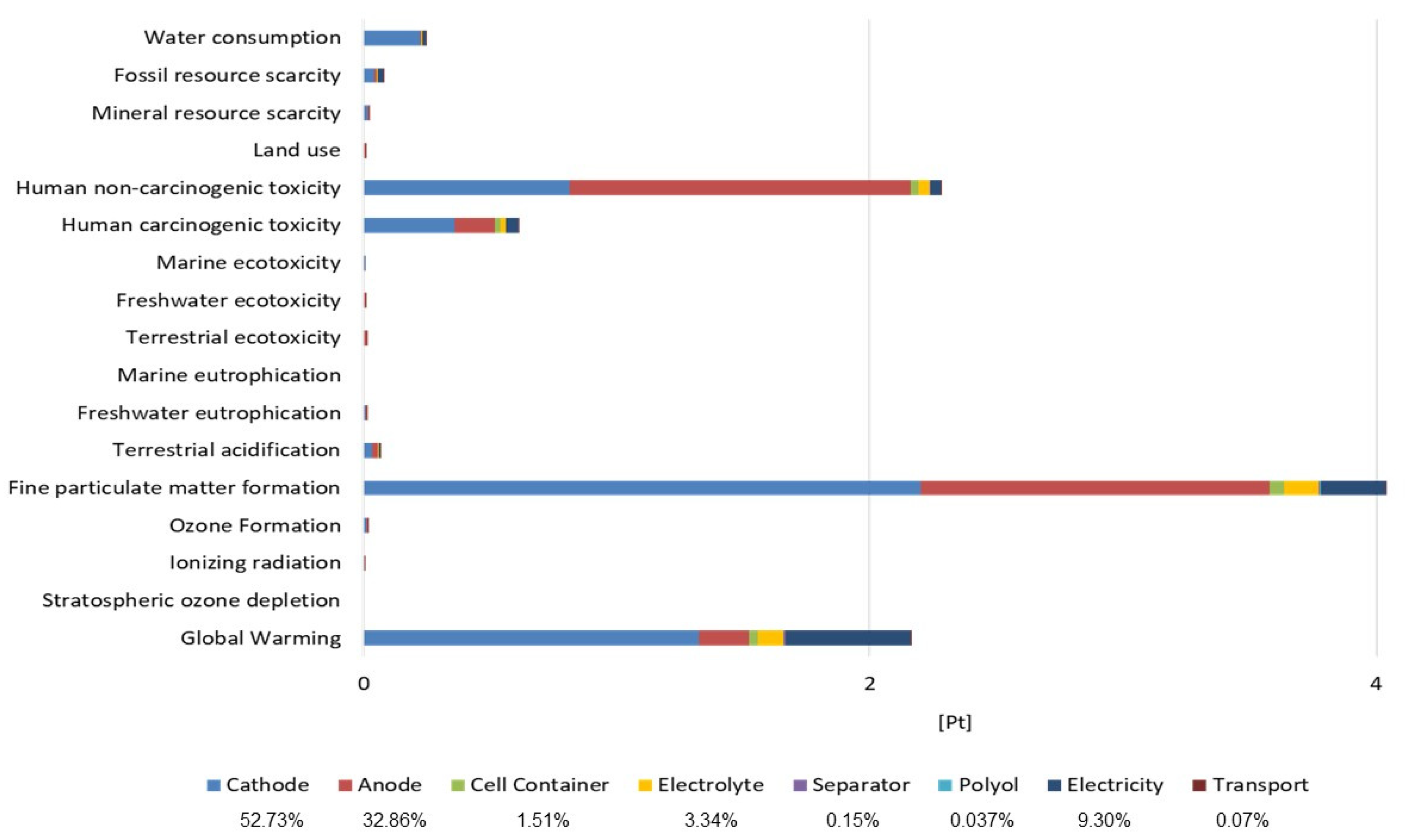
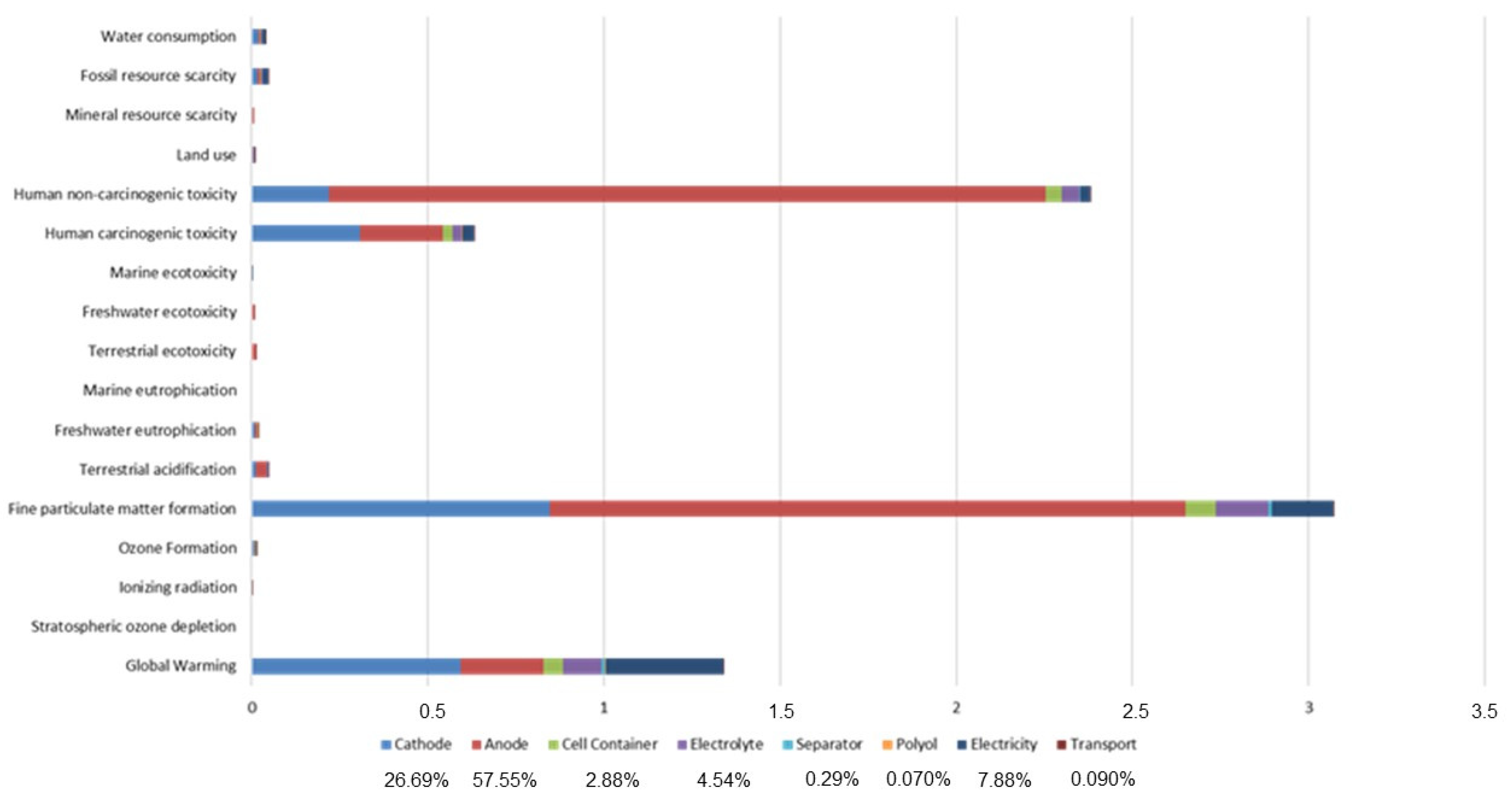


 Best indicator score of impact category.