Abstract
Developing photoelectrochemical systems that couple pollutant removal with resource recovery is of great significance for sustainable wastewater treatment. In this study, a dual-function photocatalytic fuel cell (PFC) was developed using a TiO2 nanotube photoanode modified with an amorphous CoOx cocatalyst, which markedly enhances charge separation and interfacial reaction kinetics. The optimized TiO2@CoOx electrode achieves a twofold enhancement in photocurrent compared to pristine TiO2. When applied to Cu2+-containing wastewater, the PFC achieved 91% Cu2+ removal under N2-purged conditions, with metallic Cu identified as the sole reduction product. Although dissolved oxygen reduced metal recovery efficiency through competitive electron consumption, it simultaneously increased power generation and improved anodic organic degradation. Overall, the results demonstrate that amorphous-CoOx-modified TiO2 photoanodes offer an effective platform for integrating sustainable energy production with wastewater remediation and valuable copper recovery.
1. Introduction
The discharge of wastewater containing both persistent organic pollutants and heavy metal ions presents an urgent environmental challenge, as these contaminants threaten aquatic ecosystems and human health [1,2,3]. Among these pollutants, copper is widely used in electroplating, mining, and electronic manufacturing, and its excessive discharge can lead to bioaccumulation and long-term environmental contamination [4,5]. Conventional treatment methods often suffer from high chemical consumption, secondary sludge generation, and poor recyclability of copper, limiting their sustainability [6,7,8,9]. Accordingly, technologies capable of simultaneously removing pollutants, recovering valuable metals, and reducing energy input are highly desirable.
Photocatalytic fuel cells (PFCs) represent an emerging class of self-driven systems that integrate photocatalysis with electrochemical energy conversion [10,11]. In a PFC, organic pollutants are oxidized at the photoanode, providing electrons that are consumed at the cathode for the reduction in electron acceptors (e.g., O2, Cr(VI), or heavy metal ions), thus enabling direct power generation. This multi-functional capability offers significant advantages over conventional photocatalysis or electrochemical treatment, including energy recovery, green operation, and the possibility of selective metal deposition [12,13,14,15,16].
TiO2-based photoanodes are widely employed in PFCs due to their excellent stability, low cost, and suitable band structure [12,17,18,19]. However, their practical efficiency is limited by rapid electron–hole recombination and sluggish interfacial kinetics. Amorphous transition-metal oxides have recently attracted increasing attention as effective cocatalysts because of their abundant active sites, flexible local coordination, and superior interfacial charge-transfer characteristics compared with their crystalline counterparts [20,21,22]. In particular, amorphous CoOx exhibits excellent hole-capture ability and promotes oxidation kinetics, making it a promising candidate for improving the performance of TiO2 photoanodes [23,24,25,26,27]. Despite these advantages, its application in photocatalytic fuel cells for simultaneous organic degradation, power generation, and copper recovery has not been extensively explored.
In this study, we design a TiO2@amorphous-CoOx nanotube photoanode and construct a dual-chamber photocatalytic fuel cell capable of simultaneously degrading organic pollutants, generating electrical power, and recovering Cu(II) as metallic copper. The schematic illustration of the self-driven PFC is shown in Scheme 1. The amorphous CoOx layer plays a critical role by accelerating charge separation, promoting hole utilization, and enhancing reaction kinetics, resulting in much higher photocurrent and power output compared with unmodified TiO2. Remarkably, the system achieves threefold enhancement in power density and 91% Cu2+ removal with metallic Cu as the exclusive reduction product. This work therefore provides a novel, resource-efficient, and energy-positive strategy for wastewater treatment and metal recovery, offering high potential for practical environmental applications.
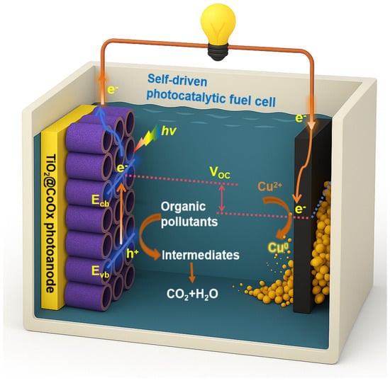
Scheme 1.
Schematic illustration of the self-driven photocatalytic fuel cell (PFC).
2. Results
2.1. Morphological and Photoelectrochemical Properties of TiO2 Nanotube Array Photoanodes
Vertically aligned TiO2 nanotube arrays (TNAs) were fabricated via anodic oxidation of titanium foil. During anodization, a compact TiO2 barrier layer initially forms on the Ti surface under the applied electric field [18]. Fluoride ions (F−) migrate toward the anode and chemically etch the oxide layer to produce soluble TiF62−, thereby generating pore nucleation sites. As shown in Figure 1a, after 10 min of oxidation, irregular pores with diameters up to ~60 nm appear on the surface [28]. With increasing oxidation time, pore density increases and the pore structure becomes more uniform. After 30 min (Figure 1b), continuous pore channels form, and small inter-pore voids emerge due to lateral etching [29].
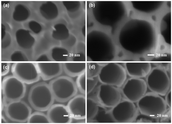
Figure 1.
Top-view SEM images of TiO2 nanotube arrays obtained after anodization for (a) 10 min, (b) 30 min, (c) 1 h, and (d) 2 h.
At 1 h (Figure 1c), highly ordered TiO2 nanotubes are fully developed, exhibiting an average inner diameter of ~90 nm and a tube-wall thickness of ~15 nm. When the anodization time is extended to 2 h (Figure 1d), the nanotubes become completely separated, with diameters expanding to ~100 nm. Some dissolution occurs at the tube openings due to prolonged etching. Meanwhile, as the tube length increases, the F− concentration at the tube bottom decreases, slowing the bottom-etching rate. Once the etching at the tube bottom equilibrates with dissolution at the opening, tube growth ceases. Cross-sectional SEM images (Figure 2) confirm that the tube length remains essentially unchanged, increasing only slightly from 5.1 μm (1 h) to 5.3 μm (2 h). The unique geometry of the TNA film enhances its light-harvesting ability by increasing optical reflection and refraction within the tubular channels while minimizing photon scattering losses in aqueous media [30,31]. Additionally, compared with nanorod or nanoparticle films, the nanotube architecture provides a substantially larger specific surface area with more exposed active sites, benefiting interfacial photoelectrochemical reactions [32,33].
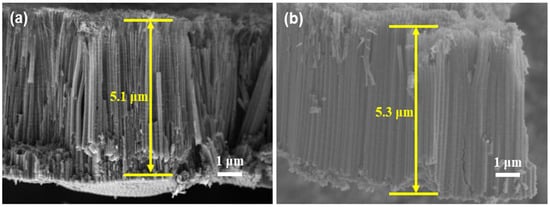
Figure 2.
Cross-sectional SEM images of TiO2 nanotube arrays formed after (a) 1 h and (b) 2 h of anodization.
The photoelectrochemical properties of the TNAs were further evaluated in a three-electrode configuration under AM 1.5G illumination (100 mW·cm−2). As shown in Figure 3a, the photocurrent density increases with oxidation time and reaches a maximum at 1 h (~0.16 mA·cm−2). Extending the anodization to 2 h results in decreased photocurrent, likely due to partial collapse or over-etching at the tube openings, which hinders charge transport. The crystalline structure of the optimized TNA was characterized by XRD (Figure 3b), where the diffraction peaks match the anatase TiO2 phase (JCPDS No. 21-1272), confirming successful formation of anatase nanotubes on the Ti substrate [18].
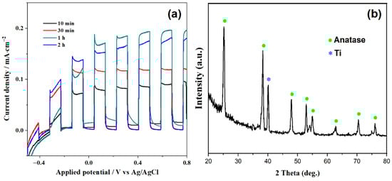
Figure 3.
(a) Photocurrent density of TiO2 nanotube arrays as a function of anodization time under AM 1.5G illumination (100 mW·cm−2). (b) XRD pattern of the optimized TiO2 nanotube photoanode.
2.2. Synthesis and Photoelectrochemical Characterization of TiO2@CoOx Photoanodes
The optimized TiO2 nanotube arrays (TNAs) anodized for 1 h were selected as the substrate for deposition of CoOx due to their superior photocurrent performance. The resulting TiO2@CoOx photoanodes exhibited significantly enhanced photoelectrochemical activity compared with pristine TiO2. Figure 4a shows the photocurrent response of TiO2@CoOx electrodes obtained with deposition durations of 0–240 s. The photocurrent density increases progressively with the loading of CoOx, reaching the highest value of 0.33 mA·cm−2 at a deposition time of 30 s. This improvement can be attributed to the cocatalytic function of CoOx, which promotes hole extraction and suppresses charge recombination at the semiconductor/electrolyte interface [34]. Excessive CoOx loading, however, would theoretically hinder light absorption and impede electron transport; therefore, the optimized loading amount is crucial for maximizing performance [35].
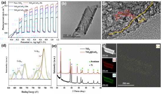
Figure 4.
(a) Photocurrent responses of TiO2@CoOx electrodes obtained with different CoOx deposition times. (b) TEM and (c) HRTEM images of TiO2@CoOx composite. (d) Co 2p XPS spectrum of TiO2@CoOx. (e) XRD patterns of TiO2 and TiO2@CoOx photoelectrodes. (f) EDS elemental mapping of Ti, O and Co distribution.
The morphology and microstructure of the TiO2@CoOx composite were further investigated by TEM. As presented in Figure 4b, the TiO2 nanotubes maintain their tubular morphology after CoOx deposition. High-resolution TEM analysis (Figure 4c) reveals that the outermost surface of the nanotube walls is uniformly coated with an amorphous CoOx layer, while the interior maintains the well-defined lattice fringes of anatase TiO2 (d = 0.35 nm for the (101) plane). This core–shell-like structure provides intimate contact between TiO2 and CoOx, facilitating efficient transfer of photogenerated holes to the CoOx catalytic sites [36]. To confirm elemental composition and distribution, energy-dispersive X-ray spectroscopy (EDS) mapping (Figure 4f) was performed. Ti and O signals originate from the TiO2 nanotube framework, whereas Co is uniformly dispersed along the tube exterior, indicating that the cobalt oxide formed a conformal coating over both the inner and outer walls of the nanotubes, further verifying the successful deposition of CoOx on the nanotube surface [37].
The chemical states of Co in the composite were examined using X-ray photoelectron spectroscopy (XPS). As shown in Figure 4d, the Co 2p spectrum exhibits peaks assignable to Co2+ and Co3+ species, indicating that the deposited layer is a mixed-valence CoOx phase. The presence of satellite peaks further supports this assignment. The crystalline phases were analyzed using X-ray diffraction (XRD), as shown in Figure 4e. The diffraction peaks of TiO2@CoOx remain dominated by anatase TiO2. No distinct peaks corresponding to crystalline cobalt oxides are observed, confirming that CoOx exists primarily in an amorphous state, which consistent with the HRTEM observations. Such amorphous catalytic layers typically provide abundant active sites and favorable charge-transfer properties, which explain the improved photocurrent performance of the TiO2@CoOx composite. The structural analyses demonstrate that depositing a thin amorphous CoOx layer onto TiO2 nanotubes effectively promotes interfacial charge separation and enhances photoelectrochemical activity, establishing TiO2@CoOx as a promising photoanode material for PFC applications [38,39].
2.3. Photocatalytic Fuel Cell Treatment of Cu(II)-Containing Wastewater and Recovery of Copper
To further evaluate the applicability of the optimized TiO2@CoOx photoanode in practical wastewater treatment, a dual-chamber photocatalytic fuel cell (PFC) was constructed. Glucose (0.05 M) was used as the anodic organic substrate, while the cathodic chamber contained simulated Cu(II)-containing wastewater (500 mg·L−1 Cu2+, pH 3.0). Graphite was used as the cathode for metal deposition. The system enables simultaneous oxidation of organic pollutants at the photoanode, reduction and recovery of Cu2+ at the cathode, and direct electricity generation. The polarization and power density curves of the system are shown in Figure 5a,b. As illustrated, introducing Cu2+ into the catholyte markedly enhances the power-generation performance of the PFC. The maximum power density increases to approximately 0.028 mW·cm−2, nearly three times higher than that of the blank Na2SO4 electrolyte, occurs at an operating voltage of 0.20 V and a current density of 0.14 mA cm−2.
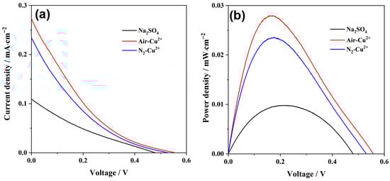
Figure 5.
(a) Polarization curves and (b) corresponding power-density curves of the PFC operated in different cathodic electrolyte.
However, when the catholyte is purged with N2, the overall cell output decreases. This behavior is opposite to that observed when Cr(VI) served as the electron acceptor [40], indicating that dissolved oxygen competes for electrons at the cathode and, in this system, actually promotes the electrical output. The possible cathodic reactions in the Cu(II) solution include:
where E0 is the standard redox potential.
Cu2+ + 2e− → Cu, E0 = 0.34 V
2Cu2+ + H2O + 2e− → Cu2O + 2H+, E0 = 0.21 V
Cu2O + 2H+ + 2e− → 2Cu + H2O, E0 = 0.06 V
2H+ + 1/2O2 + 2e− → H2O, E0 = 1.23 V
The theoretical open-circuit potentials of these redox couples can be estimated using the Nernst equation:
where R is the gas constant, 8.314 J·mol−1·K−1; n is the number of transferred electrons; F is the Faraday constant, 96,485.3 C·mol−1.
When the catholyte containing 500 mg·L−1 Cu2+ at pH 3.0, Equations (5) and (6) yield equilibrium potentials of 0.276 V and 0.256 V vs. SHE, corresponding to 0.45 V and 0.43 V vs. RHE for Cu2+/Cu and Cu2+/Cu2O, respectively. Experimentally, after N2 purging, the measured open-circuit potential (OCP) of the cathode reaches 0.14 V vs. Ag/AgCl, corresponding to 0.52 V vs. RHE, which is far higher than the theoretical Cu deposition potentials. This indicates that even under continuous N2 purging, trace dissolved oxygen remains, contributing to a mixed potential at the cathode. When the catholyte is not purged with N2, the OCP further increases to 0.18 V vs. Ag/AgCl (≈0.56 V vs. RHE). According to Equation (8), the O2/H2O couple exhibits a potential of 1.04 V vs. RHE at pH 3.0, making oxygen thermodynamically more favorable for electron reduction. Thus, the cathode potential represents a mixed potential arising from both Cu2+ reduction and oxygen reduction, and this mixed reaction pathway collectively enhances the overall electrical output of the PFC [41].
The Cu2+ removal performance of the PFC system is presented in Figure 6a. Under the N2-purged condition, Cu2+ is rapidly reduced and deposited onto the graphite cathode, achieving a high removal efficiency of 91% within 12 h. In comparison, when the catholyte is not purged with N2, the removal efficiency decreases to 65%. Moreover, in the air-saturated condition, the decline in Cu2+ concentration progressively slows over time, indicating that as the Cu2+ concentration decreases, a greater fraction of photogenerated electrons is consumed by the competing oxygen reduction reaction (ORR) rather than by Cu2+ reduction.
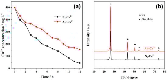
Figure 6.
(a) Temporal change in Cu2+ concentration during PFC operation under air-saturated and N2-purged conditions. (b) XRD patterns of deposited cathode products.
This competitive electron consumption is further reflected in the calculated cathodic efficiencies: approximately 80% under N2 purging, but only 45% without purging. These results demonstrate that dissolved oxygen participates in the cathodic reduction reaction under both conditions; however, in the absence of N2 purging, the higher level of dissolved oxygen captures more electrons, thereby suppressing Cu2+ reduction efficiency. Despite lowering Cu2+ removal, the involvement of oxygen enhances the overall electrical output of the PFC and promotes anodic oxidation of organics. Accordingly, the chemical oxygen demand (COD) removal in the anodic chamber increases from 287 mg·L−1 (N2-purged) to 336 mg·L−1 (without purging). Therefore, N2 purging improves Cu2+ removal efficiency by suppressing electron competition from O2, but the absence of ORR lowers the cathode potential, thereby reducing the PFC voltage output and anodic oxidation. This dual effect highlights that a balance between metal recovery and power generation must indeed be optimized depending on the desired application [42].
The XRD patterns of the cathodic deposits obtained under both N2-purged and air-saturated conditions are shown in Figure 6b. In both cases, all diffraction peaks match well with the standard cubic phase of metallic copper (JCPDS No. 04-0836), indicating that the recovered product consists exclusively of Cu0, with no detectable Cu2O. Although the thermodynamic redox potentials of the Cu2+/Cu and Cu2+/Cu2O couples differ by only 0.02 V under the initial experimental conditions, no Cu2O is observed. This can be attributed to the acidic environment (pH 3.0), where the high concentration of H+ and abundant electron supply from the external circuit thermodynamically and kinetically favor the complete reduction of any intermediate Cu(I) species [43]. As described by Equation (6), any Cu2O formed during the process would undergo further reduction to Cu0 in the presence of excess H+ and electrons, ultimately yielding exclusively metallic copper on the cathode surface.
The morphology of the deposited copper was further characterized by SEM (Figure 7a–d). Under N2-purged conditions, the cathode surface is densely covered with well-defined polyhedral metallic copper crystals of uniform size (Figure 7a,b). These compact deposits indicate rapid and efficient Cu2+ reduction in the absence of oxygen competition [44]. In contrast, the air-saturated system yields fewer and more dispersed Cu particles (Figure 7c,d), consistent with the presence of O2 competing with Cu2+ for electrons during the reduction process. The reduced deposition density correlates well with the lower Cu2+ removal efficiency observed in Figure 6a.
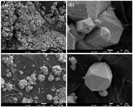
Figure 7.
SEM images of copper deposits on the graphite cathode under (a,b) N2-purged Cu2+ solution and (c,d) air-saturated Cu2+ solution.
Overall, these results demonstrate that the TiO2@CoOx-based PFC system effectively couples anodic degradation of organic pollutants with cathodic copper recovery while generating electrical power. The presence of dissolved oxygen enhances power output but competes with Cu2+ reduction, influencing metal recovery efficiency [45]. Balancing these factors allows the PFC system to be tailored for practical applications in resource recovery from industrial wastewater.
3. Discussion
This study demonstrates that the TiO2@CoOx photoanode enables synergistic organic oxidation, copper recovery, and power generation in a PFC system, driven by efficient charge separation via the amorphous CoOx cocatalyst. The trade-off between high Cu recovery (91%) under N2 and enhanced power output with O2 confirms our hypothesis that electron transfer pathways can be modulated by operational conditions. These findings advance PFCs beyond wastewater treatment toward integrated resource recovery and energy generation. Future work should focus on developing oxygen-tolerant catalytic interfaces and validating the system with real wastewater streams for multicomponent metal recovery.
4. Materials and Methods
4.1. Preparation of TiO2 Nanotube Array Photoanodes
TiO2 nanotube array (TNA) photoanodes were fabricated via anodic oxidation. Titanium foil (99.6% purity, 0.5 mm thickness) was cut into pieces of 2 × 4 cm2, mechanically flattened, washed, and dried. The Ti sheets were then immersed in freshly prepared aqua regia and stored in a sealed acid-resistant chamber for 48 h. After pretreatment, the Ti sheets were ultrasonically cleaned with deionized water and ethanol, dried with N2, and stored in ethanol prior to use.
The anodization electrolyte consisted of ethylene glycol, NH4F, and water, with a volumetric ratio of ethylene glycol/water = 93:7 and an NH4F mass fraction of 0.3%. During anodization, the Ti sheet served as the anode and a copper plate as the cathode, with an inter-electrode distance of 2 cm. A constant bias of 50 V was applied. After anodization, the TNA electrodes were rinsed with ethanol and deionized water, blown dry with nitrogen, and then annealed in a muffle furnace at 500 °C for 2 h. The furnace was allowed to cool naturally to obtain crystalline TiO2 nanotube array electrodes.
4.2. Preparation of TiO2@CoOx Photoanodes
CoOx was deposited onto the TiO2 nanotubes by cathodic electrodeposition. The as-prepared TiO2 nanotube electrodes were immersed for 10 min in an aqueous solution containing 0.5 mM H3BO3, 0.5 mM L-histidine, and 10 mM CoSO4. Subsequently, CoOx was electrodeposited under a constant cathodic current density of 1 mA·cm−2 for 30 s, resulting in TiO2@CoOx composite photoanodes.
4.3. Assembly of Photocatalytic Fuel Cells (PFCs)
The synthesized TiO2 nanotube array (or TiO2@CoOx) electrode was used as the photoanode, and a graphite plate of the same size served as the cathode. The cell consisted of two separate chambers divided by a bipolar membrane. The anodic chamber was filled with electrolyte containing the model organic pollutant glucose, while the cathodic chamber contained the target heavy-metal solution. The working volumes of the anolyte and catholyte were 33 mL and 20 mL, respectively. In both chambers, 0.5 M Na2SO4 was used as the supporting electrolyte, and the pH was adjusted using dilute H2SO4 or NaOH. A Ag/AgCl electrode with saturated KCl was used as the reference. The conversion from Ag/AgCl to RHE has been corrected in the text according to:
Before illumination, the assembled PFC was allowed to equilibrate in the dark under open-circuit conditions for 40 min to achieve adsorption–desorption balance. A 300 W Xe lamp equipped with an AM 1.5G filter (100 mW·cm−2) served as the light source.
4.4. Analytical Methods
Photoelectrochemical measurements were performed using a CHI 660E electrochemical workstation (Chen Hua Instruments, Shanghai, China). A Xe lamp (CHF-XM500, Beijing Perfectlight Co., Ltd., Beijing, China) with an AM 1.5G filter was used to provide simulated sunlight at 100 mW·cm−2. In the three-electrode configuration, the photoanode served as the working electrode, Pt foil as the counter electrode, and a saturated Ag/AgCl electrode as the reference. Unless stated otherwise, all electrochemical characterizations were conducted in 0.5 M Na2SO4. The polarization curves were recorded in a two electrode configuration, using the photoanode and a graphite cathode under 100 mW·cm−2 simulated AM 1.5G illumination. The external resistance was varied using the CHI electrochemical workstation, and the cell voltage and current were measured after stabilization at each load. The current density was normalized to the illuminated area of the photoanode. The output power density was calculated based on the polarization curves according to:
where P is power density, U is cell voltage, I is operating current, S is illuminated area of the photoanode.
The concentration of Cu2+ was determined using ICP-MS (NexION 350, PerkinElmer, Waltham, MA, USA). The removal efficiency of pollutants was calculated as:
where
is the initial concentration,
is the concentration at time t.
The cathodic efficiency of metal-ion removal was calculated using:
where V is the volume of the catholyte, b is the number of transferred electrons, here b = 2, based on the target reduction reaction of Cu2+ to metallic Cu0 (Cu2+ + 2e− → Cu), F is the Faraday constant, I is the external current.
5. Conclusions
In this work, a TiO2@CoOx-based photocatalytic fuel cell (PFC) was constructed for simultaneous organic pollutant oxidation, Cu(II) recovery, and electricity generation. The TiO2 nanotube arrays provided a highly ordered structure for efficient light harvesting, while the amorphous CoOx cocatalyst significantly enhanced charge separation and photoelectrochemical activity. When applied in the PFC system, the optimized photoanode achieved a maximum power density of 0.028 mW·cm−2 and enabled effective copper recovery, reaching 91% removal under N2-purged conditions. Although dissolved oxygen reduced metal recovery efficiency due to competitive electron consumption, it simultaneously improved power output and anodic organic degradation. XRD and SEM analyses confirmed that metallic Cu was the sole reduction product under all conditions. Overall, this study demonstrates the potential of TiO2@CoOx photoanodes for integrating wastewater treatment with resource recovery and sustainable energy production.
Author Contributions
Conceptualization, X.-H.L. and R.Y.; methodology, X.-H.L. and C.F.; software, R.Y.; validation, X.-H.L., R.Y. and N.L.; formal analysis, X.-H.L.; investigation, X.-H.L.; resources, S.W. and X.Z.; data curation, S.W. and Y.M.; writing—original draft, X.-H.L.; writing—review and editing, X.-H.L., X.Z. and P.D.; visualization, X.-H.L.; supervision, X.-H.L., S.W. and C.F.; project administration, X.-H.L. and N.L.; funding acquisition, C.F. All authors have read and agreed to the published version of the manuscript.
Funding
The National Natural Science Foundation of China (52206277), the China Postdoctoral Science Foundation (2022MD723821).
Institutional Review Board Statement
Not applicable.
Informed Consent Statement
Not applicable.
Data Availability Statement
The original contributions presented in this study are included in the article. Further inquiries can be directed to the corresponding author.
Conflicts of Interest
Authors Nan Li and Shaohui Wang were employed by the company Xi’an Thermal Power Research Institute Co., Ltd. Author Xiaoyuan Zhang was employed by the company CHN ENERGY Feixian Power Generation Co., Ltd. Authors Yunteng Ma, Chaoqun Fan and Peipei Du were employed by the company CHN ENERGY GD POWER Langfang Thermal Power Plant. The remaining authors declare that the research was conducted in the absence of any commercial or financial relationships that could be construed as a potential conflict of interest.
Abbreviations
The following abbreviations are used in this manuscript:
| TNA | TiO2 nanotube array |
| PFCs | Photocatalytic Fuel Cells |
| OCP | open-circuit potential |
| COD | Chemical Oxygen Demand |
References
- Deng, S.; Zhang, X.; Zhu, Y.; Zhuo, R. Recent Advances in Phyto-Combined Remediation of Heavy Metal Pollution in Soil. Biotechnol. Adv. 2024, 72, 108337. [Google Scholar] [CrossRef]
- Guan, X.; Ru, X.; Qiu, G.; Li, Z.; Cheng, X.; Ke, X.; Chen, A.; Wei, C. Probing the National Development from Heavy Metals Contamination in River Sediments. J. Clean. Prod. 2023, 419, 138164. [Google Scholar] [CrossRef]
- Jia, J.; Gao, X.; Wu, Z.; Lei, L. 4D Freeze-Driven Purification of Heavy-Metal Contaminated Sandy Soil. J. Clean. Prod. 2025, 489, 144676. [Google Scholar] [CrossRef]
- Izydorczyk, G.; Mikula, K.; Skrzypczak, D.; Moustakas, K.; Witek-Krowiak, A.; Chojnacka, K. Potential Environmental Pollution from Copper Metallurgy and Methods of Management. Environ. Res. 2021, 197, 111050. [Google Scholar] [CrossRef]
- Wang, Y.; Yan, Q.; Shi, Y.; Long, M. Copper Toxicity in Animals: A Review. Biol. Trace Elem. Res. 2024, 203, 2675–2686. [Google Scholar] [CrossRef]
- Ma, S.; Xing, P.; Li, H.; Wang, C.; Hou, X.; Cun, Z.; Liu, M.; Yan, R. Recovery of High-Grade Copper from Waste Polyester Imide Enameled Wires by Pyrolysis and Ultrasonic Treatment. Resour. Conserv. Recycl. 2023, 196, 107034. [Google Scholar] [CrossRef]
- Sun, J.; Xie, Z.; Jiang, T.; Shen, P.; Liu, D. Experimental and Mechanistic Study on the Recovery of Copper, Iron, Zinc and Cobalt from Copper Slag by Low-Temperature Roasting with Sulfuric Acid-Ammonium Persulfate Combined with Water-Leaching. Chem. Eng. J. 2025, 521, 166710. [Google Scholar] [CrossRef]
- Nag, A.; Singh, M.K.; Morrison, C.A.; Love, J.B. Efficient Recycling of Gold and Copper from Electronic Waste by Selective Precipitation. Angew. Chem. Int. Ed. 2023, 62, e202308356. [Google Scholar] [CrossRef]
- Yousefzadeh, S.; Yaghmaeian, K.; Mahvi, A.H.; Nasseri, S.; Alavi, N.; Nabizadeh, R. Comparative Analysis of Hydrometallurgical Methods for the Recovery of Cu from Circuit Boards: Optimization Using Response Surface and Selection of the Best Technique by Two-Step Fuzzy AHP-TOPSIS Method. J. Clean. Prod. 2020, 249, 119401. [Google Scholar] [CrossRef]
- He, Y.; Chen, K.; Leung, M.K.H.; Zhang, Y.; Li, L.; Li, G.; Xuan, J.; Li, J. Photocatalytic Fuel Cell—A Review. Chem. Eng. J. 2022, 428, 131074. [Google Scholar] [CrossRef]
- Zhang, J.; Zheng, J.; Yang, W. Green Supercapacitor Assisted Photocatalytic Fuel Cell System for Sustainable Hydrogen Production. Chem. Eng. J. 2021, 403, 126368. [Google Scholar] [CrossRef]
- Liu, X.-H.; He, Y.; Li, Z.; Cheng, A.-H.; Song, Z.; Yu, Z.-X.; Chai, S.; Cheng, C.; He, C. Size Transformation of Au Nanoclusters for Enhanced Photocatalytic Hydrogen Generation: Interaction Behavior at Nanocluster/Semiconductor Interface. J. Colloid Interface Sci. 2023, 651, 368–375. [Google Scholar] [CrossRef]
- Hu, Q.; Chen, S.; Wågberg, T.; Zhou, H.; Li, S.; Li, Y.; Tan, Y.; Hu, W.; Ding, Y.; Han, X. Developing Insoluble Polyoxometalate Clusters to Bridge Homogeneous and Heterogeneous Water Oxidation Photocatalysis. Angew. Chem. Int. Ed. 2023, 62, e202303290. [Google Scholar] [CrossRef]
- Yan, X.; Fu, X.; Xiao, F. Filling the Gap: Atomically Precise Metal Nanoclusters-induced Z-scheme Photosystem toward Robust and Stable Solar Hydrogen Generation. Adv. Funct. Mater. 2023, 33, 2303737. [Google Scholar] [CrossRef]
- Kamat, P.V.; Sivula, K. Celebrating 50 Years of Photocatalytic Hydrogen Generation. ACS Energy Lett. 2022, 7, 3149–3150. [Google Scholar] [CrossRef]
- Li, R.; Luan, J.; Zhang, Y.; Jiang, L.; Yan, H.; Chi, Q.; Yan, Z. A Review of Efficient Photocatalytic Water Splitting for Hydrogen Production. Renew. Sustain. Energy Rev. 2024, 206, 114863. [Google Scholar] [CrossRef]
- Wang, Y.; Liu, X.-H.; Wang, Q.; Quick, M.; Kovalenko, S.A.; Chen, Q.-Y.; Koch, N.; Pinna, N. Insights into Charge Transfer at an Atomically Precise Nanocluster/Semiconductor Interface. Angew. Chem. Int. Ed. 2020, 59, 7748–7754. [Google Scholar] [CrossRef]
- Wang, Y.; Liu, X.-H.; Kovalenko, S.A.; Chen, Q.-Y.; Pinna, N. Atomically Precise Bimetallic Nanoclusters as Photosensitizers in Photoelectrochemical Cells. Chem. Eur. J. 2019, 25, 4814–4820. [Google Scholar] [CrossRef]
- Li, B.; Zheng, H.; Zhou, T.; Lu, Q.; Chen, M.; Sun, H.; Zhang, Y.; Zhang, Y.; Li, D.; Zi, B.; et al. Asymmetric Coordination Enhances the Synergy of Pt Species Dual Active Sites for Efficient Photocatalytic H2 Evolution. Nat. Commun. 2025, 16, 8276. [Google Scholar] [CrossRef]
- Singh, S.; Parveen, S.; Clarizia, L.; Kumar, P. An Insight into Photo-Catalytic Degradation Mechanism of Persistent Pollutants with Transition Metal Oxides and Their Composites: Photocatalysis Mechanism, Rate Affecting Parameters, and Removal Pathways. Catal. Rev. Sci. Eng. 2025, 1–49. [Google Scholar] [CrossRef]
- Rahman, M.Z.; Raziq, F.; Zhang, H.; Gascon, J. Key Strategies for Enhancing H2 Production in Transition Metal Oxide Based Photocatalysts. Angew. Chem. Int. Ed. 2023, 62, e202305385. [Google Scholar] [CrossRef]
- Sachs, M.; Harnett-Caulfield, L.; Pastor, E.; Davies, B.; Sowood, D.J.C.; Moss, B.; Kafizas, A.; Nelson, J.; Walsh, A.; Durrant, J.R. Metal-Centred States Control Carrier Lifetimes in Transition Metal Oxide Photocatalysts. Nat. Chem. 2025, 17, 1348–1355. [Google Scholar] [CrossRef]
- Simanaitienė, A.; Barauskienė, I.; Varnagiris, Š.; Urbonavičius, M.; Šulčiūtė, A. Mixed Zinc–Cobalt Oxide Coatings for Photocatalytic Applications. Appl. Phys. A 2020, 126, 695. [Google Scholar] [CrossRef]
- Li, H.; Xia, M.; Chong, B.; Xiao, H.; Zhang, B.; Lin, B.; Yang, B.; Yang, G. Boosting Photocatalytic Nitrogen Fixation via Constructing Low-Oxidation-State Active Sites in the Nanoconfined Spinel Iron Cobalt Oxide. ACS Catal. 2022, 12, 10361–10372. [Google Scholar] [CrossRef]
- Hou, J.; Wang, K.; Zhang, X.; Wang, Y.; Su, H.; Yang, C.; Zhou, X.; Liu, W.; Hu, H.; Wang, J.; et al. Synergistic Defect Sites and CoOx Nanoclusters in Polymeric Carbon Nitride for Enhanced Photocatalytic H2O2 Production. ACS Catal. 2024, 14, 10893–10903. [Google Scholar] [CrossRef]
- Raja, A.; Kang, M.; Im, Y.; Bahajjaj, A.A.A. Effective Photocatalytic Hydrogen Generation and Degradation for Single Cobalt and Tungsten Metal Atom Oxide Anchored on Titanium Dioxide-Bismuth Molybdate-Reduced Graphene Oxide. J. Clean. Prod. 2024, 480, 144114. [Google Scholar] [CrossRef]
- Wang, M.; Wang, J.-Q.; Xi, C.; Cheng, C.-Q.; Zou, C.-Q.; Zhang, R.; Xie, Y.-M.; Guo, Z.-L.; Tang, C.-C.; Dong, C.-K.; et al. A Hydrogen-Deficient Nickel-Cobalt Double Hydroxide for Photocatalytic Overall Water Splitting. Angew. Chem. Int. Ed. 2020, 59, 11510–11515. [Google Scholar] [CrossRef]
- Santos, J.S.; Sikora, M.S.; Trivinho-Strixino, F.; Praserthdam, S.; Praserthdam, P. A Comprehensive Review of Anodic TiO2 Films as Heterogeneous Catalysts for Photocatalytic and Photoelectrocatalytic Water Disinfection. J. Water Process Eng. 2025, 69, 106589. [Google Scholar] [CrossRef]
- Santos, J.S.; Fereidooni, M.; Márquez, V.; Paz-López, C.V.; Villanueva, M.S.; Buijnsters, J.G.; Praserthdam, S.; Praserthdam, P. Photoactivity of Amorphous and Crystalline TiO2 Nanotube Arrays (TNA) Films in Gas Phase CO2 Reduction to Methane with Simultaneous H2 Production. Environ. Res. 2024, 244, 117919. [Google Scholar] [CrossRef]
- Hsu, M.-Y.; Hsu, H.-L.; Leu, J. TiO2 Nanowires on Anodic TiO2 Nanotube Arrays (TNWs/TNAs): Formation Mechanism and Photocatalytic Performance. J. Electrochem. Soc. 2012, 159, H722–H727. [Google Scholar] [CrossRef]
- Lu, D.; Zhang, M.; Zhang, Z.; Li, Q.; Wang, X.; Yang, J. Self-Organized Vanadium and Nitrogen Co-Doped Titania Nanotube Arrays with Enhanced Photocatalytic Reduction of CO2 into CH4. Nanoscale Res. Lett. 2014, 9, 272. [Google Scholar] [CrossRef]
- Wang, S.; Zhang, Z.; Huo, W.; Zhu, K.; Zhang, X.; Zhou, X.; Fang, F.; Xie, Z.; Jiang, J. Preferentially Oriented Ag-TiO2 Nanotube Array Film: An Efficient Visible-Light-Driven Photocatalyst. J. Hazard. Mater. 2020, 399, 123016. [Google Scholar] [CrossRef]
- Santos, J.S.; Tarek, M.; Sikora, M.S.; Praserthdam, S.; Praserthdam, P. Anodized TiO2 Nanotubes Arrays as Microbial Fuel Cell (MFC) Electrodes for Wastewater Treatment: An Overview. J. Power Sources 2023, 564, 232872. [Google Scholar] [CrossRef]
- Hariprasath, K.R.; Matheswaran, P.; Parasuraman, B.; Murugesan, P.; Govindasamy, M.; Thangavelu, P. Dual-Functional Hybrid Layered Double Hydroxide-Based Material for Enhanced Energy Storage and Photocatalytic Activity. J. Power Sources 2025, 655, 237885. [Google Scholar] [CrossRef]
- Lin, Y.-X.; Tsai, D.-S.; Chen, Z.-Y.; Lee, C.-P. Enhanced Performance of Photocatalytic CO2 Reduction Using Cu@graphene Nanoparticle-decorated Co3O4 Nanoneedles. ChemElectroChem 2025, 12, e202400689. [Google Scholar] [CrossRef]
- Bae, H.S.; Patil, R.P.; Hwang, J.H.; Mahadik, M.A.; Song, M.S.; Chae, W.-S.; Manikandan, V.; Jang, J.S. Visible-Light-Responsive Hydrogen-Reduced CoOx Loaded Rh/Sb:SrTiO3 Nanocubic Photocatalyst for Degradation of Organic Pollutants and Inactivation of Bacteria. J. Environ. Chem. Eng. 2023, 11, 109837. [Google Scholar] [CrossRef]
- da Silva, M.T.P.; Villarroel-Rocha, J.; Toncón-Leal, C.F.; Barbosa, F.F.; Miranda, M.O.; Torres, M.A.M.; Sapag, K.; Pergher, S.B.C.; Braga, T.P. Textural and Photocatalytic Characteristics of Iron-Cobalt Based Nanocomposites Supported on SBA-15: Synergistic Effect between Fe2+ and Fe0 on Photoactivity. Microporous Mesoporous Mater. 2021, 310, 110582. [Google Scholar] [CrossRef]
- Dippold, V.; Küçükkeçeci, H.; Bosler, E.; Schmidt, J.; Ghosh, S.; Michl, G.; Khalil, I.E.; Gerland, L.; Lange, A.; Oberschmidt, D.; et al. Carbazole-Based Thin Microporous Polymer Films for Photocatalytic Hydrogen Evolution. Adv. Mater. 2025, 37, e2506689. [Google Scholar] [CrossRef]
- Han, Z.; Zhong, D.; Xu, Y.; Chang, H.; Dong, L.; Liu, Y. Photocatalytic Fuel Cell with N-CQDs Electron Warehouses Mediated ZnIn2S4/Tubular g-C3N4/Ti 2D/0D/2D Photoanode for Efficient Organic Pollutant Degradation and Electricity Generation. Appl. Energy 2025, 387, 125617. [Google Scholar] [CrossRef]
- Liu, X.-H.; Xing, Z.-H.; Chen, Q.-Y.; Wang, Y.-H. Multi-Functional Photocatalytic Fuel Cell for Simultaneous Removal of Organic Pollutant and Chromium (VI) Accompanied with Electricity Production. Chemosphere 2019, 237, 124457. [Google Scholar] [CrossRef]
- Zhang, Y.; Li, J.; Ji, B.; Li, X.; Cai, W.; Wang, X.; Qian, L.; Wang, X.; Wang, C. Photocatalytic Fuel Cell System Based on a Dual Z-Scheme Heterojunction Strategy: Synergistic Performance and Mechanism. J. Clean. Prod. 2025, 520, 146155. [Google Scholar] [CrossRef]
- Wei, L.-W.; Liu, S.-H.; Nguyen, V.-C.; Zheng, M.-W.; Wang, H.P. Visible-Light Driven O2-to-H2O2 Synchronized Activation of Peroxymonosulfate in Z-Scheme Photocatalytic Fuel Cell for Wastewater Purification with Power Generation. Appl. Catal. B Environ. Energy 2025, 361, 124594. [Google Scholar] [CrossRef]
- Du, Y.; Zhao, X.; Wang, Y.; Wang, G.; Xu, X.; Du, Y.; Du, D. Fe Synergistic Redox Cu(II)-as(V)-H2SO3 in Copper Smelting Dirty Acid Wastewater: Kinetic-Thermodynamic Mechanism and Technical Feasibility. J. Clean. Prod. 2025, 532, 146992. [Google Scholar] [CrossRef]
- Ma, X.; Du, H.; Tan, M.; Qian, J.; Deng, M.; Hao, D.; Wang, Q.; Zhu, H. Photocatalytic Fuel Cell with Cathodic P-BiVO4/CQDs and Anodic WO3 for Efficient Cr(VI) Reduction and Stable Electricity Generation. Sep. Purif. Technol. 2024, 339, 126644. [Google Scholar] [CrossRef]
- Gao, J.; Wang, S.; Cai, H.; Chen, S.; Zheng, L.; Li, Y.; He, G. Portable Photocatalytic Fuel Cell with Anatase/Rutile TiO2 Heterophase Junction for Solar Energy Harvesting and Pollutant Degradation. Int. J. Hydrogen Energy 2025, 97, 259–269. [Google Scholar] [CrossRef]


Disclaimer/Publisher’s Note: The statements, opinions and data contained in all publications are solely those of the individual author(s) and contributor(s) and not of MDPI and/or the editor(s). MDPI and/or the editor(s) disclaim responsibility for any injury to people or property resulting from any ideas, methods, instructions or products referred to in the content. |
© 2025 by the authors. Licensee MDPI, Basel, Switzerland. This article is an open access article distributed under the terms and conditions of the Creative Commons Attribution (CC BY) license (https://creativecommons.org/licenses/by/4.0/).