Abstract
Visible Light Communication (VLC) is a data communication technology that modulates the intensity of the light to transmit the information mostly by means of Light Emitting Diodes (LEDs). The data rate is mainly throttled by the limited bandwidth of the LEDs. To combat, Multi-carrier Code Division Multiple Access (MC-CDMA) is a favorable technique for achieving higher data rates along with reduced Inter-Symbol Interference (ISI) and easy access to multi-users at the cost of slightly reduced compromised spectral efficiency and Multiple Access Interference (MAI). In this article, a multi-user VLC system is designed using a Discrete Wavelet Transform (DWT) that eradicates the use of cyclic prefix due to the good orthogonality and time-frequency localization properties of wavelets. Moreover, the design also comprises suitable signature codes, which are generated by employing double orthogonality depending upon Walsh codes and Wavelet Packets. The proposed multi-user system is simulated in MATLAB software and its overall performance is assessed using line-of-sight (LoS) and non-line-of-sight (NLoS) configurations. Furthermore, two sub-optimum multi-users detection schemes such as zero forcing (ZF) and minimum-mean-square-error (MMSE) are also used at the receiver. The simulated results illustrate that the doubly orthogonal signature waveform-based DWT-MC-CDMA with MMSE detection scheme outperforms the Walsh code-based multi-user system.
Keywords:
visible light communication (VLC); LED; photo-diode (PD); line-of-sight (LoS); non-line-of-sight (NLoS); multi-carrier code division multiple access (MC-CDMA); discrete wavelet transform (DWT); doubly orthogonal wavelet packets (DOWP); multiple access interference (MAI); minimum-mean-square-error (MMSE) 1. Introduction
With unprecedented demand for high-speed multi-media mobile services, optimization of wireless communication systems has become critical. Due to the limited range of frequencies, radio-frequency (RF) technology is unable to fulfill the needs for the current demands of mobile users [1]. As we are advancing towards 5G, the necessity for the evolution in broadband communication technologies has grown to its peak. The 5G communication networks have already defined performance requirements in which high-speed data delivery (expected to be 10 Gbps) and low latency (less than 1 ms) are the key performance parameters [2]. Visible Light Communication (VLC) is a completely new paradigm that is going to revolutionize the next generation of wireless communication by making use of a visible light band for relieving the RF spectrum from congestion. For commercialization, IEEE standardizes VLC as Wireless Personal Area Networks (WPAN) in IEEE 802.15.17 [3,4].
A VLC system is developed by the incorporation of a driver circuit and existing lighting infrastructure based on incoherent Light Emitting Diodes (LEDs) that deliver both lightning as well as high-speed data transmission [5]. At the receiver side, an avalanche silicon Photo-Diode (PD) is used to detect the optical signals. Hence, the overall system design is of low-cost as compared to RF systems. Besides, some salient features of VLC include unregulated and license-free bandwidth (which is in order of tera-hertz), frequency reuse in adjacent rooms, security as light signals do not penetrate through walls, no health problems, and feasibility to use in such environments where traditional RF systems cannot be considered a good choice [6,7,8,9,10].
Despite the myriad benefits, the practical implementation of VLC countenances a major threat of low modulation bandwidth of LED [11]. It appears to be a hardware limitation that refrains VLC system in achieving high data rates. However, this issue can be efficiently dealt through the assistance of advanced modulation techniques, frequency reuse, adaptive transmission schemes, multiple-input multiple-output (MIMO) systems and Multiple Access (MA) techniques [12,13,14,15,16,17,18,19,20,21,22,23]. The existing work is done to tackle the said issue and, in this connection, advanced modulation is used in conjunction with MA schemes. As an advanced modulation, many research scientists have recommended Orthogonal Frequency-Division Multiplexing (OFDM) because of its appealing effectiveness over dispersive channel coupled with little implementation complexity [24,25]. However, the complex envelope of OFDM cannot directly drive LEDs for data communication because it is rather difficult to extract the information at the receiving terminal.
To employ OFDM, it is necessary to transmute the complex envelope into the unipolar and real-valued signal so as to be acceptable for intensity modulation and direct detection (IM/DD). For this purpose, two renowned modified varieties of optical OFDM i.e., DC biased optical OFDM (DCO-OFDM) and asymmetrically clipped optical OFDM (ACO-OFDM) are presented in [26,27]. Both techniques levied Hermitian symmetry to yield the real-valued modulating waveform. DCO-OFDM includes a DC bias with the modulating waveform to produce the unipolar signal while ACO-OFDM only modulates the odd sub-carriers, which brings the symmetry in the time domain. Hence, the negative portion of the modulating waveform in ACO-OFDM is cut-off without the loss of original information [28].
Generally, an LED transmitter is sufficient to support multi-user transmission. For this reason, both academia and industry try to implement the MA techniques in indoor VLC environment. Like RF, MA techniques for VLC system are also split up into orthogonal and non-orthogonal domain [29]. In the orthogonal domain, the information signal from one user is orthogonal to the other user i.e., the cross-correlation between the users is zero. The most common orthogonal MA techniques are Time-Division multiple access (TDMA), Frequency-Division multiple access (FDMA) and Orthogonal Frequency-Division multiple access (OFDMA) [11,30,31], while for non-orthogonal techniques, a non-zero cross-correlation between the users is allowed. The main types of non-orthogonal techniques are Interleaved Frequency-Division multiple access (IFDMA), Trellis-coded multiple access (TCMA) and Code-Division multiple access (CDMA) [11,32,33,34]. The key advantage of all these access techniques is to support numerous services to multiple active users simultaneously.
It is pertinent to confer at this point that the aforesaid RF-based MA schemes could not be applied directly to VLC without any alteration. As stated previously, a VLC system requires real-valued and non-negative signals to transmit data via LEDs. Therefore, an intermediate processing block in the form of Hermitian symmetry must be applied to these schemes which can transform the complex signals into a real and positive form. Multiple research efforts have been devoted to implementing MA techniques for VLC system. In this context, a multi-user VLC system depending on OFDMA technique has been proposed and designed in [21]. In OFDMA, different users employ OFDM scheme to transmit and receive data. The most important benefit of this system lies in low decoding complexity. On the other hand, this system is afflicted with high peak to average power ratio (PAPR) which is the inherent weakness of OFDM. Another MA scheme, which is called OFDM-based Interleave-Division multiple access (OFDM-IDMA), is proposed for the VLC system [35]. This technique limits high PAPR of OFDM but at the expense of high decoding complexity. The decoding and PAPR issue of the VLC system is targeted by Noshad et al. and suggested optical CDMA technique in [36]. In Optical CDMA, special binary signature waveforms, called Optical Orthogonal codes (OOC), are accustomed to providing access to distinct users. These waveforms have very good cross-correlation properties but the number of users for this technique is limited due to the restricted number of OOC codewords.
In [37,38], Guerra et al. demonstrate the low-cost practical implementation of optical CDMA-based VLC system that employs Random Optical Codes (ROC) as signature waveforms. The ROC codes provide more codewords as compared to OOC but from cross-correlation perspective, ROC codes are not optimal codes. Moreover, the transmission range for the system is surprisingly low which exhibits serious concerns of the researchers on the applicability of the proposed system for realistic applications. Meanwhile, Shoreh et al. in [39], uses Walsh Hadamard codes as signature waveforms and proposed a hybrid MA technique that enjoys the benefits of both CDMA and OFDM. This hybrid technique is called the multi-carrier CDMA (MC-CDMA). It carries the flexibility of CDMA (i.e., frequency reuse and interference rejection) and advantages of OFDM to satisfy high data rate demands in multi-user environment [40].
In designing of MC-CDMA system, the user data is modulated on different sub-carriers via Inverse Discrete Fourier Transform (IDFT). These sub-carriers comprises sinusoidal waveforms which are not well localized in time-domain and hence, produce high side lobes which cause severe inter-symbol interference (ISI) [41]. To exterminate ISI issue, a cyclic prefix (CP) is introduced between the two consecutive OFDM symbols but it also acts as an overhead and drops off both data rate and efficiency of the system [42]. Conversely, spectrally proficient Discrete Wavelet Transform (DWT) is suggested for OFDM-based VLC system [41,43,44] that modulates the sub-carrier by replacing DFT. Due to inherent orthonormal characteristics, wavelet transform eliminates the use of the CP in system design that enhances spectral efficiency. Moreover, wavelets demonstrate excellent time-frequency characteristics, which help in removing the distortion in the reconstructed signal. Therefore, wavelet transforms for MC-CDMA-based VLC system is proposed in this work that also helps in improving the error performance of the system.
It is worth discussing that by increasing the number of users, multiple access interference (MAI) also increases and unfortunately it becomes a major issue in the multi-user environment. The issue of MAI occurs when the signature waveforms lose orthogonality due to the timing errors [45]. To rectify the MAI problem, wavelet packets are used with the signature waveforms. The idea was first presented by Hetling et al. [46,47] to get better cross-correlation characteristics of signature waveforms. In [48,49], Learned investigated a wavelet packet-based CDMA system in which wavelets are used as non-binary spreading codes. The current work makes use of wavelet packet and binary Walsh codes to generate doubly orthogonal signature waveforms which are employed in the proposed DWT-MC-CDMA system. These signature waveforms are called Doubly Orthogonal Wavelet Packets (DOWP) and have excellent cross-correlation and auto-correlation properties. Furthermore, DOWP waveforms are also less sensitive to timing errors than the conventional spreading codes.
For validation of the proposed system, simulation programs for DWT-MC-CDMA are designed in MATLAB tool and the error performance will be compared with DFT-MC-CDMA. The key performance metrics for the comparisons are active users, cross-correlation magnitude, bit energy to noise power spectral density (), bit-error ratio (BER), multi-user detection techniques, and complementary-cumulative distribution function (CCDF). The core contributions of the complete work are summarized as follows:
- Tackle the problem of low modulation bandwidth of LED with the aid of advanced modulation and MA scheme
- Design a VLC system depending upon DWT-MC-CDMA technique that will enjoy the benefits of both OFDM and CDMA, and eliminates the ISI effects without employing CP, which is necessary for DFT-MC-CDMA
- Provide a brief overview of the generation of DOWP signature waveforms
- Examine the cross-correlation attributes of DOWP signature waveforms and compared it with traditional spreading waveforms
- Investigate the MAI eliminating capability of two sub-optimum linear detectors (ZF and MMSE)
- Evaluate the effectiveness of DOWP-based DWT-MC-CDMA system for multi-users while considering the line-of-sight (LoS) and non-line-of-sight (NLoS) scenarios
- Study the PAPR reduction ability of DWT-MC-CDMA system using the CCDF graphs
The complete article is distributed into the following sections: Section 2 comprehensively discusses the complete system model of the conventional and suggested VLC systems. This section also acquaints with the wavelet packets and the generation of DOWP signature waveforms which proven to be an excellent candidate in maintaining good cross-correlation properties. Section 3 draws attention towards VLC channel modeling for a multi-user environment. While Section 4 covers the multi-user detection techniques. Section 5 provides a thorough discussion on the computer-generated simulation results followed by the last section that concludes the work.
2. Analytical System Modeling
This section covers the foundational blocks essential for the DFT and DWT-based hybrid MC-CDMA technique for indoor VLC system. The block diagrams with an extensive description of both conventional and suggested systems are also confronted. Later in this section, multi-users system modeling is also outlined.
2.1. DFT Based Hybrid Multi-Carrier CDMA
The generic diagram of the DFT-MC-CDMA-based VLC system is exhibited in Figure 1. The binary information from the user is first entering the CDMA block that uses Interim Standard 95 (IS-95). The complete block-by-block discussion on IS-95 can be seen in [50]; however, a brief description of CDMA is also delineated here. The nominal data rate for communication is set to 9.6 Kbps. For error-free communication, convolutional coding with rate is used after which channel bit-rate is 19.2 Kbps. The next step demands the interleaving of data and later, pseudo-noise (PN) and orthogonal (Walsh) codes are used for privacy and channelization.
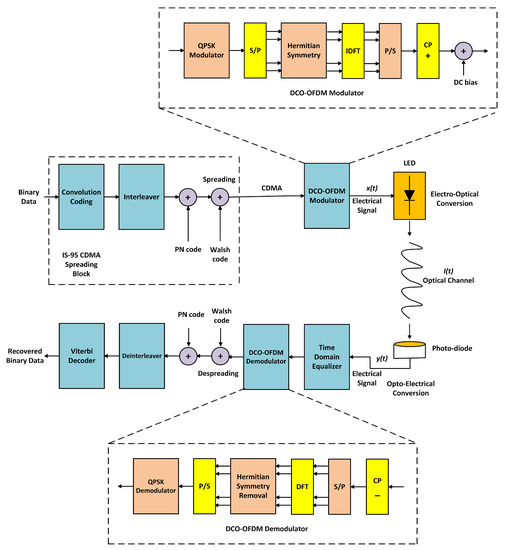
Figure 1.
Generic block diagram of DFT-based MC-CDMA system.
A PN code is a long code, created by 42-stage shift registers. This code is added to the interleaved data by using a modulo-2 operation. At this stage, the channel bit-rate 19.2 Kbps is not the final chip-rate. Next, the Walsh code is used for the purpose of channelization and spreading. It is an orthogonal code that offers orthogonality between different active users and it is generated via Hadamard matrix of dimension , where k stands for a positive integer and its value are 6. This means that there exists a set of 64 Walsh codes and from this set, only one code is used to spread the user data. The spreading operation is done by modulo-2 addition of Walsh code with privacy protected binary code. Each channel bit is changed into 64 Walsh chips, thus, yield a chip-rate of 1.2288 Mchips/s.
Next, the CDMA outcome leads to the DCO-OFDM modulator wherein the initial step is the mapping of spread bits onto constellation points. For this purpose, the Quadrature phase-shift keying (QPSK) scheme is used. Later, the QPSK modulated serial waveform is split into parallel waveforms to form the sub-carriers. Hermitian symmetry is placed on the sub-carriers, which switches the complex waveforms into real-valued ones. Afterward, 64 points IDFT block is employed that mutates the frequency-domain signal into time-domain. In the next phase, the parallel waveforms are converted back to the serial waveform and a CP is appended at the outset of the MC-CDMA symbol. The size of the CP is of the original signal. The time-domain MC-CDMA waveform ought to be both real and positive. Accordingly, a DC signal is summed up with the MC-CDMA waveform that converts the bipolar signals into unipolar ones. The final MC-CDMA output drives the LED transmitter so as to transforms the power of the input electrical signal into light intensity.
On the receiver side, PD translates the arriving optical power into the amplitude of an electrical signal. The system also includes the two sub-optimum linear time-domain detectors in the receiver design that tends to nullify the channel effects. These detectors are ZF and MMSE which will be discussed in Section 4. The equalized signal is applied to DCO-OFDM demodulator where the CP is wiped out and the serial data is separated into sub-carriers. Thereafter, the time-domain sub-carriers are transmuted back to frequency-domain using DFT operation and the Hermitian symmetry is also removed from the sub-carriers. These sub-carriers are then serially combined and after QPSK demodulation the data is input to a despreading block. In the last step, a deinterleaver and Viterbi decoder are used to decode the original data.
2.2. DWT Based Hybrid Multi-Carrier CDMA
The flaw of the DFT-MC-CDMA system is the overlapping of frequency responses of pulse shaping filters. This problem results in significant power leakage and Inter-carrier interference (ICI) between the sub-carriers. In [51], Sandberg et al. offered an impressive approach based on discrete wavelet multi-tone that improves the separation between the sub-carriers. Instead of sinusoids, the sub-carriers ensured the orthogonality by the aid of basis functions of the wavelet transform. These basis functions are built from the mother wavelet via operation of shifting and scaling. In wavelet studies, a signal to be processed is first decomposed into shifted and scaled versions that help in the separation of good and noisy part of the signal. This decomposed signal is then perfectly reconstructed with the help of filter banks that removes the noise from an originally transmitted signal without any performance degradation.
Before proceeding to the extensive insight on the decomposition and reconstruction phases of DWT/IDWT, it is essential to exhibit that the conventional DFT/IDFT blocks in Figure 1 are replaced with the DWT/IDWT blocks. Furthermore, the CP is also omitted in the wavelet-based MC-CDMA system design. The complete system model is illustrated in Figure 2.
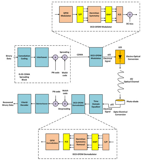
Figure 2.
Modeling of wavelet-based MC-CDMA system.
In [52], Mallet introduces a suitable method of computing the DWT/IDWT by employing the low pass (scaling) and high pass (wavelet) filters. These filters are also called Quadrature Mirror Filters (QMFs). Croisier first designs the QMFs in 1976 [53] and due to perfect reconstruction capability, they are widely used in multi-rate signal processing. The QMF filter bank comprises two stages i.e., analysis/decomposition and synthesis/reconstruction which will be explained shortly. The in-depth knowledge of QMF can be availed from [54,55,56]. However, here we quickly discuss the two conditions that the filters need to gratify for the restoration of the original signal. These conditions are formulated as [54]:
where and are the low pass filters, while and are the high pass filters, respectively. The first condition (Equation (1)) explains the criteria of aliasing free reconstruction while Equation (2) shows that the amplitude distortion possesses a unit value.
Figure 3a exemplifies the step-by-step procedure of level-3 Mallet tree analysis/decomposition in which the incoming signal carriers both high as well as low-frequency parts that range from . These frequency parts are separated by passing the samples of the incoming signal via a scaling and wavelet filter respectively. Hence, the resultant signal is the convolution sum between incoming samples and the filter’s impulse response. The filtered, low band decomposed signal contains the frequency parts which lie in the range from . Similarly, the filtered high band decomposed signal contains a frequency part that ranges from . This means that the filtering operation, reduce the resolution of the signal on half while keeping the scale constant [52].
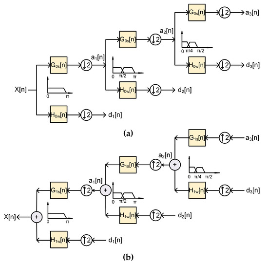
Figure 3.
Wavelet Transform using Mallet Tree: (a) Decomposition, (b) Reconstruction.
The filtered low band output is then downsampled by a factor 2. This is done because half of the signal frequencies are taken away due to which half of the signal samples are also abandoned. The output of the wavelet filter gives the detailed coefficients while the scaling filter gives approximate coefficients. In the next level, only approximate coefficients are passed through filter banks, which result in a further increase in frequency resolution. It is worth noting that the detailed coefficients have less information and therefore, these coefficients are discarded during the operation leaving no effects on the system [52]. At this level, scaling filter generates the output whose frequency components ranges from and wavelet filter generates the output whose frequency components lie in between . Through this way, the decomposition progression proceeds at the next level. In the last phase, the DWT of the original signal is acquired by concatenating all the coefficients, and , beginning with the last level of decomposition.
The procedure for inverse DWT is similar to the reconstruction of the original signal as shown in Figure 3b. In synthesis/reconstruction, at every level, the detailed and approximate coefficients are first upsampled by factor 2 and then passed to the low and high pass synthesis filter. The outcome of synthesis filters is then simply summed up to acquire the original signal. It is very crucial to draw the attention of the reader that the synthesis procedure should be extended for a similar number of levels for which the decomposition process was carried out [57].
2.3. DOWP Based Multi-Users Hybrid MC-CDMA System
The schematic diagram of multi-users hybrid MC-CDMA system is depicted in Figure 4; wherein the binary data streams from K users are initially fed into the DOWP-based CDMA block. The initial two stages (convolution coding and interleaving) in the CDMA block are just the same as outlined in Section 2.1; however, the difference is the incorporation of QPSK modulation block and the swapping of conventional Walsh code with the non-binary DOWP signature waveform. The binary data is first passed on to convolution encoder and then to the interleaver. After that the output of the interleaver will be mapped to complex symbols using QPSK modulation block. Next, with the help of unique non-binary signature waveforms, the complex data will be spread. During the next phase, the spread data from distinct users are incorporated to make a composite signal which is then fed into the DCO-OFDM modulation block. The block-by-block information on DCO-OFDM has previously been given in Section 2.1; however, it is essential to point out that here the sub-carriers of DCO-OFDM are modulating with the aid of IDWT block instead of IDFT. In the end, the output of DCO-OFDM will include data from all active users that will propagate through the free space optical channel.
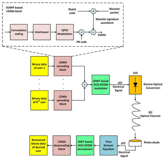
Figure 4.
DOWP Based Multi-users MC-CDMA System.
On the receiver side, the desired user will gather the optical signal by PD which will be the mixture of data signals from all potential users. The PD will perform the reverse conversion of optical signals to electrical signals. Following that the time-domain equalization along with the reverse MC-CDMA process is carried out to haul out the desired user data. To present insight relating to the generation of DOWP signature waveforms, it is instructive to begin the discussion with the basics of wavelet packets.
The wavelet packets are developed using upsampling followed by filtration of the impulses from the lower level nodes up to the root of a binary multi-level wavelet packet tree. The position and level of the specific node give an indication of the count for which upsampling and filtering operation has been carried out. On the other hand, the filter type used in the process also plays a vital role in the long-run process. Generally, two filters, low pass or high pass QMFs are commonly used for the operation. A binary level-3 wavelet packet tree, sufficient to produce 8 different wavelet packets is illustrated in Figure 5. This means to accommodate 64 users, a level-6 binary wavelet packet tree will be required. However, the wavelet packet tree generation complexity matures exponentially with an increase in the number of levels. Therefore, we confine to a level-3 binary wavelet packet tree structure and have to develop an algorithm that could adhere to the system’s demand i.e., 64 users. The length of the wavelet packet is directly proportional to the length of the incoming impulse signal. In an event where the incoming impulse has the length of 1, the binary tree generates the smallest wavelet packet with length equal to 8. On the other hand, filtering operation could fold the wavelet packets numerous times. The higher level filtration can cause more folding in the packets and therefore, a couple of wavelet packets from the distinct nodes may have created that turn out to be simply shifted versions of each other. Such wavelet packets are not an appropriate candidate for an asynchronous system.
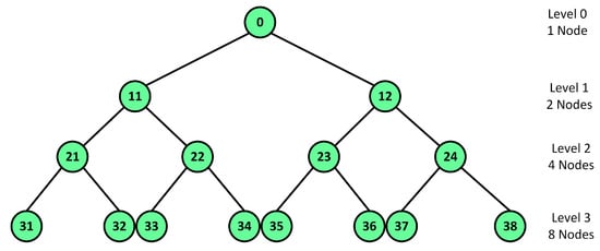
Figure 5.
Binary level-3 wavelet packet tree structure.
To design a system with 64 users, the total users are divided into 8 segments with 8 users each. These 8 segments are labeled as A through H. Now each segment of 8 users is combined with one Walsh code whose length is also 8 chips. Owing to the orthogonal property of Walsh codes, the 8 segments of users now constitute signature waveforms, which are also orthogonal to one another. 8 wavelet packets developed from a level-3 binary wavelet packet tree are also orthogonal to each other and these packets are labeled as 1 to 8. The product of 8 distinct wavelet packets with a single 8 chips Walsh code will produce doubly orthogonal signature waveforms. From this multiplication, 8 different possibilities are now available that allow us to match 8 distinct users to a single Walsh code. Hence, we are able to develop 64 distinct signature waveforms that are doubly orthogonal in nature.
Figure 6 represents the matrix for user segment A which depicts the mapping of 8 wavelet packets with 8 Walsh code chips. In a matrix, the digits 1 to 8 portray the indexes of wavelet packets. Each column of the matrix shows the correspondence of one time-slot with a Walsh code chip. In the same fashion, each row of the matrix gives a unique wavelet packet of 8 chips. The 8 rows of the matrix give 8 distinct packet waveforms in one user segment. Consider an example in which user 4 of the segment is designated by the 4th row. Therefore, the unique signature waveform for user 4 is developed by combining the wavelet packets and 5. In a similar fashion, signature waveforms for different users are also created with a different order; hence, the cross-correlation between the waveforms is reduced. In each time-slot, 8 distinct users are actually multiplied with 8 wavelet packets. This technique promises that the 8 user waveforms in the same segment are orthogonal to one another.
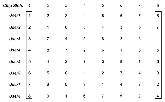
Figure 6.
Wavelet Packet Indexes of segment A containing 8 users.
Considering the fact that distinct users hold different wavelet packet waveforms in any of the given time-slots, it can be useful to signify the signal by means of permutation notations. With the use of above example, the 8 columns and 8 rows in the aforementioned matrix (Figure 6) denotes the different permutation as, . To ensure orthogonality, it is essential that in each column there are no repeated wavelet packet waveforms while this condition can be flexible for row entries. The signature waveforms created from the mapping matrix for segment A users are expressed as [45]:
where ⋯, ⋯ are 8 permutations of Kth user, and are the wavelet packets each of length 8. The mapping matrix for other segments remains similar to Figure 6. However, the only change is that the Walsh code chips vary for different segments. The generalized expression for doubly orthogonal signature waveforms for the Kth user in the jth group is given as [45]:
where ⋯ and is the jth Walsh code. Using the above-generalized algorithm, it can be depicted that the user 1 in segment A and segment B have same mapping order but the multiplication with two different orthogonal Walsh codes results in two doubly orthogonal signature waveforms.
3. VLC Channel Model for Multi-Users Communication
The proposed technique operates in a simplex transmission mode where the VLC transmitter broadcast the collective information of the users while silicon photo-diodes accept the optical signal. The generic diagram for multi-users VLC system is demonstrated in Figure 7. The dimensions of a typical room are 5 m × 5 m × 3 m and an LED transmitter is installed on the ceiling while the receiving photo-diodes (users) are supposed to be mobile or uniformly spread in the room. Moreover, each user equipment is located 1m above the floor. The number of LEDs within the transmitter is chosen in this manner that LEDs provide satisfactory illumination along with the communication [58,59].
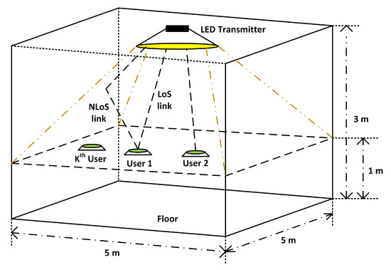
Figure 7.
VLC Channel for Multi-Users Environment.
Like RF channel, an indoor VLC channel also consists of two links, which are called the directed path or LoS, and the second link is diffused or NLoS [4]. Generally, only LoS link is evaluated as it holds almost 95% of total optical power at the receiver. However, if the LoS link is hindered by any object than NLoS link is used for the communication. The NLoS link provides the reflected optical power, which is of minute value. Both LoS and NLoS paths are given in Figure 7. The impulsive response of LoS link is expressed as [60,61,62,63]:
where shows the actual area of the PD, points out the vertical distance between LED and PD, represents the optical filter’s gain, illustrate the gain of the concentrator positioned on photo-diode, depicts the radiation incidence angle, and implies the angle with reference to transmitter. The aforesaid equation (Equation (5)) holds true only when is less than , where expresses the field of view (FOV) of the detector. The mathematical expression for NLoS link is exhibited as [64,65,66]:
where gives the number of reflections, exhibits the smaller area of the wall from which light signal reflects and points towards the detector, denotes the distance between transmitter and wall, shows the distance between wall and receiver, highlights the incidence angle before reflection, exhibits an incidence angle after reflection. The impulsive response of VLC channel is the sum of individual response of LoS and NLoS path which is indicated as [67]:
The output power of the optical signal can be portrayed as [59]:
where express the power emitted by LEDs, is the index of modulation and shows the transmitted signal. The optical power collected by the photo-diode is formulated as [68,69,70]:
where indicates the responsitivity of the photo-diode, is the transfer function of the multi-user VLC channel. With the help of the aforesaid equation (Equation (9)), the received optical power can be presented as a function of K users [59]:
The photo-diode received the optical power and generates a corresponding electrical signal whose power is computed as [59]:
where is an electrical signal which is derived from the photo-diode when DC components are blocked and it is given as [59]:
The SNR equation for the detected electrical signal is given as [71]:
where is the noise power. The complete details of can be seen in [71].
4. Multi-User Detection Techniques
The ongoing section is composed of a succinct discussion of multi-user detection techniques for an MC-CDMA system. The final modulated waveform of an MC-CDMA system is the composite signal of all the active users. The key challenge of the detection technique is to estimate the exact data of the specific user from the composite signal. In this connection, the early CDMA-based systems used a traditional detector called a matched filter [72,73,74]. This detector provides the optimum results only if the signature waveforms for the distinct users are orthogonal to the desired user code.
Meanwhile, a more optimal detector is suggested in [75] that attempt to take advantage of the log-likelihood function. However, this detector has also the disadvantage of excessive computational complexity that matures with the increasing number of active users, thereby, making the detector impractical. In this continuum, two sub-optimum linear detectors, ZF and MMSE were proposed in [76,77]. The linear detectors are accustomed in the receiver design to enjoy the most possible optimal benefits with an acceptable implementation. It is worth noting that the computational complexity associated with these detectors rises linearly with active users. The forthcoming subsections give the details of each detection technique.
4.1. Zero Forcing (ZF) Based Multi-User Detection
The ZF detector is the advancement of the traditional decorrelating detector. During the absence of noise, the ZF detector completely removes the negative effects of the channel. This is accomplished by the multiplication of the obtained signal with the inverse of the channel. However, the performance of the ZF detector is degraded due to noise addition. To develop the algorithm for ZF-based multi-user detection, consider a downlink MC-CDMA transmission in which the VLC channel response is similar for all active users. The mathematical modeling of the received signal is as follows [73,74]:
where R refers to the normalized cross-correlation matrix whose columns are made up of signature codes, exhibits a diagonal matrix containing the channel coefficients for each user, d shows the transmitted data symbols vector and z denote the additive-white Gaussian noise (AWGN). Generally, R is a not a diagonal matrix, therefore, it shows the MAI factor occurs due to non-zero cross-correlation. The linear filter of the ZF detector is calculated by setting the AWGN equal to zero in Equation (14). After that, by setting the required response to , the ZF linear filter is given by [74]. The ZF detector then performs the operation on the received signal y. The decorrelated vector signal, , at the output of the ZF detector is formulated as [73,74]:
It is worthy to state that at low the term becomes significant and the performance of ZF detector is poor.
4.2. MMSE Based Multi-User Detection
At low and moderate , the MMSE detector works well as compared to ZF since it lessens the error from the noise coupled with MAI [78]. The detector estimates the received signal vector by computing the mean square error between the original information and the soft output of a linear filter. Now, consider that x is the faded signal received at the detector and it is defined as , and W is the linear filter through which y is processed. By definition, the MMSE filter is calculated as [79]:
where denotes the complex conjugate. The linear filter of MMSE detector is formulated by multiplying the cross-correlation and the inverse of auto-correlation matrices for the vectors x and y. Mathematically,
The cross-correlation matrix of x and y is evaluated as [80]:
The auto-correlation matrix of y is given as [80]:
where is the unit power spectral density. By using Equations (19) and (21) in Equation (17), the MMSE filter is calculated as [73,79]:
The term indicates the inverse for a unit amplitude vector signal. Therefore, the MMSE filter is given as [73]:
5. Simulations Outcomes and Analysis
The effectiveness of the suggested indoor VLC system is assessing using computer-based numerical simulations. For comparisons, the simulation programs are formulated in MATLAB tool. The ongoing section is split up into four ensuing sections. The very first subsection delivers an extensive discussion on simulation setup. While the second section exhibits the simulation results of cross-correlation of different spreading waveforms. The third subsection reveals the outcomes and analysis of single and multi-users MC-CDMA-based VLC system in which DOWP signature waveforms are used for spreading. In the last subsection, computer-generated CCDF plots with detailed analysis of suggested and traditional MC-CDMA systems are also given.
5.1. Simulation Setup
The simulation setup of suggested indoor VLC system is demonstrated in Figure 7 where the room is vacant and its dimensions are 5 m × 5 m × 3 m. The LED transmitter comprises an array of 100 (10 × 10) LEDs. To make the simulations realistic, Luxeon LXR7-SW57 cool white LEDs are used that have the typical luminous flux of 1060 lm [81]. This luminous flux is completely competent to convene the demand of the indoor illumination. The correlated color temperature (CCT) and forward voltage of LXR7-SW57 LED is 5700 K and 11.2 V respectively, while the LED is available in a wider viewing angle of . The operating case temperature of the LED is C. It is worthy to report here that LXR7-SW57 LED is manufactured by using the phosphor component with a blue LED with a wavelength range of 445–460 nm [81]. The PD selected for the simulations is commercially accessible silicon pin diode Hamamatsu S6968 series. This PD is modeled into a clear plastic package with a surface lens of size 14 mm. The other specifications of S6968 PD are listed in Table 1 [82].

Table 1.
Parameters of Hamamatsu S6968 Si-PIN diode.
To make the system simple, it is presumed that the room is empty and an LED transmitter is mounted on the ceiling pointed in the downward direction. The vertical separation between LEDs and the user equipment is 2 m. All K users are uniformly spread in the vacant room and the MC-CDMA system is designed keeping in view that the VLC emitter and receiver are completely synchronized with each other. The transmission is conceded in the occurrence of both LoS and NLoS links. Moreover, for simulations, it is also considered that the NLoS link comprises three distinct light signals that are transmitted with irradiance angles , and respectively.
For multi-user communications, the LED transmitter is transmitting a mixture of MC-CDMA data from all active users and each user at the receiver end employs time-domain detector and specific signature waveform to recover its desired data. According to IS-95 standard, 184 bits are randomly generated on which MC-CDMA modulation is performed. The BER curves are obtained with the help of Monte Carlo simulations. The parameters compulsory for the simulations of proposed and conventional MC-CDMA-based multi-users VLC system are summarized in Table 2.
Table 2.
Simulation parameters for DFT and DWT-MC-CDMA systems.
Figure 8 exhibits the time-domain representation of the transmitted DWT-MC-CDMA signals for both single-user and multi-user communications. The x-axis represents the time, and the y-axis denotes the voltage level. It is noticeable from the single-user transmitted signal that the peak voltage level varies from −0.23 to 0.2 volts. Hence, a DC bias of around 0.23 volts is required to make the signal unipolar. The time-domain spectra for multi-users are also demonstrated in Figure 8; wherein the data signals from 16 distinct users are combined to form a composite signal. It is apparent from the spectra that at some points the signals are added constructively while at other points the signals may add destructively. With the increase in active users, the voltage level increases and now it varies from −1 to +1. Hence, to make the signal unipolar more DC biasing is required in comparison to single-user, which in turn increases the power of the system.
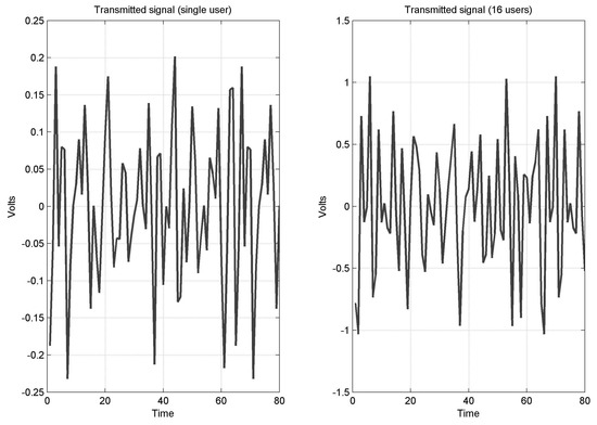
Figure 8.
Transmitted signal of suggested DWT-MC-CDMA system.
In Figure 9, the constellation diagrams for QPSK modem at different symbol-energy to noise power ratio values are demonstrated in signal space. The black asterisks (*) symbolize the transmitted QPSK symbols, and the red dots indicates the noise added received symbols. For the efficient recovery of these symbols two linear multi-user detectors, ZF and MMSE are also used in the receiver design. Figure 9a presents the constellation diagrams at = 0 dB. It is evident through the constellation diagrams that due to noise all four regions of signal space are not separate from each other and it is difficult for the detectors to recover the transmitted symbols. At = 16 dB, the variations caused by the noise are smaller than the previous case and the four regions of signal space are also separated. This enables the detectors in the efficient recovery of symbols. However, it is worth noting that the performance of ZF detector is still inferior when compared to MMSE.
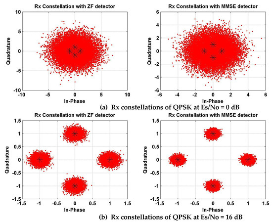
Figure 9.
Constellations diagrams for QPSK modem: (a) Rx constellations of QPSK at 0 dB, (b) Rx constellations of QPSK at 16 dB.
5.2. Cross-Correlation Results for DOWP
In this subsection, the cross-correlation results of DOWP are compared with the conventional spreading codes (PN and Walsh codes). For correlation, simulation programs are generated in MATLAB tool. The length of the spreading codes is selected to be 64 chips. The two PN waveforms are generated through shift registers while Walsh waveforms are obtained by selecting any two rows from the Hadamard matrix. The DOWP signature waveforms are generated by the multiplication of db4 wavelet with PN or Walsh code.
The correlation results between a pair of PN and Walsh sequences are shown in Figure 10, where it can be deduced that both PN and Walsh sequences lose orthogonality due to timing errors and hence, MAI occurs within the users. The correlation magnitude of Walsh codes is less than PN sequences; however, this value still not approaches to zero. The correlation of DOWP signature waveforms is also shown in Figure 10. The results of DOWP exhibits that the cross-correlation of PN sequences can be improved by the use of wavelets (PN-based DOWP); however, the performance of Walsh-based DOWP outperform all other spreading waveforms. Hence, the proposal of Walsh-based DOWP signature waveforms become a viable solution to be used as a spreading code in the multi-users MC-CDMA system.
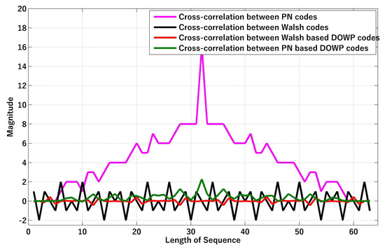
Figure 10.
Cross-correlation Results of DOWP, Walsh, and PN codes.
5.3. BER Performance Analysis of Proposed VLC System
We first analyze the effectiveness of single user DFT and DWT-based MC-CDMA system. The outcome for the single user communications is demonstrated in Figure 11. According to the simulation results, the BER performance of DFT-MC-CDMA is worst then DWT-MC-CDMA in general. When simulations are conducted with time-domain zero forcing equalizer then DWT-MC-CDMA attains a coding gain of about 1.4 dB as compared to DFT-MC-CDMA. However, this coding gain reduces to 1.3 dB for MMSE equalizer. We then analyze the performance between zero forcing and MMSE equalizers for both systems. The careful analysis of the results leads to an important fact that the MMSE equalizer outperforms zero forcing equalizer in both systems and achieves a coding gain of approximately 1.9 dB. This performance improvement is due to the Wiener estimator that de-correlates the desired symbols, ISI and noise terms. It is pertinent to state here that the computational complexity of both equalizers is similar.
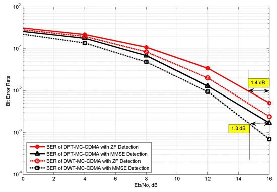
Figure 11.
Comparative analysis of DFT and DWT-based MC-CDMA system.
Next, we analyze the comparative analysis of proposed multi-users indoor VLC system. As we were well aware that DWT performs comparatively better than that of DFT, therefore, we only simulate DWT-based multi-users MC-CDMA system. For simulations, we consider 16 simultaneous active users and the spreading of user data is done by specific Walsh and DOWP signature waveforms. The user data at the receiver is estimated with both zero forcing and MMSE equalizer. The BER curves for user 16 are portrayed in Figure 12. According to the analysis of these results, our proposed DOWP-based DWT-MC-CDMA has best BER performance with respect to Walsh-based DWT-MC-CDMA technique. On comparing these results with Figure 11, it can be deduced that by increasing the number of active users MAI grows exponentially and the error performance of VLC system deteriorates. For both ZF and MMSE detection cases, the DOWP-based user 16 performs exactly 1.2 dB better than that of Walsh-based user 16. However, from both detection schemes, MMSE performs 1.8 dB superior to ZF.
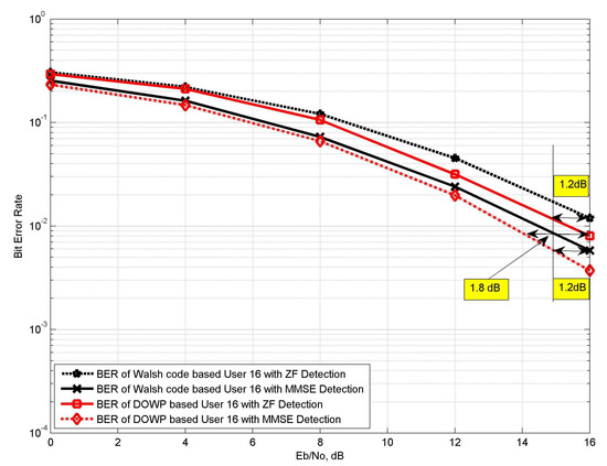
Figure 12.
BER Results of traditional and Proposed VLC Systems.
The next result (Figure 13) shows the graphs for number of users versus BER. The simulations are conducted for DWT-MC-CDMA system in which user data is spread by Walsh and DOWP signature waveforms. The is fixed at 16 dB and active users varies from 1 to 16. It is evident from the result that by increase the number of active users BER also increases. When active users reach the maximum number, i.e., 16, the BER for Walsh-based DWT-MC-CDMA is 0.0521 while for DOWP the BER is 0.0291. The result shows the significant decrease in error rate for DOWP-based DWT-MC-CDMA and hence the proposal of non-binary DOWP signature waveforms becomes a viable solution for multi-users communication system.
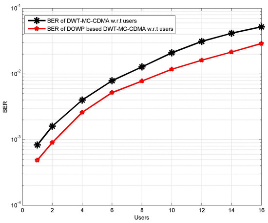
Figure 13.
BER versus number of users.
5.4. CCDF Based Effectiveness of DWT-MC-CDMA System
The present section also includes the PAPR analysis results for the conventional and proposed DWT-MC-CDMA-based indoor VLC system. Like OFDM, the transmitted waveform in the MC-CDMA system is the sum of parallel data streams, so its envelope also varies and causes PAPR. To quantify the PAPR, CCDF is one of the most important metrics and it is used because the modulating waveform is considered to be the random variable. The CCDF metric expresses the statistical characteristics of PAPR and it is referred as the probability that the PAPR surpass a fixed value i.e., [ > ], where is PAPR fix value. Figure 14 exhibits the CCDF graphs of DFT-MC-CDMA and DWT-MC-CDMA systems. At CCDF value of , the PAPR of DFT-MC-CDMA is 8.6 dB while for DWT-MC-CDMA system, the PAPR value is 6.7 dB. By comparing the PAPR values, it has been noticed that the DWT-MC-CDMA succeeds in achieving the PAPR reduction of about 1.9 dB.
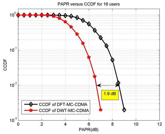
Figure 14.
CCDF-based performance comparison of DFT-MC-CDMA and DWT-MC-CDMA.
6. Conclusions
In this article, a novel indoor DWT-MC-CDMA-based VLC system for multiple users is designed and simulated. The DWT, due to its intrinsic time-frequency localization attributes, limits the ISI from the system and thus evades the usage of CP which is necessary for DFT-MC-CDMA. Meanwhile, it has been demonstrated through the numerical results that conventional spreading codes that include PN and Walsh codes are not perfectly orthogonal due to which MAI between active users arises which ultimately limits the capacity of the VLC system. The work has also targeted the issue of MAI and generates a non-binary DOWP signature waveform whose cross-correlation nearly approaches zero. The effectiveness of the suggested DOWP-based DWT-MC-CDMA system has been investigated in relation to the number of active users, detection techniques, required and BER. With the MMSE detection technique, the BER results of DOWP-based DWT-MC-CDMA system has shown a significant coding gain over Walsh-based DWT-MC-CDMA system. The usage of DOWP signature waveforms in CDMA-based VLC systems can certainly be the first step in the search of more suitable signature codes that can inhibit MAI, boost the user capacity and allow a low complexity system. Future work involves the physical deployment of the suggested system with the aid of cost-effective hardware tools.
Author Contributions
A.K. carried out the literature review for multi-users VLC system, formulates the simulation programs and wrote the paper. H.M.A. also carried out the literature review, and further develops the simulation programs, while K.I.K. assisted in the structure of the paper. S.A.-O. supervised the complete review process. Both K.M.S.H. and J.R. helped in the development of the figures and carried out vigorous review of the work.
Funding
This research received no external funding.
Acknowledgments
The authors would highly gratitude to the University of Lahore and Taif University for providing us the physical resources required to accomplish the experiments and writing of this manuscript.
Conflicts of Interest
The authors declare no conflict of interest.
References
- Martínez-Ciro, R.A.; López-Giraldo, F.E.; Betancur-Perez, A.F.; Luna-Rivera, J.M. Design and Implementation of a Multi-Colour Visible Light Communication System Based on a Light-to-Frequency Receiver. Photonics 2019, 6, 42. [Google Scholar] [CrossRef]
- Zvanovec, S.; Chvojka, P.; Haigh, P.A.; Ghassemlooy, Z. Visible light communications towards 5G. Radioengineering 2015, 24, 1–9. [Google Scholar] [CrossRef]
- Sarbazi, E.; Uysal, M. PHY layer performance evaluation of the IEEE 802.15. 7 visible light communication standard. In Proceedings of the 2013 2nd International Workshop on Optical Wireless Communications (IWOW), Newcastle upon Tyne, UK, 21 October 2013; pp. 35–39. [Google Scholar] [CrossRef]
- Ji, R.; Wang, S.; Liu, Q.; Lu, W. High-Speed Visible Light Communications: Enabling Technologies and State of the Art. Appl. Sci. 2018, 8, 589. [Google Scholar] [CrossRef]
- Elgala, H.; Mesleh, R.; Haas, H. Indoor optical wireless communication: Potential and state-of-the-art. IEEE Commun. Mag. 2011, 49. [Google Scholar] [CrossRef]
- Khadr, M.H.; Abd El Aziz, A.; Fayed, H.A.; Aly, M. Bandwidth and BER Improvement Employing a Pre-Equalization Circuit with White LED Arrays in a MISO VLC System. Appl. Sci. 2019, 9, 986. [Google Scholar] [CrossRef]
- Jovicic, A.; Li, J.; Richardson, T. Visible light communication: Opportunities, challenges and the path to market. IEEE Commun. Mag. 2013, 51, 26–32. [Google Scholar] [CrossRef]
- Boucouvalas, A.; Chatzimisios, P.; Ghassemlooy, Z.; Uysal, M.; Yiannopoulos, K. Standards for indoor optical wireless communications. IEEE Commun. Mag. 2015, 53, 24–31. [Google Scholar] [CrossRef]
- Pathak, P.H.; Feng, X.; Hu, P.; Mohapatra, P. Visible light communication, networking, and sensing: A survey, potential and challenges. IEEE Commun. Surv. Tutor. 2015, 17, 2047–2077. [Google Scholar] [CrossRef]
- Martinek, R.; Danys, L.; Jaros, R. Visible Light Communication System Based on Software Defined Radio: Performance Study of Intelligent Transportation and Indoor Applications. Electronics 2019, 8, 433. [Google Scholar] [CrossRef]
- Bawazir, S.S.; Sofotasios, P.C.; Muhaidat, S.; Al-Hammadi, Y.; Karagiannidis, G.K. Multiple Access for Visible Light Communications: Research Challenges and Future Trends. IEEE Access 2018, 6, 26167–26174. [Google Scholar] [CrossRef]
- Elgala, H.; Mesleh, R.; Haas, H.; Pricope, B. OFDM visible light wireless communication based on white LEDs. In Proceedings of the 2007 IEEE 65th Vehicular Technology Conference—VTC2007-Spring, Dublin, Ireland, 22–25 April 2007; pp. 2185–2189. [Google Scholar] [CrossRef]
- Guzmán, B.G.; Jiménez, V.P.G.; Aguayo-Torres, M.C.; Haas, H.; Hanzo, L. Downlink Performance of Optical OFDM in Outdoor Visible Light Communication. IEEE Access 2018, 6, 76854–76866. [Google Scholar] [CrossRef]
- Haigh, P.A.; Ghassemlooy, Z.; Rajbhandari, S.; Papakonstantinou, I.; Popoola, W. Visible light communications: 170 Mb/s using an artificial neural network equalizer in a low bandwidth white light configuration. J. Lightwave Technol. 2014, 32, 1807–1813. [Google Scholar] [CrossRef]
- Basnayaka, D.A.; Haas, H. Hybrid RF and VLC systems: Improving user data rate performance of VLC systems. In Proceedings of the 2015 IEEE 81st Vehicular Technology Conference (VTC Spring), Glasgow, UK, 11–14 May 2015; pp. 1–5. [Google Scholar] [CrossRef]
- Yoo, J.H.; Jung, S.Y. Multi-coded variable PPM with level cutting for high data rate visible light communications. In Proceedings of the 2012 18th Asia-Pacific Conference on Communications (APCC), Jeju Island, Korea, 15–17 October 2012; pp. 703–708. [Google Scholar] [CrossRef]
- Narmanlioglu, O.; Kizilirmak, R.C.; Uysal, M. Performance of OFDM-based adaptive visible light communications. In Proceedings of the 2016 IEEE 10th International Conference on Application of Information and Communication Technologies (AICT), Baku, Azerbaijan, 12–14 October 2016; pp. 1–4. [Google Scholar] [CrossRef]
- Wu, L.; Zhang, Z.; Dang, J.; Liu, H. Adaptive modulation schemes for visible light communications. J. Lightwave Technol. 2014, 33, 117–125. [Google Scholar] [CrossRef]
- Berenguer, P.W.; Jungnickel, V.; Fischer, J.K. The benefit of frequency-selective rate adaptation for optical wireless communications. In Proceedings of the 2016 10th International Symposium on Communication Systems, Networks and Digital Signal Processing (CSNDSP), Prague, Czech Republic, 20–22 July 2016; pp. 1–6. [Google Scholar] [CrossRef]
- Fath, T.; Haas, H. Performance comparison of MIMO techniques for optical wireless communications in indoor environments. IEEE Trans. Commun. 2012, 61, 733–742. [Google Scholar] [CrossRef]
- Sung, J.Y.; Yeh, C.H.; Chow, C.W.; Lin, W.F.; Liu, Y. Orthogonal frequency-division multiplexing access (OFDMA) based wireless visible light communication (VLC) system. Opt. Commun. 2015, 355, 261–268. [Google Scholar] [CrossRef]
- Wang, Q.; Wang, Z.; Dai, L. Multiuser MIMO-OFDM for visible light communications. IEEE Photonics J. 2015, 7, 1–11. [Google Scholar] [CrossRef]
- Al-Ahmadi, S.; Maraqa, O.; Uysal, M.; Sait, S.M. Multi-user visible light communications: State-of-the-art and future directions. IEEE Access 2018, 6, 70555–70571. [Google Scholar] [CrossRef]
- Tsonev, D.; Islim, M.S.; Haas, H. OFDM-based visible light communications. In Optical Wireless Communications; Springer: Cham, Switzerland, 2016; pp. 255–298. [Google Scholar] [CrossRef]
- Armstrong, J. OFDM for optical communications. J. Lightwave Technol. 2009, 27, 189–204. [Google Scholar] [CrossRef]
- Dissanayake, S.D.; Armstrong, J. Comparison of aco-ofdm, dco-ofdm and ado-ofdm in im/dd systems. J. Lightwave Technol. 2013, 31, 1063–1072. [Google Scholar] [CrossRef]
- Giacoumidis, E.; Tsokanos, A.; Mouchos, C.; Zardas, G.; Alves, C.; Wei, J.; Tang, J.; Gosset, C.; Jaouen, Y.; Tomkos, I. Extensive comparisons of optical fast-OFDM and conventional optical OFDM for local and access networks. J. Opt. Commun. Netw. 2012, 4, 724–733. [Google Scholar] [CrossRef]
- Wang, Z.; Wang, Q.; Huang, W.; Xu, Z. Visible Light Communications: Modulation and Signal Processing; John Wiley & Sons: Hoboken, NJ, USA, 2017. [Google Scholar]
- Wang, P.; Xiao, J.; Li, P. Comparison of orthogonal and non-orthogonal approaches to future wireless cellular systems. IEEE Veh. Technol. Mag. 2006, 1, 4–11. [Google Scholar] [CrossRef]
- Marshoud, H.; Sofotasios, P.C.; Muhaidat, S.; Karagiannidis, G.K. Multi-user techniques in visible light communications: A survey. In Proceedings of the 2016 International Conference on Advanced Communication Systems and Information Security (ACOSIS), Marrakesh, Morocco, 17–19 October 2016; pp. 1–6. [Google Scholar] [CrossRef]
- Kazemi, H.; Haas, H. Downlink cooperation with fractional frequency reuse in DCO-OFDMA optical attocell networks. In Proceedings of the 2016 IEEE International Conference on Communications (ICC), Kuala Lumpur, Malaysia, 22–27 May 2016; pp. 1–6. [Google Scholar] [CrossRef]
- Lin, B.; Tang, X.; Yang, H.; Ghassemlooy, Z.; Zhang, S.; Li, Y.; Lin, C. Experimental demonstration of IFDMA for uplink visible light communication. IEEE Photonics Technol. Lett. 2016, 28, 2218–2220. [Google Scholar] [CrossRef]
- Brannstrom, F.; Aulin, T.M.; Rasmussen, L.K. Iterative detectors for trellis-code multiple-access. IEEE Trans. Commun. 2002, 50, 1478–1485. [Google Scholar] [CrossRef]
- Gilhousen, K.S.; Jacobs, I.M.; Padovani, R.; Viterbi, A.J.; Weaver, L.A.; Wheatley, C.E. On the capacity of a cellular CDMA system. IEEE Trans. Veh. Technol. 1991, 40, 303–312. [Google Scholar] [CrossRef]
- Dang, J.; Zhang, Z. Comparison of optical OFDM-IDMA and optical OFDMA for uplink visible light communications. In Proceedings of the 2012 International Conference on Wireless Communications and Signal Processing (WCSP), Huangshan, China, 25–27 October 2012; pp. 1–6. [Google Scholar] [CrossRef]
- Noshad, M.; Brandt-Pearce, M. High-speed visible light indoor networks based on optical orthogonal codes and combinatorial designs. In Proceedings of the 2013 IEEE Global Communications Conference (GLOBECOM), Atlanta, GA, USA, 9–13 December 2013; pp. 2436–2441. [Google Scholar] [CrossRef]
- Guerra-Medina, M.F.; Rojas-Guillama, B.; González, O.; Martín-González, J.A.; Poves, E.; López-Hernández, F.J. Experimental optical code-division multiple access system for visible light communications. In Proceedings of the 2011 Wireless Telecommunications Symposium (WTS), New York, NY, USA, 13–15 April 2011; pp. 1–6. [Google Scholar] [CrossRef]
- Guerra-Medina, M.; Gonzalez, O.; Rojas-Guillama, B.; Martin-Gonzalez, J.; Delgado, F.; Rabadan, J. Ethernet-OCDMA system for multi-user visible light communications. Electron. Lett. 2012, 48, 227–228. [Google Scholar] [CrossRef]
- Shoreh, M.H.; Fallahpour, A.; Salehi, J.A. Design concepts and performance analysis of multicarrier CDMA for indoor visible light communications. J. Opt. Commun. Netw. 2015, 7, 554–562. [Google Scholar] [CrossRef]
- Hara, S.; Prasad, R. Overview of multicarrier CDMA. IEEE Commun. Mag. 1997, 35, 126–133. [Google Scholar] [CrossRef]
- Baig, S.; Asif, H.M.; Umer, T.; Mumtaz, S.; Shafiq, M.; Choi, J.G. High Data Rate Discrete Wavelet Transform-Based PLC-VLC Design for 5G Communication Systems. IEEE Access 2018, 6, 52490–52499. [Google Scholar] [CrossRef]
- Wu, Z.Y.; Gao, Y.L.; Wang, Z.K.; You, C.; Yang, C.; Luo, C.; Wang, J. Optimized DFT-spread OFDM based visible light communications with multiple lighting sources. Opt. Express 2017, 25, 26468–26482. [Google Scholar] [CrossRef]
- Chen, Y.; Yang, C.; Yang, Q.; Liu, W.; Li, C.; Zhang, D. Wavelet transform-OFDM in indoor visible light communication. In Optical Fiber Communication Conference; Optical Society of America: Washington, DC, USA, 2015. [Google Scholar]
- Bulakci, O.; Schuster, M.; Bunge, C.A.; Spinnler, B.; Hanik, N. Wavelet transform based optical OFDM. In Proceedings of the 2009 Conference on Optical Fiber Communication—Incudes Post Deadline Papers, San Diego, CA, USA, 22–26 March 2009; pp. 1–3. [Google Scholar] [CrossRef]
- Zhang, H.; Fan, H.H.; Lindsey, A. Over-loaded DS-CDMA system waveform design using doubly orthogonal wavelet packets. In Proceedings of the IEEE 54th Vehicular Technology Conference—VTC Fall 2001. Proceedings (Cat. No.01CH37211), Atlantic City, NJ, USA, 7–11 October 2001; Volume 2, pp. 1025–1029. [Google Scholar] [CrossRef]
- Hetling, K.; Medley, M.; Saulnier, G.; Das, P. A PR-QMF (wavelet) based spread spectrum communications system. In Proceedings of the Military Communications Conference (MILCOM’94)—Conference Record, Fort Monmouth, NJ, USA, 2–5 October 1994; pp. 760–764. [Google Scholar] [CrossRef]
- Hetling, K.; Saulnier, G.; Das, P. Spreading codes for wireless spread spectrum communications. In Proceedings of the ICC/SUPERCOMM ’96—International Conference on Communications, Dallas, TX, USA, 23–27 June 1996; Volume 1, pp. 68–72. [Google Scholar] [CrossRef]
- Learned, R.E.; Willsky, A.S.; Boroson, D.M. Low complexity optimal joint detection for oversaturated multiple access communications. IEEE Trans. Signal Process. 1997, 45, 113–123. [Google Scholar] [CrossRef]
- Lindsey, A.R. Wavelet packet modulation for orthogonally multiplexed communication. IEEE Trans. Signal Process. 1997, 45, 1336–1339. [Google Scholar] [CrossRef]
- Sklar, B. Digital Communications; Prentice Hall: Upper Saddle River, NJ, USA, 2001; Volume 2. [Google Scholar]
- Sandberg, S.D.; Tzannes, M.A. Overlapped discrete multitone modulation for high speed copper wire communications. IEEE J. Sel. Areas Commun. 1995, 13, 1571–1585. [Google Scholar] [CrossRef]
- Mallat, S. A Wavelet Tour of Signal Processing; Elsevier: Amsterdam, The Netherlands, 1999. [Google Scholar]
- Croisier, A. Perfect channel splitting by use of interpolation/decimation/tree decomposition techniques. In Proceedings of the International Symposium on Information Circuis and Systems, Patras, Greece, 17–21 June 1976. [Google Scholar] [CrossRef]
- Vaidyanathan, P.P. Multirate Systems and Filter Banks; Pearson Education: New Delhi, India, 1993. [Google Scholar]
- Esteban, D.; Galand, C. Application of quadrature mirror filters to split band voice coding schemes. In Proceedings of the IEEE International Conference on Acoustics, Speech, and Signal Processing (ICASSP’77), Hartford, CT, USA, 9–11 May 1977; Volume 2, pp. 191–195. [Google Scholar] [CrossRef]
- Agrawal, S.; Sahu, O. Two-channel quadrature mirror filter bank: An overview. ISRN Signal Process. 2013, 2013. [Google Scholar] [CrossRef]
- Khan, A.; Arif, A.; Nawaz, T.; Baig, S. Walsh Hadamard transform based transceiver design for SC-FDMA with discrete wavelet transform. China Commun. 2017, 14, 193–206. [Google Scholar] [CrossRef]
- Pratama, Y.S.M.; Choi, K.W. Bandwidth Aggregation Protocol and Throughput-Optimal Scheduler for Hybrid RF and Visible Light Communication Systems. IEEE Access 2018, 6, 32173–32187. [Google Scholar] [CrossRef]
- Sewaiwar, A.; Tiwari, S.V.; Chung, Y.H. Smart LED allocation scheme for efficient multiuser visible light communication networks. Opt. Express 2015, 23, 13015–13024. [Google Scholar] [CrossRef] [PubMed]
- Niaz, M.T.; Imdad, F.; Kim, H.S. Power Consumption Efficiency Evaluation of Multi-User Full-Duplex Visible Light Communication Systems for Smart Home Technologies. Energies 2017, 10, 254. [Google Scholar] [CrossRef]
- Marin-Garcia, I.; Guerra, V.; Perez-Jimenez, R. Study and validation of eavesdropping scenarios over a visible light communication channel. Sensors 2017, 17, 2687. [Google Scholar] [CrossRef]
- Yu, Z.; Baxley, R.J.; Zhou, G.T. Multi-user MISO broadcasting for indoor visible light communication. In Proceedings of the International Conference on Acoustics, Speech and Signal Processing (ICASSP), Vancouver, BC, Canada, 26–31 May 2013; pp. 4849–4853. [Google Scholar] [CrossRef]
- Sifaou, H.; Kammoun, A.; Park, K.H.; Alouini, M.S. Robust Transceivers Design for Multi-Stream Multi-User MIMO Visible Light Communication. IEEE Access 2017, 5, 26387–26399. [Google Scholar] [CrossRef]
- Chen, C.; Basnayaka, D.A.; Wu, X.; Haas, H. Efficient Analytical Calculation of Non-Line-of-Sight Channel Impulse Response in Visible Light Communications. J. Lightwave Technol. 2018, 36, 1666–1682. [Google Scholar] [CrossRef]
- Assabir, A.; Elmhamdi, J.; Hammouch, A.; Belhaf, L.; Akherraz, A. The effects of the field of view and reflections on the optical wireless channel. In Proceedings of the International Conference on Electrical and Information Technologies (ICEIT), Rabat, Morocco, 15–18 November 2017; pp. 1–5. [Google Scholar] [CrossRef]
- Bykhovsky, D.; Arnon, S. Multiple access resource allocation in visible light communication systems. J. Lightwave Technol. 2014, 32, 1594–1600. [Google Scholar] [CrossRef]
- Ghassemlooy, Z.; Popoola, W.; Rajbhandari, S. Optical Wireless Communications: System and Channel Modelling With Matlab®; CRC Press: Boca Raton, FL, USA, 2012. [Google Scholar]
- Do, T.H.; Yoo, M. Received power and SNR optimization for visible light communication system. In Proceedings of the 4th International Conference on Ubiquitous and Future Networks (ICUFN), Phuket, Thailand, 4–6 July 2012; pp. 6–7. [Google Scholar] [CrossRef]
- Ganjian, T.; Baghersalimi, G.; Ghassemlooy, Z. Performance evaluation of the received power based on the transmitter position in a visible light communications system. In Proceedings of the Iranian Conference on Electrical Engineering (ICEE), Tehran, Iran, 2–4 May 2017; pp. 1763–1768. [Google Scholar] [CrossRef]
- Hou, Y.; Xiao, S.; Zheng, H.; Hu, W. Multiple access scheme based on block encoding time division multiplexing in an indoor positioning system using visible light. J. Opt. Commun. Netw. 2015, 7, 489–495. [Google Scholar] [CrossRef]
- Komine, T.; Nakagawa, M. Fundamental analysis for visible-light communication system using LED lights. IEEE Trans. Consum. Electron. 2004, 50, 100–107. [Google Scholar] [CrossRef]
- Wang, X.; Lu, W.S.; Antoniou, A. Multiuser detection for multiple-access communications using wavelet-packet transforms. In Proceedings of the Pacific Rim Conference on Communications, Computers and Signal Processing (PACRIM), 10 Years Networking the Pacific Rim, 1987–1997, Victoria, BC, Canada, 20–22 August 1997; Volume 2, pp. 607–610. [Google Scholar] [CrossRef]
- Kühn, V.; Böhnke, R.; Kammeyer, K.D. Multi-user detection in multicarrier-CDMA systems. e&i Elektrotechnik und Informationstechnik 2002, 119, 395–402. [Google Scholar] [CrossRef]
- Moshavi, S. Multi-user detection for DS-CDMA communications. IEEE Commun. Mag. 1996, 34, 124–136. [Google Scholar] [CrossRef]
- Verdii, S. Minimum probability of error for asynchronous Gaussian multiple-access channels. IEEE Trans. Inf. Theory 1986, 32, 85–96. [Google Scholar] [CrossRef]
- Klein, A.; Kaleh, G.K.; Baier, P.W. Zero forcing and minimum mean-square-error equalization for multiuser detection in code-division multiple-access channels. IEEE Trans. Veh. Technol. 1996, 45, 276–287. [Google Scholar] [CrossRef]
- Ueng, F.B.; Wang, H.F.; Chang, R.; Jeng, L.D. Zero forcing and minimum mean square error equalization for OFDM-CDMA multiuser detection in multipath fading channels. In Proceedings of the International Symposium on Intelligent Signal Processing and Communications, Tottori, Japan, 12–15 December 2006; pp. 505–509. [Google Scholar] [CrossRef]
- Poor, H.V.; Verdú, S. Probability of error in MMSE multiuser detection. IEEE Trans. Inf. Theory 1997, 43, 858–871. [Google Scholar] [CrossRef]
- Uzmi, Z.A. Simplified Multiuser Detection for CDMA Systems. Ph.D. Thesis, Stanford University, Stanford, CA, USA, 2002. [Google Scholar]
- Kailath, T.; Sayed, A.H.; Hassibi, B. Linear Estimation; Number Book; Prentice Hall: Upper Saddle River, NJ, USA, 2000. [Google Scholar]
- LUXEON. DS103 LUXEON M Product Datasheet-Lumileds. 2015. Available online: https://www.lumileds.com/uploads/354/DS103-pdf (accessed on 29 March 2019).
- Photonics, H. Si PIN Photodiode. 2017. Available online: https://www.hamamatsu.com/resources/pdf/ssd/s6801_etc_kpin1046e.pdf (accessed on 29 March 2019).


© 2019 by the authors. Licensee MDPI, Basel, Switzerland. This article is an open access article distributed under the terms and conditions of the Creative Commons Attribution (CC BY) license (http://creativecommons.org/licenses/by/4.0/).