


Abstract
We designed a kind of new vortex beam generator based on a planar all-dielectric metamaterial in the mid-infrared band. The height of this generator remains constant in the plane, and the effective refractive index increases gradually in the azimuthal direction which depends on subwavelength aperture columns with gradual diameters in the dielectric flat plate. Two types of vortex beam generators including transmissive- and reflective-type generators are designed where the thickness of the latter is half of the former. Simulation results show that both vortex beam generators successfully produce mid-infrared vortex beams with a topological charge number of one. This planar vortex beam generator based on a dielectric metamaterial has the advantages of simple structure, easy processing and low optical absorption.
1. Introduction
Vortices are a phenomenon in our daily life; some of them are common, such as whirlpools, tornadoes, hurricanes, etc. Others are less easily noticed, such as the amphibious points of tidal waves in the ocean. The intensity of vector fields of all these phenomena is zero at the center of the vortex and rotates around it. In optics, we refer to beams that possess similar phenomena as vortex beams. Optical Vortices (OVs) are beams of light that carry orbital angular momentum and have a spiral-shaped wavefront phase distribution [1,2,3,4,5,6]. Vortex beams are widely studied due to their unique optical properties and additional degrees of freedom for optical manipulation, and are used in many research fields, including astronomical observation [7,8], quantum simulation [9,10], particle capture [11,12], optical communication [13,14], processing of micro and nano structures [15,16,17], information coding [18], etc.
In recent years, studies on the generation of vortex beams in the visible [19], near-infrared [20,21] and microwave bands [22] have been widely reported. The vortex beam generators developed in these studies can be applied in communication systems as well as in spectral imaging. In addition to vortex beams in the above wavelength range, mid-infrared vortex beams also have promising applications in organic material processing [23], super-resolution molecular spectroscopy [24], navigation communications [25], biomedicine, etc. Several approaches to generating vortex beams in the mid-infrared band have been investigated, such as using optical parametric oscillators [26] or super-surfaces [27], which still present challenges in terms of reducing device size, fabrication complexity and metal loss. Therefore, it is of interest to design a miniaturized, easily processed and integrated mid-infrared vortex beam generator.
The conventional spiral phase plate has a spiral surface, and when the incident beam passes through the spiral phase plate, the change in the transmitted beam range is different, and thus the change in phase is also different, generating a vortex beam. However, this method of generating a vortex beam by modulating the incident beam through the spatial variation in thickness inevitably introduces disadvantages such as complex structure and processing difficulties. Therefore, we designed a kind of new vortex beam generator in the mid-infrared band to produce a vortex beam by modulating the incident light through the spatial variation in gradual refractive index, which is based on a planar all-dielectric metamaterial.
2. Structural Design of Transmissive Metamaterial Vortex Phase Plate
Unlike the conventional spiral phase plate, the vortex phase plate based on an all-dielectric metamaterial in this paper has a planar structure, whose height remains constant in the plane and the effective refractive index of the metamaterial increases gradually in the azimuthal direction. The phase plate has a refractive index difference in the azimuthal direction in the plane, which in turn produces a phase difference in the incident beam and achieves the same effect as the conventional spiral phase plate, producing a vortex beam.
We divide the transmissive metamaterial vortex phase plate into eight sectors uniformly in a clockwise direction along the plane; each sector consists of a subwavelength perforated cell lattice periodically arranged, and the gradient of the refractive index can be set by adjusting the size of the aperture on each sector. The basic cell size on the phase plate is subwavelength, which is one-fifth of the working wavelength, i.e., d = 0.8 . The phase plate material is Si with refractive index and thickness h = 2.272 .
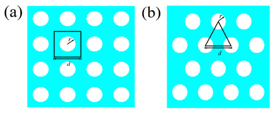
Next, the effective refractive index of the phase plate is analyzed by Effective Media Theory (EMT). The basic principle of EMT is to calculate the weighted average of optical parameters of dielectric materials based on the occupancy ratio of various media in space. This theory can calculate the effective refractive index for periodic subwavelength micro and nano structures, such as laminar structures [28], rectangular gratings [29], and nanopore structures [30]. The phase plate of superstructured material designed in this section has two types of unit lattice, i.e., square lattice and triangular lattice. So, the refractive index of the dielectric material can be changed by punching circular holes in the unit lattice, and the two types of perforated unit lattice arrays are shown in Figure 1a and Figure 1b, respectively, in which one part of the unit lattice is air and the other part is silicon material.
Figure 1.
Schematic diagram of the two-dimensional structure of the lattice array of perforated cells. (a,b) show a square lattice array and a triangular lattice array of circular holes, respectively.
The equivalent refractive indices of the two perforated unitary lattices are calculated as follows:
where is the equivalent refractive index, denotes the air hole filling ratio, and and are the effective permittivities of the phase plate and air, respectively. is the equivalent permittivity of the cell structure after perforation. For the two types of cell lattice with circular holes, the formula for the air hole filling rate is different. The formula for the air hole filling rate of a square lattice is as follows [31,32]:
The equation for the air pore filling rate of a triangular lattice is as follows [33,34]:
where r is the radius of the circular air hole and d is the size of the lattice constant of the unit structure. The equivalent refractive index of the perforated cell can be obtained by combining Equations (1) and (2):
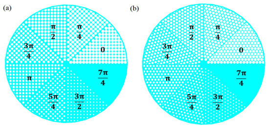
where and are the effective refractive indices of the silicon-based material and air, respectively. According to Equation (5), the hole size of the unit structure of each sector of the phase plate is obtained by inverse solution under the condition that the effective refractive indices of the eight sectors are known. The two-dimensional planes of the perforated unit structure on the eight sectors of the phase plate of superconformal materials designed using a square lattice with circular holes are shown in Figure 2, and the corresponding aperture parameters and the equivalent refractive indices of different sectors are shown in Table 1.
Figure 2.
Two-dimensional plan view of eight sector punching units.
Table 1.
Hole radii and equivalent refractive indices in a square lattice.
The two-dimensional planes of the perforated cell structure on the eight sectors of the metamaterial phase plate designed using the circular hole triangular lattice are shown in Figure 3, and the corresponding aperture parameters and the equivalent refractive indices of the different sectors are shown in Table 2.
Figure 3.
Two-dimensional plan view of the eight sector perforated cells.
Table 2.
Hole radii and equivalent refractive indices in the triangular lattice.
Based on the spatial distribution of the effective refractive indices on the transmissive phase plate obtained for the square lattice and triangular lattice design, the phase plate causes the phase delay of the incident beam to be
where is the refractive index difference between each sector, and the size of the phase plate delay depends on . According to Equation (6), the eight sectors on the two phase plates produce phase delays of 0, , , , , , , and , respectively, and two adjacent sectors are phase-separated by .
Eight sectors with different hole radii are arranged clockwise along the plane of the phase plate, covering the amount of phase change from ; then, the delayed modulation of the incident electromagnetic wave’s full phase can be achieved, and the specific hole size on the phase plate is arranged as shown in Figure 4.
Figure 4.
Phase delay and hole arrangement of eight sectors. (a) Square lattice arrangement; (b) triangular lattice arrangement.
3. Simulation Results of Transmissive Metamaterial Vortex Phase Plate
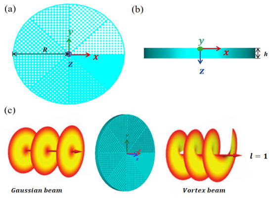
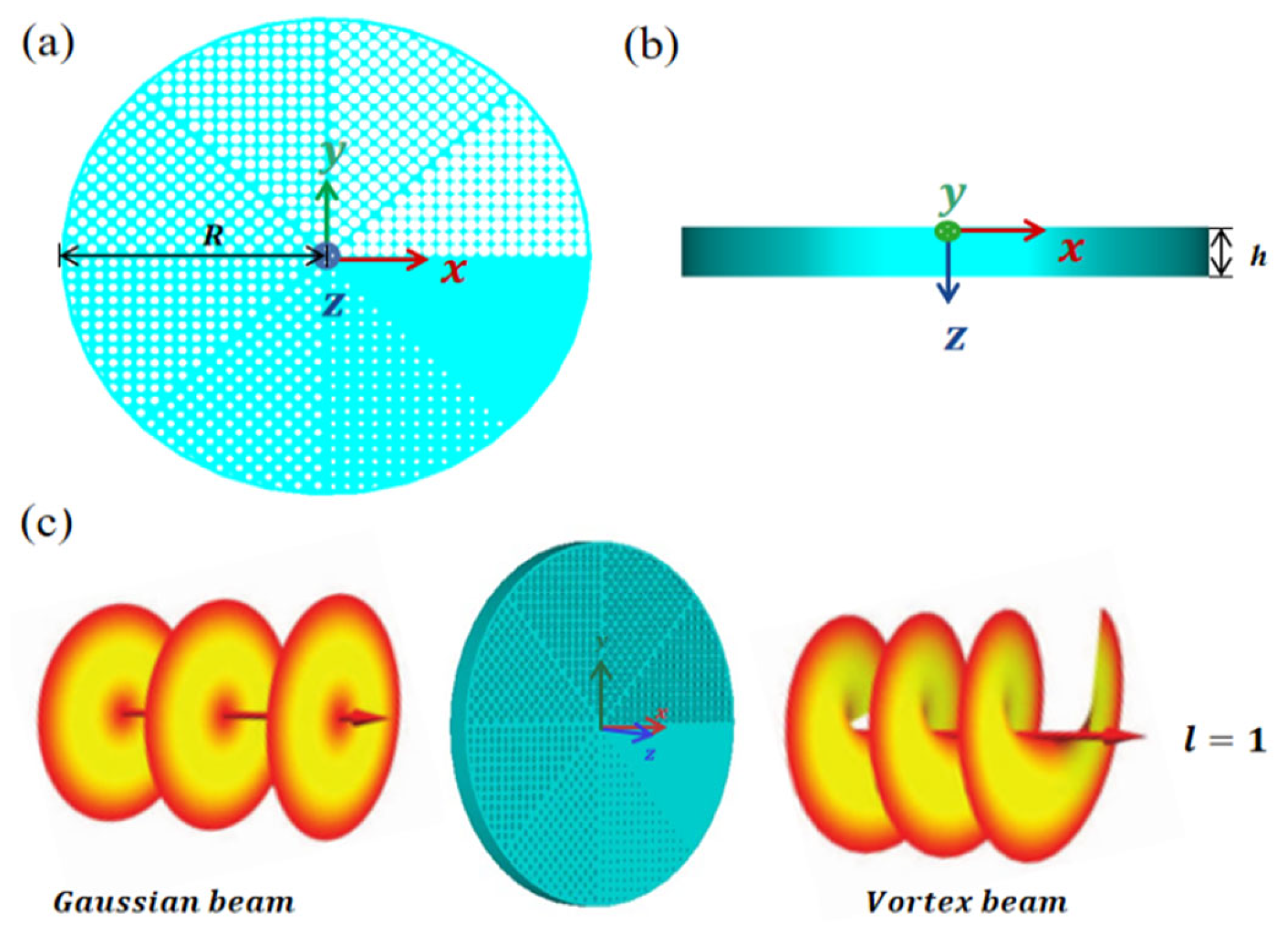
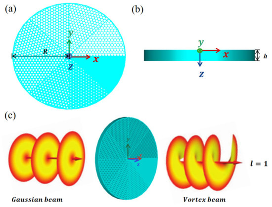
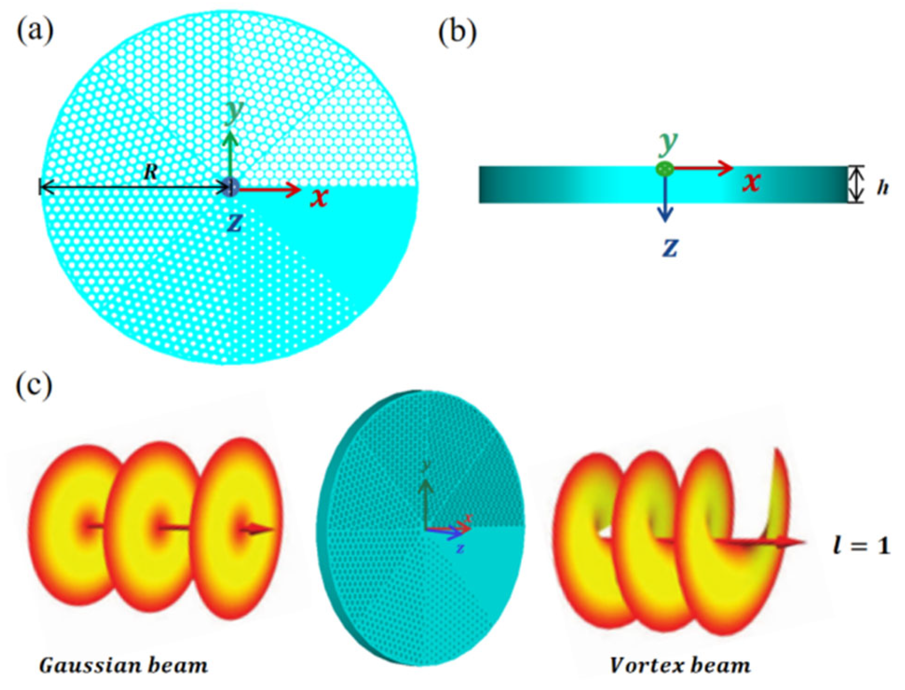
The top and side views of the structure of the transmissive metamaterial vortex phase plate designed using a square lattice through circular holes are shown in Figure 5a,b, with the phase plate radius R = 15.3 and thickness 2.272 . The phase plate is simulated by using CST electromagnetic field simulation software, and the excitation source is a Gaussian beam with a wavelength of , which is incident at a distance of 20 mm from the phase plate along the positive z-axis. The refractive index on the phase plate is distributed counterclockwise from small to large, and the phase plate is placed at the beam waist of the Gaussian beam. Figure 5c shows the schematic diagram of the transmissive metamaterial vortex phase plate under the incidence of the Gaussian beam.
Figure 5.
Schematic diagram of the vortex phase plate of a square lattice transmissive metamaterial. (a) Top view of the phase plate; (b) side view of the phase plate; (c) schematic diagram of the Gaussian beam incident on the phase plate.
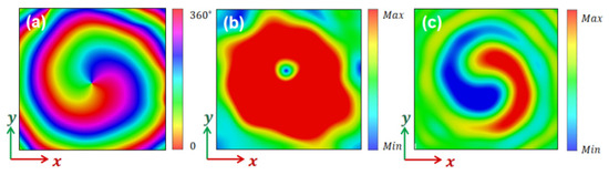
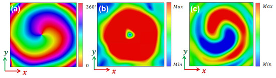
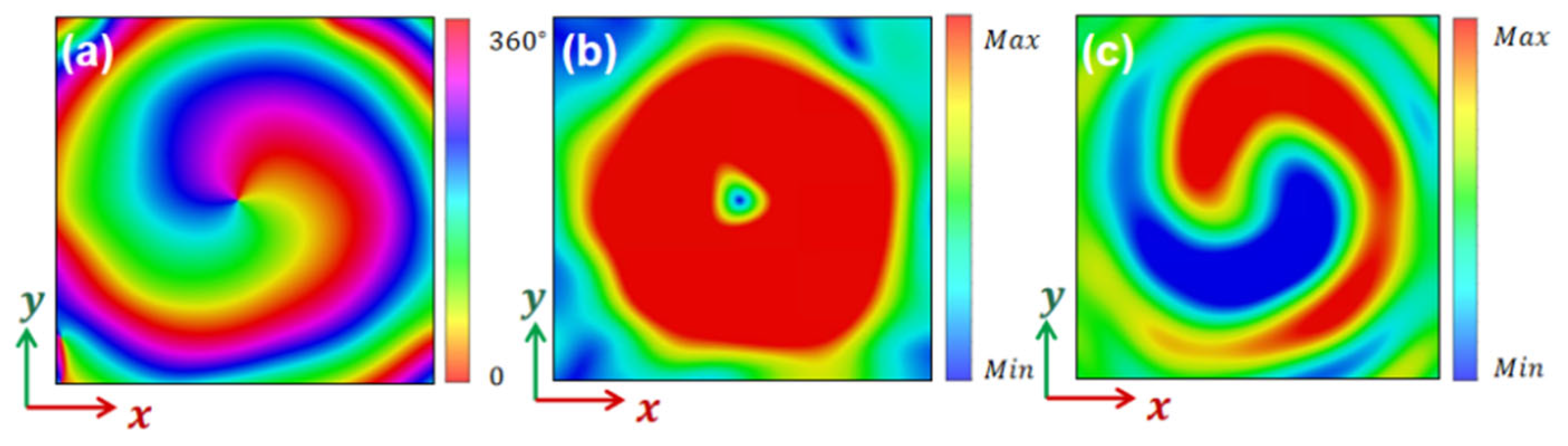
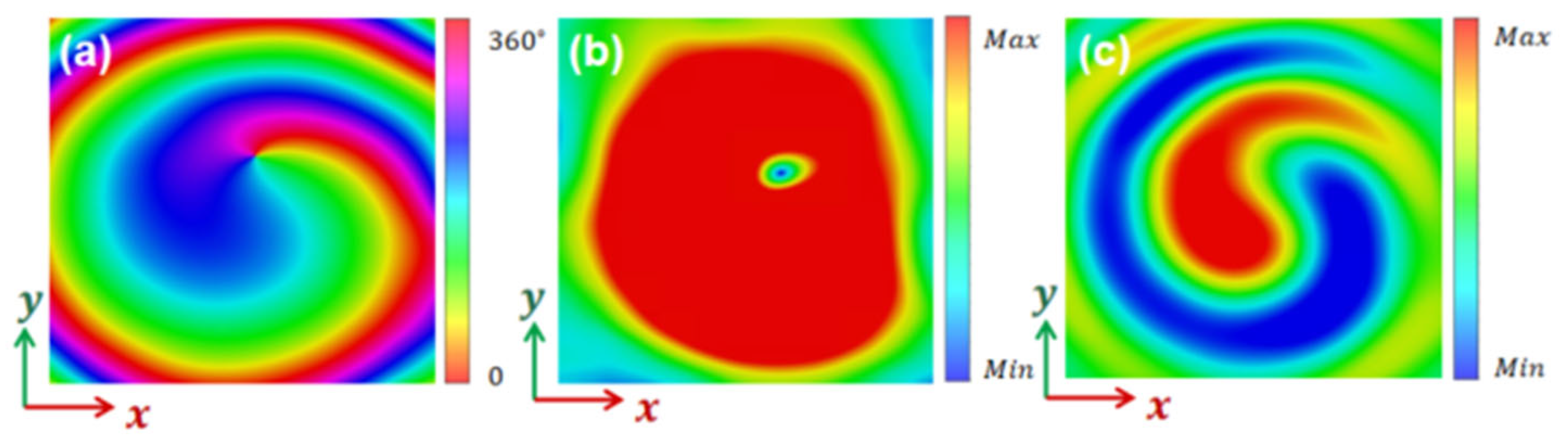
The simulation results of a transmissive superconfiguration material vortex phase plate of square lattice design under Gaussian beam excitation are obtained using a transient time-domain solver, and the phase, light intensity and field distributions of the topological charge l = 1 outgoing vortex beam in the xoy cross-section are shown in Figure 6. Figure 6a shows the phase distribution, and the results show that the phase of the outgoing light is spirally distributed and the phase change occurs along the counterclockwise direction. Figure 6b shows the light intensity distribution, which has a “donut” shape, with a phase singularity at the center point and zero intensity due to the uncertainty of the phase at the center point. Figure 6c shows the field distribution, which can be seen in the form of two spiral wings.
Figure 6.
Vortex beam with topological charge l = 1 for the vortex phase plate of a square lattice. (a) Cross-sectional phase distribution; (b) cross-sectional intensity distribution of light; (c) cross-sectional field distribution.
The top and side views of the transmissive metamaterial vortex phase plate designed using triangular lattice perforations, as shown in Figure 7a,b, with phase plate radius R = 15.3 and thickness 2.272 . The phase plate is simulated by using CST electromagnetic field simulation software, and the settings of excitation source, incident wavelength, and boundary conditions are unchanged. The refractive index on the phase plate is distributed from small to large in the counterclockwise direction, and the phase plate is placed at the beam waist of the Gaussian beam.
Figure 7.
Schematic diagrams of the vortex phase plate of a triangular lattice transmissive metamaterial. (a) Top view of the phase plate; (b) side view of the phase plate; (c) schematic diagram of the incident Gaussian beam on the phase plate.
Figure 8 shows the phase, intensity and field distribution of the outgoing vortex beam in the xoy cross-section for a topological charge l = 1. As can be seen from the figure, the phase of the outgoing light is spirally distributed, and the phase changes by 2 when rotating counterclockwise for one week; the light intensity is in the form of a “donut” ring, and the field distribution shows two spiral wing-like distributions rotating counterclockwise.
Figure 8.
Vortex beam with topological charge l = 1 for the vortex phase plate of a triangular lattice. (a) Cross-sectional phase distribution; (b) cross-sectional light intensity distribution; (c) cross-sectional field distribution.
Based on the above simulation results, it can be seen that both transmissive metamaterial vortex phase plates designed using a square lattice and a triangular lattice produce vortex beams with a topological charge number of one in the mid-infrared band.
4. Structural Design of Reflective Metamaterial Vortex Phase Plate
In the previous section, two types of transmissive metamaterial vortex phase plates were investigated to realize vortex beams. In this planar structure, the modulation of the incident electromagnetic wave phase depends on the spatial refractive index distribution on the phase plate, and the thickness of the phase plate is determined when the effective refractive index of each sector is determined. The thickness of the transmissive metamaterial vortex phase plate is h = 2.272 , the minimum hole diameter of the phase plate is 0.33 , and the ratio of the thickness to the smallest hole diameter is 6.88. The incident wavelength is 4.0 .
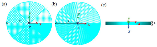
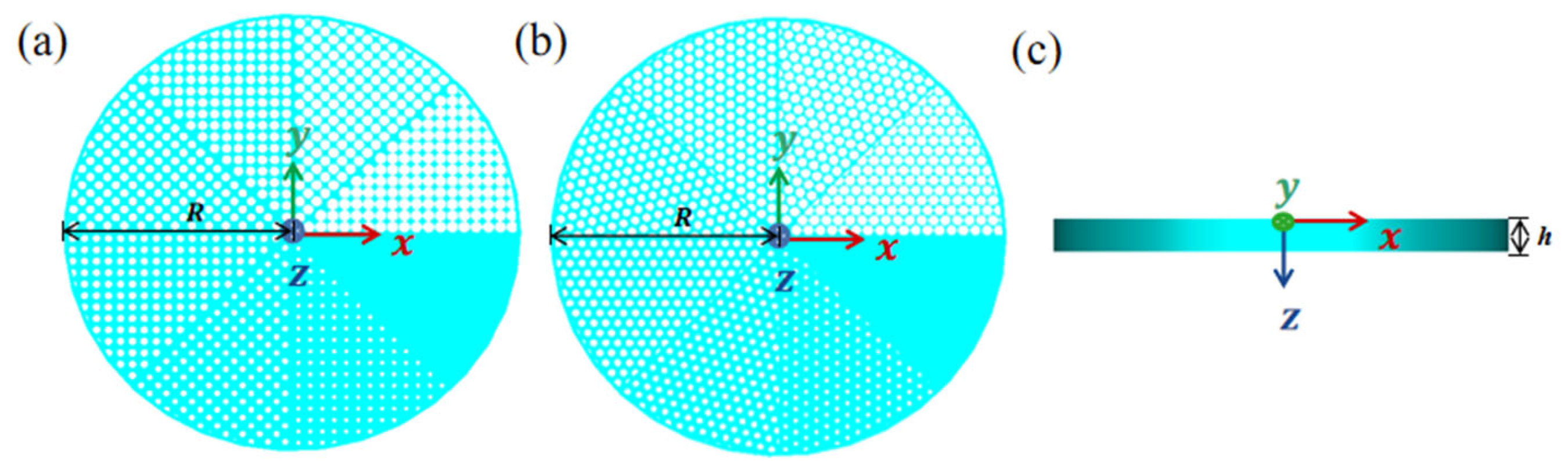
The reflective superstructure material vortex phase plate proposed in this section is nearly half the thickness of the transmissive phase plate and is attached to a metallic copper plate. When the incident light is obliquely incident on the phase plate, the electromagnetic wave will pass through the phase plate twice because of the high reflectivity of the copper metal substrate, thus ensuring the modulation of the electromagnetic wave phase by halving the thickness of the phase plate without changing the hole size, distribution and dielectric constant of the material on the phase plate. Based on the above analysis, two reflective metamaterial vortex phase plates are designed with thickness h = 1.136 and radius R = 15.3 . The structural diagrams of the two phase plates are shown in Figure 9. Figure 9a,b show the top view of the reflective metamaterial phase plate designed using a square lattice and a triangular lattice, respectively, and Figure 9c shows the side view of the two reflective phase plates. The ratio of the thickness of this phase plate to the minimum hole diameter is 3.44, which is thinner and lighter compared to the transmissive metamaterial vortex phase plate and easier to process.
Figure 9.
Schematic diagram of vortex phase plate of reflective superstructure material. (a) Top view of square lattice vortex phase plate; (b) top view of triangular lattice vortex phase plate; (c) side view of vortex phase plate.
5. Simulation Results of Reflective Metamaterial Vortex Phase Plate
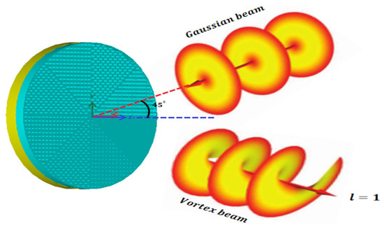
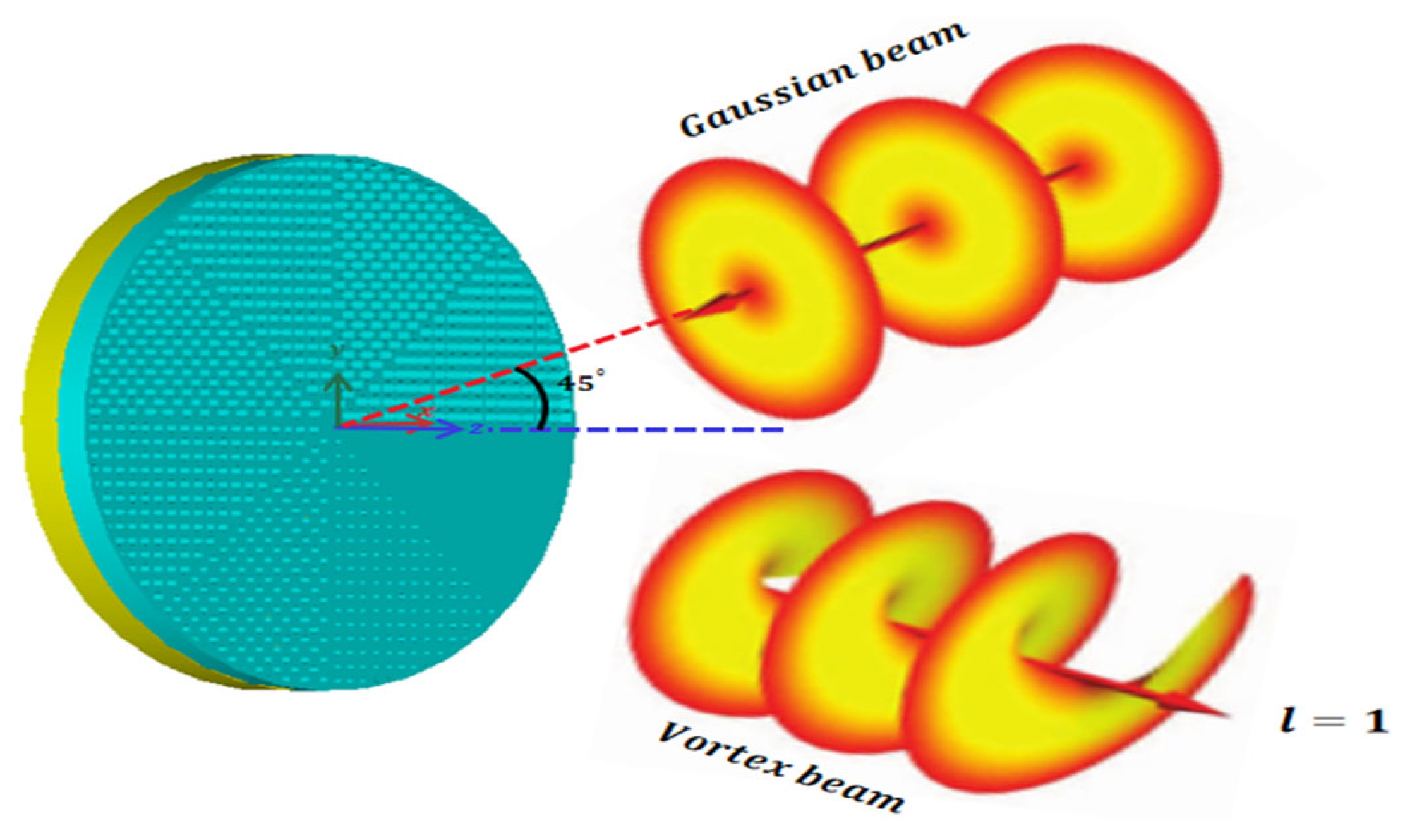
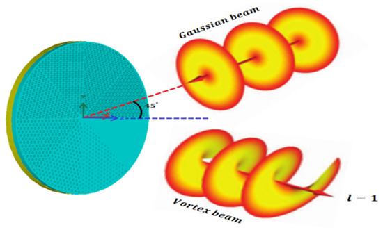
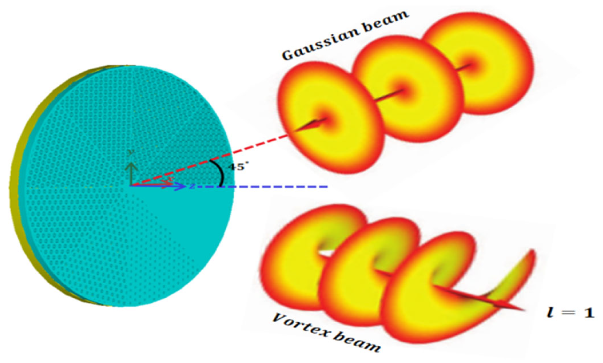
The CST electromagnetic simulation software is used to simulate the reflective metamaterial vortex phase plate with a square lattice design, as shown in Figure 10, the incident light is still a Gaussian beam, and the incident direction is . The incident light with the wavelength is at an angle of to the center axis of the phase plate with a distance of 30 m from the phase plate.
Figure 10.
Schematic diagram of a Gaussian beam incident on a square lattice reflective metamaterial vortex phase plate.
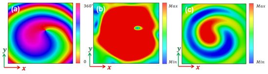
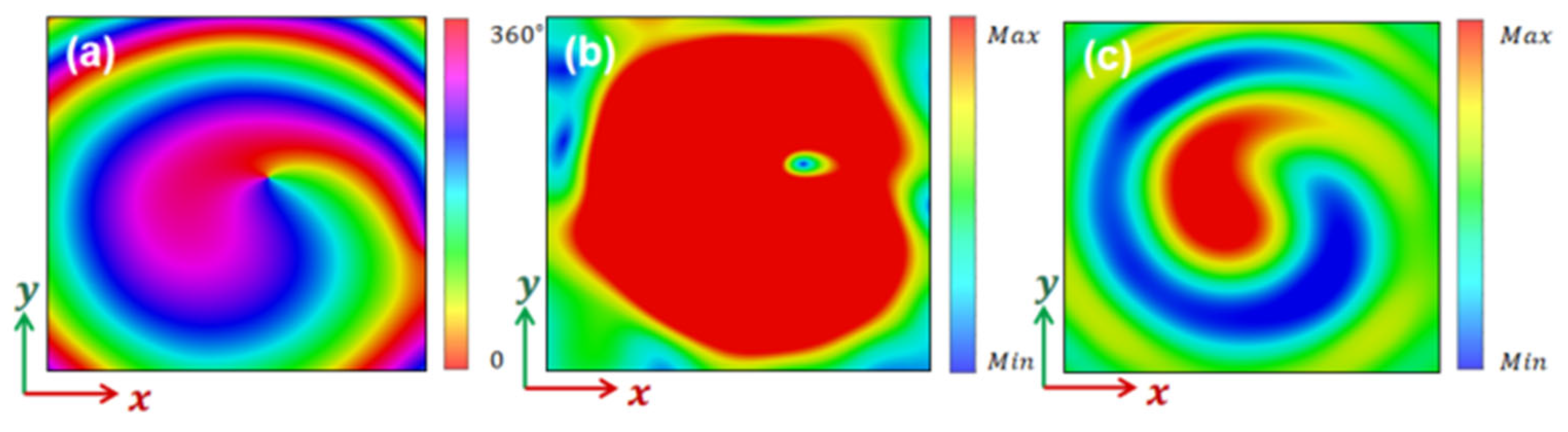
The simulation results of the reflective metamaterial vortex phase plate under Gaussian beam excitation are obtained by using the transient time domain solver, as shown in Figure 11. Figure 11a shows the phase distribution of the outgoing vortex light in the xoy cross-section when the Gaussian beam with the wavelength of is obliquely incident on the phase plate, and the results show that the phase of the outgoing light is spirally distributed and a phase change of occurs. The intensity distribution of the xoy cross-section of the outgoing vortex light is shown in Figure 11b, and the intensity distribution is similar to the “donut” type hollow circle distribution. Figure 11c shows the xoy cross-sectional electric field of the outgoing vortex light, and it can be seen that the reflective phase plate can produce almost the same field distribution as the transmissive one with two spiral wings rotating clockwise.
Figure 11.
Vortex beam with topological charge l = 1 for the square lattice reflective metamaterial vortex phase plate. (a) Cross-sectional phase distribution; (b) cross-sectional light intensity distribution; (c) cross-sectional field distribution.
The CST electromagnetic simulation software is used to simulate the reflective metamaterial vortex phase plate designed by the triangular lattice, and the conditions of excitation source, incident wavelength and boundary adjustment are set constant in the simulation. Figure 12 shows a schematic diagram of the reflective metamaterial vortex phase plate with a triangular lattice under Gaussian beam incidence conditions.
Figure 12.
Schematic diagram of a Gaussian beam incident on a triangular lattice reflective metamaterial vortex phase plate.
A reflective metamaterial vortex beam phase plate designed using a triangular lattice is simulated using a transient time-domain solver, and a vortex beam with topological charge l = 1 is obtained under Gaussian beam excitation when the refractive index on the phase plate is distributed from small to large in the counterclockwise direction. Figure 13 shows the phase, intensity and field distributions of the vortex beam with topological charge l = 1 in the xoy cross-section. From the phase distribution in Figure 13, it can be seen that the outgoing light phases are spirally distributed, and the phase changes by one week of rotation in the counterclockwise direction . It can also be seen from the figure that the light intensity distribution shows a “donut”-type ring distribution. The field distribution shows two counterclockwise rotating spiral wings. Therefore, our reflective metamaterial phase plate designed using a triangular lattice can successfully produce a vortex beam with topological charge l = 1.
Figure 13.
Vortex beam with topological charge l = 1 for the triangular lattice reflective metamaterial vortex phase plate. (a) Cross-sectional phase distribution; (b) cross-sectional light intensity distribution; (c) cross-sectional field distribution.
Based on the above simulation results, it can be seen that both of our designed reflective metamaterial vortex phase plates produce vortex beams with a topological charge number of one in the mid-infrared band. If there is preparation equipment and testing conditions, two types of vortex phase plates can be realized based on the above theory and design schemes.
6. Conclusions
In this paper, we proposed a new method to generate vortex beams based on planar metamaterials, which depend on an equivalent gradual refractive index of the subwavelength holes in the dielectric plate. Both transmissive and reflective vortex beam generators can generate vortex beams in the mid-infrared wavelength range, where the thickness of the reflective metamaterial generator is nearly half of the transmissive structure. By adjusting the size of the aperture on each sector, the refractive index on the phase plate is changed to achieve the regulation of the incident Gaussian beam intensity and phase. These new planar vortex beam generators have important application value to realize vortex beams in the mid-infrared band, and the design idea can be used to design high-performance vortex beam generators in visible, terahertz, and microwave bands.
Author Contributions
Conceptualization, J.S. and G.D.; Methodology, W.Q., X.G., Q.W., P.L., R.Y., J.L., J.S. and G.D.; Software(CST 2017), W.Q. and X.G.; Validation, W.Q., X.G., R.Y. and J.L.; Formal analysis, W.Q. and X.G.; Investigation, W.Q., X.G., R.Y. and J.L.; Resources, J.S. and G.D.; Writing—original draft, W.Q.; Writing—review & editing, J.S. and G.D.; Supervision, J.S. and G.D.; Project administration, G.D.; Funding acquisition, G.D. All authors have read and agreed to the published version of the manuscript.
Funding
This work is supported by the National Natural Science Foundation of China (Nos. 12275161 and 12235009) and the Key R&D Program of Shandong Province (2024KJHZ013). This work is supported by the Physical–Chemical Materials Analytical and Testing Center of Shandong University in Weihai.
Data Availability Statement
The data that support the findings of this study are available upon reasonable request from the authors.
Conflicts of Interest
The authors declare no conflicts of interest.
References
- Yao, A.M.; Padgett, M.J. Orbital Angular Momentum: Origins, Behavior and Applications. Adv. Opt. Photonics 2011, 3, 161–204. [Google Scholar] [CrossRef] [Scilit]
- Franke-Arnold, S.; Allen, L.; Padgett, M. Advances in Optical Angular Momentum. Laser Photonics Rev. 2008, 2, 299–313. [Google Scholar] [CrossRef] [Scilit]
- Jin, Y.; Wang, X.; Xia, Z.; Rao, X.; Chen, X.; Li, K.; Jiang, Y.; Chu, J.; Wu, D.; Qiu, C.-W.; et al. Multidimensional helical dichroism from a chiral molecular nanoassembly. Nat. Commun. 2026, 17, 1829. [Google Scholar] [CrossRef] [Scilit] [PubMed]
- Zhao, M.; Li, Y.; He, X.; Zhang, Y. Gallium Arsenide-Enabled Spatial Polarization-Frequency Multiplexing Metasurface for Terahertz Encrypted Communication. Mater. Sci. Semicond. Process. 2026, 201, 110042. [Google Scholar] [CrossRef] [Scilit]
- Li, H.; Zhao, C.; Xu, W.; Li, J.; Zheng, C.; Tan, Q.; Song, C.; Xu, H.; Shen, Y.; Yao, J.-Q. Twisted bilayer meta-device for on-demand terahertz polarization filtering. Photon. Res. 2025, 13, 1116–1129. [Google Scholar] [CrossRef] [Scilit]
- Yu, L.; Pietila, J.; Singh, H.J.; Caglayan, H. Phase-Shifting Structured Illumination with a Polarization-Encoded Metasurface. Nano Lett. 2025, 25, 11696–11702. [Google Scholar] [CrossRef] [Scilit]
- Anzolin, G.; Tamburini, F.; Bianchini, A.; Umbriaco, G.; Barbieri, C. Optical Vortices with Starlight. Astron. Astrophys. 2008, 488, 1159–1165. [Google Scholar] [CrossRef] [Scilit]
- Swartzlander, G.A.; Ford, E.L.; Abdul-Malik, R.S.; Close, L.M.; Peters, M.A.; Palacios, D.M.; Wilson, D.W. Astronomical Demonstration of an Optical Vortex Coronagraph. Opt. Express 2008, 16, 10200–10207. [Google Scholar] [CrossRef] [Scilit]
- Cozzolino, D.; Polino, E.; Valeri, M.; Carvacho, G.; Bacco, D.; Spagnolo, N.; Oxenløwe, L.K.; Sciarrino, F. Air-Core Fiber Distribution of Hybrid Vector Vortex-Polarization Entangled States. Adv. Photonics 2019, 1, 046005. [Google Scholar] [CrossRef] [Scilit]
- Cardano, F.; D’errico, A.; Dauphin, A.; Maffei, M.; Piccirillo, B.; de Lisio, C.; De Filippis, G.; Cataudella, V.; Santamato, E.; Marrucci, L.; et al. Detection of Zak Phases and Topological Invariants in a Chiral Quantum Walk of Twisted Photons. Nat. Commun. 2017, 8, 15516. [Google Scholar] [CrossRef] [Scilit]
- Wu, Z.; Zhao, J.; Dou, J.; Liu, J.; Jing, Q.; Li, B.; Hu, Y. Optical Trapping of Multiple Particles Based on a Rotationally-Symmetric Power-Exponent-Phase Vortex Beam. Opt. Express 2022, 30, 42892–42901. [Google Scholar] [CrossRef] [Scilit] [PubMed]
- Chen, M.; Huang, S.; Liu, X.; Chen, Y.; Shao, W. Optical Trapping and Rotating of Micro-Particles using the Circular Airy Vortex Beams. Appl. Phys. B 2019, 125, 184. [Google Scholar] [CrossRef] [Scilit]
- Wan, Z.; Shen, Y.; Wang, Z.; Shi, Z.; Liu, Q.; Fu, X. Divergence-Degenerate Spatial Multiplexing towards Future Ultrahigh Capacity, Low Error-Rate Optical Communications. Light Sci. Appl. 2022, 11, 144. [Google Scholar] [CrossRef] [Scilit] [PubMed]
- Ali, A.; Khalily, M.; Brown, T.; Tafazolli, R. Metasurface-Based Thz Reflectarray Antenna with Vortex Multiplexing and Beam-Steering Capabilities for Future Wireless Communications. iScience 2022, 25, 104725. [Google Scholar] [CrossRef] [Scilit]
- Hnatovsky, C.; Shvedov, V.G.; Krolikowski, W.; Rode, A.V. Materials Processing with a Tightly Focused Femtosecond Laser Vortex Pulse. Opt. Lett. 2010, 35, 3417–3419. [Google Scholar] [CrossRef] [Scilit]
- Jin, Y.; Allegre, O.J.; Perrie, W.; Abrams, K.; Ouyang, J.; Fearon, E.; Edwardson, S.P.; Dearden, G. Dynamic Modulation of Spatially Structured Polarization Fields for Real-Time Control of Ultrafast Laser-Material Interactions. Opt. Express 2013, 21, 25333–25343. [Google Scholar] [CrossRef] [Scilit]
- Nivas, J.J.J.; Shutong, H.; Anoop, K.K.; Rubano, A.; Fittipaldi, R.; Vecchione, A.; Paparo, D.; Marrucci, L.; Bruzzese, R.; Amoruso, S. Laser Ablation of Silicon Induced by a Femtosecond Optical Vortex Beam. Opt. Lett. 2015, 40, 4611–4614. [Google Scholar] [CrossRef] [Scilit]
- Wang, J.; Yang, J.Y.; Fazal, I.M.; Ahmed, N.; Yan, Y.; Huang, H.; Ren, Y.; Yue, Y.; Dolinar, S.; Tur, M.; et al. Terabit Free-Space Data Transmission Employing Orbital Angular Momentum Multiplexing. Nat. Photonics 2012, 6, 488–496. [Google Scholar] [CrossRef] [Scilit]
- Zhou, Q.; Liu, M.; Zhu, W.; Chen, L.; Ren, Y.; Lezec, H.J.; Lu, Y.; Agrawal, A.; Xu, T. Generation of Perfect Vortex Beams by Dielectric Geometric Metasurface for Visible Light. Laser Photonics Rev. 2021, 15, 2100390. [Google Scholar] [CrossRef] [Scilit]
- Liu, Y.; Chen, W.; Zhang, W.; Ma, C.Q.; Chen, H.X.; Xiong, Y.F.; Yuan, R.; Tang, J.; Chen, P.; Hu, W.; et al. Visible and Online Detection of Near-Infrared Optical Vortices via Nonlinear Photonic Crystals. Adv. Opt. Mater. 2022, 10, 2101098. [Google Scholar] [CrossRef] [Scilit]
- Zhang, X.; Kong, D.; Liu, S.-J.; Wang, H. All-Dielectric Metasurface with Multi-Function in the Near-Infrared Band. J. Opt. Soc. Am. A 2020, 37, 1731–1739. [Google Scholar] [CrossRef] [Scilit] [PubMed]
- Sawant, A.; Lee, I.; Choi, E. Amplitude Non-Uniformity of Millimeter-Wave Vortex Beams Generated by Transmissive Structures. IEEE Trans. Antennas Propag. 2022, 70, 4623–4631. [Google Scholar] [CrossRef] [Scilit]
- Ni, J.; Wang, C.; Zhang, C.; Hu, Y.; Yang, L.; Lao, Z.; Xu, B.; Li, J.; Wu, D.; Chu, J. Three-Dimensional Chiral Microstructures Fabricated by Structured Optical Vortices in Isotropic Material. Light Sci. Appl. 2017, 6, e17011. [Google Scholar] [CrossRef] [Scilit] [PubMed]
- Boichenko, S. Toward Super-Resolution Fluorescent Microscopy of Arbitrarily Oriented Single Molecules. Phys. Rev. A 2020, 101, 043823. [Google Scholar] [CrossRef] [Scilit]
- Wang, J. Advances in Communications using Optical Vortices. Photonics Res. 2016, 4, B14–B28. [Google Scholar] [CrossRef] [Scilit]
- Aadhi, A.; Sharma, V.; Singh, R.P.; Samanta, G.K. Continuous-Wave, Singly Resonant Parametric Oscillator-Based Mid-Infrared. Opt. Lett. 2017, 42, 3674–3677. [Google Scholar] [CrossRef] [Scilit]
- Dharmavarapu, R.; Izumi, K.; Katayama, I.; Ng, S.H.; Vongsvivut, J.; Tobin, M.J.; Kuchmizhak, A.; Nishijima, Y.; Bhattacharya, S.; Juodkazis, S. Dielectric Cross-Shaped-Resonator-Based Metasurface for Vortex Beam Generation at Mid-Ir and Thz Wavelengths. Nanophotonics 2019, 8, 1263–1270. [Google Scholar] [CrossRef] [Scilit]
- Lu, G.; Wu, F.; Zheng, M.; Chen, C.; Zhou, X.; Diao, C.; Liu, F.; Du, G.; Xue, C.; Jiang, H.; et al. Perfect Optical Absorbers in a Wide Range of Incidence by Photonic Heterostructures Containing Layered Hyperbolic Metamaterials. Opt. Express 2019, 27, 5326–5336. [Google Scholar] [CrossRef] [Scilit]
- Ma, J.S.; Fan, L.N. Design of Resonant Waveguide Grating Filter with Reflection and Transmission Modes. Chin. Opt. 2020, 13, 1147–1157. [Google Scholar] [CrossRef] [Scilit]
- Yang, Z.; Zhu, D.; Lu, D.; Zhao, M.; Ning, N.; Liu, Y. Study of the relationship between porosity and refractive index in nanoporous thin films. J. Opt. 2003, 23, 1366–1369. [Google Scholar]
- Hayat, T.; Afzal, M.U.; Lalbakhsh, A.; Esselle, K.P. Additively Manufactured Perforated Superstrate to Improve Directive Radiation Characteristics of Electromagnetic Source. IEEE Access 2019, 7, 153445–153452. [Google Scholar] [CrossRef] [Scilit]
- Shao, W.; Chen, Q. Single-Pixel Scanning Near-Field Imaging with Subwavelength Resolution using Sharp Focusing Mikaelian Lens. IEEE Trans. Microw. Theory Tech. 2022, 71, 795–804. [Google Scholar] [CrossRef] [Scilit]
- Petosa, A.; Ittipiboon, A. Design and Performance of a Perforated Dielectric Fresnel Lens. IEE Proc. Microw. Antennas Propag. 2003, 150, 309–314. [Google Scholar] [CrossRef] [Scilit]
- Viallon, M.; Assaf, S.; Treizebre, A.; Gidik, H.; Dupont, D.; Bedek, G.; Caillibotte, M.; Djafari-Rouhani, B.; Thomy, V.; Pennec, Y.; et al. Modulation of the Refractive Properties of 1D and 2D Photonic Crystal Polycrystalline Silicone-Based Membranes in the Mir Frequency Range. J. Phys. D Appl. Phys. 2019, 52, 205101. [Google Scholar] [CrossRef] [Scilit]






Disclaimer/Publisher’s Note: The statements, opinions and data contained in all publications are solely those of the individual author(s) and contributor(s) and not of MDPI and/or the editor(s). MDPI and/or the editor(s) disclaim responsibility for any injury to people or property resulting from any ideas, methods, instructions or products referred to in the content. |
© 2026 by the authors. Licensee MDPI, Basel, Switzerland. This article is an open access article distributed under the terms and conditions of the Creative Commons Attribution (CC BY) license.