Abstract
For high-speed compound helicopters, such as the S-97 Raider, the reflection and diffraction effects of vertical/horizontal tails on pusher propeller noise are inevitable. To investigate the noise distortion effect of the rear-mounted pusher propeller, this study first relies on the Chinese Laboratory of Rotorcraft Navier-Stokes (CLORNS) solver, adopting the high-resolution Perturbed polynomial reconstructed Targeted Essentially Non-Oscillatory scheme (TENO-P) combined with the Delayed Detached Eddy Simulation based on the Spalart–Allmaras (SA-DDES) turbulence model to resolve the multi-scale rotor flowfield. Additionally, a continuous and conserved acoustic source extraction method is proposed to eliminate non-physical waves at the one-way Computational Fluid Dynamics and Computational AeroAcoustics (CFD–CAA) coupling interface, addressing the temporal inconsistency between flowfield evolution and acoustic propagation. Finally, numerical investigations are conducted on the instantaneous acoustic wave propagation and acoustic directivity of the pusher propeller under the influence of vertical/horizontal tails. The results show that significant acoustic distortion occurs when pusher propeller-generated noise interacts with vertical/horizontal tails. This interaction not only produces reflected and diffracted acoustic waves but also leads to wavefront discontinuities, the formation of short acoustic waves, and changes in acoustic directivity. The maximum variation in the sound pressure level reaches 10 dB at local azimuths. The distortion effect of tails on pusher propeller noise is closely correlated with the number of propeller blades. The interaction process between the propeller and tails becomes more complex with the increase in blade count, resulting in the generation of shorter acoustic waves. For the six-blade rotor, the originally continuous acoustic wave branch can be split into up to four short waves. This study confirms that the proposed Hybrid Computational AeroAcoustics (HCAA) method holds significant application prospects in the aeroacoustic research of compound helicopters.
1. Introduction
To address the forward-speed limitations of conventional single-main-rotor helicopters, Sikorsky pioneered the compound helicopter configuration integrated with the Advancing Blade Concept (ABC) rotor system, represented by the X-2 Technology Demonstrator (X2TD), 4-ton S-97 Raider, and 13-ton SB > 1 Defiant (Figure 1) [1]. These high-speed platforms rely on rear-mounted pusher propellers for thrust augmentation and vertical/horizontal tails for stability control, making the propeller-tail assembly a core aerodynamic and aeroacoustics component [2,3]. Standard MIL-STD-1474D (1977) [4] has imposed restrictions on helicopter noise exposure, mandating that the maximum steady-state noise for an 8-h daily exposure duration be less than 85 dB(A). However, various helicopters, such as the UH-1H, AH-1G, and CH-47C, have not met this standard. As aviation noise regulations become more and more stringent, noise annoyance has emerged as a critical barrier to the deployment of compound helicopters in tactical missions. Unlike conventional helicopters, the high-speed rotating pusher propeller of compound configurations generates intense acoustic waves that interact with the adjacent vertical/horizontal tails, inducing multiple reflections and diffractions that distort noise propagation, thus forming the “installation effect.” Despite its role in undermining noise control efforts and introducing uncertainties in acoustic prediction, this “installation effect” has long been overlooked in research due to technical constraints. Yet with the tightening of aviation noise regulations, this issue can no longer be ignored, especially as it directly impacts the successful deployment of compound helicopters in key application scenarios like tactical operations.
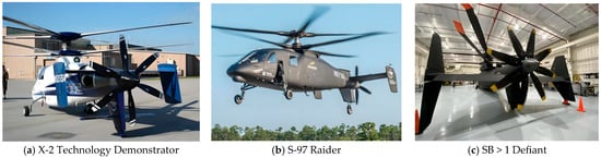
Figure 1.
The compound high-speed helicopter with a pusher propeller.
Existing research on compound helicopter aeroacoustics has laid a solid foundation for understanding key noise sources, with a primary focus on coaxial rotors. For instance, Qi et al. [5] developed a high-efficiency trim model that successfully elucidated the aerodynamic interaction mechanism of coaxial rotors in hover, providing critical insights into rotor wake evolution. Yuan et al. [6] further advanced this field by analyzing unsteady aerodynamic fluctuations of coaxial rotors in low-speed forward flight, which significantly improved the accuracy of rotor noise source identification. Jia et al. [7,8] innovatively coupled Computational Fluid Dynamics and Computational Structural Dynamics (CFD/CSD) to investigate the aerodynamic–acoustic characteristics of lift-offset coaxial rotors, while Zhong et al. [9] proposed a practical prediction model for counter-rotating coaxial rotor noise based on the blade element theory, with both studies offering valuable tools for coaxial rotor noise evaluation. While these works have significantly advanced our understanding of lift-system noise, they have predominantly focused on the main rotor assembly, devoting relatively less attention to the acoustics of the pusher propellers.
In the broader field of propeller noise research, scholars have made notable progress in noise reduction and prediction, though the application scenarios remain limited. Yuan et al. [3] optimized the aerodynamic performance of pusher propellers for compound helicopters across optimal and high-speed ranges, laying the groundwork for the design of efficient pusher systems. Yu et al. [10] achieved a 5 dB reduction in the overall sound pressure level (OASPL) of a 6-blade propeller without sacrificing thrust, offering a feasible path for low-noise propeller optimization. Pagano et al. [11] similarly reduced the OASPL of a wing-mounted pusher propeller by 3.5 dB during takeoff, providing targeted solutions for aircraft takeoff noise control. Chiaramonte et al. [12] explored propeller–wing aerodynamic interactions, revealing how blade tip vortex trajectories alter wing lift/drag distributions—findings that support the integrated design of propeller–airframe systems. Yin et al. [13] further coupled CFD with the Ffowcs–Williams–Hawkings (FW-H) equation to analyze wing-mounted propeller aeroacoustics, establishing a mature framework for far-field noise prediction in simple configurations. These studies primarily focus on isolated propellers or propeller–wing combinations and have not yet incorporated the vertical/horizontal tails into the acoustic analysis. Regarding the noise characteristics of compound helicopter pusher propellers, Soderman et al. [14] performed comprehensive experimental investigations into the impacts of Y-Tail, V-Tail, and I-Tail configurations on pusher propeller noise. Sun et al. [15] investigated the noise of pusher propellers by integrating computational fluid dynamics (CFD) with the FW-Hpds equation. However, as for the FW-H equation, though efficient for free-field propagation, it has inherent limitations in capturing the multiple reflections and diffraction effects of complex tail geometries, which are essential for compound helicopter configurations.
The core challenge in addressing propeller–tail noise interaction lies in bridging the gap between existing methods and the complex acoustic propagation scenarios of compound helicopters. The investigations of propeller noise mentioned above primarily rely on the theoretical method or the FW-H equation, and the installation effect of the wings on the pusher propeller noise is only considered during the simulation of the unsteady flowfield. For the compound high-speed helicopter with the same configuration as the X2TD, the propagation of the rear-mounted pusher propeller noise is affected by the multiple-reflection effect and the diffraction effect of the vertical/horizontal tails. As highlighted by Redonnet et al. [16,17,18], such a challenging acoustic propagation issue could only be well solved with the use of a Computational AeroAcoustics (CAA) solver, such as the sAbrinA [19], which enables the simultaneous consideration of both the effects of the non-uniform flowfield and the fuselage.
To address this research gap while building on the strengths of existing work, our team previously developed a HCAA solver [20,21], which is capable of predicting rotor noise propagation in non-uniform flowfields and strong shear layers. Building on this foundation, the present work advances both CFD and CAA solvers to specifically address the tail–pusher propeller noise interaction: (1) the CLORNS solver is enhanced with the high-resolution TENO-P scheme [22] proposed by our research group and the SA-DDES turbulence model, enabling the more accurate capture of multi-scale rotor flowfields and unsteady aerodynamic fluctuations, thereby complementing the aerodynamic analysis of existing propeller studies; (2) a continuous and conserved acoustic source extraction method is proposed to eliminate non-physical waves on the CFD–CAA interface, resolving the temporal inconsistency between flowfield evolution and acoustic propagation, which addresses the interface constraint of conventional coupling methods; (3) wall boundary conditions for Linearized Euler Equations (LEEs) are integrated into the HCAA solver to explicitly model the reflection/diffraction effects of vertical/horizontal tails, thus extending the applicability of CAA methods to complex tail geometries. This study aims to conduct the first numerical investigation of pusher propeller noise distortion induced by vertical/horizontal tails. By analyzing instantaneous acoustic waves and acoustic directivity under different blade counts, we seek to reveal the noise distortion mechanism and validate the HCAA method as a reliable tool for compound helicopters, thereby supplementing the existing research framework on propeller–airframe acoustic interactions.
2. Flowfield and Aeroacoustic Simulation Methods
To develop a sophisticated HCAA solver that accounts for the reflection and diffraction effects of intricate geometries, two core components are essential: (1) a high-fidelity CFD solver equipped with high-resolution spatial discretization schemes and advanced turbulence models, which enables it to capture multi-scale vortex structures and unsteady aerodynamic fluctuations, thereby acting as the acoustic source for the CAA solver; (2) a comprehensive CAA solver designed to simulate sound wave propagation in the presence of complex geometries and non-uniform flowfields.
2.1. Flowfield Simulation Method
An improved flowfield solver, termed CLORNS [23,24,25], was developed to simulate the unsteady rotor flowfield. This solver adopts a moving embedded grid, with the Navier–Stokes equations employed as the governing equations, which can be expressed in the following form:
where U represents the conserved variables, while and represent the convective flux and the viscous flux, respectively.
To enhance the resolution of multi-scale vortex structures in the rotor flowfield and improve the prediction accuracy of unsteady aerodynamic forces, the Delayed Detached Eddy Simulation (DDES) model [26,27] is developed based on the one-equation Spalart-Allmaras (SA) turbulence model [28]. The SA-DDES model employs the Reynolds–Averaged Navier–Stokes (RANS) equations coupled with the SA turbulence model to resolve the unsteady flowfield near the wall of the rotor blade, while adopting the Large Eddy Simulation (LES) approach to capture the unsteady multi-scale rotor wake flowfield [29]. Compared with the standard SA turbulence model, the normal distance is replaced by a distance function as follows:
The CDES parameter serves as a key constant bridging the wall distance parameter and grid scale characteristics. Calibrated through numerous three-dimensional benchmark cases, its optimal value was ultimately determined to be 0.65, and this value is employed is the present work. The DDES model necessitates that the spatial discretization method is of a high order of accuracy and high resolution for resolving the multi-scale vortex structures of the rotor flowfield. For this purpose, the novel TENO-P scheme proposed by our research group is used to reconstruct the variables on the left and right sides of the cell. The TENO-P scheme is proposed, built on the foundation of the fifth-order TENO scheme, using the idea of perturbed polynomial reconstruction. The TENO-P scheme maintains the low-dissipation advantages of the standard TENO5 scheme with one-order accuracy improvement achieved [22].
Figure 2 depicts the embedded grid used for simulating the multi-scale rotor flowfield. The embedded grid consists of two parts: the body-fitted blade grid and the background grid. The background grid is refined to meet the grid-resolution criteria of the LES method in the rotor wake region, while the blade grid is generated by interpolating and folding the two-dimensional airfoil grid to satisfy the resolution requirements of the unsteady RANS method. The surfaces of the blade grids are set as no-slip wall boundary conditions, while the outer boundaries of the background grids are specified as far-field non-reflecting boundary conditions based on the Riemann invariants.
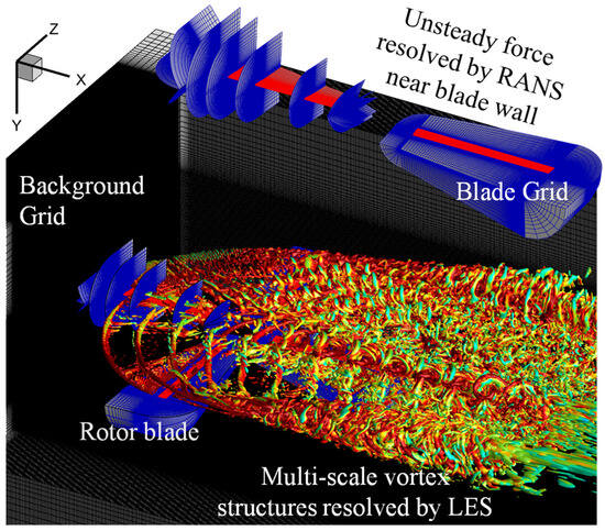
Figure 2.
Embedded grid for simulating the multi-scale rotor flowfield.
2.2. Aeroacoustic Prediction Method
An improved acoustic propagation solver was developed to predict the scattering field of pusher propeller noise induced by the vertical/horizontal tails. The Linearized Euler Equations were adopted as the governing equations for the HCAA solver [20,21]. The HCAA solver is developed using an unstructured grid composed of tetrahedral elements. The high-order Runge–Kutta Discontinuous Galerkin (RKDG) method is used for temporal and spatial discretization. The characteristic-based inflow boundary is utilized on the one-way CFD–CAA coupling surface, and the characteristic-based non-reflective boundary condition is employed on the far-field boundary to avoid non-physical reflected waves. The computational accuracy and stability of the HCAA solver have been well verified using the theoretical data on the benchmark problem and the experimental data on the rotor noise in [20,21]. The three-dimensional Linearized Euler Equations in differential form can be written as follows:
where , , and are the flux vectors, and vector contains terms related to the gradient of the non-uniform flowfield.
where and are, respectively, the density and pressure of acoustic waves. , , and are the particle velocity. , , , , and are the corresponding mean quantities. is the ratio of specific heats of the air.
Figure 3 shows the 3D unstructured grid for the study in the present work. Panels (a) and (b) depict the unsteady vortex of the propeller and the distorted acoustic wave of the propeller under the effect of the vertical/horizontal tails. Panels (c)–(e) show the schematics of the grid partition in the three directions. The grid distributed on the fuselage is refined to account for the scattering effect of the wall, and the grid in the zone near the wall is refined to resolve the propagation and mutual interaction of the acoustic waves.
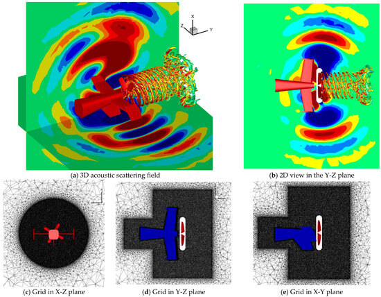
Figure 3.
The unstructured grid for simulating acoustic scattering.
The one-way CFD–CAA coupling surface is used for the transmission of acoustic information from the CFD zone to the CAA zone. For a stationary medium, the acoustic source extraction method, building on the pressure, pressure gradient, and equation of state, is as follows:
where is the speed of sound. The notation “−” above a variable denotes its corresponding unsteady aerodynamic component. To ensure the continuity and conservation of acoustic source signals on the one-way CFD–CAA coupling surface, a novel acoustic source extraction method was proposed. Once the pressure and pressure gradients on the coupling surface are obtained from the CFD results, these four variables (being time-dependent only) can be expanded in the form of a Fourier series. Since time-averaged components do not belong to the acoustic source, they are subtracted, leading to the modified form of Equation (7) as follows:
where represents the number of the Fourier series terms, and is used in this work. represents the number of source sampling points within one rotor noise period. represents one period of the rotor noise, that is, the blade passing frequency (BPF). , , , , , , , and are the coefficients of the Fourier series to be determined using the CFD results. By solving the above equations, the continuous and conserved acoustic source information on the CFD–CAA one-way coupling surface can be obtained as follows:
For the moving medium, the continuous and conserved acoustic source extraction method, building on the unsteady aerodynamic fluctuation, is as follows:
where the notation “−” above a variable denotes its corresponding unsteady aerodynamic component. The definitions of , , , and are the same as those in Equation (8), while , , , , , and are the coefficients of the Fourier series to be determined using the unsteady velocity fluctuation.
The characteristic outflow boundary condition is utilized on the far-field to avoid the non-physical reflection of acoustic waves. For the wall boundary, a reflected wall boundary condition was adopted to account for the effects of vertical/horizontal tails, with its mathematical expression given as:
Among them, , , and represent the normal vectors of the wall, respectively. Both the fluid and the acoustic fields must satisfy the non-penetrating boundary condition at the wall. Therefore, the normal components of both the fluid velocity and particle velocity at the wall boundary are equal to zero.
2.3. Validation of the Flowfield Solver
Experimental data on the HART-II baseline configuration, featuring a strong Blade Vortex Interaction (BVI) during descent flight, were used to validate the unsteady flowfield solver [30,31,32]. The validation was conducted using a modified BO-105 model rotor, which has four blades with a modified NACA23012 airfoil. The radius of the model rotor is m with a chord length of 0.061 m, given an aspect ratio of 16.5289. The rotor blades are rectangular with an 8° linear twist from root to tip. The effective rotor shaft angle is 4.5°. The rotor is operated at a rotational speed of rad/s and a free-stream velocity of m/s, giving an advance ratio of , which is defined as:
The motion of the rotor blade within one rotor period is as follows [32]:
where represents the rotor azimuth angle, and represents the collective pitch angle.
Three meshes with varying resolutions, denoted as coarse, medium, and fine, are employed to investigate grid convergence. The resolution of the body-fitted blade grid is the same across the three meshes, all set to . In contrast, the resolutions of the background grids for these three meshes are , , and , respectively. The grid spacings in the refined zone of the three background grids are , , and (where is the chord length of rotor blade), respectively. Figure 4a–c compares the pressure distributions at three spanwise locations (0.75R, 0.87R, 0.97R) when the blade is at 120° azimuth. Figure 4d presents the CnM2 time history (where Cn denotes the section normal force coefficient and M represents the total local Mach number) at the 0.87R spanwise section. Both the predicted pressure distributions and air loads are in good agreement with the experimental data, and a clear grid convergence trend is observed as the mesh resolution increases. The results from the medium and fine meshes overlap closely, and both align more closely with the experimental data than those from the coarse mesh. Besides, the unsteady air-load fluctuations caused by the blade–vortex interaction between the 270° and 330° azimuth are well resolved. It is worth pointing out that since hub interference is not incorporated into the CFD simulation, notable discrepancies in unsteady air loads at 0° azimuth exist between the computed results and the experimental data. Figure 5 shows the multi-scale vortex structures generated by rotor blade motion for the three meshes (with Q = 0.002). The iso-surfaces of the Q-criterion are colored by the vorticity magnitude with 21 equal-spaced levels from 0 to 0.2. The resolution of multi-scale vortices improves with background grid refinement. Compared with the coarse mesh, the medium mesh effectively resolves interactions between the blade, tip vortex, root vortex, secondary vortex, and worm vortex. The fine mesh further reduces dissipation, enabling the capture of more intricate vortex structures.
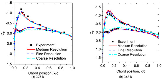
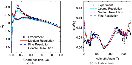
Figure 4.
Comparison of the pressure distribution at a 120° azimuth angle.
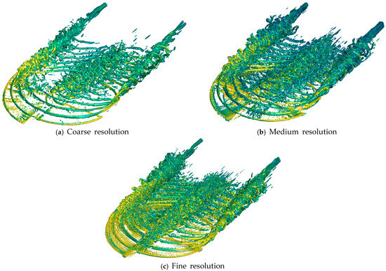
Figure 5.
Multi-scale vortex structures resolved using different meshes (Q = 0.002).
2.4. Validation of the Acoustic Solver
Experimental acoustic data on the SR2 propeller [33] are utilized for aeroacoustic validation. The SR2 propeller consists of straight blades, featuring the NACA 65 airfoil section from the root to 37% of its spanwise extension, and the NACA 16 airfoil section from 44% to the blade tip. A linear transition is implemented in the mid-region, from 37% to the 44% spanwise position, seamlessly connecting the NACA 65 airfoil to the NACA 16 airfoil. The geometrical details of the SR2, which include the blade-width ratio, design angle, blade-thickness ratio, and its three-dimensional model, are given in Figure 6.
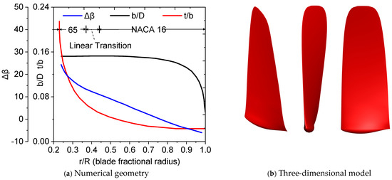
Figure 6.
Geometry of the SR2 propeller.
The SR2 propeller consists of eight blades with a diameter of 0.622 m, giving an aspect ratio of 3.27. The propeller rotates at 6487 RPM (revolutions per minute) with a 59-degree angle at the 0.75 spanwise position. The free-stream Mach number is 0.6, giving an advance ratio of , which is defined as:
where represents the free-stream velocity in , represents the rotational speed in RPS (revolutions per second), and represents the diameter. Twelve microphones are placed along the line parallel to the propeller rotation axis with a distance of 0.3 diameters away from the propeller tip. Figure 7 presents the schematic of the microphone positions. The locations of the twelve microphones are given as a function of the YM coordinate in and the angle from upstream in Table 1.
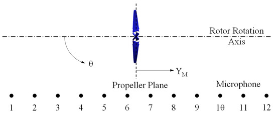
Figure 7.
Schematic of the microphone positions.

Table 1.
Locations of the twelve microphones.
For the unsteady flowfield simulation of the eight-blade SR2 propeller, the resolution of the blade grid is . The resolution of the background grid is , and the grid spacing is in the three directions. Figure 8 shows the mesh for simulating the aeroacoustic propagation; the whole computational domain is decomposed into two zones. The finest grid is used in Zone 1 to resolve the acoustic waves around the pusher propeller, while the grid in Zone 2 is coarsened to damp the non-physical acoustic waves on the far-field boundary. Three meshes with different resolutions are used to investigate the acoustic propagation of the eight-blade SR2 propeller. The computational domain size remains consistent for the three meshes, with varying grid spacings in Zone 1 and Zone 2. Detailed parameters regarding the computational domain size and grid spacing are listed in Table 2.
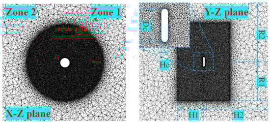
Figure 8.
Partition strategy for the CAA mesh.
Table 2.
Domain size and grid spacing for the three CAA meshes.
Figure 9 illustrates the tone directivities at the first BPF (blade passing frequency) of the eight-blade SR2 propeller from the three meshes with different resolutions, with results from Tan et al. [34] included for comparison. The HCAA method exhibits an excellent performance in predicting the sound pressure level (SPL, in dB), with the results in good agreement with the experimental data. Compared with the predictions obtained from the FW-Hpds equations, the HCAA results align more closely with the experimental measurements, thus verifying the method’s reliability. As further evidence, Figure 9b presents the distribution and comparison of prediction errors across different methods; notably, the calculation error analysis reveals that the linearized Euler equations yield significantly lower prediction errors than the FW-Hpds method. Specifically, for azimuthal angles spanning from 70° to 110°, the numerical error associated with the LEE method remains below 1 dB, while the lowest error obtained using the FW-Hpds based methodology reported by Tan et al. surpasses 4 dB.

Figure 9.
Tone directivities and instantaneous acoustic waves of the SR2 propeller.
Figure 9.
Tone directivities and instantaneous acoustic waves of the SR2 propeller.

3. Analyses of the Results
3.1. Simulation Model and Acoustic Probe Array
Figure 10a presents the geometric configuration of the pusher propeller and the vertical/horizontal tails adopted in this study. To ensure the relevance and engineering applicability of the research to typical high-speed compound helicopter platforms, the vertical/horizontal tails are designed with reference to the structural characteristics of the Sikorsky S-97 Raider, specifically featuring a “H” shape, and a downward-extending central vertical tail that serves as the mounting structure for the helicopter’s rear wheel, consistent with the practical layout of the S-97 Raider. For investigating the influence of the propeller blade count on the acoustic installation effect, two pusher propeller models with different blade numbers (four-blade and six-blade) are selected as research objects. To maintain consistency with the aeroacoustic validation experiment and ensure the reliability of the simulation results, the geometric parameters of the propeller blades are identical to those of the SR2 propeller used in the validation test.
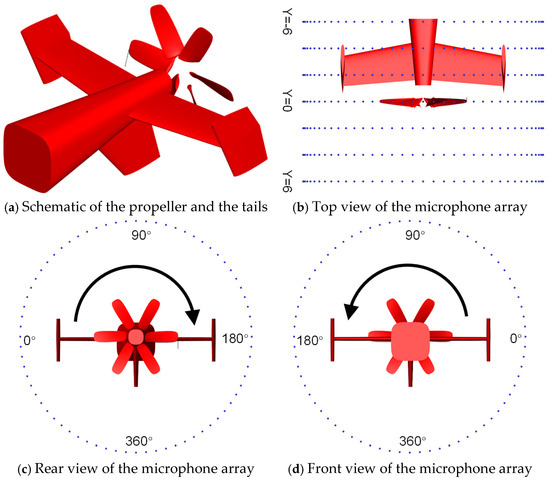
Figure 10.
The simulation model of the microphone array.
Figure 10b–d illustrates the layout and parameters of the acoustic probe array. To comprehensively measure the acoustic directivity and sound pressure distribution of the pusher propeller under the influence of vertical/horizontal tails, a total of 504 microphones are arranged in a cylindrical array, with the array’s central axis coinciding with the rotor hub center of the pusher propeller. The radial distance from each microphone to the rotor hub center is set to 2.75R, where R denotes the propeller radius. The 504 microphones are divided into 7 subgroups, with 72 microphones in each subgroup. The subgroups are uniformly distributed along the circumferential direction of the cylinder at intervals of 5°, covering the full 360° circumferential range to capture the azimuthal variation of acoustic directivity. In the axial direction of the cylinder, the 7 subgroups are positioned at Y-coordinates of −6, −4, −2, 0, 2, 4, and 6 (normalized by the propeller chord length), providing multi-dimensional data support for analyzing the spatial distortion of propeller noise induced by vertical/horizontal tails.
Figure 11 shows the detailed geometry of the vertical and horizontal tails. All values are normalized by the pusher propeller chord length. The vertical tail with a downward extension for rear wheel mounting and the three horizontal tails are formed by spanwise extrusion of the NACA0012 airfoil.
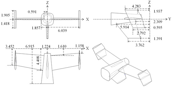
Figure 11.
The geometrical details of the vertical/horizontal tails.
3.2. Distortion Characteristic of the Acoustic Waves
Figure 12 presents the instantaneous acoustic waves of the four-blade pusher propeller, captured in three cross-sectional slices from different directions. The pusher propeller has a blade tip Mach number of 0.665, with a blade angle of 12° at the 0.75R spanwise position. To eliminate interference from the freestream convection effect on the analysis, the propeller’s advance ratio is set to zero in this section. In the free-field environment, the acoustic waves exhibit distinct symmetry characteristics. The X–Z plane shows central symmetry relative to the propeller’s rotational axis, while the acoustic waves in the X–Y and Y–Z planes display left–right symmetry. By contrast, in the scattering environment obstructed by the vertical/horizontal tails, the acoustic waves lose symmetry, and significant distortion occurs. Due to the reflection, scattering, and diffraction effects of the vertical and horizontal tails, as well as the interference between acoustic waves, it can be observed from the X = −0.15 plane that there is a reduction in sound wave intensity on the outside of the vertical tails; from the Z = 0 plane, it can be observed that the acoustic waves above the fuselage deflect slightly towards the rear of the pusher propeller; and from the Y = −2.739 plane, it is evident that the acoustic wavefronts are disrupted, accompanied by the generation of short waves and the concentration of acoustic energy in specific directions. However, one can infer that the wavefronts of the acoustic waves in the X–Y and Y–Z planes remain continuous.
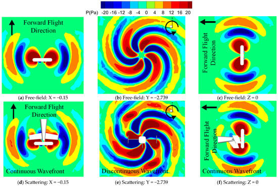
Figure 12.
Instantaneous acoustic waves in three different directions.
Figure 13 shows the instantaneous acoustic waves of the four-blade propeller in the X–Z plane across various Y positions. The acoustic spiral branches in the figure are numerically labeled, where identical numbers signify that the labeled branches are originally part of a single acoustic wave. It is observed that the undisturbed acoustic waves exhibit continuous propagation characteristics, while the wavefronts of disturbed acoustic waves undergo rupture and break into several discrete segments, which are thus defined as short acoustic waves. In the free-field environment, the acoustic energy in the Y = −6 plane is slightly higher than that in the Y = 6 plane. In the scattering field, the acoustic energy in the Y = −6 plane is obviously higher than that in the Y = 6 plane. To facilitate a more intuitive observation of the acoustic waves’ propagation, each distinct wavefront in the figure below is numbered with a single digit. As can be seen, the acoustic waves in the X–Z planes are notably affected by the multiple-reflection effect of the vertical and horizontal tails, as well as the mutual interference of the reflected waves, ultimately leading to the formation of numerous high-intensity short acoustic waves. At the Y = −2.739 slice, due to the installation effect, the originally continuous acoustic wave branch ② is split into two short waves, and the originally continuous acoustic wave branch ① is split into three short waves.
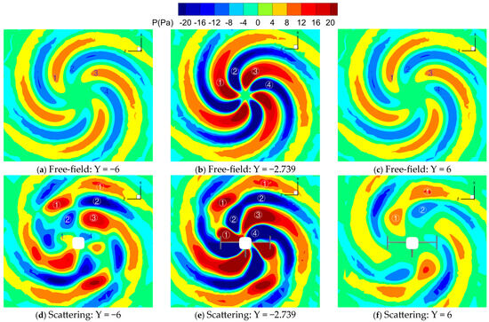
Figure 13.
Instantaneous acoustic waves in the X–Z plane (four-blade propeller).
Figure 14 shows the instantaneous acoustic waves of the six-blade propeller in the X–Z plane at various Y positions. The blade tip Mach number of the pusher propeller is 0.6 with an angle of 24° at 0.75R. Compared with the acoustic waves of the four-blade propeller in Figure 13, one distinction is that six wave branches can be observed in Figure 14. Each distinct acoustic wave in the figure below is also numbered with a single digit. Beyond this wave branch difference, the acoustic behaviors of the six-blade and four-blade rotors in a uniform field also show notable disparities: the four-blade rotor features highly similar acoustic waves at the Y = 6 and Y = −6 slices, while the acoustic energy of the six-blade rotor at the Y = 6 slice is significantly higher than that at the Y = −6 slice. The acoustic waves in the scattering field are seriously affected by the multiple-reflection effect of the tails and the mutual interaction of the reflected waves, and numerous short waves are induced. At the Y = −2.739 slice, due to the installation effect, the originally continuous acoustic wave branch ② is split into three short waves, and the originally continuous acoustic wave branch ① is split into four short waves. Compared with the scattering field of the four-blade propeller, more short acoustic waves can be observed in the acoustic field of the six-blade propeller. The multiple-reflection effect induces a distinct acoustic directivity, causing the concentration of the acoustic energy in four specific areas on the Y = −6 plane.
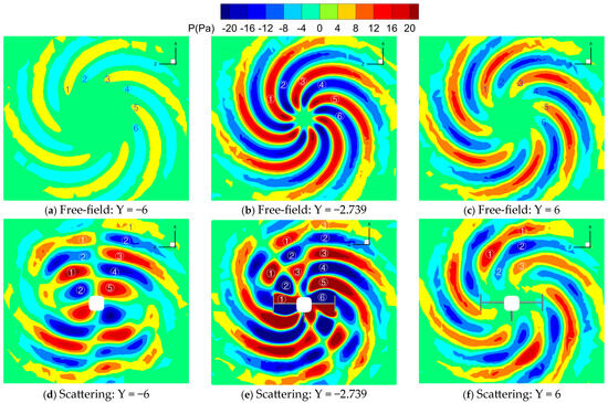
Figure 14.
Instantaneous acoustic waves in the X–Z plane (six-blade propeller).
3.3. Alteration of the Acoustic Directivity
Figure 15 and Figure 16 illustrate the acoustic directivity of the four-blade pusher propeller in the X–Z plane across various Y positions. For comparative analysis, the results corresponding to three cases with distinct blade tip Mach numbers are presented in Figure 15. First, it is evident that the acoustic characteristics in the free field do not have a preferential direction. Moreover, the overall sound pressure level (SPL) increases with an increase in the blade tip Mach number of the pusher propeller, reflecting a positive correlation between these two parameters. Second, in contrast with the free field, the acoustic directivity of the pusher propeller in the scattering field is significantly altered. The patterns of such acoustic directivity alterations exhibit a weak correlation with the blade tip Mach number of the pusher propeller. Furthermore, the magnitude of change in acoustic energy varies substantially across different slices. Among the three target slices (Y = −6, Y = 0, and Y = 6), because the tails reflect acoustic waves toward the forward-flight direction, the acoustic energy in the Y = −6 slice undergoes the most prominent changes, thereby inducing an increase in acoustic energy within this slice at most circumferential azimuthal angles. In contrast, because the oblique reflection effect is induced by the vertical/horizontal tails, the acoustic energy decreases at most circumferential azimuthal angles in the Y = 6 slice. Furthermore, it can be seen from the figures that the maximum variation in SPL reaches 10 dB at local azimuths due to the installation effect.
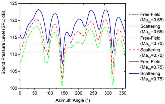
Figure 15.
Pusher propeller acoustic distributions under different blade tip Mach numbers in the X–Z plane with Y = −6 (four-blade propeller).
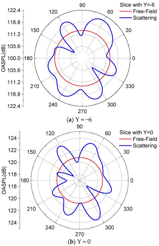
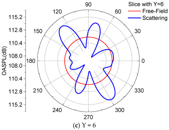
Figure 16.
Acoustic directivity in the X–Z plane (four-blade propeller, Matip = 0.65).
Figure 17 shows the acoustic directivity of the six-blade propeller in the three X–Z planes, while the corresponding instantaneous acoustic waves are depicted in Figure 14. For the slice at Y = −6, the acoustic energy experienced a significant increase as a result of the multiple-reflection effect of the tails and the mutual interaction between the acoustic waves, resulting in a maximum overall sound pressure level increase of 14 dB at around 60°, 135°, 225°, and 300°. The acoustic energy at around 0° and 180° is slightly reduced due to the blocking effect of the vertical tail. For the slice with Y = 6, the acoustic energy in most orientations is reduced due to the blocking effect of the tails on the propagation of the acoustic waves, especially in the upper-right and lower-left corners. For the slice with Y = 0, four regions with high acoustic intensity are formed due to the influence of the vertical/horizontal tails. The azimuthal angle of these regions is approximately 105°, 140°, 280°, and 310°, respectively, corresponding to the four clusters of acoustic waves with shorter lengths in the upper-left and lower-right corners.
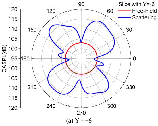
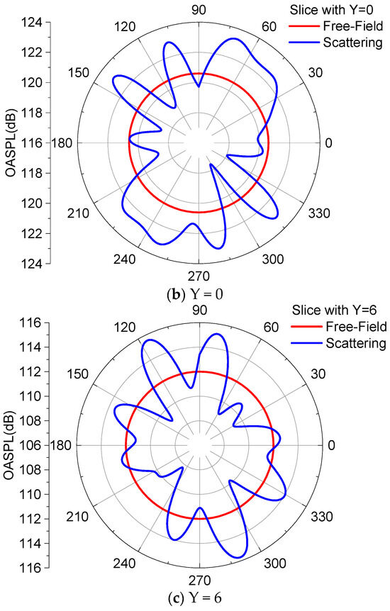
Figure 17.
Acoustic directivity in the X–Z plane (six-blade propeller, Matip = 0.65).
3.4. Transient Propagation Process of Acoustic Waves
Figure 18 presents the transient acoustic waves of the four-blade propeller at four time instants in the X–Z plane with Y = −2.739. Each distinct acoustic wave in this figure is numbered with a single digit, and the acoustic paths with energy valleys and energy peaks are presented. By referring to Figure 13, Figure 15, and Figure 16, it can be inferred that the acoustic directivity is primarily influenced by the oblique reflection effect of the vertical/horizontal tails and the mutual interactions between different acoustic waves. The downward vertical tail in the middle has a smaller impact on the propagation of propeller noise compared with the horizontal tail and the vertical tails installed at the tip of the horizontal tail. The entire interaction process can be decomposed into the following three steps: (1) the acoustic waves are reflected when they interact with the tails; (2) the reflected acoustic waves interact with the subsequently arriving first acoustic wave, and the propagation direction of the subsequently arriving first acoustic wave is altered, resulting in an increase in acoustic energy at about 120° and a decrease in acoustic energy at about 142°. Meanwhile, a short acoustic wave is formed in this interaction process; (3) the acoustic wave with altered propagation direction affects the subsequently arriving second acoustic wave, leading to an increase in the acoustic energy at about 75°. Besides, due to the mutual interaction between the acoustic waves, the reflected acoustic waves are compressed by the subsequently arriving first acoustic waves, leading to the diffraction of the reflected acoustic waves at the tip of the vertical tail. It is worth pointing out that the alteration mechanism of the acoustic directivity in the ranges 180–360° and 0–180° is identical.
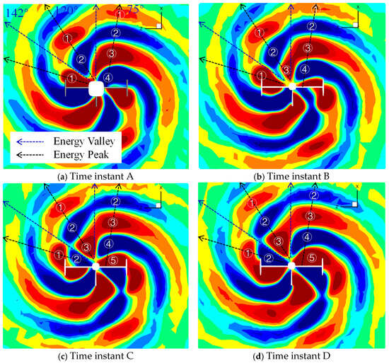
Figure 18.
Transient acoustic waves at different time instants in the X–Z plane (four-blade propeller, Matip = 0.65).
Figure 19 presents the transient acoustic waves of the six-blade propeller at four time instants in the X–Z plane. Each distinct acoustic wave in this figure is numbered with a single digit, and the acoustic paths with energy valleys and energy peaks are also presented. As illustrated above, these acoustic waves with shorter lengths are formed due to the multiple-reflection effect of the tails and the mutual interaction between the acoustic waves. By referring to Figure 14, Figure 17, and Figure 19, it can be observed that the formation process can be decomposed into the three steps as follows: (1) the acoustic waves interact with the tails and are then reflected, resulting in the formation of acoustic waves with shorter lengths at around 140°; (2) the newly formed acoustic waves interact with the subsequently arriving first acoustic wave, resulting in the formation of the second acoustic waves with shorter lengths at around 105°; (3) the acoustic waves with shorter lengths at around 105° interact with the subsequently arriving second acoustic wave, resulting in an increase in acoustic energy at the upper-right corner. Compared with the four-blade propeller, most of the acoustic energy is reflected, and the energy of the diffraction acoustic waves at the tip of the vertical tail occupies only a small portion, resulting in the reduction of the acoustic energy at an orientation of around 180°.
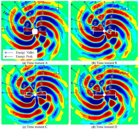
Figure 19.
Transient acoustic waves at different time instants in the X–Z plane (six-blade propeller, Matip = 0.65).
3.5. Alteration of the Acoustic Power Spectrum
Figure 20 shows the overall sound pressure (left column) and the delta sound pressure at the first three harmonic orders (right column) for the four-blade rotor. The delta sound pressure is obtained by subtracting the corresponding components of the SPL in the free field from the components of the SPL in the scattered field at different harmonics. Firstly, it can be observed from the figure that the directivity of the overall sound pressure and the directivity of the first harmonic order exhibit a high degree of similarity, indicating that the effect of the vertical/horizontal tails on the propeller noise is dominated by the alteration of the first-order harmonic noise. Secondly, it can be observed from the figure that the alteration period of the second-order harmonic noise is approximately half of the alteration period of the first-order harmonic noise, indicating that the interaction pattern of the tails on the propeller acoustic is highly correlated with the harmonic orders. In the same space where only one wave exists for the first-order harmonic noise, there are now two independent waves for the second-order harmonic noise. The two waves and the reflected waves interact mutually, resulting in the multiple alternating changes of peaks and valleys in acoustic directivity. Thirdly, as observed from the figure, the second-order and third-order harmonic noises are significantly influenced by the multiple-reflection effect of the tails and the mutual interactions between acoustic waves, leading to a notable change in the sound pressure level. However, these components of acoustic noise do not play a dominant role in determining the final acoustic directivity due to their relatively lower basic energy compared with that of the first harmonic order.
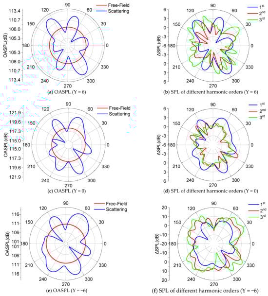
Figure 20.
Acoustic directivity of different harmonic orders in the X–Z plane (four-blade propeller).
4. Conclusions
The TENO-P scheme and the SA-DDES turbulence model are incorporated into the CLORNS solver, and a novel continuous and conserved acoustic source extraction method is proposed and incorporated into our HCAA solver for solving the inconsistency between the evolution time of the flowfield and the time of the acoustic propagation. Then, the effect of the vertical/horizontal tails on the pusher propeller noise is numerically investigated using the improved solvers, and the distortion characteristics and mechanism of the propeller noise are revealed. The detailed conclusions are as follows:
- (1)
- The improved CFD solver is verified by the aerodynamic data of the BO-105 model rotor. The intricate multi-scale vortex structures are well resolved, and the predicted results show good alignment with the experimental data. The novel continuous and conserved acoustic source extraction method is incorporated into the HCAA solver to reduce the non-physical waves on the one-way CFD–CAA coupling surface. The efficacy of the HCAA solver is confirmed through noise data from the SR2 propeller, with the results in this study showing closer alignment with the experimental data compared with the reference data predicted by the FW-H equation.
- (2)
- The instantaneous acoustic waves and the acoustic directivity of the pusher propeller under the influence of the vertical/horizontal tails are numerically investigated. The alteration patterns of acoustic directivity from four-blade and six-blade pusher propellers exhibit significant differences, which indicates that the distortion effect is highly correlated with the number of blades. Conversely, the alteration patterns of acoustic directivity are weakly correlated with the blade tip Mach number of the pusher propeller.
- (3)
- Strong multiple-reflection effects of the acoustic waves happen when they interact with the vertical/horizontal tails. For the four-blade propeller, the reflected acoustic waves interacted with the subsequently arriving first acoustic wave, leading to the formation of one short acoustic wave with a high intensity. For the six-blade propeller, two short waves are generated. The first short acoustic wave with high intensity is generated when the acoustic wave is reflected by the vertical/horizontal tails, and the second short acoustic wave is then generated due to the mutual interaction between the first short wave and the subsequently arriving first acoustic wave.
- (4)
- For the four-blade propeller, due to the mutual interaction between the acoustic waves, the reflected acoustic waves are compressed by the subsequently arriving first acoustic waves, leading to the diffraction of the reflected acoustic waves at the tip of the vertical tail. For the six-blade propeller, most of the acoustic energy is reflected, so the energy of the diffraction acoustic waves occupies only a small portion when compared with the four-blade propeller. The interaction pattern of the tails on the propeller acoustic is highly correlated with the harmonic orders, and the effect of the vertical/horizontal tails on the propeller noise is dominated by the alteration of the first-order harmonic noise.
Author Contributions
Conceptualization, T.Y. and X.C.; methodology, T.Y., X.C., and Q.Z.; software, T.Y., X.C., and Q.Z.; validation, T.Y. and X.G.; formal analysis, T.Y. and L.M.; investigation, T.Y.; resources, T.Y.; data curation, T.Y.; writing—original draft preparation, T.Y. and X.G.; writing—review and editing, T.Y. and X.G.; visualization, T.Y. and X.G.; supervision, X.C., L.M., X.Z., and Q.Z.; project administration, X.C., L.M., X.Z., and Q.Z.; funding acquisition, T.Y. and Q.Z. All authors have read and agreed to the published version of the manuscript.
Funding
This study was supported by the Foundation of National Key Laboratory of Helicopter Aeromechanics (2025-JCJQ-LB-055-08), the National Natural Science Foundation of China (Nos. 12502306 and 12032012), the Foundation of Rotor Aerodynamics Key Laboratory (RAL202403-1), and the China Postdoctoral Science Foundation under Grant Number 2025M784336.
Data Availability Statement
All data generated or analyzed during this study are included in this article.
Conflicts of Interest
The authors declare that they have no known competing financial interests or personal relationships that could have appeared to influence the work reported in this paper.
Abbreviations
The following abbreviations are used in this manuscript:
| CLORNS | Chinese Laboratory of Rotorcraft Navier-Stokes |
| TENO-P | Perturbed polynomial reconstructed Targeted Essentially Non-Oscillatory scheme |
| SA-DDES | Delayed Detached Eddy Simulation based on Spalart–Allmaras |
| CFD–CAA | Computational Fluid Dynamics and Computational AeroAcoustics |
| ABC | Advancing blade concept |
| X2TD | X-2 Technology Demonstrator |
| CFD/CSD | Computational Fluid Dynamics and Computational Structural Dynamics |
| OASPL | OverAll sound pressure level |
| FW-H | Ffowcs–Williams–Hawkings |
| CAA | Computational AeroAcoustics |
| DDES | Delayed Detached Eddy Simulation |
| SA | Spalart–Allmaras |
| RANS | Reynolds-Averaged Navier-Stokes |
| LES | Large Eddy Simulation |
| RKDG | Runge–Kutta Discontinuous Galerkin |
| LEE | Linearized Euler equations |
References
- Hyeonsoo, Y. Design and aeromechanics investigation of compound helicopters. Aerosp. Sci. Technol. 2019, 88, 158–173. [Google Scholar] [CrossRef]
- Zhang, T.; Barakos, G.; Furqan; Foster, M. High-fidelity aerodynamic and acoustic design and analysis of a heavy-lift eVTOL. Aerosp. Sci. Technol. 2023, 137, 108307. [Google Scholar] [CrossRef]
- Yuan, Y.; Chen, R.; Thomson, D. Propeller design to improve flight dynamics features and performance for coaxial compound helicopters. Aerosp. Sci. Technol. 2020, 106, 106096. [Google Scholar] [CrossRef]
- Charles, C.; Crawford, J.R. Noise Requirements from a Military Point of View; U.S. Army Aviation Research and Development Command: Huntsville, AL, USA, 1978. [Google Scholar]
- Qi, H.; Xu, G.; Lu, C.; Shi, Y. A study of coaxial rotor aerodynamic interaction mechanism in hover with high-efficient trim model. Aerosp. Sci. Technol. 2019, 84, 1116–1130. [Google Scholar] [CrossRef]
- Yuan, X.; Bian, W.; Zhao, Q.; Zhao, G. Numerical investigation of aerodynamic interactions for the coaxial rotor system in low-speed forward flight. Aerosp. Sci. Technol. 2024, 149, 109148. [Google Scholar] [CrossRef]
- Jia, Z.; Lee, S. Aerodynamically induced noise of a lift-offset coaxial rotor with pitch attitude in high-speed forward flight. J. Sound Vib. 2021, 491, 115737. [Google Scholar] [CrossRef]
- Jia, Z.; Lee, S. Impulsive loading noise of a lift-offset coaxial rotor in high-speed forward flight. AIAA J. 2020, 58, 687–701. [Google Scholar] [CrossRef]
- Zhong, S.; Ma, Z.; Zhou, P.; Wu, H.; Zhang, X. Predicting the aerodynamic noise of counter-rotating coaxial rotors. J. Sound Vib. 2023, 547, 117487. [Google Scholar] [CrossRef]
- Xu, P.; Peng, J.; Bai, J.; Han, X.; Song, W. Aeroacoustic and aerodynamic optimization of propeller blades. Chin. J. Aeronaut. 2020, 33, 826–839. [Google Scholar] [CrossRef]
- Pagano, A.; Barbarino, M.; Casalino, D.; Federico, L. Tonal and broadband noise calculations for aeroacoustic optimization of a pusher propeller. J. Aircr. 2010, 47, 835–848. [Google Scholar] [CrossRef]
- Chiaramonte, J.; Favier, D.; Maresca, V.; Benneceur, S. Aerodynamic interaction study of the propeller/wing under different flow configurations. J. Aircr. 1996, 33, 46–53. [Google Scholar] [CrossRef]
- Yin, J.; Stuermer, A.; Aversano, M. Aerodynamic and aeroacoustic analysis of installed pusher-propeller aircraft configurations. J. Aircr. 2012, 49, 1423–1433. [Google Scholar] [CrossRef]
- Soderman, P.T.; Horne, W.C. Acoustic and Aerodynamic Study of a Pusher-Propeller Aircraft Model; NASA Technical Paper 3040; NASA: Washington, DC, USA, 1990.
- Sun, D.; Chen, X.; Zhao, Q.; Bao, W. Numerical analyses of aerodynamic and aeroacoustic interaction characteristics of rear-mounted propeller on highspeed helicopter. Aerospace 2025, 12, 343. [Google Scholar] [CrossRef]
- Redonnet, S.; Desquesnes, G.; Manoha, E. Numerical study of acoustic installation effects with a computational aeroacoustics method. AIAA J. 2010, 48, 929–937. [Google Scholar] [CrossRef]
- Redonnet, S. Investigation of the acoustic installation effects of an open-jet anechoic wind tunnel using computational aeroacoustics. Appl. Acoust. 2020, 169, 107469. [Google Scholar] [CrossRef]
- Redonnet, S.; Lockard, D.P.; Khorrami, M.R.; Choudhari, M.M. The non-reflective interface: An innovative forcing technique for computational acoustic hybrid methods. Int. J. Numer. Methods Fluids 2016, 81, 22–44. [Google Scholar] [CrossRef]
- Terracol, M.; Manoha, E.; Herrero, C.; Labourasse, E.; Redonnet, S.; Sagaut, P. Hybrid methods for airframe noise numerical prediction. Theor. Comput. Fluid Dyn. 2005, 19, 197–227. [Google Scholar] [CrossRef]
- Yang, T.; Chen, X.; Zhao, Q.; Ding, Y. Numerical analysis on the high-speed impulsive noise propagation characteristic of helicopter rotor in the presence of strong shear flow. Appl. Acoust. 2023, 203, 109213. [Google Scholar] [CrossRef]
- Yang, T.; Chen, X.; Zhao, Q.; Zhao, G. Numerical study on the noise propagation characteristics of rotor in non-uniform downwash flowfield based on linearized Euler equations. Int. J. Aeroacoustics 2022, 21, 731–765. [Google Scholar] [CrossRef]
- Yang, T.; Zhao, G.; Zhao, Q. Novel TENO schemes with improved accuracy order based on perturbed polynomial reconstruction. J. Comput. Phys. 2023, 488, 112219. [Google Scholar] [CrossRef]
- Zhao, Q.; Xu, G. A study on aerodynamic and acoustic characteristics of advanced tip-shape rotors. J. Am. Helicopter Soc. 2007, 52, 201–213. [Google Scholar] [CrossRef]
- Zhao, Q.; Zhao, G.; Wang, B.; Wang, Q.; Shi, Y.; Xu, G. Robust Navier-Stokes method for predicting unsteady flowfield and aerodynamic characteristics of helicopter rotor. Chin. J. Aeronaut. 2018, 31, 214–224. [Google Scholar] [CrossRef]
- Chen, X.; Zhang, K.; Zhao, Q.; Wang, W. Numerical analysis of rotor aeroacoustics characteristics during collective pitch aperiodic variation in hover. Aerosp. Sci. Technol. 2022, 124, 107411. [Google Scholar] [CrossRef]
- Vatsa, V.; Lockard, D.; Spalart, P. Grid sensitivity of SA-based delayed-detached-eddy-simulation model for blunt-body flows. AIAA J. 2017, 55, 2842–2847. [Google Scholar] [CrossRef]
- Liu, J.; Chen, J.; Xiao, Z. Improvements for the DDES model with consideration of grid aspect ratio and coherent vortex structures. Aerosp. Sci. Technol. 2024, 151, 109314. [Google Scholar] [CrossRef]
- Yang, X.; Yang, A.; Si, J. Efficient numerical techniques for simulation of rotorcraft flow field with overlap grids. AIAA J. 2015, 53, 1372–1383. [Google Scholar] [CrossRef]
- Yang, X.; Griffin, K. Grid-point and time-step requirements for direct numerical simulation and large-eddy simulation. Phys. Fluids 2021, 33, 015108. [Google Scholar] [CrossRef]
- Gennaretti, M.; Bernardini, G.; Serafini, J.; Romani, G. Rotorcraft comprehensive code assessment for blade-vortex interaction. Aerosp. Sci. Technol. 2018, 80, 232–246. [Google Scholar] [CrossRef]
- You, Y.; Na, D.; Jun, S. Improved rotor aeromechanics predictions using a fluid structure interaction approach. Aerosp. Sci. Technol. 2018, 73, 118–128. [Google Scholar] [CrossRef]
- Romani, G.; Casalino, D. Rotorcraft blade-vortex interaction noise prediction using the Lattice-Boltzmann method. Aerosp. Sci. Technol. 2019, 88, 147–157. [Google Scholar] [CrossRef]
- Kotwicz Herniczek, M.T.; Feszty, D.; Meslioui, S.A.; Park, J.; Nitzsche, F. Evaluation of acoustic frequency methods for the prediction of propeller noise. AIAA J. 2019, 57, 2465–2478. [Google Scholar] [CrossRef]
- Tan, C.H.; Voo, K.S.; Siauw, W.L.; Alderton, J.; Boudjir, A.; Mendonça, F. CFD analysis of the aerodynamics and aeroacoustics of the NASA SR2 propeller. In Proceedings of the ASME Turbo Expo 2014: Turbine Technical Conference and Exposition, Düsseldorf, Germany, 16–20 June 2014. [Google Scholar]


Disclaimer/Publisher’s Note: The statements, opinions and data contained in all publications are solely those of the individual author(s) and contributor(s) and not of MDPI and/or the editor(s). MDPI and/or the editor(s) disclaim responsibility for any injury to people or property resulting from any ideas, methods, instructions or products referred to in the content. |
© 2026 by the authors. Licensee MDPI, Basel, Switzerland. This article is an open access article distributed under the terms and conditions of the Creative Commons Attribution (CC BY) license.