Abstract
This study introduces the Gyroid structure, a type of triply periodic minimal surface (TPMS), for enhanced effusion cooling performance. Conjugate heat transfer simulations are used to compare the flow behavior, pressure loss, and overall cooling effectiveness of single- and double-wall Gyroid configurations against a baseline film hole model at blowing ratios of 0.5–2.0. Results show that the Gyroid design eliminates jet lift-off and counter-rotating vortex pairs, ensuring full coolant coverage and a thicker coolant layer than the baseline. The double-wall configuration further improves cooling with jet impingement, yielding higher average Nusselt numbers than the single-wall design. At equal pressure loss, the impingement/Gyroid model outperforms the baseline by 102.7% in cooling effectiveness. To assess manufacturability, a high-resolution CT scan is used to validate a laser powder bed fusion-printed Gyroid sample at gas turbine blade scale, confirming feasibility for industrial application. These findings highlight the superior thermal performance and manufacturability of the 3D-printed Gyroid structure, offering a promising cooling solution for next-generation turbine blades.
1. Introduction
Gas turbines are widely used for aircraft propulsion and industrial applications. To enhance power and efficiency, turbine inlet temperatures have been steadily increased, necessitating advanced cooling technologies for gas turbine blades. Traditional cooling methods, such as jet impingement, rib turbulators, pin fins, and film cooling holes, have limited effectiveness and high cooling air consumption [1,2,3,4,5]. Consequently, conventional cooling systems struggle to meet the demands of modern gas turbines, reducing their competitiveness.
Transpiration cooling is a highly efficient thermal protection technology in aerospace applications [6]. Theoretically similar to effusion cooling, transpiration cooling occurs when the hole diameter and spacing are sufficiently small. While effusion cooling employs a plate with multiple rows of film cooling holes, transpiration cooling typically uses porous materials. Due to its superior performance, transpiration cooling represents a significant advancement in gas turbine cooling.
The principle of transpiration cooling is illustrated in Figure 1a. A porous solid matrix is first cooled via convective heat transfer as coolant flows through its pores. The discharged coolant forms a protective film on the surface, shielding it from the mainstream hot gas. The high internal convective cooling efficiency arises from the large surface area-to-volume ratio of the porous media. Additionally, the uniform distribution of pores ensures effective heat transfer, maximizing the heat absorption capacity of the coolant. As a result, transpiration cooling outperforms conventional methods [2].
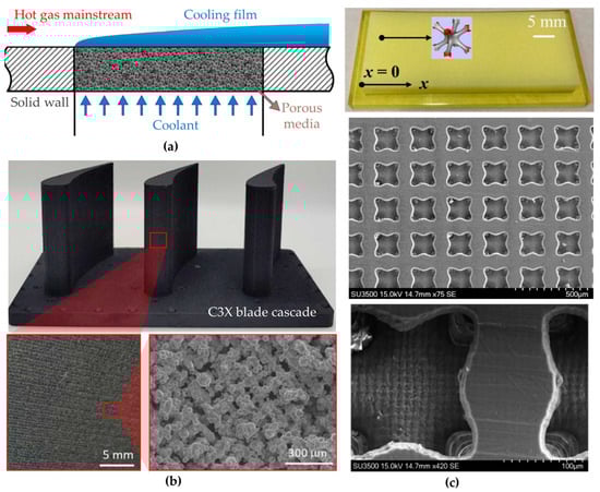
Figure 1.
Transpiration cooling studies: (a) Sketch of traditional transpiration cooling principle; (b) Metal 3D-printed gas turbine blade with porous-based transpiration cooling structure (Reproduced with permission from [7]. Copyright 2022 Elsevier) and (c) Cellular-based transpiration cooling (Reproduced with permission from [8]. Copyright 2023 Elsevier).
However, implementing transpiration cooling in gas turbine blades presents structural and manufacturing challenges. Recent studies suggest sintered metal models as cost-effective, high-permeability solutions. Coolant flow rate and porous media properties significantly influence performance. Liu et al. [9] found that porous bronze provides more uniform cooling than stainless steel, while Xu et al. [10] demonstrated that a 55%-porosity woven mesh greatly enhances efficiency. Hinse et al. [11] observed that pore size has minimal impact when porosity is high. At high flow rates, cooling efficiency can improve by up to 200% compared to conventional methods.
Additive manufacturing (AM) enables complex transpiration cooling designs with minimal material waste and high efficiency [12,13,14,15]. Recent studies also optimized the tool to improve the quality of the 3D-printed model, which was promising to obtain highly accurate printing results [16,17,18,19]. The current AM-fabricated structures exhibited greater tensile strength than sintered counterparts [20], although they might modify the flow characteristics and heat transfer performance due to the inherent increased roughness [21,22]. Tests on 3D-printed C3X turbine blades, as shown in Figure 1b, showed 34% and 25% higher cooling effectiveness than effusion and internal cooling, respectively [7,23]. Xu et al. [24] highlighted the potential of AM in fabricating microporous structures and optimizing transpiration cooling for gas turbine and aerospace applications. Overall, AM offers a promising pathway to develop high-performance transpiration cooling systems, bridging the gap between turbine operating temperatures and blade thermal limits.
Various designs have been explored to enhance transpiration cooling effectiveness. Min et al. [25] evaluated six selective laser metal sintering (SLMS) Inconel 718 designs, finding that a blood-vessel-shaped structure achieved the highest cooling effectiveness by 31.6–39%, surpassing fan-shaped designs. Huang et al. [26] studied bio-inspired structures and identified a porous parallelogram configuration that improved film protection and cooling efficiency. Chyu et al. [27] found that while lattice integration slightly reduces overall cooling effectiveness by obstructing cooling holes, it mitigates losses from pore blockages and provides superior structural support compared to pin-fins due to its high surface-to-footprint ratio. These findings emphasize the critical role of pore topology in cooling performance [28].
Cellular lattices based on the triply periodic minimal surface (TPMS), such as Gyroid, Diamond, I-graph, and wrapped package (IWP), are emerging as promising solutions for gas turbine blade cooling. Heat transfer in these structures is increased due to strong turbulence generation [14,29]. Yeranee and Rao [30] reported that sheet-Gyroid designs improved thermal performance by 72.7% over pin-fin arrays. Additionally, the TPMS design reduced rotational effects and thermal stress [31,32]. Optimized TPMS structures in serpentine channels increased heat transfer while lowering pressure loss, improving thermal performance by 64.8% [33]. The TPMS structures as a pedestal in double-wall cooling channels also demonstrated higher cooling effectiveness, reduced pressure loss, and strengthened the structural integrity [34,35].
TPMS networks have also been applied to transpiration cooling. Cheng et al. [8] compared uniform and graded transpiration plates based on IWP networks, as shown in Figure 1c, finding that graded IWP improved temperature uniformity and reduced hot spots. Broumand et al. [36] demonstrated that Diamond-based transpiration cooling achieved five times higher adiabatic film cooling effectiveness than conventional film holes. Son et al. [37] evaluated various TPMS topologies and found that the Koch orientation exhibited minimal sensitivity to film cooling effectiveness, making it suitable for complex surfaces exposed to directional flows.
Despite these advances, research on the overall cooling effectiveness of TPMS-based transpiration cooling remains limited. Given this gap, this study investigates Gyroid-based TPMS structures for high-performance effusion cooling, leveraging their superior heat transfer and mechanical properties [12,13,14]. Impingement/effusion cooling designs are developed by integrating a jet impingement plate into all models. Using conjugate heat transfer simulations, the flow characteristics, pressure loss, and overall cooling effectiveness of the Gyroid effusion cooling unit and a baseline film hole model are compared at blowing ratios (BRs) of 0.5–2.0. Moreover, high-resolution CT scanning is used to assess the manufacturability of the Gyroid effusion sample, ensuring feasibility for industrial implementation.
2. Methodology
2.1. Numerical Model
The unit model used in this study is derived from the film-cooling section of a gas turbine blade, as shown in Figure 2. Since film-cooling holes are typically arranged in streamwise and spanwise directions on turbine blades, the downstream wall in this investigation is designed to be shorter than those used in various other film-cooling studies that focus on the adiabatic film cooling effectiveness [38]. Several film-cooling studies have employed similar unit configurations [39,40].
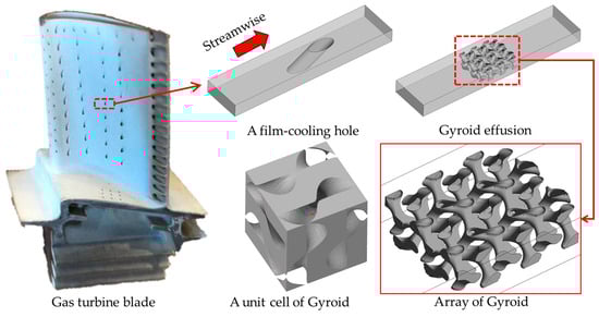
Figure 2.
Design of unit models in this study.
For the unit configuration of the TPMS structures, the 3 × 3 × 1 in length, width, and height of the Gyroid unit cells are embedded in the same size wall as a film-cooling hole model. It is important to note that although these structures are periodic, all sides are asymmetric. Additionally, partition walls are incorporated on the side walls to enhance the structural integrity. These partition walls improve the mechanical property without deteriorating the cooling efficiency [20]. With the partition walls and nature of the TPMS structure, asymmetric flow patterns are anticipated in the Gyroid model.
Figure 3 shows the numerical model of the single- and double-wall unit configurations for different cooling designs: film hole in Figure 3a and Gyroid-TPMS effusion in Figure 3b. The double-wall configuration includes external and internal plates, while the single-wall one only has an external plate. For all studied configurations, the size of both plates is 2.7 mm × 11.7 mm × 0.9 mm in width, length, and thickness. The diameter of the film hole is 0.9 mm. The hole of the film hole model is tilted at an angle of 30 degrees.
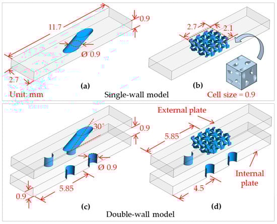
Figure 3.
Numerical models: (a) Film hole; (b) Gyroid; (c) Impingement/film, and (d) Impingement/Gyroid.
Meanwhile, the Gyroid structure is generated using MSlattice [41] at the unit cell size of 0.9 mm and a designed unit cell porosity of 3.0%, yielding the smallest hole size of around 0.2 mm. It is important to distinguish between the porosity of an individual unit cell and the effective porosity of the entire manufactured plate. When these unit cells, with a size of 2.1 mm × 2.7 mm in width and length, are integrated into the external plate design, the effective porosity of the final Gyroid external plate is 5.12%, as reported in Table 1. The effective porosity of the Gyroid model of 5.12% is selected to match current powder bed fusion printable capabilities, which has been used to fabricate complex geometry transpiration plates for gas turbine blade cooling research [8,25]. Although the film hole and Gyroid models have similar porosity, the Gyroid design provides an internal surface area that is more than 5 times larger than the film hole model, implying much higher internal cooling [12,13,14]. This provides a fair comparison for real-world applications, highlighting the realistic performance improvements from the Gyroid effusion cooling.

Table 1.
Summary of the configurations of the external plate in this study.
Furthermore, all double-wall designs in Figure 3c,d have the same configurations as the single-wall ones in Figure 3a,b, with an additional jet impingement on the internal plate. Each jet hole has a diameter of 0.9 mm. The jet holes are arranged in an inline pattern. The streamwise and spanwise spacing is 2.7 mm. The spacing between the internal and external plates is 0.9 mm. The pedestals and cross-flow effects between these plates are excluded in the present study.
2.2. Computational Domain and Boundary Conditions
Ansys Fluent v. 2021R1, Ansys Inc., Canonsburg, Pennsylvania, United States, is utilized to reveal the fluid flow and overall cooling effectiveness (OCE). The conjugate model of the single- and double-wall configurations is depicted in Figure 4. The boundary conditions in this investigation closely resemble those in the experimental study by Nakamata et al. [42] and the numerical simulation by Li et al. [43]. A symmetry boundary is implemented in the spanwise direction to reduce computational costs. Conjugate boundaries are utilized at the interfaces between the solid and fluid domains, while the remaining surfaces are set as adiabatic. Coolant and hot gas are specified by compressible ideal air for the fluid domain. The hot gas inlet boundary is defined by a uniform velocity (Uh) of 84 m/s and a temperature (Th) of 672 K, whereas the coolant inlet boundary is characterized by an inlet mass flow rate within the blowing ratio (BR) of 0.5–2.0 and a temperature (Tc) of 320 K. The outlet boundary is set as a pressure outlet (p = 0). The solid domain is a nickel-based alloy material. The properties within the solid domain can be found in the Appendix A [44].
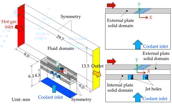
Figure 4.
Computational domain and boundary conditions.
It should be noted that these boundary conditions primarily affect the boundary layer development and the local interaction of the hot gas with the coolant film immediately downstream of the holes, where a turbulent profile yields different near-wall shear stresses and mixing rates [45]. However, for the objective of this study, comparing the relative performance of two cooling schemes under the same controlled conditions, the uniform inlet assumption is a valid and common approach [34,43]. This enables a direct comparison of the flow and heat transfer mechanisms between the Gyroid and conventional film cooling, without introducing confounding variations from specific inlet conditions.
A pressure-based solver is employed for the computational setup. The pressure-velocity coupling is resolved using the Rhie–Chow flux type and the Coupled scheme. Spatial discretization is performed using a second-order upwind scheme to ensure accuracy. Convergence is achieved when the average hot gas inlet pressure, hot gas outlet velocity, and external wall temperature exhibit changes of less than 0.05% over the last 1000 iterations.
2.3. Parameter Definition
The blowing ratio (BR) in this study is calculated as follows:
where ρc and Uc are the density and velocity of the cooling air through the baseline film hole, defined at the coolant inlet. ρh and Uh are the density and velocity of the hot gas, determined at the hot gas inlet. Therefore, this definition provides the identical mass flow rate of the coolant in all designs. Moreover, the Mach number of the hot gas and the coolant is less than 0.3 within the studied BR of 0.5–2.0.
The Nusselt number (Nu) is evaluated to present the cooling performance that influences the heat transfer on the cold-side surface of the external plate. It is defined as follows:
where Dj is the diameter of the jet hole (Dj = 0.9 mm). q is the wall heat flux on the cold-side surface. Tcw is the temperature of the cold-side wall of the external plate, and kf is the thermal conductivity of the fluid.
The overall cooling effectiveness (OCE) is calculated to show the conjugate heat transfer performance on the hot-side surface, which is defined as follows:
where Th is the mainstream temperature, while Thw is the temperature of the hot-side wall of the external plate.
The total pressure loss due to the mixing of coolant with the hot gas and boundary layer is calculated as follows:
where pc,in and ph,in represent the inlet pressure of the coolant and hot gas, while the ph,out is the outlet pressure of the mixture between coolant and hot gas. The
and
are the mass flow rates of the coolant and hot gas.
2.4. Mesh Generation and Computational Scheme
Fluent Meshing is utilized to generate poly-hexagon-shaped and prism-shaped meshes in order to discretize the computational domain. Figure 5 illustrates an example of mesh systems of the double-wall configuration with the Gyroid design. Most elements within the solid and fluid domains are hexagonal elements, while the prism-shaped meshes are densely generated near all the no-slip surfaces to ensure that the y+ values remain below 1.0. Boundary layers occur on symmetry boundaries to facilitate grid generation for the model. These boundaries are later changed to the symmetry condition before calculations. In all models, the target skewness values for the surface and volume mesh are set at 0.8 and 0.96, respectively. It is essential to mention that the SST k-ω turbulence model is employed in this simulation to obtain the most accurate results, as the heat transfer calculated using this turbulence model has shown good agreement with various experimental data [46,47].
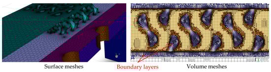
Figure 5.
An overview of the mesh system.
Mesh systems at 3.66 × 10⁶, 4.27 × 10⁶, and 9.43 × 10⁶ elements have been generated for the double-wall configuration with the Gyroid design to assess mesh independence at the BR = 1.0. Figure 6 plots the local temperature in the middle of the hot-side surface of the external plate for different mesh numbers. It could be observed that all mesh systems provide almost identical temperature distributions. The variations in the average temperature in 3.66× 10⁶ and 4.27 × 10⁶ elements compared to the 9.43 × 10⁶ elements are 0.29% and 0.18%, respectively.
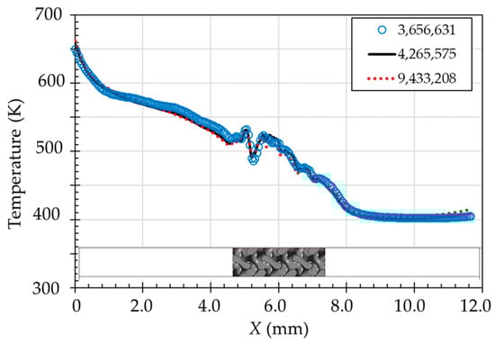
Figure 6.
Temperature distribution in the middle of the hot-side surface in different mesh systems.
The area-averaged Nusselt number on the cold-side wall and area-averaged OCE on the hot-side surface from the mesh systems at 3.66 × 10⁶, 4.27 × 10⁶, and 9.43 × 10⁶ elements are compared. It has been observed that the area-averaged Nusselt number with the mesh of 3.66 × 10⁶ and 4.27 × 10⁶ elements is 0.3–1.2% deviated from the highest resolution mesh (9.43 × 10⁶ elements), while the area-averaged OCE is 0.15–0.44%. Additionally, the average GCI value [48] of the temperature is approximately 1.0%, indicating that the mesh numbers shown in this study have a minimal impact on the results. As the computational time in the mesh of 4.27 × 10⁶ is lower than in the 9.43 × 10⁶ elements, the mesh of 4.27 × 10⁶ elements is chosen for the double-wall configuration with the Gyroid structure to ensure accuracy. The mesh settings are also generated for the other models, including those in the single-wall configuration.
2.5. Validation of the Numerical Method
A comparative analysis is conducted between the numerical results and the IR experimental data provided by Jung et al. [49] at the BR of 0.3 to evaluate the accuracy of the numerical approach employed in this study. The experimental model consists of a film cooling plate that covers the entire surface and a jet impingement plate. This arrangement creates an impingement/effusion cooling system without pedestals. The thickness of the film plate is 2.4 times the diameter of the film hole, while the jet plate thickness is 5.0 times. The film plates are constructed using stainless steel and polycarbonate materials, corresponding to Biot numbers of 0.06 and 4.04, respectively. The distance between the film and the jet impingement plates is equal to the diameter of the film holes. Both the film cooling and jet impingement holes are arranged in a staggered array, with an equal number of holes in each arrangement. The numerical model, which resembles the experimental model by Jung et al. [49], is shown in the Appendix A.
Figure 7 illustrates the comparison of the local OCE obtained from the simulation and the corresponding experimental data at two Biot numbers. The findings reveal a strong correlation between the simulation and experimental results, suggesting that the numerical method employed in this study accurately reproduces the flow and heat transfer characteristics in the unit study of single- and double-wall cooling models.
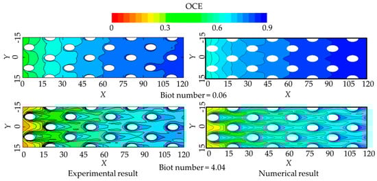
Figure 7.
Contours of the overall cooling effectiveness from Jung et al. [49] and numerical results in this study. Reproduced with permission from [49]. Copyright 2017 Elsevier.
The validations of the present numerical procedure with the experimental results of Jung et al. [49] are shown in Figure 8. A comparison of the average cooling effectiveness across the spanwise direction on the hot-side wall of the external plate is demonstrated in Figure 8a. The numerical results align closely with the experimental data. It is noticeable that the IR results demonstrate smooth increased cooling effectiveness, while the present numerical results exhibit slight fluctuations. This is due to the time-averaged nature of IR thermography measurement, while the simulation computes an instantaneous solution for an idealized system, revealing inherent flow physics. Nevertheless, the mean deviation values at Biot numbers of 0.06 and 4.04 are about 2.29% and 2.59%, respectively.
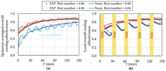
Figure 8.
Validations of the present numerical procedure with the IR experimental data of Jung et al. [49]: (a) Spanwise-averaged cooling effectiveness and (b) Local overall cooling effectiveness.
In addition, the cooling effectiveness on the hot-side wall of the film plate at X = 7.5 mm is illustrated in Figure 8b. The simulations show a slight overestimation compared to the experiments for the investigated Biot numbers. Notably, an apparent deviation is observed at 8 mm < Y < 30 mm due to the unsteady flow patterns resulting from the initial interaction between the hot gas and the coolant released from the holes [34,43]. However, the average deviation values for Biot numbers of 0.06 and 4.04 are 4.63% and 5.15%, respectively. In summary, these findings validate the accuracy and reliability of the numerical approach used in this study, as the deviations fall within an acceptable range.
It should be noted that this validation utilizes a well-established staggered array benchmark to verify the accuracy of the CFD solver, meshing strategy, and turbulence model in this study to predict the flow and heat transfer of film cooling [34,43]. For a single isolated hole, the cooling effectiveness is generally higher than that of the array of film holes because there is no interaction with upstream coolant jets that can disrupt the protective film layer. This explains the overestimation observed in the first row of the validation case. This validation approach, however, finds strong precedent in the previous work [40], where their methodology was also validated against a staggered array before successfully applying it to the heat transfer study of a single impingement/film-cooling structure. Therefore, the agreement of the present model with the established staggered array benchmark [49] could be used to provide fundamental confidence in its applicability to the single-hole geometry in this investigation.
3. Results and Discussion
3.1. Internal Flow and Heat Transfer
This section presents the internal flow and temperature distributions of all models at the BR of 2.0, since the flow and heat transfer patterns are almost identical with the studied BR. Figure 9 shows internal velocity streamlines and temperature distributions on the cold-side wall of the external plate for all models at the BR of 2.0. In single-wall configurations, coolant flow through the holes is driven by the suction effect, which is pressure-driven entrainment due to external flow, resulting in weaker coolant penetration and, consequently, higher cold-side surface temperatures than in double-wall configurations. Among double-wall designs, the film hole model, as shown in Figure 9a, achieves the most pronounced temperature reduction due to intense jet interaction within the channel, which enhances convective heat transfer. In addition, the Gyroid in Figure 9b exhibits stronger suction effects than the film hole model due to its dense and small-hole structures. The large internal surface area of the extraction holes could also play an important role in increasing the Nusselt number [4,5]. However, the Gyroid networks delay jet interaction, reducing peak heat transfer between impingement zones and thus limiting temperature reduction.
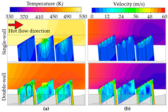
Figure 9.
Internal flow characteristics and temperature distributions at the BR of 2.0: (a) Film hole and (b) Gyroid.
The Nusselt number distributions on the cold-side wall of the external plate for all models at the BR of 2.0 are presented in Figure 10. In single-wall models, large areas of low Nu (Nu < 10) are observed due to the suction effect within the channel. The Gyroid model creates larger regions of high Nu (Nu ≥ 30) compared to the film hole model. Jet impingement significantly increases the Nu at the stagnation zone for double-wall cooling models. As shown in Figure 10a, the film hole model exhibits an expanded high Nu area due to its large wall area and strong jet interaction. In contrast, for the Gyroid network in Figure 10b, the coolant penetrates directly through small holes near the stagnation zones, resulting in high Nu values at the hole edges. However, this effect reduces the intensity of jet interaction, leading to a smaller area of high Nu than the film hole model.
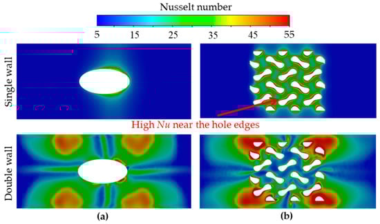
Figure 10.
Nusselt number distributions on the cold-side wall at the BR = 2.0: (a) Film hole and (b) Gyroid.
The area-averaged Nu for all models within the studied BR is plotted in Figure 11. Due to additional jet impingement, the average Nu in the single-wall models is lower than in the double-wall models. The film hole causes the lowest value, and all single-wall designs show increased area-averaged Nu as the BR increases. The area-averaged Nu of the film hole is lower than that of the Gyroid models in the single-wall configuration by 69.3–78.8%, as the BR increases from 0.5 to 2.0. Compared to the single-wall configuration, the double-wall cooling with the film hole shows a significantly increased area-averaged Nu by up to 240.2% at the BR of 2.0 due to enhanced internal cooling from jet interaction without negative cross-flow on the internal plate [3]. This interaction disrupts boundary layer development and significantly induces strong turbulence on the cold-side wall, far exceeding the performance of the single-wall design. Meanwhile, the double-wall cooling with the Gyroid enhances the area-averaged Nu by 61.5–112%. However, the area-averaged Nu of the film hole is still lower than that of the Gyroid model in the double-wall configuration by 7.0–11.4%.
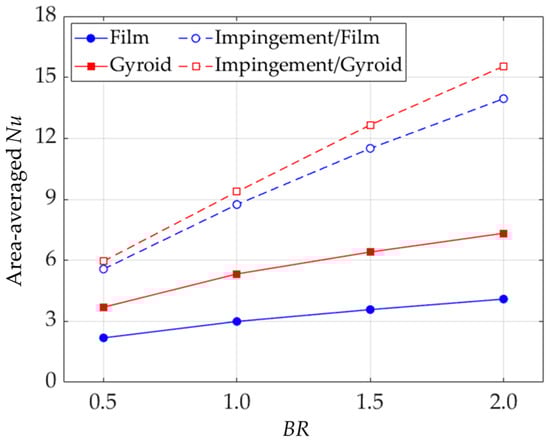
Figure 11.
Area-averaged Nusselt numbers on the cold-side surface of the external plate within the studied BR.
3.2. External Flow and Overall Cooling Effectiveness
This section shows the external flow characteristics and OCE distributions at the BR of 0.5 and 2.0, since the flow interaction between hot gas and coolant depends largely on the coolant velocity. Figure 12 shows the 3D velocity streamlines and vorticity contours on the external plate for all models at the BR of 0.5 and 2.0. As seen in Figure 12a, the coolant strongly discharges from the baseline film hole with high velocity, causing jet lift-off from the external plate. Higher velocity magnitude can be seen when incorporating a jet impingement as double-wall cooling. In addition, the counter-rotating vortex pairs (CRVPs) are observed in the film hole case. The jet lift-off and the CRVPs are more evident at a high BR of 2.0.
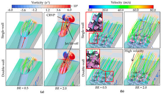
Figure 12.
External flow characteristics at the BR = 0.5 and 2.0: (a) Film hole and (b) Gyroid.
Meanwhile, the flow characteristics in the Gyroid design, as seen in Figure 12b, due to its complex topology, differ from the film model, where the ideal pattern of the film cooling is symmetric, directly generating the CRVPs and pulling the coolant jet to the hot gas [45]. The flow interaction in the Gyroid before discharging minimizes the jet lift-off and disrupts the formation of the CRVPs on the external plate. Jet impingement in the Gyroid model slightly increases the discharged coolant velocity, but the overall flow structure is similar. Interestingly, at a high BR of 2.0, the Gyroid design prevents jet lift-off in both single- and double-wall configurations. Due to its inherently asymmetric topology, this structure induces asymmetric vortical flow patterns. Although the partition walls in the studied design further deflect the discharged coolant, the flow patterns of the Gyroid positively influence both internal and external convective heat transfer, improving cooling effectiveness [37]. Moreover, the Gyroid model creates a thicker and more uniform coolant layer than the conventional film hole model despite high-velocity zones resulting from intense jet impingement within the channel.
The contours of the OCE on the external wall in all models at the BR of 0.5 and 2.0 are demonstrated in Figure 13. Due to the negative effects of jet lift-off and CRVPs in the film hole model, the contour of the OCE is non-uniform, as seen in Figure 13a. At the BR of 0.5 and 2.0, the jet impingement in the film hole model significantly improves the OCE distribution, especially in the upstream channel. In addition, the contours of the OCE in the Gyroid model are almost identical for both the single- and double-wall configurations, as seen in Figure 13b. Particularly at the BR = 2.0, the contours of the OCE nearly reach the value of 1.0 downstream of the Gyroid networks due to the coolant accumulation and enhanced internal cooling due to the large internal surface area. Also, the small holes in the Gyroid model generate flow mixing, resulting in a uniform distribution of the OCE on the external plate.
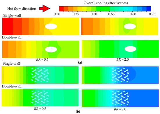
Figure 13.
Overall cooling effectiveness contours on the external plate at the BR = 0.5 and 2.0: (a) Film hole and (b) Gyroid.
The area-averaged OCE of all models within the studied BR is plotted in Figure 14 for the whole external plate. For all models, the OCE value increases as the BR increases. Although the OCE of the film hole is sensitive to the BR, both the single- and double-wall configurations yield low OCE values in this study. For single-wall cooling, the OCE ranges from 0.31 to 0.37 for the film hole and from 0.55 to 0.75 for the Gyroid model as the BR increases from 0.5 to 2.0, improving 77.4% to 102.7%. Similarly, for double-wall cooling, the OCE is 0.41–0.56 for the film hole and 0.58–0.77 for the Gyroid model, representing a significant increase of 37.5% to 41.5%.
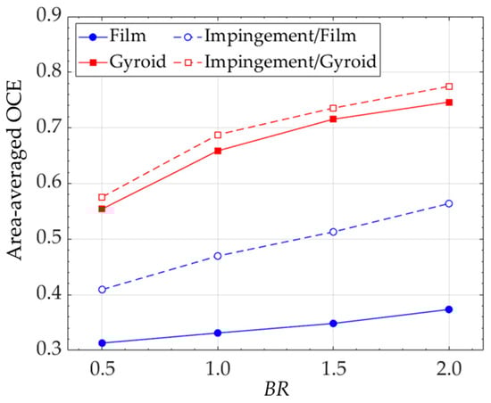
Figure 14.
Area-averaged overall cooling effectiveness on the hot-side surface of all models within the studied BR.
3.3. Total Pressure Loss and Performance Evaluation
The total pressure loss coefficient is plotted in Figure 15. In each design, the double-wall configuration causes a higher value than the single-wall one. For both single- and double-wall configurations, the Gyroid model causes higher values than the film hole model due mainly to the loss of hot gas flow, where the thick coolant is formed. At the BR of 2.0, the pressure loss coefficient for the Gyroid model is 0.29 and 0.31 in the single- and double-wall configurations, respectively. This represents an increase of 31.8% and 34.8% over the film hole model, which has values of 0.22 and 0.23 under the same conditions.
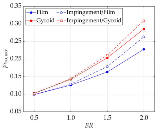
Figure 15.
Total pressure loss coefficient of all models within the studied BR.
The performance evaluation in this study is observed by plotting OCE against the total pressure loss coefficient, as shown in Figure 16. The jet impingement significantly influences the OCE for the film hole, especially at a higher BR. In addition, incorporating jet cooling has a low impact on the Gyroid model, which can be attributed to their high tortuosities and large hole areas that generate complex flow and significantly reduce the temperature in their pores. At an equal total pressure loss coefficient of 0.23 in all models, the film, impingement/film, Gyroid, and impingement/Gyroid models provide the area-average OCE value of 0.37, 0.54, 0.73, and 0.75, respectively. Therefore, the double-wall configuration with the Gyroid topology shows the best cooling performance in this study, demonstrating 102.7% superior cooling effectiveness than the conventional film hole.
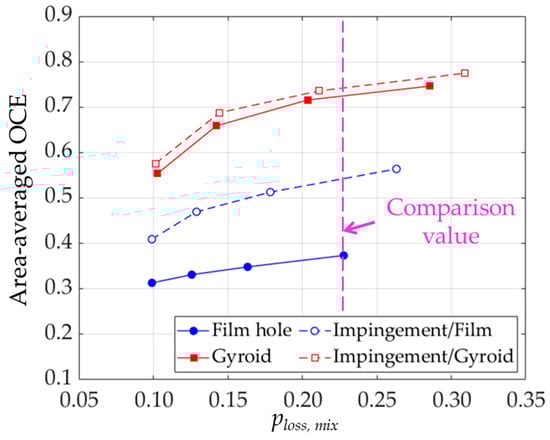
Figure 16.
Plot of the overall performance against the total pressure loss coefficient of all models within the studied BR.
3.4. Manufacturability Analysis
This section evaluates the manufacturability of an additively manufactured Gyroid effusion cooling model, scaled to match a gas turbine blade, as shown in Figure 17. The part is fabricated on a Renishaw AM250 laser powder bed fusion (LPBF) system using Inconel 718 powder with 15–53 μm particle sizes. The process parameters included a 200 W laser, an 80 μm beam diameter, and a 30 μm layer thickness. The printing direction is indicated in Figure 17a. After fabrication, the specimen is separated from the build platform via wire cutting.
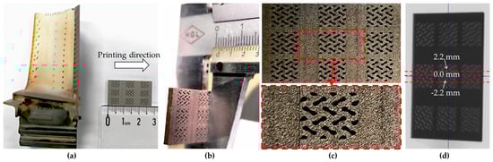
Figure 17.
Printed model: (a) Size comparisons with an aero-engine 1st stage rotor blade; (b) Measuring the thickness, (c) Enlarged view, and (d) Focused region in the high-resolution CT scanning.
The CAD model is designed with a 1.8 mm wall thickness to demonstrate printing capabilities, as seen in Figure 17b, and an enlarged view of the as-printed part is shown in Figure 17c. The resulting component is analyzed using high-resolution CT scanning, supported by the Instrumental Analysis Center at Shanghai Jiao Tong University. The analysis of the manufacturability features is presented, with critical regions highlighted in Figure 17d.
The internal structure of the printed samples is characterized using an Xradia 620 Versa micro-CT scanner, Carl Zeiss, Pleasanton, CA, USA. This system provides high-resolution 3D image quality, even at large working distances, enabling detailed analysis. Selected 2D cross-sectional images from the CT scans are presented in Figure 18.
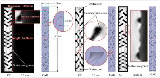
Figure 18.
High-resolution CT scan 2D results.
The CT analysis reveals manufacturability insights. The surface roughness is observed on the bottom surface of the printed specimen, attributed primarily to the stair-step effect inherent in layer-by-layer fabrication and the adhesion of partially sintered powder particles. This increased surface roughness, of either internal or external plate surfaces, enhances convective heat transfer, potentially improving cooling effectiveness; however, when placed on the internal holes, this roughness will significantly increase total pressure loss [21] and could reduce convective heat transfer, depending on the hole design [22].
Furthermore, geometric deviations from the CAD model are particularly evident at sharp edges. These inaccuracies result from the finite laser beam diameter of 80 µm, which rounds sharp corners [15,25]. This deviation alters the intended flow pathways and vortex generation points, which can modify local heat transfer coefficients and overall cooling uniformity. Most critically, internal channels also exhibit partial occlusions from residual unsintered powder, an issue most prevalent in regions with smaller cross-sectional areas, such as the tiny hole features, where powder removal is difficult. These occlusions constrict flow areas, leading to a maldistribution of coolant flow and increasing total pressure loss [21]. Moreover, this issue can create localized hot spots, degrading the overall cooling effectiveness.
Despite these defects, the overall structure exhibits minor warping, demonstrating the feasibility of the LPBF for manufacturing complex gas turbine blade geometries. While the quantitative impact of these defects on thermal performance could be significant, it is complex to model, representing a limitation of simulating designed geometries rather than as-built ones. This will be framed as an area for future work, utilizing CT-scanned geometries for more accurate simulation.
Process parameter optimization is one potential path to mitigate the specific defects observed in this study, such as surface roughness, internal occlusions, and geometric deviations [19]. Alternatively, a hybrid approach using AM-assisted investment casting presents a compelling solution. This method fabricates a sacrificial pattern via stereolithography (SLA), which is used to produce a ceramic mold for casting. The resulting metallic TPMS lattices exhibit smoother, cleaner surfaces and higher geometric precision, offering a more affordable route for fabricating complex cooling structures.
While LPBF provides superior mechanical properties due to its fine-grained microstructure from rapid solidification [17,18], the cooling performance is governed primarily by the geometry rather than these microstructural differences. Therefore, the minor microstructural differences between the AM-assist casting and LPBF specimens would have a minor impact, and the enhanced cooling performance enabled by the Gyroid design is preserved in the hybrid approach [18]. This approach could be preferable for hot-end components where geometric accuracy, surface finish, and cost-efficiency are prioritized alongside high cooling effectiveness.
4. Conclusions
In this study, Gyroid TPMS structures are proposed for high-performance effusion cooling designs. The conventional film hole model is used for comparisons. All models are also studied in the double-wall configuration by incorporating a jet impingement plate. The flow characteristics, pressure loss, and overall cooling effectiveness of single- and double-wall unit configurations are numerically investigated at blowing ratios (BRs) of 0.5 to 2.0. Moreover, the manufacturability of the printed Gyroid specimen is analyzed. The main findings can be concluded as follows:
(1) The Gyroid design prevents jet lift-off and eliminates counter-rotating vortex pairs for both single- and double-wall configurations. The discharged coolant in the Gyroid design fully covers the external plate and is much thicker than in the film hole model. Both single- and double-wall configurations with the Gyroid design enhance internal convective heat transfer due to their high surface-area-to-volume ratio. This results in greater in-hole cooling and the release of coolant at lower temperatures, ultimately leading to higher overall cooling effectiveness. Moreover, due to the complex topology of the Gyroid network, the temperature distribution on the external plate is more uniform than in the film hole.
(2) Due to additional jet impingement, the average Nusselt numbers in the double-wall configuration are much higher than those in the single-wall one, evident in the film hole model. The jet impingement in the Gyroid model has less influence on the temperature distribution on the external wall owing to its large surface area inside the plate. For the double-wall configuration, the area-averaged Nusselt number in the Gyroid design is superior to the film hole by 7.0–11.4% as the BR increases from 0.5 to 2.0.
(3) For all models, the overall cooling effectiveness and pressure loss increase as the BR increases. The Gyroid design shows higher overall cooling effectiveness than the film hole model for both single- and double-wall configurations. Incorporating jet impingement increases the cooling effectiveness and pressure loss. By evaluating all models at an equal total pressure loss, the impingement/Gyroid model shows the highest cooling effectiveness in this study, increased by 102.7% compared to the conventional film hole configurations.
(4) The Gyroid effusion model is additively manufactured via LPBF at the scale of a gas turbine blade. A high-resolution CT scan provides manufacturability insights for the LPBF-manufactured specimen. Defects such as surface roughness from stair-stepping and sintered powder adhesion, geometric deviations at sharp edges due to the laser diameter, and channel blockages from trapped powder are observed. Although these defects are present, the macro-scale geometric integrity of the structure is largely maintained, substantiating the feasibility of LPBF for fabricating complex cooling geometries for gas turbine blades.
Author Contributions
Conceptualization, K.Y. and Y.R.; methodology, K.Y. and Y.C.; software, K.Y., C.X. and Q.Z.; validation, K.Y., C.X. and Y.C.; formal analysis, K.Y. and Y.C.; investigation, C.X. and Q.Z.; resources, Y.R. and G.Z.; data curation, C.X., Y.C. and Q.Z.; writing—original draft preparation, K.Y.; writing—review and editing, K.Y., C.X., Y.R. and G.Z.; visualization, C.X., Y.C. and Q.Z.; supervision, Y.R.; project administration, Y.R.; funding acquisition, K.Y. and G.Z. All authors have read and agreed to the published version of the manuscript.
Funding
This work was supported by the National Natural Science Foundation of China (Nos. 11972230 and 24Z033103800), the National Science and Technology Major Project of China (No. 2017-III-0009-0035), and the Program for International Scientific Cooperation of the Science and Technology Commission of Shanghai Municipality (No. 24110712700).
Data Availability Statement
The original contributions presented in this study are included in the article. Further inquiries can be directed to the corresponding author.
Acknowledgments
The author, Yu Rao, gratefully acknowledges support from the Shandong Provincial Industrial Leading Talents Project.
Conflicts of Interest
Author Guodong Zhang was employed by the company Kangyue Technology Co., Ltd. The remaining authors declare that the research was conducted in the absence of any commercial or financial relationships that could be construed as a potential conflict of interest.
Nomenclature
| BR | Blowing ratio, defined in Equation (1) |
| Dj | Diamond of the jet hole (m) |
| Uc, Uh | Velocity of the coolant and hot gas (m/s) |
| Tc, Th | Temperature of the coolant and hot gas (K) |
| Tcw, Thw | Temperature of the cold-and hot-side walls of the external plate (m) |
| Nu | Nusselt number, defined in Equation (2) |
| q | Wall heat flux (W/m2) |
| kf | Thermal conductivity of the fluid (W/m·K) |
| ploss | Total pressure loss, defined in Equation (4) |
| , | Mass flow rate of the coolant and hot gas (kg/s) |
| pc,in, ph,in | Inlet pressure of the coolant and hot gas (Pa) |
| ph,out | Outlet pressure of the hot gas (Pa) |
| y+ | Dimensionless parameter to characterize the behavior of flow near a solid surface (-) |
| X, Y, Z | Cartesian coordinate (-) |
| Greek letter | |
| ρc, ρh | Density of the coolant and hot gas (kg/m3) |
| Abbreviations | |
| AM | Additive manufacturing |
| CRVP | counter-rotating vortex pair |
| OCE | Overall cooling effectiveness |
| IWP | I-graph, and wrapped package |
| TPMS | Triply periodic minimal surface |
| SLMS | Selective laser metal sintering |
Appendix A
Appendix A.1
Figure A1 shows the temperature-dependent properties of nickel-based superalloy, including thermal conductivity, heat capacity, Young’s modulus, and thermal expansion coefficient. The density and Poisson’s ratio are kept constant at values of 8344 kg/m3 and 0.3, respectively [44].

Figure A1.
Temperature-dependent properties of nickel-based superalloy.
Appendix A.2
The numerical model, boundary conditions, and mesh system for the impingement/effusion cooling analysis, designed to evaluate the overall cooling effectiveness and validate the numerical procedure of this study, are depicted in Figure A2. This model aligns with the IR experimental setup conducted by Jung et al. [49]. The boundary conditions, mesh configurations, and numerical setups for both the fluid and solid domains in this model are consistent with those used in the present study.

Figure A2.
Resemble numerical impingement/effusion cooling model for the validation of the computation procedure in this study: (a) Boundary condition and (b) Mesh system.
References
- Yeranee, K.; Rao, Y. A Review of Recent Studies on Rotating Internal Cooling for Gas Turbine Blades. Chin. J. Aeronaut. 2021, 34, 85–113. [Google Scholar] [CrossRef]
- Wang, W.; Yan, Y.; Zhou, Y.; Cui, J. Review of Advanced Effusive Cooling for Gas Turbine Blades. Energies 2022, 15, 8568. [Google Scholar] [CrossRef]
- Li, W.; Lu, X.; Li, X.; Ren, J.; Jiang, H. On Improving Full-Coverage Effusion Cooling Efficiency by Varying Cooling Arrangements and Wall Thickness in Double Wall Cooling Application. J. Heat Transf. 2019, 141, 042201. [Google Scholar] [CrossRef]
- Liu, Y.; Rao, Y.; Yang, L. Numerical Simulations of a Double-Wall Cooling with Internal Jet Impingement and External Hexagonal Arrangement of Film Cooling Holes. Int. J. Therm. Sci. 2020, 153, 106337. [Google Scholar] [CrossRef]
- Rao, Y.; Liu, Y.; Wan, C. Multiple-Jet Impingement Heat Transfer in Double-Wall Cooling Structures with Pin Fins and Effusion Holes. Int. J. Therm. Sci. 2018, 133, 106–119. [Google Scholar] [CrossRef]
- Mi, Q.; Yi, S.H.; Gang, D.D.; Lu, X.G.; Liu, X.L. Research Progress of Transpiration Cooling for Aircraft Thermal Protection. Appl. Therm. Eng. 2024, 236, 121360. [Google Scholar] [CrossRef]
- Kim, M.; Shin, D.H.; Lee, B.J.; Lee, J. Experimental and Numerical Investigation of Micro-Scale Effusion and Transpiration Air Cooling on Cascaded Turbine Blades. Case Stud. Therm. Eng. 2022, 32, 101892. [Google Scholar] [CrossRef]
- Cheng, Z.; Xu, R.; Jiang, P. Transpiration Cooling with Phase Change by Functionally Graded Porous Media. Int. J. Heat Mass Transf. 2023, 205, 123862. [Google Scholar] [CrossRef]
- Liu, Y.Q.; Jiang, P.X.; Xiong, Y.B.; Wang, Y.P. Experimental and Numerical Investigation of Transpiration Cooling for Sintered Porous Flat Plates. Appl. Therm. Eng. 2013, 50, 997–1007. [Google Scholar] [CrossRef]
- Xu, G.; Liu, Y.; Luo, X.; Ma, J.; Li, H. Experimental Investigation of Transpiration Cooling for Sintered Woven Wire Mesh Structures. Int. J. Heat Mass Transf. 2015, 91, 898–907. [Google Scholar] [CrossRef]
- Hinse, M.; Yildiz, K.; Richer, P.; Jodoin, B.; Bourmand, M.; Yun, S.; Hong, Z. Numerical and Experimental Studies of Transpiration Cooling Film Effectiveness over Porous Materials. J. Thermophys. Heat Transf. 2022, 36, 803–817. [Google Scholar] [CrossRef]
- Yeranee, K.; Rao, Y. A Review of Recent Investigations on Flow and Heat Transfer Enhancement in Cooling Channels Embedded with Triply Periodic Minimal Surfaces (TPMS). Energies 2022, 15, 8994. [Google Scholar] [CrossRef]
- Al-Ketan, O.; Abu Al-Rub, R.K. Multifunctional Mechanical Metamaterials Based on Triply Periodic Minimal Surface Lattices. Adv. Eng. Mater. 2019, 21, 1900524. [Google Scholar] [CrossRef]
- Wang, H.; Zhao, C.; Liu, W.; Liu, Z.; Bian, H.; Zhang, K. Advances in Triply Periodic Minimal Surface Structures for Thermal Management Systems: A Comprehensive Review. Appl. Therm. Eng. 2025, 279, 127481. [Google Scholar] [CrossRef]
- Min, Z.; Parbat, S.N.; Yang, L.; Chyu, M.K. Thermal-Fluid and Mechanical Investigations of Additively Manufactured Geometries for Transpiration Cooling. In Proceedings of the ASME Turbo Expo 2019: Turbomachinery Technical Conference and Exposition. Volume 5B: Heat Transfer, Phoenix, AZ, USA, 17 July–21 August 2019; American Society of Mechanical Engineers: New York, NY, USA; Volume 5B, pp. 1–13. [Google Scholar] [CrossRef]
- Der, O. Multi-Output Prediction and Optimization of CO2 Laser Cutting Quality in FFF-Printed ASA Thermoplastics Using Machine Learning Approaches. Polymers 2025, 17, 1910. [Google Scholar] [CrossRef]
- Qi, X.; Liang, X.; Wang, J.; Zhang, H.; Wang, X.; Liu, Z. Microstructure Tailoring in Laser Powder Bed Fusion (L-PBF): Strategies, Challenges, and Future Outlooks. J. Alloys Compd. 2024, 970, 172564. [Google Scholar] [CrossRef]
- Al-Ketan, O.; Singh, A.; Karathanasopoulos, N. Strut and Sheet Metal Lattices Produced via AM-Assisted Casting and Powder Bed Fusion: A Comparative Study. Addit. Manuf. Lett. 2023, 4, 100118. [Google Scholar] [CrossRef]
- Sadowski, M.; Ladani, L.; Brindley, W.; Romano, J. Optimizing Quality of Additively Manufactured Inconel 718 Using Powder Bed Laser Melting Process. Addit. Manuf. 2016, 11, 60–70. [Google Scholar] [CrossRef]
- Huang, G.; Min, Z.; Yang, L.; Jiang, P.-X.; Chyu, M. Transpiration Cooling for Additive Manufactured Porous Plates with Partition Walls. Int. J. Heat Mass Transf. 2018, 124, 1076–1087. [Google Scholar] [CrossRef]
- Stimpson, C.K.; Snyder, J.C.; Thole, K.A.; Mongillo, D. Roughness Effects on Flow and Heat Transfer for Additively Manufactured Channels. J. Turbomach. 2016, 138, 051008. [Google Scholar] [CrossRef]
- Snyder, J.C.; Thole, K.A. Performance of Public Film Cooling Geometries Produced through Additive Manufacturing. J. Turbomach. 2020, 142, 051009. [Google Scholar] [CrossRef]
- Kim, M.; Shin, D.H.; Kim, J.S.; Lee, B.J.; Lee, J. Experimental Investigation of Effusion and Transpiration Air Cooling for Single Turbine Blade. Appl. Therm. Eng. 2021, 182, 116156. [Google Scholar] [CrossRef]
- Xu, R.; Cheng, Z.; Jiang, P. Fundamentals and Recent Progress of Additive Manufacturing-Assisted Porous Materials on Transpiration Cooling. J. Glob. Power Propuls. Soc. 2023, 2023, 19–48. [Google Scholar] [CrossRef] [PubMed]
- Min, Z.; Huang, G.; Parbat, S.N.; Yang, L.; Chyu, M.K. Experimental Investigation on Additively Manufactured Transpiration and Film Cooling Structures. J. Turbomach. 2019, 141, 031009. [Google Scholar] [CrossRef]
- Huang, G.; Zhu, Y.; Liao, Z.-Y.; Huang, Z.; Jiang, P.-X. Transpiration Cooling with Bio-Inspired Structured Surfaces. Bioinspir. Biomim. 2020, 15, 036016. [Google Scholar] [CrossRef]
- Chyu, M.; Kang, B.; Parbat, S. Integrated Transpiration and Lattice Cooling Systems Developed by Additive Manufacturing with Oxide-Dispersion-Strengthened (ODS) Alloys; National Energy Technology Laboratory: Pittsburgh, PA, USA, 2022. [Google Scholar]
- Yeranee, K.; Rao, Y. A Review of Recent Research on Flow and Heat Transfer Analysis in Additively Manufactured Transpiration Cooling for Gas Turbines. Energies 2025, 18, 3282. [Google Scholar] [CrossRef]
- Şener, R.; Demir, M.E. Heat Transfer and Flow Characteristics of a Novel Turbulator Design in Heat Exchanger: Experimental and Numerical Analysis. Proc. Inst. Mech. Eng. Part A J. Power Energy 2024, 238, 1228–1237. [Google Scholar] [CrossRef]
- Yeranee, K.; Rao, Y. Turbulent Flow and Heat Transfer Enhancement for Turbine Blade Trailing Edge Cooling With Gyroid-Type Triply Periodic Minimal Surfaces. ASME J. Eng. Gas Turbines Power 2023, 145, 071008. [Google Scholar] [CrossRef]
- Yeranee, K.; Xu, C.; Rao, Y.; Chen, J.; Zhang, Y. Rotating Flow and Heat Transfer Characteristics of a Novel Cooling Channel for Gas Turbine Blade Trailing Edge With Diamond-Type TPMS Structures. ASME J. Heat Mass Transf. 2024, 146, 051002. [Google Scholar] [CrossRef]
- Yeranee, K.; Rao, Y.; Xu, C.; Zhang, Y.; Su, X. Turbulent Flow Heat Transfer and Thermal Stress Improvement of Gas Turbine Blade Trailing Edge Cooling with Diamond-Type TPMS Structure. Aerospace 2023, 11, 37. [Google Scholar] [CrossRef]
- Yeranee, K.; Xu, C.; Rao, Y.; Zhang, Y. Experimental and Numerical Study of Improving Flow and Heat Transfer in a Serpentine Cooling Channel with Topology-Optimized TPMS Porous Structures. Int. J. Heat Mass Transf. 2024, 231, 125873. [Google Scholar] [CrossRef]
- Gu, H.; Liang, D.; Duan, P.; Zhou, D.; Li, W. Aerothermal Characteristics of Thin Double-Wall Effusion Cooling Systems with Novel Slot Holes and Cellular Architectures for Gas Turbines. Aerosp. Sci. Technol. 2023, 1, 108441. [Google Scholar] [CrossRef]
- Yeranee, K.; Rao, Y.; Xu, C.; Xie, J.; Zhang, Y. Conjugate Heat Transfer and Fluid Flow Analysis on Printable Double-Wall Effusion Cooling with Internal Topology-Optimized TPMS Structures. Therm. Sci. Eng. Prog. 2024, 55, 102939. [Google Scholar] [CrossRef]
- Broumand, M.; Son, J.; Pyo, Y.; Yun, S.; Hong, Z. TPMS-Based Transpiration Cooling for Film Cooling Enhancement. Int. J. Heat Mass Transf. 2024, 231, 125824. [Google Scholar] [CrossRef]
- Son, J.; Broumand, M.; Pyo, Y.; Richer, P.; Jodoin, B.; Hong, Z. Effects of Lattice Orientation Angle on TPMS-Based Transpiration Cooling. In Proceedings of the Volume 13: Heat Transfer: General Interest/Additive Manufacturing Impacts on Heat Transfer; Wind Energy, London, UK, 24 June 2024; American Society of Mechanical Engineers: New York, NY, USA, 2024; Volume 13, pp. 1–13. [Google Scholar]
- Dutta, S.; Kaur, I.; Singh, P. Review of Film Cooling in Gas Turbines with an Emphasis on Additive Manufacturing-Based Design Evolutions. Energies 2022, 15, 6968. [Google Scholar] [CrossRef]
- Kim, K.M.; Song, J.; Park, J.S.; Lee, S.; Cho, H.H. Material Design of a Film Cooling System Using Experimental Heat Transfer Data. Int. J. Heat Mass Transf. 2012, 55, 6278–6284. [Google Scholar] [CrossRef]
- Kim, K.M.; Moon, H.; Park, J.S.; Cho, H.H. Optimal Design of Impinging Jets in an Impingement/Effusion Cooling System. Energy 2014, 66, 839–848. [Google Scholar] [CrossRef]
- Al-Ketan, O.; Abu Al-Rub, R.K. MSLattice: A Free Software for Generating Uniform and Graded Lattices Based on Triply Periodic Minimal Surfaces. Mater. Des. Process. Commun. 2021, 3, 1–10. [Google Scholar] [CrossRef]
- Nakamata, C.; Mimura, F.; Matsushita, M.; Yamane, T.; Fukuyama, Y.; Yoshida, T. Local Cooling Effectiveness Distribution of an Integrated Impingement and Pin Fin Cooling Configuration. Proc. ASME Turbo Expo 2007, 4, 23–34. [Google Scholar] [CrossRef]
- Li, H.; Xie, F.; Wang, Y.; Wang, C.; Yan, Y.; Cui, J. Numerical Investigation on the Cooling Effectiveness and Pressure Loss of a Novel Laminated Cooling Configuration With Cellular Partition. J. Therm. Sci. Eng. Appl. 2023, 15, 011015. [Google Scholar] [CrossRef]
- Cai, L.; He, Y.; Wang, S.; Li, Y.; Li, F. Thermal-Fluid-Solid Coupling Analysis on the Temperature and Thermal Stress Field of a Nickel-Base Superalloy Turbine Blade. Materials 2021, 14, 3315. [Google Scholar] [CrossRef] [PubMed]
- Ahn, J. Large Eddy Simulation of Film Cooling: A Review. Energies 2022, 15, 8876. [Google Scholar] [CrossRef]
- Liu, Y.; Rao, Y.; Yang, L.; Xu, Y.; Terzis, A. Flow and Heat Transfer Characteristics of Double-Wall Cooling with Multi-Row Short Film Cooling Hole Arrangements. Int. J. Therm. Sci. 2021, 165, 106878. [Google Scholar] [CrossRef]
- Li, H.; Li, L.; Li, Q.; Tang, Z.; Zhang, Z.; Chen, R. Coupling Characteristics and Simplification Analysis Method of Laminated Cooling Configuration between External and Internal Cooling. Int. J. Therm. Sci. 2023, 187, 108159. [Google Scholar] [CrossRef]
- Celik, I.B.; Ghia, U.; Roache, P.J.; Freitas, C.J.; Coleman, H.; Raad, P.E. Procedure for Estimation and Reporting of Uncertainty Due to Discretization in CFD Applications. ASME J. Fluids Eng. 2008, 130, 078001. [Google Scholar] [CrossRef]
- Jung, E.Y.; Chung, H.; Choi, S.M.; Woo, T.; Cho, H.H. Conjugate Heat Transfer on Full-Coverage Film Cooling with Array Jet Impingements with Various Biot Numbers. Exp. Therm. Fluid Sci. 2017, 83, 1–8. [Google Scholar] [CrossRef]
Disclaimer/Publisher’s Note: The statements, opinions and data contained in all publications are solely those of the individual author(s) and contributor(s) and not of MDPI and/or the editor(s). MDPI and/or the editor(s) disclaim responsibility for any injury to people or property resulting from any ideas, methods, instructions or products referred to in the content. |
© 2025 by the authors. Licensee MDPI, Basel, Switzerland. This article is an open access article distributed under the terms and conditions of the Creative Commons Attribution (CC BY) license (https://creativecommons.org/licenses/by/4.0/).