


Abstract
The integration of robotics into agriculture addresses challenges such as labour shortages and sustainable production. Handling delicate and irregular natural products remains difficult for conventional grippers. This paper presents a baromorphic end-effector as a proof-of-concept platform for validating a perception-sensing TCP realignment pipeline rather than as a field-ready agricultural product. The square-to-hexagonal layout choice was made iteratively through prototyping, whereas a finite-element analysis was used in prior work to optimise and characterise the hexagonal cushion unit. The materials, actuation, and robotic platforms serve as the experimental testbeds for the integrated control concept. The system uses a modular array of pneumatically actuated hexagonal cells with sparse embedded pressure sensing, vision-based object detection, a discrete heuristic visual servoing controller to bypass kinematic singularities during the approach, and a closed-loop TCP dynamic realignment algorithm. Under controlled laboratory conditions, the prototype achieved 12/12 successful linear grasps and 9/11 successful angular grasps (82%) on irregular produce, whereas a conventional rigid parallel-jaw gripper failed all attempted baseline trials under the same protocol.
1. Introduction
The agricultural sector faces increasing pressure to improve productivity while adopting more sustainable practices. This challenge is reinforced by population growth, projected to reach 9.7 billion by 2050 [1,2]; rising labour costs; and persistent workforce shortages [2]. Robotic automation offers a practical route to support labour-intensive operations such as harvesting [3]. However, manipulating delicate and irregularly shaped biological products without damage continues to be challenging for current robotic technologies.
Conventional grippers, including rigid devices or simplified soft actuators, often do not provide the necessary combination of compliance, adaptability, and sensory feedback [4]. Rigid grippers may apply excessive point pressure, which can damage soft produce [5]. Soft grippers, while compliant, frequently rely on global actuation and offer limited local adaptability, making it difficult to maintain stable or precise grasps in practice [6,7]. These limitations suggest that alternative gripper architectures with local deformation and real-time feedback could be beneficial.
Previous work by the authors [8] explored design and simulation principles for adaptive soft fingertips. Building on this starting point, the present study introduces the physical implementation and experimental evaluation of a sensor-integrated baromorphic end-effector. The term “baromorphic” denotes a structure whose deformation behaviour is governed by pressure-induced shape changes.
The system includes three main components. First, the gripper employs a modular architecture composed of hexagonal, pneumatically actuated cells capable of independent deformation. Second, a real-time TCP dynamic realignment algorithm adjusts the robot pose based on pressure sensor data during the grasp. Third, the system combines vision-based pre-positioning with tactile closed-loop correction. Comparative experiments demonstrate improved grasp reliability relative to commercial grippers. The approach is aligned with goals such as SDG 2 and SDG 12. This paper aims to demonstrate the feasibility of a perception-sensing TCP realignment pipeline for adaptive manipulation. The hardware configuration serves as a controlled experimental platform to validate the integrated control architecture, without claiming industrial optimisation or field-ready deployment.
Relative to our preliminary conference paper [9], the present manuscript extends that work by: (i) formalising the mathematical formulation of the pressure-driven TCP dynamic realignment control loop, building on the control-oriented development detailed in our later IROS study [10]; (ii) adding an experimental baseline against a commercial rigid parallel-jaw gripper under the same laboratory protocol; (iii) including quantitative theoretical references to the finite-element analysis of the hexagonal cushion unit, as documented in our prior design study [8]; (iv) providing a critical discussion of system limitations and sample size constraints in the reported experiments; and (v) introducing a formal, discrete heuristic reaching and convergent descent framework that bypasses traditional image Jacobian inversion, rendering the visual pre-positioning phase immune to kinematic singularities.
2. State-of-the-Art and Commercial Gripper Limitations
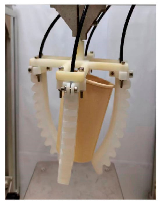
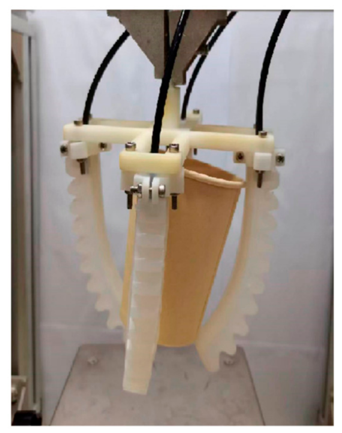
The field of robotic grasping encompasses a broad range of industrial technologies, extending from rigid mechanical devices used in manufacturing to compliant soft actuators intended for handling fragile items. Open-access pneumatic soft gripper prototypes, such as the flexible pneumatic gripper proposed by Lei et al. [11] and the tendon-driven variable-stiffness pneumatic gripper developed by Mawah et al. [12], provide royalty-free alternatives to proprietary industrial examples. These systems in Figure 1 and Figure 2 illustrate how compliant materials, pneumatic actuation, and adaptive deformation can support the grasping of fragile, irregular, or variable-geometry objects.
Figure 1.
Pneumatic soft gripper prototype. Reproduced from Lei et al. [11] under the Creative Commons Attribution License, CC BY 4.0.
Figure 2.
Tendon-driven variable-stiffness pneumatic soft gripper. Reproduced from Mawah et al. [12] under the Creative Commons Attribution License, CC BY 4.0.
Although these devices perform reliably in structured environments, especially if combined with expensive vision sensors, their limited surface conformity and the high local contact pressures generated at the gripping interfaces constrain their usefulness in agricultural contexts. Soft fruits and vegetables are prone to bruising or deformation, and rigid grippers generally lack integrated tactile sensing, making it difficult to detect excessive force or incipient slip during manipulation [13,14].
To address these limitations, soft robotic grippers have gained considerable attention. Companies, such as Festo and Soft Robotics Inc., have developed pneumatic elastomer-based grippers that can safely interact with delicate objects thanks to their inherent compliance. Academic research has also contributed significantly in this area, for example through granular jamming structures [15], fluid-driven soft actuators [16], and multi-material inflatable designs [6,7]. Despite these advances, many soft grippers rely on global actuation of entire fingers or chambers, which limits their ability to adapt locally to the fine geometrical variations typical of natural produce. Therefore, the pressure distribution often becomes uneven, grasp stability may be compromised, and buckling can occur when interacting with complex shapes. Sensory feedback, when integrated, is generally low resolution and unsuitable for fine control.
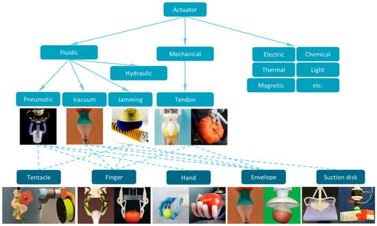
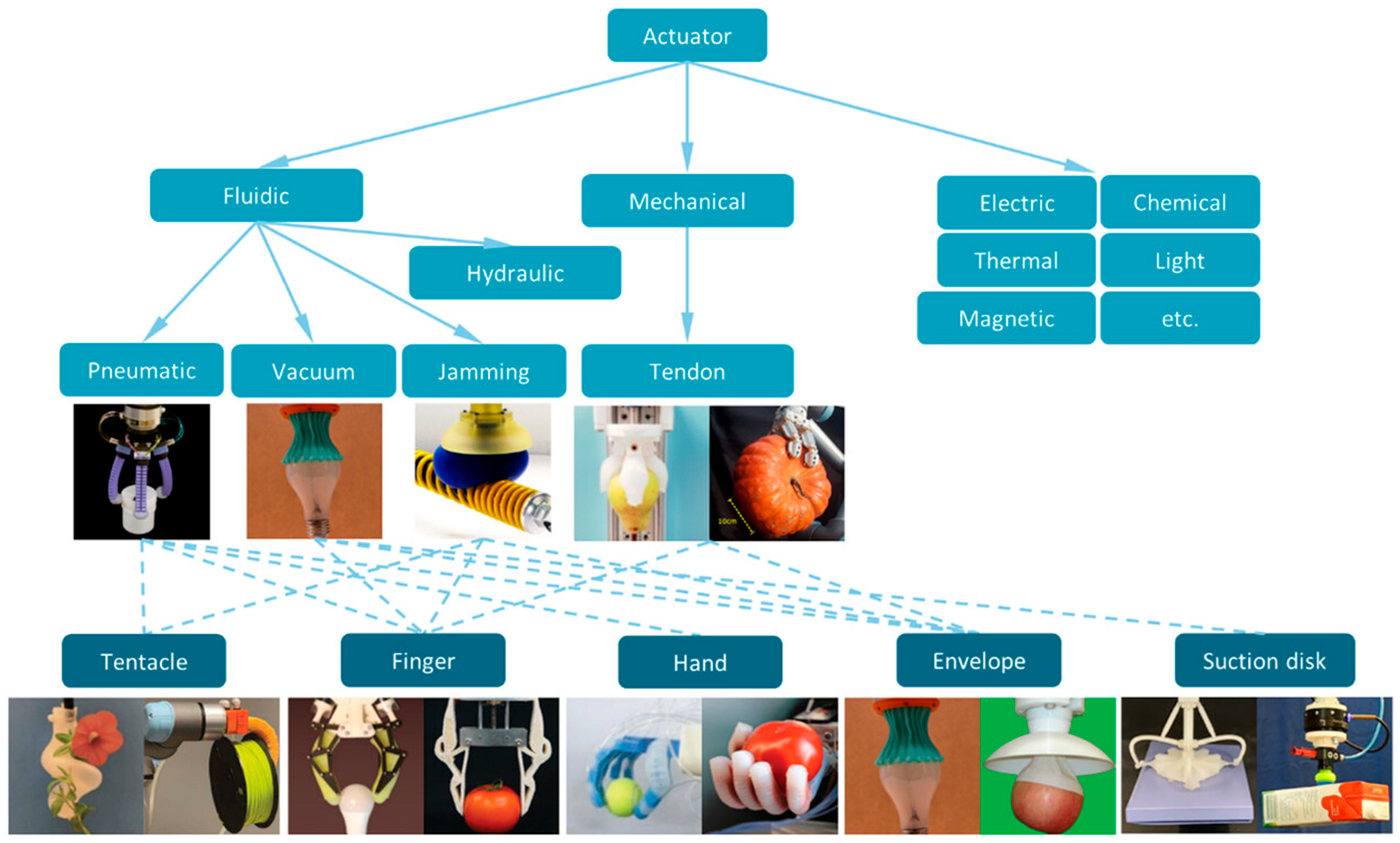
Hybrid and adaptive grippers attempt to bridge the gap between rigid precision and soft compliance. Examples include Robotics’ adaptive finger grippers, which can envelop objects of varying shape but remain limited in terms of localised deformation, as well as systems incorporating tactile sensor skins based on capacitive or piezoresistive arrays [17]. Other research directions involve variable-stiffness mechanisms, such as layer-jamming or phase-transition materials that can modulate compliance on demand [18]. Although these approaches offer promising capabilities, they frequently introduce additional wiring, power consumption, control complexity, and sensitivity to environmental conditions, all of which reduce their suitability for field applications in agriculture. As illustrated in Figure 3, various hybrid and adaptive gripping strategies have been proposed to overcome the limitations of purely rigid or purely soft actuation. Solutions range from pneumatic, vacuum, jamming and tendon-driven mechanisms to electric and material-based actuation, each mapped to different gripper morphologies, such as tentacles, fingers, envelopes, and suction systems. While these approaches demonstrate increasing versatility, current designs still face recurring issues, including limited local deformation control, added wiring and power requirements, and higher control complexity. As noted by Liu et al. [19], these constraints continue to hinder reliable deployment in agricultural environments.
Figure 3.
Examples of gripper types for agricultural applications, reprinted from ref. [19].
Taken together, these categories highlight the recurring limitations when applied to harvesting tasks. Rigid devices provide precision but insufficient compliance, soft grippers offer conformity but lack localised control and sensing, and hybrid solutions improve flexibility but often become complex and difficult to deploy. Across all these technologies, the fundamental challenge remains the same: achieving high-resolution local adaptability, real-time tactile feedback, and scalable modularity in a form factor capable of reliably handling irregular, delicate agricultural products. These limitations provide a rationale for exploring distributed, sensorised, pressure-driven gripping architectures, such as the baromorphic end-effector described in this work.
To quantitatively illustrate the performance gap, an evaluation matrix comparing the key requirements for agricultural grasping is presented in Table 1. This matrix synthesizes the common failures of commercial solutions observed during our preliminary studies and literature review, against which our proposed system is designed to perform.
Table 1.
Qualitative comparison of gripper design characteristics (not statistically benchmarked performance metrics). Footnote: The ratings (poor/moderate/good/excellent or low/high) are illustrative design judgments based on the literature and preliminary laboratory observations, not a blinded measurement protocol. For the proposed system, “Grasp Stability & Reliability” is set to good/excellent to reflect the laboratory success rates in Section 4 (12/12 linear; 9/11 angular), while other partial ratings acknowledge incomplete automation (manual pneumatics, sparse sensing).
3. System Architecture and Operational Principle
The proposed baromorphic end-effector is designed to test the perception-sensing TCP realignment pipeline described in this section and evaluated experimentally in Section 4. A schematic overview of the complete pipeline is provided in paragraph 3.3, illustrating the interaction between the vision module, the modular pneumatic cell array, the embedded pressure-sensing layer, and the TCP dynamic realignment logic. The baromorphic gripping system is structured as an integrated cyber–physical framework in which perception, actuation and control operate in continuous interaction to adapt the grasp to objects with irregular geometries. The overall mechanism relies on three interacting components: a vision module for preliminary object detection and initial pose estimation, a soft end-effector composed of a modular array of pressure-sensitive cells, and a control system that implements real-time Tool Centre Point (TCP) adjustments during the grasp.
3.1. A Modular Cellular Design for the Baromorphic End-Effector
The end-effector is based on a cellular structure composed of a tessellated array of hexagonal pneumatic units rather than a single monolithic soft body. This architecture allows the gripping surface to deform locally and independently at multiple points, enabling a degree of adaptability that conventional soft grippers with global actuation cannot achieve. The choice between square and hexagonal cells was made iteratively through prototype trials and geometric reasoning, not through a simulated square-versus-hexagonal FEM benchmark. Once the hexagonal layout was selected, a finite-element analysis was applied to optimise and characterise the hexagonal cushion unit; the quantitative simulation outputs are reported in our prior component-level study [8]. Beyond its mechanical adaptability, the hexagonal topology was also selected for its geometric versatility, since it can be systematically extended or reconfigured into alternative morphologies, for example by combining hexagons with pentagons or by generating gently curved surfaces while maintaining manufacturability and uniform pneumatic behaviours. This provides a scalable design space suitable for tailoring the end-effector to different crop geometries and operational scenarios. The prototype end-effector consists of a modular array of hexagonal pneumatic cells arranged within a compact circular frame. Each cell has a face-to-face width of approximately 30 mm; the overall array outer diameter is approximately 95 mm. The grasping envelope is defined by pneumatic cell expansion and by the robot workspace; in the reported experiments, positional offsets of up to ±170 mm and a pre-grasp Z-clearance of 50 mm were tested. These dimensions help validate the geometric adaptability concept rather than representing a finalised agricultural deployment configuration.
The early development focused on square-cell units because of their simplicity and ease of fabrication. The iterative prototype trials and geometric reasoning revealed drawbacks of this layout: negligible deformation near the corners (mechanical dead zones), high strain concentrations under inflation, and anisotropic expansion depending on the loading direction. These observations are reported here qualitatively because square cells were not subjected to a dedicated FEM campaign in this work. The move away from square geometry was therefore an iterative design decision rather than the outcome of a numerical square-versus-hexagonal comparison.
The transition to a hexagonal geometry mitigated the issues observed with the square prototypes. Hexagonal cells deform more uniformly in practice, tessellate without the gaps typical of square packing, and provide a more continuous contact surface for irregular produce. A finite-element analysis was then applied to optimise the hexagonal cushion design. In our prior design study [8], the hexagonal unit was modelled as silicone rubber (Young’s modulus E = 3 MPa; Poisson’s ratio ν = 0.49) and analysed under staged inflation of up to 1.00 bar, yielding a maximum displacement of 7.86 mm; the full input parameters, pressure–displacement response, and von Mises stress distributions are reported in Table 1 and Figure 3, Figure 4 and Figure 5 in [8]. The present manuscript summarises these quantitative outputs rather than reprinting the complete simulation campaign. Because square cells were not simulated, no numerical square-versus-hexagonal FEM benchmark is claimed here; the geometry selection remained iterative, whereas the FEM supported optimisation of the adopted hexagonal unit.
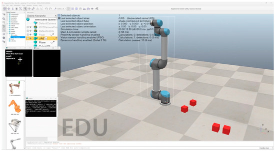
Figure 4.
Proposed heuristic reaching simulation in CoppeliaSim—starting point.
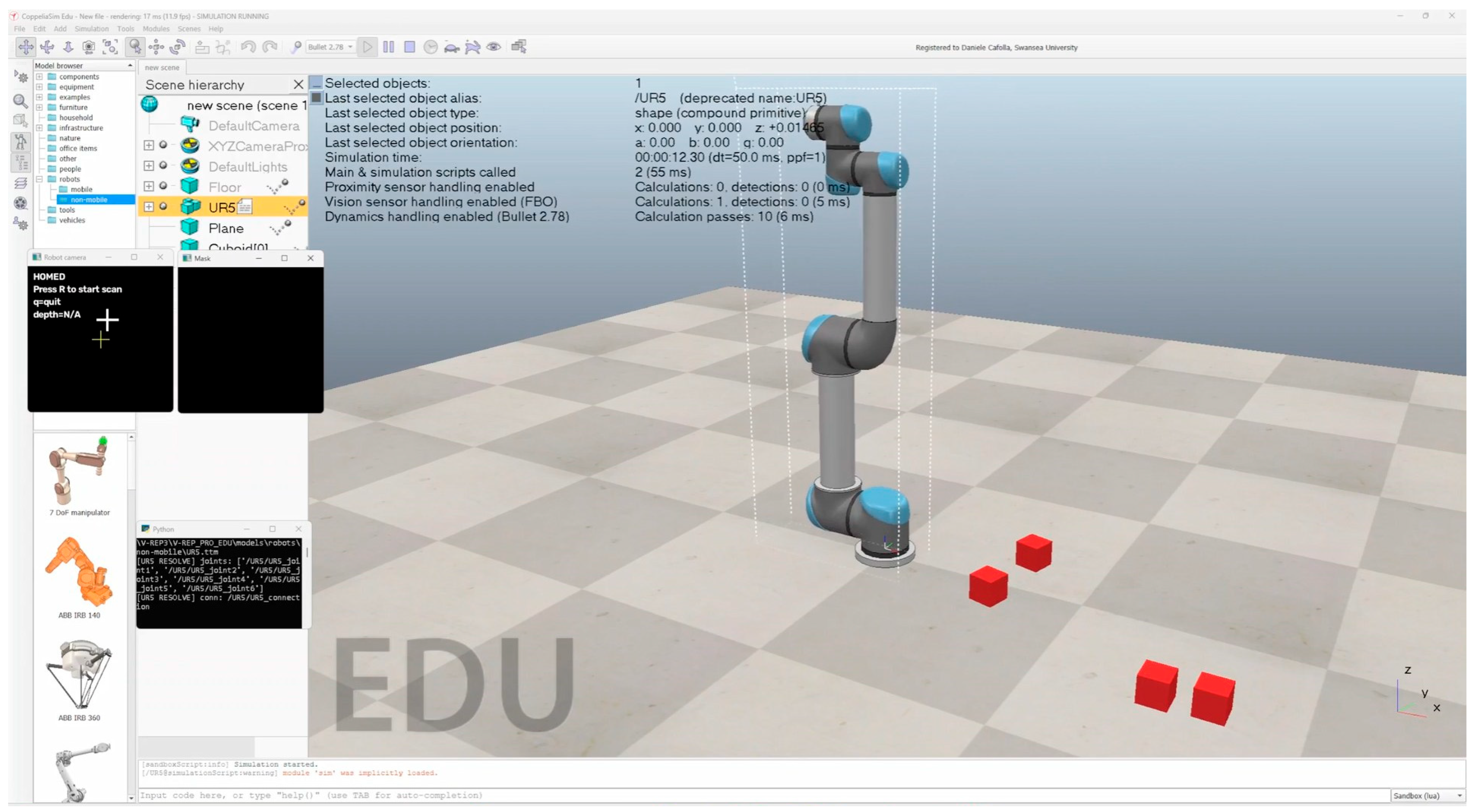
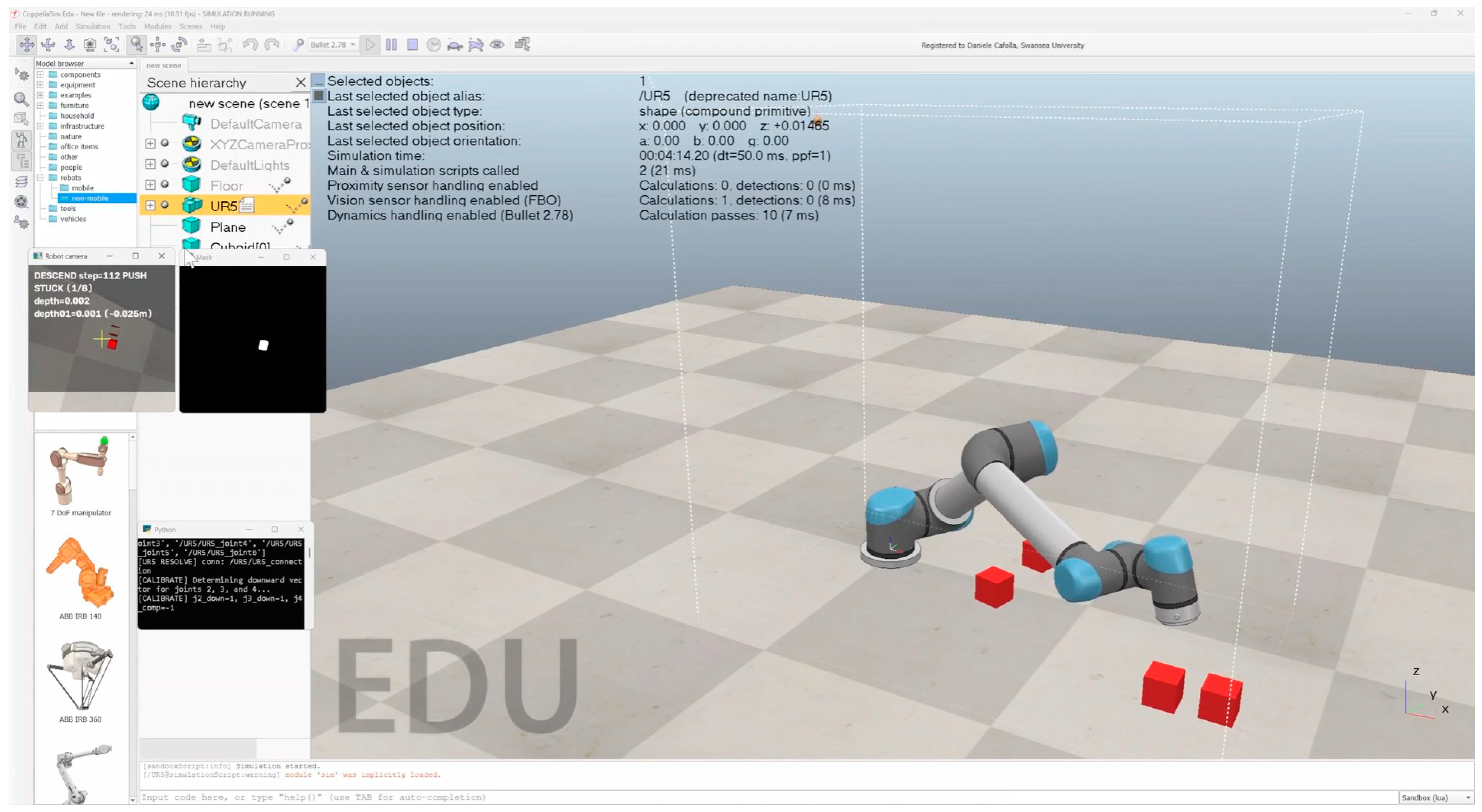
Figure 5.
Proposed heuristic reaching simulation in CoppeliaSim—final point.
The prototype cells were manufactured using SLA additive fabrication with flexible photopolymer resins, such as Formlabs 80A. SLA was selected for the initial phase because it provides high geometric resolution, smooth surfaces and precise reproduction of the internal pneumatic channels required for validation of the deformation behaviour predicted by the FEM. This level of accuracy was essential for integrating embedded pressure sensors and for characterising the mechanical response of the cellular structure under controlled laboratory conditions. Each cell functions as an independent pneumatic actuator whose localised deformation can be inferred from the internal pressure measurements, enabling real-time correction of the Tool Centre Point during a grasp.
Despite these advantages, the reliance on SLA fabrication introduced several limitations that prevent it from being a viable long-term solution for field-ready agricultural robotics. SLA photopolymers exhibit time-dependent creep, sensitivity to environmental conditions and progressive material fatigue under cyclic actuation, all of which reduce their durability compared to thermoplastic elastomers or silicone-based materials. Their tear resistance and elongation at break are insufficient for the repeated, high-strain cycles typical of pneumatic soft robotics. The fabrication process itself imposes constraints on the minimum dimensions of internal channels, which must remain sufficiently large to allow resin drainage, limiting the degree of miniaturisation achievable for more advanced sensor layouts or multi-chamber designs. Moreover, the flexural properties of SLA resins degrade with UV exposure and temperature fluctuations, conditions that are common outside controlled laboratory environments.
For these reasons, the SLA-based prototypes served primarily as validation tools for the geometric and control principles rather than as final components for deployment. Future iterations of the end-effector will require materials with enhanced mechanical resilience, such as thermoplastic polyurethane produced through fused-filament fabrication or silicone elastomers manufactured through casting and soft-lithography techniques. These materials offer superior fatigue resistance, greater elongation capabilities, and more stable performance under repeated deformation, making them better suited for the continuous operation expected in agricultural applications.
3.2. Vision Processing and Heuristic Reaching
The grasping sequence begins with the perception component of the system, which provides an initial estimate of the object’s position before any physical interaction occurs. A camera rigidly mounted on the robot’s arm captures an image of the workspace from a known perspective, ensuring that the subsequent interpretation of the visual data can be consistently mapped onto the robot’s coordinate frame. The acquired image is processed using a standard, off-the-shelf pre-trained YOLOv11 object detection model [20] (e.g., trained on a general-purpose dataset, such as COCO), used strictly to provide a coarse initial bounding-box region of interest for the subsequent tactile stage. No crop-specific custom dataset was trained for this study; consequently, the dataset size, class splits and mAP metrics are outside the scope of this hardware- and control-focused proof-of-concept (see also the conference pipeline description in [9]).
Once the bounding box is obtained, it defines a region of interest (ROI). Within this ROI, a binary mask is generated by thresholding, and the geometric centroid (cX, cY) is computed from the mask contour through image spatial moments (Equations (1) and (2)). The centroid is therefore derived from the segmented silhouette inside the ROI, not from the rectangular bounding-box corners alone. This descriptor is then transformed into the robot’s operational space through a camera-to-robot calibration procedure. Although the centroid does not provide complete information about the object’s orientation or three-dimensional geometry, it offers a robust and computationally efficient estimate of where contact is likely to occur.
This visually derived pose estimation is then used to generate a pre-grasp configuration. The robot positions its Tool Centre Point (TCP) at a location directly above the estimated centroid while maintaining a predefined clearance along the vertical axis. This positioning ensures that the initial approach is guided by perception rather than blind motion, reducing the likelihood of collisions and limiting the need for excessive exploratory movements during the first phase of the grasp. The alignment of the TCP with the detected centroid also establishes a suitable starting point for the subsequent tactile refinement process; as the end-effector descends and begins to interact with the object, embedded pressure sensors provide real-time information that is used to correct the residual errors inherent in vision-based localisation.
Depth variation is handled through the manipulator vertical axis: after planar alignment, the Niryo NED2 arm descends from a predefined clearance (50 mm above the support plane in the reported experiments) until contact is sensed. No mobile crawler base is used. Equations (1) and (2) describe planar centroid estimation; the approach in depth is achieved through the predefined Z-motion and subsequent contact-driven TCP dynamic realignment (planar vision localisation with limited contact-driven translation), not full six-degree-of-freedom pose estimation.
In this way, the vision module does not attempt to achieve perfect accuracy, but instead furnishes a reliable coarse estimation that places the gripper within the operational envelope required for tactile feedback to take over. The interaction between vision-based pre-positioning and sensor-driven correction forms a sequential perception and action pipeline in which the visual information initiates the task, and tactile sensing ensures the precision necessary for the stable and damage-free grasping of irregular agricultural products. The (cX, cY) of this bounding box are calculated using spatial moments (Equations (1) and (2)), providing an initial estimate of the object’s position in the robot’s coordinate frame.
The initial phase of the grasping pipeline identifies the target object and performs a singularity-free visual approach. The RGB-D vision sensor, mounted in an eye-in-hand configuration, acquires an RGB image with RGB dimensions and a normalised depth map. Following object detection via a pre-trained YOLOv11 model, target isolation is performed in the HSV colour space using binary thresholding to generate a mask. The spatial moments of the largest valid contour in the mask are computed as in (3):
where
- represents the raw spatial image moment of order p and q.
- represents the binary image mask bounding the segmented target object.
- and represent the horizontal and vertical pixel coordinates within the image plane.
- represents the pixel intensity value at coordinates x, y (yielding 1 for the object contour and 0 for the background).
The pixel coordinate centroid of the target (, ) is extracted using the zeroth- and first-order moments, as in Equation (2).
To achieve scale invariance across varying camera resolutions and distances, the pixel coordinates are mapped, as in Equations (4) and (5), into a normalised error space relative to the camera’s optical centre:
where
- and represent the calculated horizontal and vertical image plane centroid coordinates (in pixels).
- and represent the normalised horizontal and vertical alignment errors, bounded within [−0.5, 0.5].
- and represent the absolute width and height of the camera’s image plane resolution (e.g., ).
The total centring scalar error E is defined as the Euclidean distance from the optical centre, as in Equation (6):
where
- represents the total scalar centring error used to evaluate the target alignment.
Concurrently, a localised median filter is applied around the centroid within the depth map to reject noise and extract a robust normalised depth measurement as in Equation (7):
where
- represents the scalar normalised depth value returned by the vision sensor, bounded within [0, 1].
- represents the raw two-dimensional depth map matrix.
- represents the radius of the pixel sampling window used for the median filter (e.g., 7 pixels).
Given the vision sensor’s near, , and far, , clipping planes, the metric spatial distance to the target is approximated as in Equation (8):
where
- represents the estimated absolute metric distance to the target along the camera’s optical Z-axis (in meters).
- and represent the near and far clipping plane distances of the simulated vision sensor (e.g., 0.01 m and 10.0 m, respectively).
Traditional Image-Based Visual Servoing (IBVS) relies on the pseudo-inverse of the image Jacobian to map these 2D features to 3D joint velocities. However, this matrix inversion is prone to severe instability near kinematic singularities, such as a straight-arm configuration. To bypass this, we formulate the reaching phase as a discrete, heuristic search directly in the joint space in .
A discrete action space consisting of predefined joint step vectors is defined. At each iteration, the system samples candidate moves based on the current configuration (9):
where
- represents the proposed n-dimensional joint configuration vector.
- represents the manipulator’s current joint configuration vector.
- represents a discrete joint step vector drawn from a predefined action dictionary.
A cost function evaluates each candidate, incorporating both the centring error and the target pixel area, , to differentiate between local minima as in Equation (10):
where
- represents the scalar cost (fitness score) of the proposed movement.
- represents the weighting coefficient that penalises off-centre alignment.
- represents the weighting coefficient that rewards moving closer to the object (increasing its apparent size).
- represents the predicted apparent pixel area of the target at the proposed configuration (equivalent to ).
- represents a normalisation constant denoting the maximum expected pixel area.
The manipulator’s configuration is updated greedily following Equation (11) by selecting the candidate move that maximises this cost function until the centring error falls below an acceptable tolerance, :
where
- represents the optimally selected joint configuration for the subsequent physical time step.
Once the target is successfully centred in the field of view, the system must descend along the camera’s optical axis. Attempting to descend while simultaneously correcting cantering errors is a highly coupled problem that often induces control oscillation. We resolve this by decoupling the descent into a discrete switched-system controller governed by two mutually exclusive states: Centre Mode and Push Mode.
At each time step, the system evaluates the centring error against a relaxed descent threshold. If the error exceeds this threshold, the descent is paused, and the system enters Centre Mode. A local search is invoked using only the base and wrist yaw joints—which minimally impact the vertical height—to drive the error back toward zero. If the centring step is too large and overshoots the target, an exponential decay factor shrinks the step size to guarantee stable convergence, as in Equation (12):
where
- represents the angular step size amplitude used for lateral centring adjustments.
- represents the exponential decay factor (where ) applied during an overshoot event.
If the error is within the limits, the target is deemed safely centred, and the system enters Push Mode. The algorithm commands a physical descent along a previously calibrated downward vector. The step multiplier scales proportionally with the current distance, allowing for rapid traversal at a distance and highly precise micro-adjustments near the target surface, as in Equation (13):
where
- represents a dynamic scalar step multiplier that is a proportional function of the current metric depth .
- represents the empirically calibrated joint vector that produces pure Cartesian downward motion in the camera’s local frame.
To test the feasibility of our algorithm, a simulation was performed using CoppeliaSim software (V4.9.0 rev6) and UR5 Specific Kinematic Mapping. For the Universal Robots UR5 manipulator, the downward push relies primarily on the shoulder lift and elbow joints. However, actuating these joints inherently tilts the wrist, driving the target out of the camera’s view. To achieve a pseudo-linear Cartesian descent purely in joint space without requiring an Inverse Kinematics solver, a strict geometric compensation heuristic was applied to the wrist joint to lock the camera’s pitch relative to the world frame, as in Equation (14):
where
- represents the angular displacement applied to the wrist joint.
- represents the angular displacement applied to the shoulder lift joint.
- represents the angular displacement applied to the elbow joint.
During Push Mode, the resulting full-matrix step update translates to Equation (15):
During Centre Mode, compensation is isolated to the base and wrist rotation as in Equation (16), leaving the vertical height actuators untouched:
where
- and represent the updated 6-DOF joint vectors for the respective active modes.
- and represent the adaptive step multipliers (equivalent to ) for depth pushing and lateral centering.
- represents the angular displacement of the base joint.
- represents the angular displacement applied to the wrist joint.
Standard industrial grasping relies on integrated six-axis force–torque sensors to detect surface contact. We propose a sensorless visual-kinematic alternative. If a downward push is commanded, but the visual depth fails to decrease by a minimum tolerance delta for multiple consecutive iterations, a physical bottoming-out against the object is inferred. This condition safely halts the descent phase and triggers the final grasping sequence, as in Equation (17):
where
- represents the temporal change in the normalised visual depth between consecutive control iterations.
Figure 4 and Figure 5 show a simulation scenario where a UR5 was used in the CoppeliaSim environment with a randomly generated cube simulating the fruit. The robot was able to scan detect the most approachable one, centre it, and descend up to the grasping point with an and , reaching a height of 2.5 cm. The figures show the camera of the robot and the seen mask.
To rigorously evaluate the performance of the vision-based grasping policy, an automated testing framework is developed within the CoppeliaSim environment. The experiment consists of multiple independent, consecutive trials. In each trial, a varying number of spherical target objects are spawned at randomised coordinates upon the workspace table. The robot executes a fully autonomous sequence comprising a homing phase, a rotational scanning phase to locate the optimal target, a planar reaching phase to centre the target in the field of view, and a convergent descent phase governed by proportional depth control.
A trial is classified as a success (evaluated as a Boolean True) if the descent algorithm satisfies its termination condition without exceeding the maximum allowable iteration limits or permanently losing visual tracking of the target. Specifically, the descent loop terminates successfully under two conditions:
The normalised depth value sampled at the object centroid drops below the predefined target threshold. If the estimated depth indicates the end-effector is extremely close to the table ), and the proportional controller attempts to execute downward push movements but fails to decrease the depth further for 8 consecutive iterations, the system assumes physical contact has been achieved.
Upon successfully satisfying either of these conditions, the trial is logged as a success, and the script records the final positioning and visual metrics. If the robot loses sight of the target for more than the allowable frame limit or exceeds the maximum step count without reaching the table, the trial is aborted, marked as a failure (False), and the robot resets to the home position for the subsequent trial.
In each experimental trial, the simulation dynamically generates a randomised environment to test the robustness of the grasping policy. Between 3 and 6 cubic objects, representing the target fruits, are procedurally spawned on the workspace table. Each fruit is modelled as a dynamically respondable, collidable primitive cube with a uniform physical radius m.
To facilitate colour-based visual segmentation by the camera, the objects are assigned a distinct red, diffuse colour profile. The initial spatial coordinates of the fruits are uniformly randomised within a bounded planar workspace along the table’s surface to ensure varied and unpredictable approach trajectories for the robotic manipulator.
Once spawned, the algorithm calculates the radial distance of each fruit relative to the robot’s base frame. The specific target fruit for the trial is autonomously selected by filtering for objects within the kinematically reachable workspace (between 0.25 m and 0.55 m).
To quantify the accuracy and consistency of the grasping policy across all successful trials, multiple error metrics are logged at the exact moment the success condition is triggered. These metrics evaluate both the physical kinematic accuracy of the robot and the perceptual accuracy of the vision system. A trial is marked as a success (True) if the robot successfully completes the descent phase by either reaching the precise depth target threshold ); stagnating very close to the target for 8 consecutive frames or by detecting a hard physical collision after making zero downward progress for 25 consecutive frames.
The physical grasping error is the primary metric for physical accuracy and is the 3D Euclidean distance between the robot’s Tool Centre Point (TCP) and the actual centre of the target object. This metric relies on the absolute ground-truth coordinates extracted directly from the physics engine and is the absolute coordinates of the target object’s centre. The physical error is calculated as in Equation (18):
The visual alignment errors () are used to evaluate the performance of the visual servoing alignment prior to the grasp; the planar visual tracking errors are calculated. These errors represent the normalised deviation of the target’s visual centroid from the camera’s optical centre. Let W and H represent the width and height of the camera’s resolution, and represent the pixel coordinates computed as in Equations (4) and (5).
The depth estimation error () is computed because the descent policy relies on the visual depth data, so it is critical to measure the discrepancy between the depth sensor’s estimation and the actual physical distance to the object. The estimated depth () is derived from the vision sensor’s normalised depth buffer .
The real depth () is the absolute ground-truth distance from the camera’s origin to the top surface of the target object. This is calculated by querying the Z-axis distance of the object relative to the camera’s local coordinate frame (), and subtracting the known physical radius of the sphere inscribed in the cubic object, as in Equation (19):
Finally, the absolute depth sensor error is therefore the absolute difference between the estimated and real values using Equation (20):
To assess the overall reliability of the system, the mean and standard deviation are calculated for each error metric across all 100 successful trials. The mean provides the expected accuracy of the system, while the standard deviation serves as a measure of precision and repeatability.
The following section presents the quantitative results obtained from the experimental trials. The performance of the system is evaluated based on the overall success rate and the statistical distribution of the aforementioned error metrics across all successful grasping attempts. These aggregated metrics highlight the robustness of the proposed control policy, the precision of the visual servoing alignment, and the limitations of the depth estimation framework under dynamic simulation conditions.
In addition to the grasp-success tests reported in [9], we conducted a separate virtual benchmark focused exclusively on the autonomous approach, terminal descent, and centring accuracy prior to contact. The autonomous visual servoing and grasping pipeline was evaluated over a series of trials to assess its reliability and precision following the introduced procedure. The system demonstrated a robust 85% overall success rate (85 successful grasps out of 100 trials) in dynamically detecting, approaching, and descending upon the stochastically placed targets. The alignment precision during the terminal descent phase was highly consistent, yielding a mean absolute centring error of 0.0941 (±0.0972) on the X-axis and 0.1522 (±0.1308) on the Y-axis in normalised image coordinates. Furthermore, the vision-based depth estimation proved highly accurate when compared to ground-truth physical distance; the system’s estimated target depth averaged 0.1100 m (±0.1623 m) against a real physical depth of 0.1029 m (±0.1395 m). This resulted in an average depth perception error of merely 0.0552 m (±0.0729 m). Finally, the terminal 3D Euclidean error between the Tool Centre Point (TCP) and the object centroid averaged 0.5390 m (±0.1897 m), largely reflecting the engineered safety offsets and volumetric constraints of the simulated end-effector geometry. Overall, the data confirms the efficacy of the proportional depth controller and adaptive step sizing in overcoming kinematic lockup and local minima during autonomous descent.
3.3. The Role of Real-Time TCP Dynamic Realignment
The introduced vision-derived pose estimate is used to guide the robot to a pre-grasp position, aligning the Tool Centre Point (TCP) approximately with the object’s centroid. A central feature of the proposed system is its capacity to adjust the Tool Centre Point (TCP) dynamically during the grasp rather than relying on a fixed pose defined before contact. Conventional robotic manipulation assumes that the TCP is accurately positioned prior to interaction, an assumption that holds in structured industrial settings but becomes problematic when dealing with agricultural products. Natural produce exhibits variability in shape, size, curvature and orientation, making perfect pre-positioning difficult to guarantee. As a result, grasp attempts based solely on vision often lead to unstable contact, ineffective force distribution or unintended damage.
The present system addresses these limitations through continuous feedback from two instrumented pressure sensors embedded in diametrically opposed cells of the baromorphic array. During contact, the sensors provide a bilateral pressure estimate sufficient to detect left–right imbalance. The control law uses the signed difference ΔP = PR − PL as a one-dimensional asymmetry indicator; it does not reconstruct a full pressure field over the array. Any imbalance indicates that the TCP is not aligned with the object’s centre of geometry. Instead of treating such deviations as failure cases, the control algorithm interprets them as informative cues that guide incremental adjustments to the robot pose during contact.
To ensure the visual control architecture remains entirely agnostic to the specific end-effector geometry (such as the pneumatic baromorphic gripper utilised in this study), the framework dynamically maps the terminal frame of the kinematic chain upon initialisation, tested in CoppeliaSim, as a feasibility study.
The algorithm programmatically traverses the scene graph to identify the deepest attached physical link. It then instantiates a virtual Tool Centre Point (TCP) frame attached to this terminal link. The forward kinematics to this TCP is mathematically defined as in Equation (21):
where
- represents the final homogeneous transformation matrix defining the pose of the TCP relative to the robot’s absolute base frame .
- represents the total number of joints/links in the manipulator’s kinematic chain.
- represents the transformation matrix from frame i − 1 to frame i as a function of the respective joint angle .
- represents the static transformation offset from the terminal physical link to the virtual TCP.
This mathematical abstraction serves as the crucial bridge between the visual servoing phase and the tactile phase. The convergent descent algorithms guide the optical centre toward the target, and upon implicit contact detection, the physical grasping logic engages relative to the dynamically generated frame, entirely decoupling the vision logic from the hardware dimensions.
Once the first contact is established, the asymmetry detected in the pressure signals becomes immediately informative. During this phase, the system performs lateral and vertical shifts of the TCP to redistribute the forces more uniformly across the active cells, thereby improving the centring of the object within the gripping structure. As the grasp becomes more established and the pneumatic pressure stabilises, a final refinement stage corrects any residual misalignment caused by local compliance of both the end-effector and the object. This ensures that the load is shared evenly across the contact surface, minimising the risk of slippage, excessive localised pressure or deformation of delicate produce.
The realignment is governed by a proportional control law mapped to the relevant translational axis of the robot arm. The required displacement of the Tool Centre Point () is calculated as in Equation (22):
where is the proportional gain defining the mm/kPa responsiveness of the system, and ΔP is the calculated pressure difference ( − ). The numerical procedure governing this closed-loop routine is defined in Algorithm 1.
| Algorithm 1: TCP Dynamic Realignment Routine |
| Input: P_L (Left pressure), P_R (Right pressure), K_p (Proportional gain), (Th) Threshold |
| Output: Updated TCP Position (X_new) |
| 1: Initialise vertical grasp approach |
| 2: WHILE grasp is incomplete DO |
| 3: Read P_L, P_R from embedded sensors |
| 4: Calculate ΔP = P_R − P_L |
| 5: IF |ΔP| > Th THEN |
| 6: Calculate displacement: ΔTCP_pos = K_p · ΔP |
| 7: Update TCP coordinate: X_new = X_current + ΔTCP_pos |
| 8: Command robot to move to X_new |
| 9: ELSE |
| 10: Grasp is centred; continue vertical approach |
| 11: Inflate retaining cells and BREAK |
| 12: END IF |
| 13: END WHILE |
A profound scientific and practical advantage of this specific discrete control architecture is its native mathematical compatibility with modern Artificial Intelligence ecosystems, specifically Deep Reinforcement Learning (DRL) standards such as AI Gymnasium.
Standard continuous Image-Based Visual Servoing is analytically rigid and highly sensitive to hyperparameter tuning, making it a poor fit for discrete DRL action spaces. Conversely, the heuristic script developed in this framework is structurally formulated as a formal Decision Process (DP).
Within the context of a Reinforcement Learning paradigm, our framework maps perfectly to the required inputs and outputs of a neural network agent:
- The State Space : The normalised centring errors (), the filtered depth metric (), and the current joint positions () fully define the observable state array at time .
- The Action Space (): The predefined, discrete joint step increments () map natively to a standard discrete or multi-discrete AI action space, preventing the agent from requesting physically impossible or unbounded velocity commands.
- The Reward Signal (): The explicitly defined heuristic cost function serves directly as a highly shaped, dense reward signal, providing the agent with immediate numerical feedback regarding the centring precision and target proximity on every step.
Because of this rigid structural alignment, this heuristic controller acts as a standalone visual servoing tool, and as an “Expert Policy.” In future work, this discrete framework will be deployed as a Gymnasium environment wrapper. This will allow us to autonomously generate millions of successful, singularity-free grasping trajectories. These expert trajectories will subsequently be leveraged to train highly robust, vision-based DRL agents via Imitation Learning and Behavioural Cloning, effectively circumventing the severe sample inefficiency and exploration bottlenecks that currently limit end-to-end neural network approaches in robotic manipulation.
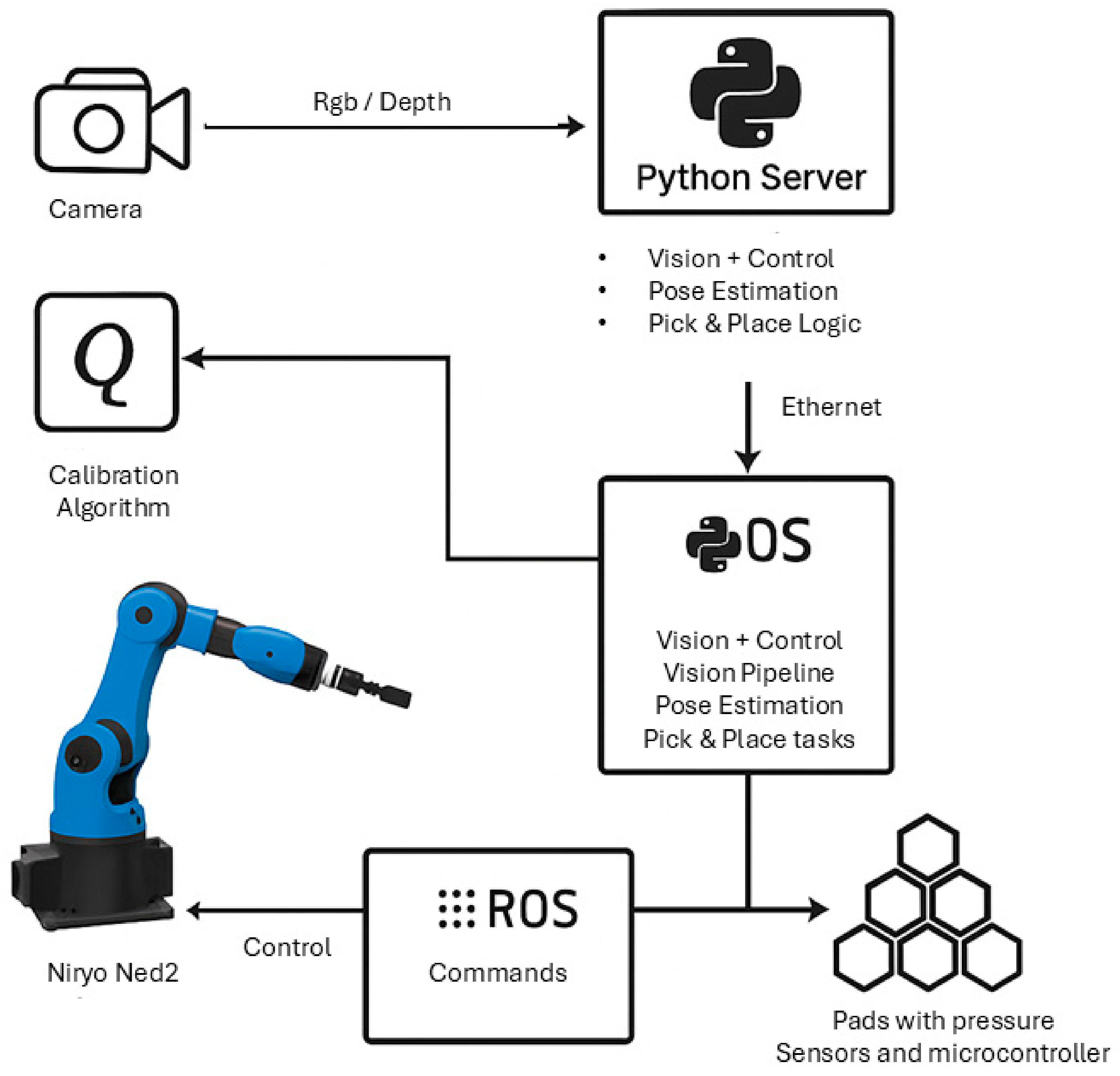
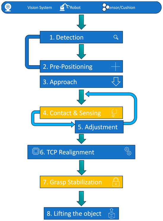
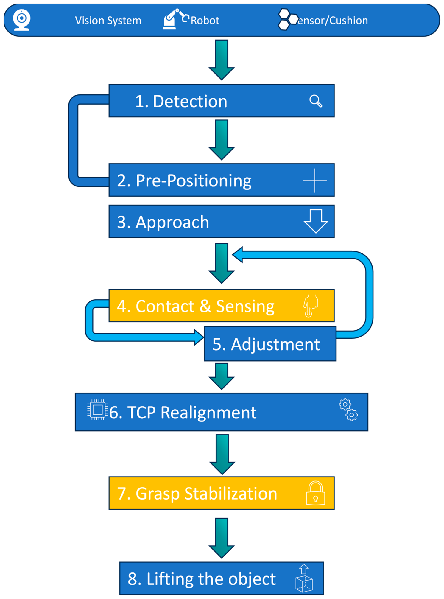
The adjustment mechanism uses feedback from the sensors to refine the grasp during contact. Unlike conventional rigid and soft grippers that rely on fixed trajectories or global actuation, the baromorphic system uses contact information to adapt its pose actively throughout the grasping sequence. This results in a more stable and gentler interaction with irregular objects, contributing to improve grasp reliability while reducing the likelihood of mechanical stress or damage. The conceptual progression of this process, from the visually guided approach to the contact-driven corrections and final stabilisation, is illustrated in Figure 6, the logical flow is in Figure 7.
Figure 6.
Workflow layout.
Figure 7.
Picking logic flowchart.
3.4. System Integration and Workflow
The experimental prototype integrates sensing, actuation, and control within a unified hardware–software framework designed to support the baromorphic gripping mechanism and is described in Figure 8. An ATMEGA 2560 Microcontroller is responsible for acquiring data from the embedded WSEN-PDUS [21] pressure sensors, which capture the local deformation state within selected cells of the array. The present embodiment uses grouped pneumatic channels and sparse sensing for experimental feasibility, consistent with the component-level characterisation reported in our prior work [8]. Pneumatic actuation is implemented through manually operated syringes in this proof-of-concept stage, a choice that simplifies evaluation of cell mechanics while allowing for modulation of internal pressure. Future iterations will incorporate compact electronically controlled valves for automated actuation. As validated in our prior sensor characterisation study [10], the structural overpressure of 103 kPa induced by manual syringe actuation remains within the safe mechanical tolerance of the embedded WSEN-PDUS unit. In that work, the sensorised hexagonal cushion was tested with controlled syringe strokes in the embedded air channel, producing a polynomial pressure–response calibration (R2 = 0.982) and confirming stable electromechanical behaviour beyond the nominal 0–100 kPa output span without compromising the sensor housing or sensing membrane. For this proof-of-concept, two WSEN-PDUS pressure sensors (nominal calibrated range, 0–100 kPa) were embedded in diametrically opposed peripheral cells on the outer ring of the hexagonal array. These peripheral locations were selected because they establish first contact with tapered produce and because the bilateral pressure difference provides an efficient indicator of lateral misalignment. Only a subset of cells was instrumented to evaluate whether the relative pressure asymmetry is sufficient to drive TCP dynamic realignment; full-array instrumentation is reserved for future design iterations.
Figure 8.
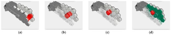
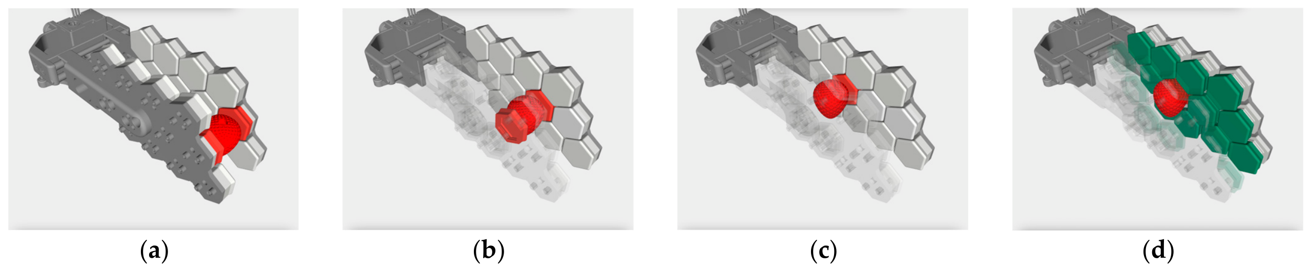
Pick and place operation. (a) Initial approach and first red cell activated by pressure, (b) second cell activated by pressure, (c) third and final cell activated by pressure, (d) final gripping—the green cells are inflated and create a cage around the product.
It is important to distinguish explicitly between the theoretical scalable architecture and the physical experimental prototype tested in this study. The theoretical architecture envisages independently addressable pneumatic cells, each with dedicated actuation and sensing, so that local compliance can be scaled cell by cell across larger arrays. By contrast, the present laboratory embodiment groups cells into shared pneumatic lines and instruments only a sparse subset of the array; this simplification was adopted for experimental feasibility and does not claim to validate a fully independent multi-channel industrial product. The component-level sensor and cushion characterisation supporting this sensing strategy, including the WSEN-PDUS embedding and pressure-response calibration under controlled syringe loading, is reported in our prior IROS study [10] and related design work [8]. Subsequent steps will therefore migrate from manual syringes and grouped lines to proportional solenoid valves, closed-loop pressure regulation, and progressively independent cell addressing. Overall, the present work remains a proof-of-concept of the perception-sensing TCP realignment pipeline, not a final prototype validation for field deployment.
The control architecture is implemented within the Robot Operating System (ROS) inside the Niryo NED2, and within a Python 3.10 process which manages communication across the perception, sensing, and actuation modules. The vision system provides the initial detection and pose estimation of the target, and this information is transmitted to the ROS core, which coordinates the motion planning and execution carried out by the robotic platform. As the end-effector approaches and begins to interact with the object, the pressure sensors generate real-time data that is streamed to the microcontroller. The microcontroller processes the pressure asymmetries, which serve as indicators of misalignment between the Tool Centre Point and the object’s actual geometry. The resulting TCP dynamic realignment commands are then communicated back to the robot through ROS, enabling the TCP to be adjusted while contact is ongoing.
Through this closed-loop interaction, the system continuously refines its pose until a stable and balanced grasp is achieved. The combination of visual initialisation and sensor-driven correction ensures that the gripper adapts to irregular geometries and compensates for positional inaccuracies before the lifting phase begins. The complete operational sequence, encompassing perception, approach, contact, realignment and stabilisation, is summarised in the corresponding workflow diagram.
The gripping process begins with the detection phase, where the vision system identifies the target object within the operational environment and computes its precise centroid (cX, cY). Once these coordinates are obtained, the system moves to pre-positioning: the robot transfers its TCP (Tool Centre Point) to a precise point directly above (cX, cY), maintaining a predefined Z-offset. Subsequently, the approach phase is initiated, during which the robot begins its controlled descent toward the object. As the cushion cells make physical contact with the object, the Contact & Sensing phase is activated. The pressure data generated by this contact is immediately streamed to the controller. This sensory data serves as the input for TCP dynamic realignment: a control algorithm processes it to calculate an updated TCP pose, thereby compensating for any initial positional inaccuracies or geometric irregularities of the object. The robot arm then executes the TCP dynamic realignment, moving dynamically and precisely toward this newly calculated pose. The system then transitions to grasp stabilisation: the inflation level (or gripping force) is slightly continued, and a final, fine TCP dynamic realignment is performed to securely lock the object. Finally, the object, now firmly secured, is lifted in the lift phase, successfully completing the entire gripping sequence.
This closed-loop routine produces the behaviour illustrated in Figure 8, where the object is progressively detected, centred, and mechanically “felt” by the hexagonal sensor array. As contact information accumulates, the gripper incrementally adapts its shape and TCP pose, allowing the object to be gradually enveloped and stabilised within the grasp. This results in a robust, self-correcting capture process that compensates for irregular geometries, offsets, and uncertainties before the lift phase.
4. Comparative Performance Tests
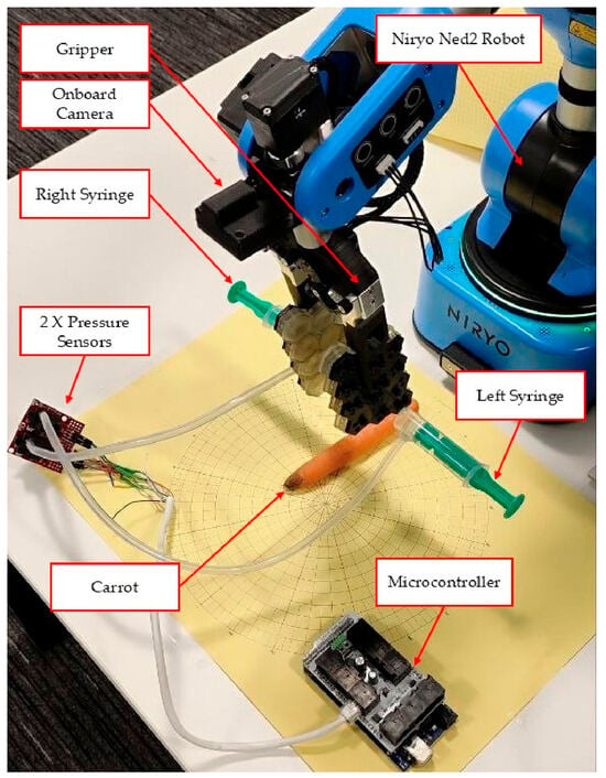
The performance of the baromorphic end-effector was assessed through a series of experiments aimed at evaluating its robustness, adaptability, and comparative effectiveness with respect to commonly used commercial grippers. These experiments, carried out during the preparation of paper [9], were designed to validate the operational principles of the proposed system under controlled yet representative manipulation conditions. A grasp was defined as successful only if the object was lifted and held for at least 5 s without observable slip or drop; otherwise, the trial was recorded as a failure. All trials were conducted on the Niryo Ned2 to maintain consistent kinematic conditions. The experimental arrangement is shown in Figure 9. The baromorphic gripper was evaluated across 12 distinct spatial configurations (one grasp per configuration) and 11 distinct angular configurations (one grasp per orientation). It is essential to note that, although air was supplied manually, the operator acted solely as a blind pressure source. All spatial corrections (robot arm motion) were executed fully autonomously by the sensor-based closed-loop algorithm, demonstrating that the control logic is independent of operator bias. A conventional rigid parallel-jaw gripper was evaluated as an industrial baseline on a centred pose with ten repeated attempts, all unsuccessful. These results demonstrate functional feasibility under heterogeneous misalignment conditions; they do not constitute a statistically powered A/B benchmark.
Figure 9.
Experiment layout, reprinted from ref. [9].
To establish an industrial baseline, a widely adopted rigid parallel-jaw gripper was tested on the same carrot-picking task. This object was selected because its irregular geometry, tapered profile and low-friction surface present a challenging scenario for conventional grippers. Baseline trials were conducted on the Niryo NED2 under laboratory conditions; the rigid gripper completed ten repeated attempts on a nominally centred pose and failed in all cases.
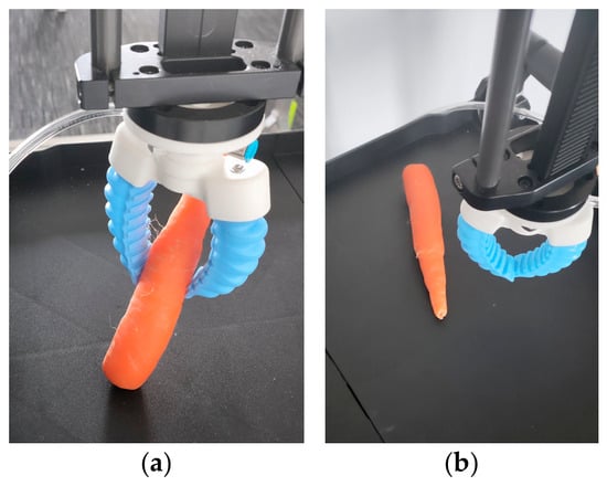
The first comparison involved a standard parallel rigid gripper. Across all attempts, the device was unable to secure a successful grasp, as indicated conceptually. Although the rigid jaws sometimes achieved initial contact, the gripper could not maintain stable engagement due to the irregular shape and smooth surface of the carrot, which frequently caused slippage as soon as lifting was initiated. In cases where the approach was slightly misaligned, the rigid structure applied concentrated point pressures that displaced the object laterally rather than enclosing it, revealing a limited tolerance to positional error and a lack of adaptability to morphological variability, as shown in Figure 10a,b. The rigid gripper test serves purely as an industrial baseline to demonstrate the inadequacy of traditional contact geometries in agriculture, and not as a benchmark for the control algorithm.
Figure 10.
Commercia gripper picking test: Carrot picking (a), picking fail (b).
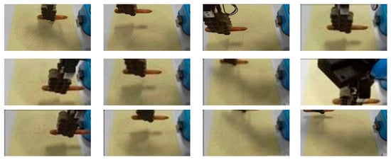
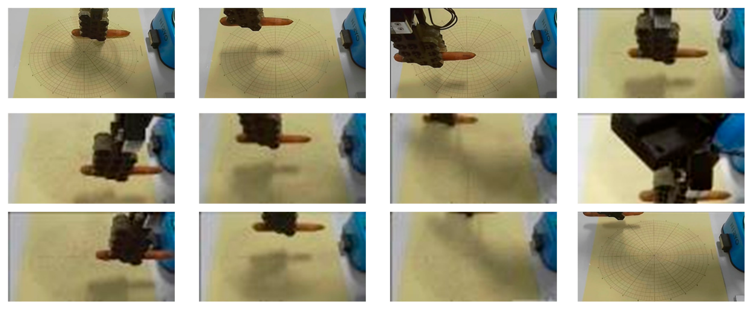
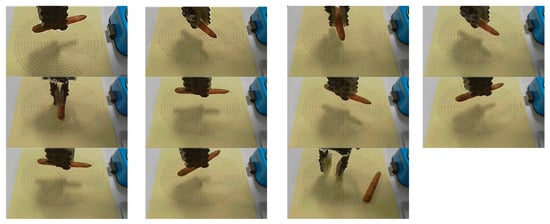
The baromorphic system was evaluated further by commanding the robot to known positions, with the target object placed at twelve distinct locations within the robot’s workspace, each defined by different combinations of the coordinates (x, y). This configuration enabled an assessment of the system’s ability to accommodate spatial variability, a typical characteristic of agricultural environments where produce is rarely presented in a fixed or repeatable position. Across all twelve locations, the system successfully grasped and lifted the carrot, resulting in a complete success rate. Across all tested configurations, which spanned positive and negative displacements on both axes, the system consistently achieved successful grasps. The tested positions ranged from moderate offsets of around ±50 mm to more extreme placements exceeding ±130 mm in either direction, demonstrating the gripper’s capacity to tolerate significant spatial variability. Even under challenging conditions, such as boundary cases where image distortion affected the camera’s perception, or instances where the carrot was partially out of frame, the system still completed the grasping task without failure. Minor anomalies were noted, including a near-collision event at the limits of the camera’s field of view and one suboptimal pick caused by incomplete object visibility, yet neither resulted in task failure. Figure 8 illustrates the pick-and-place grasp sequence, while Figure 11 shows snapshots of the experimental sequence summarised in Table 2 [9].
Figure 11.
Snapshots of the experiment in Table 2, reprinted from ref. [9].
Table 2.
Summary of linear movement experiment, reprinted from ref. [9].
The consistent performance observed across all placements highlights the system’s tolerance to positional deviations. This robustness stems from the combination of the initial pose estimation provided by the vision module and the subsequent refinements introduced by the TCP dynamic realignment algorithm, which compensates for residual misalignment once contact begins. Together, these mechanisms allow the end-effector to maintain reliable grasping behaviour even when the object is not precisely centred within the expected pickup region.
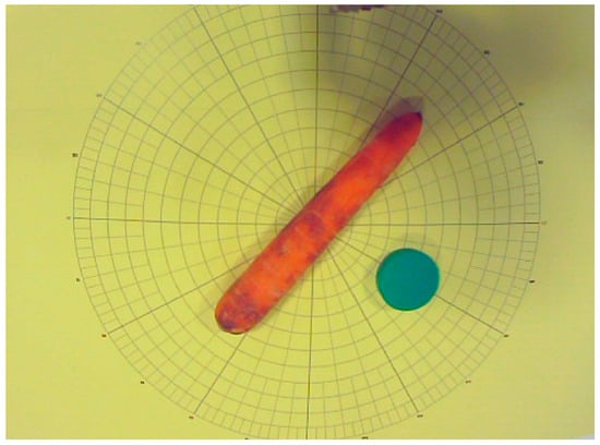
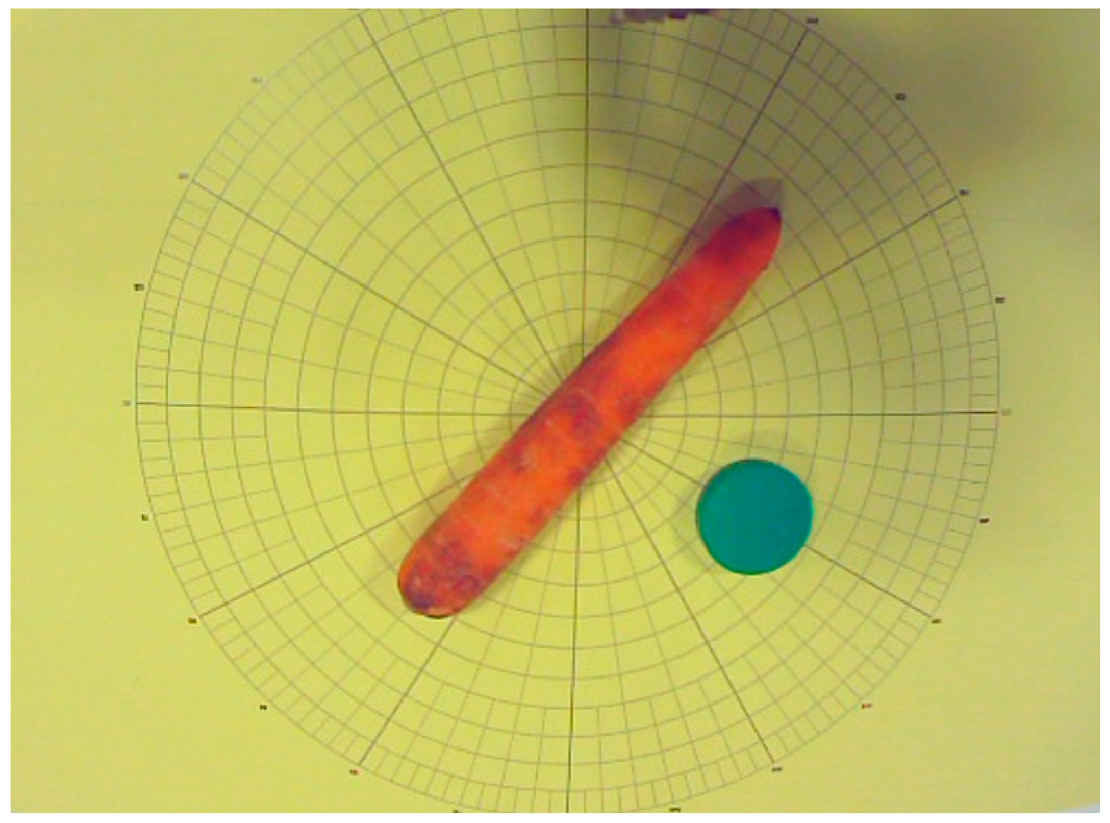
Angular tests were also carried out by placing the carrot in a series of randomly chosen orientations spanning angles from minus ninety degrees to plus ninety degrees relative to the robot’s approach axis, as shown in Figure 12.
Figure 12.
Angular test environment.
The angular evaluation further examined the robustness of the baromorphic end-effector by placing the carrot at a set of randomly assigned orientations spanning from approximately −90 degrees to +90 degrees relative to the robot’s approach axis, as illustrated in Figure 10. This configuration introduced substantial rotational variability, reproducing conditions common in agricultural environments, where produce rarely presents in a consistent or ideal orientation.
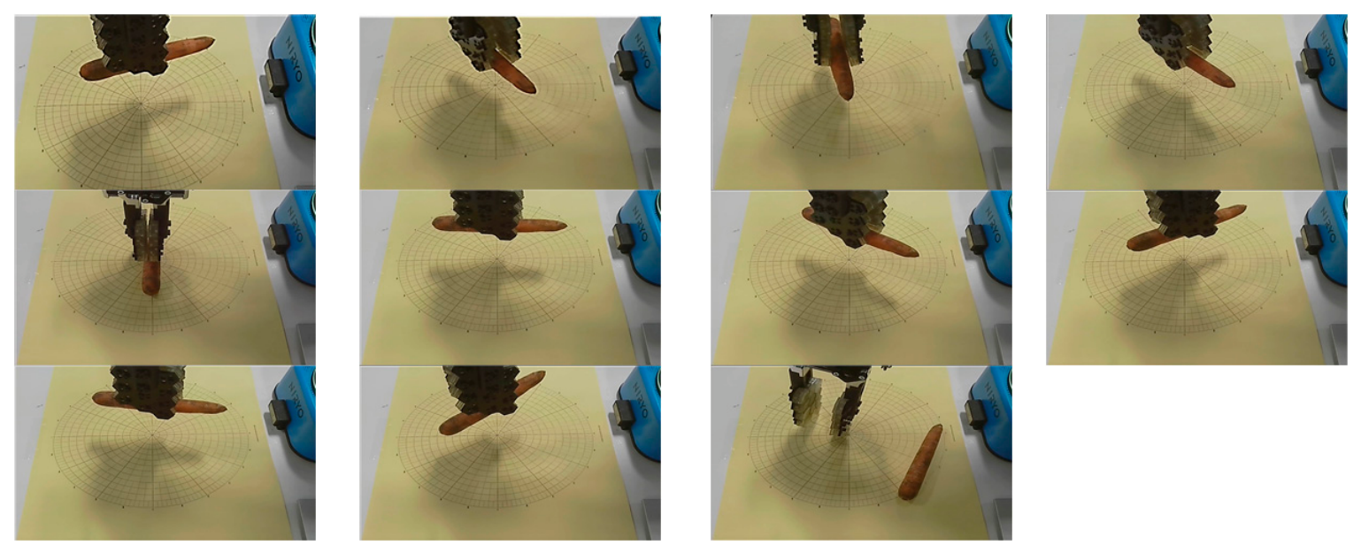
Across the tested cases, the system demonstrated a high level of adaptability. Out of eleven trials, nine resulted in fully successful grasps, yielding an overall success rate of eighty-two percent. The successful attempts covered a broad spectrum of orientations, including moderate angles, such as ±20–40 degrees, and even more challenging positions beyond +80 degrees or slightly off-axis initialisations. In several instances, particularly around −21 degrees and +83 degrees, the carrot was not centred within the gripper’s initial capture region, yet the system still completed the grasp thanks to the compensatory behaviour of the baromorphic cells. These situations underline the value of the compliant structure, which mitigates errors arising from imperfect alignment before and during contact.
The two failed trials occurred at the most extreme negative angles, specifically around −86 degrees and −65 degrees, where the Tool Centre Point was not calibrated to incorporate wrist rotation. Under these conditions, the approach trajectory led to minor collisions or incomplete engagement, preventing successful grasp formation. Additional anomalous behaviours, such as unintended back-picks observed at approximately −28 degrees, were likewise attributable to the absence of rotational compensation rather than deficiencies in the gripper’s intrinsic design. These outcomes, detailed in Table 3 and documented visually in Figure 13, highlight that the primary limiting factor in the tested configuration was the lack of dynamic TCP orientation control rather than limitations of the baromorphic mechanism itself. Accordingly, the demonstrated operational envelope should be understood as planar TCP translation with contact-driven correction, not full 6-DoF pose optimisation. Integration of rotational TCP calibration is identified as a necessary extension for reliable operation at extreme orientations.
Table 3.
Summary of angle experiment, reprinted from ref. [9].
Figure 13.
Snapshots of the angular experiment in Table 3, reprinted from ref. [9].
Overall, the results indicate that the system exhibits strong resilience to angular misalignment. Even without dedicated rotational adjustment, the combination of compliant hexagonal cells and pressure-driven feedback enabled the gripper to correct substantial pose discrepancies during the contact phase. A conceptual representation of the evaluated orientations and the associated results is provided in Table 3, illustrating both the breadth of the tested angular range and the specific conditions leading to successful or failed grasps. These findings support the conclusion that, with full TCP rotational integration, performance under extreme orientations is likely to further improve, reinforcing the suitability of the baromorphic end-effector for real-world agricultural harvesting tasks.
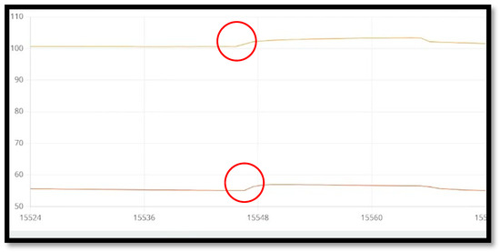
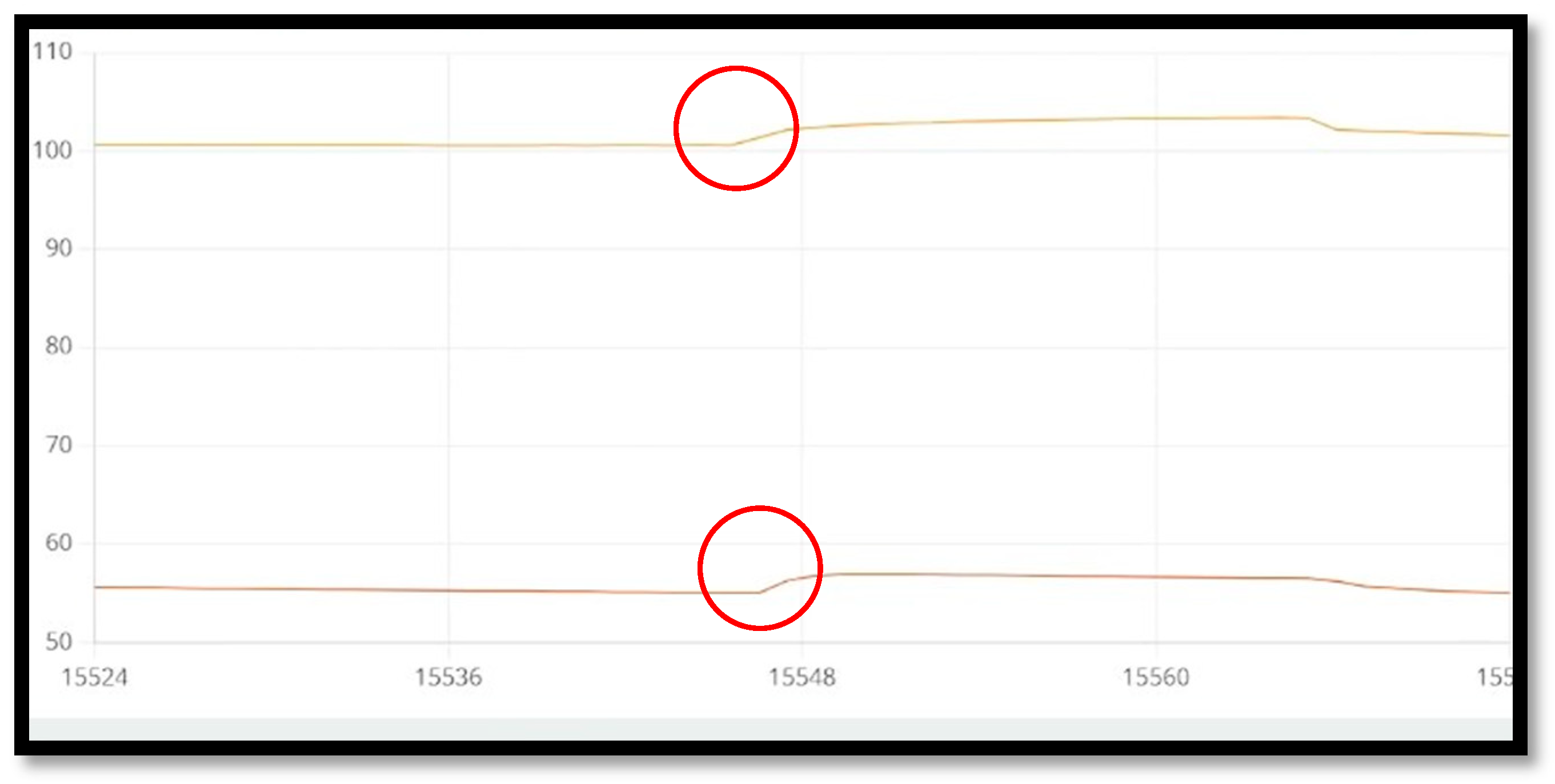
A detailed examination of a representative grasping sequence was carried out by analysing a single successful test lasting approximately 18 s. The approximate stage durations were: detection and pre-positioning, ~3 s; approach and first contact, ~5 s; TCP dynamic realignment and grasp stabilisation, ~7 s; lift, ~3 s. These laboratory cycle times are not claimed as field-throughput targets under manual pneumatic actuation. The corresponding pressure data from the two active sensorised cells are shown in Figure 14 [9]. At the beginning of the sequence, the left and right sensors displayed different baseline values, around 55 kPa and 100 kPa, respectively, due to manual pre-loading introduced during the setup. The critical moment occurred at roughly 8.36 s, when both sensors exhibited a concurrent rise in pressure, increasing to about 58 kPa and 103 kPa. This simultaneous change indicates that the gripper established stable contact with the object and that the grasp had formed reliably. As validated in our prior sensor characterisation study [10], this brief 103 kPa structural overpressure induced by manual syringe pre-loading remained within the safe mechanical tolerance established for the embedded WSEN-PDUS architecture during cushion-level electromechanical testing. The behaviour of the signals confirms the correct functioning of the tactile feedback mechanism, which detects and interprets contact conditions in real time.
Figure 14.
Experimental setting with a carrot: Sensor value peaks.
Following the moment of contact, a final adjustment of the Tool Centre Point was executed along the vertical axis. This correction corresponded to a displacement of approximately 22.5 mm, a distance equivalent to the height of one cell in the array. This refinement improved the load distribution and contributed to the stabilisation of the grip before the lifting phase began. The sequence recorded in Figure 12 illustrates how the pressure evolution over time reflects the transition from initial approach to stable grasp formation.
5. Discussion
The present prototype was validated on a Niryo NED2 platform under controlled laboratory conditions. The linear positional tests achieved 12/12 successful grasps for offsets of up to ±170 mm; the angular tests achieved success 9/11 times (82%). Each spatial and angular configuration was tested once (N = 1 per condition) on a single object’s morphology; the reported rates therefore constitute a first validation of logical feasibility rather than a statistical reliability assessment. Only two cells were instrumented, and pneumatic actuation remained manual.
Because of this manual syringe actuation, a formal blind ablation study (disabled versus enabled TCP dynamic realignment) would introduce unacceptable operator bias: the operator could visually compensate for misalignment by delivering more air to selected cells. For this reason, no ablation trial was conducted in the present manuscript.
The reported success rates must therefore be interpreted as the combined outcome of passive geometric compliance and active TCP dynamic realignment, rather than as an isolated quantification of either mechanism alone.
A controlled ablation study is planned for subsequent work after replacing the manual syringes with proportional solenoid valves and closed-loop pressure regulation, enabling algorithm-enabled and algorithm-disabled trials under matched pneumatic inputs.
Although ablation is absent here, passive rubber deformation alone cannot physically translate the macroscopic pose of a rigid manipulator. The observed macroscopic X–Y re-centring of the Niryo arm during contact therefore provides physical evidence that the active TCP dynamic realignment algorithm was engaged and contributed decisively to grasp success. This argument concerns the planar closed-loop correction demonstrated in this work; wrist-orientation control remains outside the present control loop and is acknowledged as a separate limitation for extreme angular cases.
The transition from laboratory proof-of-concept to practical agricultural deployment will involve: (i) migration from SLA validation parts to fatigue-resistant TPU/silicone elastomers; (ii) replacement of manual syringe actuation with solenoid valves and closed-loop pressure servos; (iii) environmental robustness against humidity, dust, UV, and temperature drift; (iv) integration with higher-DoF manipulators, including wrist-orientation control; and (v) statistically powered field trials. The contribution of this manuscript is establishing the cell-level sensing-and-correction principle upon which these engineering layers can be built.
The proposed baromorphic end-effector addresses long-standing challenges in adaptive agricultural harvesting, particularly those related to variability in geometry, fragility of produce, and uncertainty in positioning. Early agricultural robotic systems, such as the eggplant harvesting platform reported by Kondo et al. [22], highlighted how rigid or quasi-rigid manipulation strategies struggle to cope with the unstructured nature of agricultural environments.
The effectiveness of the proposed system derives primarily from its baromorphic architecture. The tessellated array of hexagonal pneumatic cells, whose cushion design was optimised using a finite-element analysis in prior work [8], enables localised deformation and a more uniform stress distribution across the contact surface. This directly mitigates the limitations of monolithic soft grippers, which tend to deform globally and lack the spatial resolution required for stable interaction with irregular objects. Similar limitations have been widely discussed in the soft robotics literature, including the pneumatic and chemo-mechanical actuation approaches described by Ilievski et al. [23].
A key differentiating factor is the integration of embedded tactile sensing with real-time Tool Centre Point (TCP) adjustment. By monitoring the bilateral pressure asymmetry from two instrumented cells, the system compensates for positional and angular deviations that commonly arise in agricultural scenarios. This sensory feedback loop strengthens robustness beyond what is achievable through vision alone. In the reported laboratory tests, this combination of compliant deformation, sparse embedded sensing, and dynamic pose correction yielded observed functional improvement relative to the rigid baseline gripper. The observed behaviour is also consistent with recent advances in mechanically programmed and variable-stiffness soft actuators. Systems based on controllable anisotropy, such as the fibre angle-tuned designs reported by Connolly et al. [24], underline the importance of local mechanical modulation for reliable grasping. Likewise, Wang et al. [18] emphasised that adaptive manipulation requires localised compliance and real-time modulation of mechanical behaviour, capabilities that remain only partially realised in most existing soft grippers.
From a systems perspective, the integration of vision-based initialisation with tactile refinement mirrors human grasping strategies, where visual cues guide coarse positioning and tactile feedback governs fine alignment. While the vision module provides a coarse initial estimate of object location, the subsequent TCP dynamic realignment driven by pressure asymmetry compensates for the perception uncertainty and object variability. This two-stage approach was critical in achieving full success in the linear displacement tests and 9/11 successful attempts in the angular orientation tests, whereas the rigid baseline gripper failed all attempts. It is important to notice that the current prototype remains a proof-of-concept: manual pneumatic actuation, sparse sensing, and platform-level orientation limits define the present operational envelope.
6. Conclusions
The design, implementation, and experimental evaluation of a baromorphic end-effector for adaptive agricultural harvesting are introduced. The system combines a modular array of sensorised hexagonal pneumatic cells with vision-based initialisation and real-time TCP dynamic realignment, enabling the gentle yet stable grasping of irregular and delicate produce. The primary objective was to validate the feasibility of an integrated perception-sensing TCP realignment pipeline, rather than to present a commercially optimised agricultural product.
The experimental results demonstrate that distributed deformation and embedded tactile feedback, when coupled with an adaptive, singularity-free visual descent controller, show preliminary laboratory feasibility. The ability to locally adapt the contact geometry and dynamically correct the end-effector pose proved decisive in achieving reliable grasping across varying object positions and orientations.
The modular hexagonal architecture represents a scalable and flexible design strategy, supporting future extensions in both hardware and control. By treating cells as modular actuator units—with sparse sensing in the present prototype—the architecture offers a path toward higher spatial resolution without the control complexity typical of monolithic soft structures.
Although the current prototype shows promising performance, the findings should be considered preliminary. Future works will integrate miniaturised pneumatic control, increase sensor density, and validate durability under real field conditions. Advances in distributed control and learning-based strategies will further enhance adaptability and robustness.
Overall, the laboratory results support the feasibility of combining a modular baromorphic cell array with sparse pressure-sensing and closed-loop TCP dynamic realignment for adaptive grasping of irregular produce under controlled conditions. Further work is required before claiming its readiness for automated field harvesting, including actuation automation, denser sensing, durability validation, and statistically powered multi-object trials.
Author Contributions
Conceptualization, D.C. and N.A.K.; methodology, D.C. and N.A.K.; software, D.C. and N.A.K.; validation, D.C. and N.A.K.; formal analysis, D.C. and N.A.K.; investigation, D.C. and N.A.K.; resources, D.C.; data curation, D.C. and N.A.K.; writing—original draft preparation, D.C. and N.A.K.; writing—review and editing, DC and N.A.K.; visualization, D.C. and N.A.K.; supervision, D.C.; project administration, D.C.; funding acquisition, D.C. All authors have read and agreed to the published version of the manuscript.
Funding
This research received no external funding.
Data Availability Statement
Data is contained within the article.
Conflicts of Interest
The authors declare no conflict of interest.
References
- United Nations, Department of Economic and Social Affairs, Population Division. World Population Prospects 2019: Highlights (ST/ESA/SER.A/423); United Nations: New York, NY, USA, 2019. [Google Scholar]
- Godfray, H.C.J.; Beddington, J.R.; Crute, I.R.; Haddad, L.; Lawrence, D.; Muir, J.F.; Pretty, J.; Robinson, S.; Thomas, S.M.; Toulmin, C. Food security: The challenge of feeding 9 billion people. Science 2010, 327, 812–818. [Google Scholar] [CrossRef] [Scilit] [PubMed]
- FAO. The Future of Food and Agriculture—Trends and Challenges; FAO: Rome, Italy, 2017. [Google Scholar]
- Bac, C.W.; van Henten, E.J.; Hemming, J.; Edan, Y. Harvesting robots for high-value crops: State-of-the-art review and challenges ahead. J. Field Robot. 2021, 38, 513–531. [Google Scholar]
- Van Henten, E.J.; van’t Slot, D.A.; Hol, C.W.J.; van Willigenburg, L.G. Optimal manipulation of plant stems in cut-tulip harvesting. Comput. Electron. Agric. 2002, 33, 1–21. [Google Scholar]
- Rus, D.; Tolley, M.T. Design, fabrication and control of soft robots. Nature 2018, 521, 467–475. [Google Scholar]
- Shintake, J.; Cacucciolo, V.; Floreano, D.; Shea, H. Soft robotic grippers. Adv. Mater. 2018, 30, 1707035. [Google Scholar] [CrossRef] [Scilit] [PubMed]
- Al Khatib, N.; Cafolla, D. Embracing the gentle touch: Design and simulation of an intelligent soft fingertip for adaptive agricultural harvesting. In Proceedings of the International Conference on Robotics in Alpe-Adria Danube Region; Springer Nature: Cham, Switzerland, 2024; pp. 515–522. [Google Scholar]
- Al Khatib, N.; Cafolla, D. From Vision to Grasp: Agricultural Product Recognition and Manipulation Trough TCP Dynamic Realignment. In Proceedings of the I4SDG Workshop 2025—IFToMM for Sustainable Development Goals; Carbone, G., Quaglia, G., Eds.; I4SDG 2025. Mechanisms and Machine Science; Springer: Cham, Switzerland, 2025; Volume 179. [Google Scholar]
- Al Khatib, N.; Cafolla, D. Development and Characterization of an Adaptive Baromorphic End-Effector for Precision Agricultural Handling. In Proceedings of the IEEE/RSJ International Conference on Intelligent Robots and Systems (IROS), Hangzhou, China, 19–25 October 2025; pp. 2998–3003. [Google Scholar]
- Lei, J.; Ge, Z.; Fan, P.; Zou, W.; Jiang, T.; Dong, L. Design and Manufacture of a Flexible Pneumatic Soft Gripper. Appl. Sci. 2022, 12, 6306. [Google Scholar] [CrossRef] [Scilit]
- Mawah, S.C.; Park, Y.-J. Tendon-Driven Variable-Stiffness Pneumatic Soft Gripper Robot. Robotics 2023, 12, 128. [Google Scholar] [CrossRef] [Scilit]
- Harrell, R.C.; Adsit, P.D.; Nadler, M. Agricultural robotics. In Handbook of Industrial Robotics, 2nd ed.; Nof, S.Y., Ed.; John Wiley & Sons, Inc.: Hoboken, NJ, USA, 1999; pp. 1195–1208. [Google Scholar]
- Shamshiri, R.R.; Kalantari, F.; Ting, K.C.; Thorp, K.R.; Hameed, I.A.; Weltzien, C.; Ahmad, D.; Shad, Z.M. Research and development in agricultural robotics: A perspective of digital farming. Int. J. Agric. Biol. Eng. 2018, 11, 1–14. [Google Scholar] [CrossRef]
- Brown, E.; Rodenberg, N.; Amend, J.; Mozeika, A.; Steltz, E.; Zakin, M.R.; Lipson, H.; Jaeger, H.M. Universal robotic gripper based on the jamming of granular material. Proc. Natl. Acad. Sci. USA 2010, 107, 18809–18814. [Google Scholar] [CrossRef] [Scilit]
- Polygerinos, P.; Correll, N.; Morin, S.; Mosadegh, B.; Onal, C.D.; Petersen, K.; Cianchetti, M.; Tolley, M.; Shepherd, R. Soft Robotics: Review of Fluid-Driven Intrinsically Soft Devices; Manufacturing, Sensing, Control, and Applications in Human-Robot Interaction: Review of Fluid-Driven Intrinsically Soft Robots. Adv. Eng. Mater. 2017, 19, e201700016. [Google Scholar] [CrossRef] [Scilit]
- Yogeswaran, N.; Dang, W.; Navaraj, W.T.; Shakthivel, D.; Khan, S.; Polat, E.O.; Gupta, S.; Heidari, H.; Kaboli, M.; Lorenzelli, L.; et al. New materials and advances in making electronic skin for interactive robots. Adv. Robot. 2015, 29, 1359–1373. [Google Scholar] [CrossRef] [Scilit]
- Wang, T.; Hao, Y.; Yang, X.; Wen, L. Soft robotics: Structure, actuation, sensing and control. J. Mech. Eng. 2017, 53, 1–13. [Google Scholar] [CrossRef] [Scilit]
- Liu, Y.; Hou, J.; Li, C.; Wang, X. Intelligent Soft Robotic Grippers for Agricultural and Food Product Handling: A Brief Review. Adv. Intell. Syst. 2023, 5, 2300233. [Google Scholar] [CrossRef] [Scilit]
- Jocher, G.; Qiu, J.; Chaurasia, A. Ultralytics YOLO (Version 11.0.0) [Software]. Ultralytics. 2023. Available online: https://github.com/ultralytics/ultralytics (accessed on 12 December 2025).
- Wurth Elektronik. WSEN-PDUS Sensor Datasheet. 10 October 2025. Available online: https://www.we-online.com (accessed on 20 August 2024).
- Kondo, N.; Monta, M.; Fujiura, T. Robotic harvesting system for eggplants. Comput. Electron. Agric. 2000, 25, 133–148. [Google Scholar]
- Ilievski, F.; Mazzeo, A.D.; Shepherd, R.F.; Chen, X.; Whitesides, G.M. Soft robotics for chemists. Angew. Chem. Int. Ed. 2011, 50, 1890–1895. [Google Scholar] [CrossRef] [Scilit] [PubMed]
- Connolly, F.; Polygerinos, P.; Walsh, C.J.; Bertoldi, K. Mechanical programming of soft actuators by varying fiber angle. Soft Robot. 2017, 4, 26–32. [Google Scholar]

Disclaimer/Publisher’s Note: The statements, opinions and data contained in all publications are solely those of the individual author(s) and contributor(s) and not of MDPI and/or the editor(s). MDPI and/or the editor(s) disclaim responsibility for any injury to people or property resulting from any ideas, methods, instructions or products referred to in the content. |
© 2026 by the authors. Licensee MDPI, Basel, Switzerland. This article is an open access article distributed under the terms and conditions of the Creative Commons Attribution (CC BY) license.