


Abstract
In this paper, an estimation algorithm for human interaction forces is presented, which can potentially be applied when a Parallel Kinematic Manipulator (PKM) is used on supervised physiotherapy exercises. The estimation algorithm is based on the dynamic model of the PKM, which is calculated with a 3-RRRS configuration (three arms with three rotational joints and a spherical joint); the underline denotes the active joints. The proposed algorithm estimates human interaction forces only in terms of the calculation of the robot dynamic state and control signals of the active joints of the PKM, without the need of force or torque sensors; therefore, the proposed method reduces the complexity, inertia and passive mass associated with the addition of 6-DOF force/torque sensors. A full description of the design of the robotic platform is also presented, followed by a validation test of estimated data against measured forces and relevant experimental results for static and dynamic tests.
1. Introduction
Muscle strength estimation constitutes one of the most important clinical indicators during neurological, orthopedic and geriatric rehabilitation processes, since it provides valuable information regarding motor recovery, functional capacity and treatment effectiveness. Accurate assessment of muscular force allows therapists to monitor patient progression, adjust therapeutic intensity and quantify functional improvements throughout the rehabilitation process.
The procedures used to monitor the progress of a patient during physiotherapy exercises can be classified into three main categories: Manual Testing, Instrumented Methods and Robot-Assisted Estimation. In the next subsections, the authors present a brief state-of-the-art study organized using this classification.
1.1. Manual Testing
Traditionally, muscular force assessment has been performed using qualitative clinical procedures that do not require specialized instrumentation, allowing their implementation in hospitals, rehabilitation centers and low-resource environments. Among these methods, Manual Muscle Testing (MMT), also known as the Medical Research Council (MRC) scale or Oxford scale, remains one of the most widely adopted approaches in clinical practice [1,2]. In this technique, therapists apply manual resistance to a specific muscle group and classify the patient’s ability to overcome such resistance using an ordinal scale ranging from 0 to 5. Due to its simplicity, low cost and rapid implementation, MMT continues to be considered one of the reference clinical tools for the assessment of neuromuscular and musculoskeletal disorders [3].
Several review studies have analyzed the reliability and reproducibility of MMT, reporting moderate to high intra-rater and inter-rater agreement depending on the evaluated muscle group, therapist expertise and testing protocol employed [1,4]. Nevertheless, systematic reviews have shown that the subjective nature of MMT limits its sensitivity for detecting subtle changes in muscle strength, particularly in patients presenting mild weakness or during early stages of rehabilitation, where quantitative assessment becomes clinically relevant [4].
In addition to MMT, therapists frequently employ functional performance tests to indirectly estimate force generation capabilities in the lower limbs. Common examples include the Five Times Sit-to-Stand Test (FTSST), the 30-Second Sit-to-Stand Test (30sSTS), the Timed Up and Go (TUG) test and stair-climbing evaluations [5,6,7]. These methodologies assess the patient’s ability to perform activities of daily living and provide indirect information regarding muscular deficits, postural control, balance impairments and functional independence.
Other qualitative assessment strategies include direct observation of movement patterns, evaluation of the ability to overcome gravity, fatigue assessment and identification of compensatory motor strategies during specific rehabilitation exercises. Clinical evaluation may also include palpation techniques, manual resistance tests and therapist-guided functional tasks designed to identify asymmetries and deficiencies in muscular recruitment patterns [8].
Although these approaches present high clinical utility due to their simplicity, rapid implementation and low cost, they suffer from important limitations in terms of objectivity, resolution and repeatability among evaluators [1,4]. These limitations have motivated the development of quantitative methodologies based on biomechanical instrumentation, physiological sensors and robotic rehabilitation systems capable of providing objective, repeatable and highly sensitive measurements of muscular force and human motor performance.
1.2. Instrumented Methods
In situations requiring quantitative analysis, several sensors and estimation techniques can be used to measure or estimate forces, such as Surface Electromyography (sEMG), force platforms, Inertial Measurement Units (IMUs), biomechanical models, and robotic systems. Quantitative assessment of the forces generated by the limbs has evolved from direct physiological and mechanical measurements toward methodologies that combine wearable sensors, biomechanical models, and robotic systems. Unlike clinical scales and functional performance tests, Instrumented Methods provide continuous variables associated with muscle activation, external forces, joint moments, and the physical interaction between the user and a device. Depending on the measurement principle and the available variables, these methods can be broadly classified into electrophysiological techniques, mechanical measurement systems, wearable inertial sensors, biomechanical model-based methods, and robot-assisted assessment systems.
Surface Electromyography (sEMG) is one of the most widely used non-invasive techniques for characterizing muscle activation and using this information as a basis for force estimation. Staudenmann et al. analyzed the main methodological aspects involved in sEMG-based force estimation and reported that, since the force produced by individual muscles cannot be directly measured using non-invasive procedures, the amplitude of the electromyographic signal can be used to indirectly estimate muscular contribution [9]. However, the relationship between EMG amplitude and muscle force is influenced by physiological and methodological factors, including motor-unit characteristics, the spatial representativeness of the electrodes, and signal-processing procedures. These limitations have motivated the integration of electromyographic information with biomechanical and musculoskeletal models to improve the estimation of internal forces.
In this context, biomechanical model-based methods provide an alternative for estimating muscle forces that cannot be directly obtained from external measurements. Schellenberg et al. reviewed different techniques for the in vivo estimation of lower-limb muscle forces during strength-training tasks, including forward-dynamics, inverse-dynamics, and electromyography-informed modeling approaches [10]. In these methods, measurable kinematic and kinetic variables are combined with the mechanical and musculoskeletal properties of the human body to estimate the internal forces responsible for movement. Consequently, these approaches extend the assessment beyond the measurement of external forces and provide information regarding the mechanical contribution of muscles and joints during the execution of a task.
Force platforms and instrumented mechanical measurement systems, in contrast, allow external forces generated during functional activities to be measured directly. Shahabpoor and Pavic conducted a systematic review of technologies used to measure ground reaction forces during walking and classified the available methods into direct measurement techniques, kinematics-based estimation methods, and plantar-pressure-based systems [11]. Force platforms provide quantitative measurements of force components and other variables associated with the interaction between the subject and the ground and are therefore widely used as reference systems in biomechanical studies. Nevertheless, conventional force-platform measurements generally require controlled environments and restrict the analysis to the instrumented region, limiting their applicability to prolonged assessments or measurements performed outside laboratory settings.
The development of wearable sensors has reduced some of these limitations. In particular, Inertial Measurement Units (IMUs), which integrate accelerometers and gyroscopes, provide information about body-segment motion that can be used to indirectly estimate kinetic variables. Ancillao et al. conducted a systematic review of methods for estimating ground reaction forces and moments using wearable inertial sensors and showed that kinematic variables obtained from these devices can be combined with biomechanical models and computational methods to reconstruct forces and moments during movement [12]. Complementarily, O’Reilly et al. systematically reviewed the use of wearable inertial sensors for lower-limb exercise detection and evaluation, highlighting their ability to quantitatively characterize movement during different functional tasks [13]. Although these systems provide advantages in terms of portability and enable assessment outside laboratory environments, the quality of the resulting estimates depends on factors such as sensor placement and orientation, calibration procedures, and the algorithms used to transform kinematic measurements into biomechanical variables.
1.3. Robot-Assisted Estimation
The incorporation of robotic systems into rehabilitation has further extended these capabilities by allowing the same device to provide mechanical assistance while simultaneously acquiring quantitative information about its interaction with the user. Maggioni et al. reviewed different procedures for robot-aided assessment of lower-extremity functions and showed that rehabilitation robots can use force sensors, load cells, joint variables, and actuator-related signals to evaluate different components of sensorimotor function [14]. In this context, the robot no longer operates exclusively as a movement-assistance device but can also serve as an instrumented platform for characterizing the patient’s mechanical response during a rehabilitation task.
Among these systems, parallel mechanisms represent an architecture of particular interest because of their structural rigidity, multidirectional motion capabilities, and ability to generate different modes of interaction with the limbs. Dong et al. conducted a systematic review of the state of the art in parallel robots for ankle rehabilitation, considering mechanical configurations, actuation methods, control strategies, and training modalities [15]. Their review showed that these systems can incorporate different sources of sensory information and control strategies to perform passive and active exercises, as well as rehabilitation modalities in which the patient’s response influences the behavior of the robotic device. Consequently, information associated with physical human–robot interaction becomes relevant both for patient assessment and for the development of adaptive assistance strategies.
From the perspective of parallel-robot modeling, the closed-loop architecture introduces specific considerations related to kinematics, singularities, force transmission, and dynamic behavior. Rosyid et al. [16] reviewed performance measures for Parallel Kinematic Manipulators, including workspace, dexterity, manipulability, distance to singularity, force transmission, accuracy, stiffness, and dynamic performance. These indices are closely related to the Jacobian matrices of the mechanism and are particularly relevant when velocities, forces, or moments are reconstructed through direct or pseudo-inverse mappings.
Russo et al. [17] provided a comprehensive review of modeling tools for parallel kinematic machines, highlighting loop-closure formulations, inverse and forward kinematics, Jacobian-based velocity analysis, dynamic modeling, error propagation, and calibration. Similarly, Antonov [18] reviewed parallel–serial robotic manipulators and discussed the use of Newton–Euler, Euler–Lagrange, virtual-work, and screw-theory formulations for their analysis. These studies emphasize that no single modeling procedure is universally applicable to every parallel architecture and that the mathematical formulation must be selected according to the geometry, constraints, sensing capabilities, and intended application of the mechanism.
Interaction-force estimation also plays an important role in human–robot coordination and control strategies. Shi et al. analyzed coordination methods used in rehabilitation systems and organized the problem in terms of human–robot system modeling, perception of the user’s motor state, and control strategies [19]. Complementarily, Campagnini et al. conducted a systematic review of control strategies employed in robotic lower-limb rehabilitation after stroke, identifying different approaches based on position, force, and patient–device interaction [20]. In these systems, mechanical information obtained during physical interaction can be used not only to quantify the user’s response but also to modify the assistance provided by the robot according to the user’s participation during movement.
Recent developments have also incorporated multimodal sensor fusion and data-driven methods to increase the number of biomechanical variables that can be estimated. Mohammadi Moghadam et al. combined IMU and EMG signals with machine learning models to predict joint kinematics, joint kinetics, and lower-limb muscle forces [21]. The combination of inertial information, which describes body-segment motion, with electromyographic signals associated with muscle activation enables different sources of physiological and mechanical information to be integrated within a single estimation framework. These approaches represent a transition from systems designed exclusively to measure individual variables toward multimodal methods capable of reconstructing different components of human movement dynamics.
Within rehabilitation robotics, passive and semi-passive mechanisms represent an alternative to conventional actively actuated devices. Washabaugh et al. [22] developed PaRRo, a portable passive rehabilitation robot for functional resistance training of the upper extremity. The mechanism uses kinematic redundancy and eddy-current brakes to generate resistance opposing the user’s movement. The theoretical force-generating capability of the system was evaluated through a mechanical model, while bidirectional load cells installed at the end-effector were used to measure the actual interaction forces during experimental trials. This allowed the authors to compare model-predicted and experimentally measured forces while preserving the passive behavior of the device.
A related passive approach was investigated by Nouri Rahmat Abadi and Hirata [23], who proposed a planar wire-driven support system controlled through servo brakes. In this configuration, the mechanical energy required to move the system is supplied by the human operator rather than by active motors. When the interaction point deviates from a desired path, the braking units regulate the cable forces to oppose the deviation. The controllable workspace and braking strategy were analyzed considering the mechanical restrictions of the system, illustrating how human–robot interaction can be regulated through dissipative elements rather than active actuation.
Although direct force measurement provides explicit information about human–robot interaction, several studies have investigated model-based alternatives that avoid dedicated force/torque sensors. Hu and Xiong [24] proposed a contact-force estimator based on a semiparametric dynamic model and a disturbance Kalman filter. Their method combines a rigid-body dynamic model with a data-based compensation term to reduce modeling errors and subsequently estimates unknown contact forces through a disturbance observer. Experimental evaluation on a six-degree-of-freedom manipulator demonstrated the feasibility of reconstructing external forces from the dynamic behavior of the robot.
Wahrburg et al. [25] addressed the estimation of Cartesian contact forces and torques using information already available from the robot actuators. Their approach combines motor currents, joint positions, joint velocities, a dynamic model, and Kalman filtering to obtain Cartesian interaction forces and moments without an additional force/torque sensor. This type of approach can be interpreted as a virtual force sensor, since external interaction is reconstructed from proprioceptive measurements and the expected dynamic response of the mechanism. However, its performance depends on the accuracy of the actuator-to-torque relationship and of the robot dynamic model.
The influence of actuator behavior becomes particularly important in sensorless force estimation because the actuator effort is not always directly measured. Friction, transmission effects, motor characteristics, and uncertainties in the mapping between actuator variables and joint torque may propagate into the estimated external force. Liu et al. [26] addressed this problem in an end-effector upper-limb rehabilitation robot using a disturbance observer together with a friction model. The interaction torque was separated from gravity and friction contributions, allowing the human–robot interaction force to be estimated without a dedicated force sensor. Their results illustrate the relevance of modeling internal actuator and transmission effects when force estimation depends on the dynamic equilibrium of the mechanism.
Sensing and state estimation also have a direct influence on model-based interaction estimation. Joint position is commonly available from motor encoders, whereas joint velocity and acceleration are not always measured directly. Liu et al. [27] experimentally compared several joint-velocity estimation methods for robotic manipulators and noted that velocity is frequently reconstructed from position measurements to reduce sensing requirements. Since dynamic models depend on position, velocity, and acceleration, errors introduced during numerical differentiation or filtering may propagate into the predicted actuator effort and, consequently, into the estimated interaction wrench.
These works show that force and moment estimation in robotic systems depends on several closely related elements: the accuracy of the kinematic and dynamic models, the conditioning of the Jacobian matrices, the quality of the available joint measurements, the representation of actuator behavior, and the procedure used to reconstruct unmeasured state variables. Direct force sensors reduce some of these dependencies but introduce additional hardware, whereas model-based estimators trade dedicated sensing for greater dependence on model accuracy and parameter identification.
The approach developed in this work follows the model-based estimation strategy. The proposed Parallel Kinematic Manipulator uses the measured positions of the actuated joints together with reconstructed passive-joint coordinates, numerically estimated joint derivatives, and the kinematic and dynamic models of the three robotic chains and the mobile platform. The reaction forces transmitted between the manipulators and the platform are obtained from the joint-space dynamic equilibrium and mapped through the corresponding Jacobian relations. The resulting forces are then combined with the Newton–Euler model of the mobile platform to estimate the six-dimensional human interaction wrench.
Thus, unlike rehabilitation systems that require a dedicated force/torque sensor at the user interface, the proposed method aims to extract interaction information from the variables already available in the robotic system and from its mathematical model. Model-based force estimation has been investigated as an alternative to direct force measurement in robotic interaction and rehabilitation systems. In 2019, Liu et al. [26] proposed a sensorless force estimation method for an upper-limb rehabilitation robot using a disturbance observer and friction compensation to estimate external interaction forces. Subsequently, Roveda and Piga [28] developed a model-based methodology employing extended Kalman filters to estimate interaction forces and environmental stiffness without dedicated force sensors, validating their approach through simulations and experimental tests. More recently, Falkowski and Jeznach [29] proposed a sensorless approach for detecting user movement intention in an upper-extremity rehabilitation exoskeleton by comparing encoder measurements with predictions from a dynamic model. These investigations highlight the potential of model-based approaches for estimating or identifying human–robot interaction without additional force-sensing hardware.
Building upon this research direction, the present study focuses on estimating the interaction forces and moments acting on the mobile platform of a 3-RRRS Parallel Kinematic Manipulator intended for supervised physiotherapy exercises.
1.4. Contributions and Organization
This article presents an efficient approach to the estimation of user forces and moments that can be used to implement rehabilitation exercises and monitor the effectiveness of rehabilitation therapy.
The proposed procedure is based on the mathematical modeling of a Parallel Kinematic Manipulator (PKM) such that the user force and torques are defined only as a function of the dynamic state of the robot and the control signals applied to the actuated joint.
The estimation can be calculated if the next conditions can be satisfied:
- 1.
- The mathematical model of the PKM is known.
- 2.
- The parameters of the system can be approximated with enough precision.
- 3.
- The position, velocity and acceleration on each link can be measured or estimated.
- 4.
- The moments produced by the actuators can be measured or estimated.
The main contribution of the proposed estimation procedure is that external force or torque sensors are not needed to estimate the user interaction forces with the platform; therefore, the proposed approach presents several advantages against sensor-based measurements:
- Reduction in cost and complexity: Multiaxis force/torque sensors (such as 6-DOF load cells) are expensive, fragile, and require complex signal acquisition circuitry. Estimation based on a dynamic model lowers the final cost of the device.
- Reduction of Inertia and Passive Mass: The absence of measurement hardware at the end-effector reduces the load on the structure, optimizing the platform’s dynamic response.
- Assistance Tuning: Implicit force measurement allows for the adjustment of the level of resistance or assistance provided by the robot, based on the patient’s actual effort.
- Potential applications to Detection of Spasms or Overload: Enables the creation of active safety routines that halt movement if an estimated force threshold is exceeded.
The organization of the reminder of paper is as follows: Section 2 presents the configuration, mathematical modeling and estimation procedure for the proposed PKM—it includes kinematic and dynamic analysis; Section 3 presents the design of the robotic platform used in the experimental test—it includes parameter definition, mechanical, electronics and software design; Section 4 presents validation test of the platform and experimental results of human interaction—it presents static and dynamic scenarios; finally, Section 5 presents conclusions and future work.
2. Mathematical Modeling and Estimation Procedure
Recent literature has addressed the modeling of parallel robots through different kinematic and dynamic formulations, whose selection depends on the mechanism architecture, its constraints, and the purpose of the analysis. Rosyid et al. [16] reviewed several performance indicators for parallel manipulators, highlighting the importance of kinematic modeling for the study of workspace, singularities, manipulability, force transmission, and dynamic behavior. Zhang et al. [30] extended this analysis to cable-driven parallel robots, considering kinematics, stiffness, force distribution, dynamics, optimization, and control.
More recently, Russo et al. [17] analyzed modeling tools applied to parallel kinematic machines, including aspects related to design, kinematic and dynamic performance, stiffness, errors, and calibration. Similarly, Antonov [18] compared different analysis methodologies for parallel and parallel–serial manipulators, identifying approaches such as Newton–Euler (NE), Euler–Lagrange (EL), virtual work, and screw theory. These reviews agree that there is no single formulation suitable for all parallel mechanisms; therefore, the modeling method should be selected according to the specific characteristics of the system.
The calculation of the mathematical model for the proposed platform includes kinematic and dynamic analysis [31], as well as the proposed algorithm to estimate user forces.
2.1. Kinematic Configuration Description
The configuration of the proposed PKM is referred to as 3-RRRS because it consists of a symmetric robot of three anthropomorphic arms attached to the moving platform using a spherical joint, the underlined joints in this notation refers to the actuated ones. Figure 1 shows a visual representation of the proposed kinematic chain:
Figure 1.
Location of the frames fixed to the elements of the proposed 3-RRRS manipulator.
The notation used in Figure 1 is defined as follows: Frame or coordinate system of the world is denoted by , its origin is represented by . Similarly, denotes the frame of the moving platform and denotes the frame fixed to link l of robot arm k. The unitary vectors of frame are denoted as , and , represented using Red, Green and Blue color convention.
To define the mathematical model of the system, an explicit notation will be defined for positions r, linear velocities v, angular velocities , linear acceleration a and angular acceleration ; this notation uses subscripts j and superscript i to indicate the related frames, i.e., denotes the relative position of origin relative to origin expressed in frame .
Similarly, notation and denote force and torque j expressed in frame . On the other hand, denotes the rotation matrix of frame relative to frame ; as for mass properties, denotes mass of body j while denotes inertia matrix of body j relative to frame .
Considering arm k, joint coordinate vector is denoted as , where denotes the position of joint j. The fixed orientation of frame is denoted using rotation matrix , which is a fixed rotation around , an angle defined as .
Note that and denote the position of the attachment points of arm k to the fixed base and the moving platform respectively. These positions are constant and can be calculated in terms of and distances and respectively.
2.2. Kinematic Analysis Based on the Loop Closure Method
Kinematics refers to the study of motion without considering the forces that cause it. A kinematic model [32] includes a description of position, velocity and acceleration for each link in the system.
On a Parallel Kinematic Manipulator, each arm k defines a kinematic loop that describes the position of origin relative to in terms of . This relation is called loop closure equation and, using the previously defined notation, it is described in Equation (1):
The position of the attachment point relative to w can be written in terms of , which denotes the position of the attachment point on the moving platform relative to the frame in the attachment point on the fixed base, which depends on joint coordinates . This relation is shown in Equation (2).
The direct kinematic problem of a PKM is usually not straightforward because the movement of each arm is constrained to the attachment point on the moving platform; then, numerical methods are often used for obtaining an approximate solution. In this work, the solution of the loop closure equation is described using the following steps:
- 1.
- Find the equations of for each arm k as if it were fully actuated and not yet connected to the mobile base.
- 2.
- Calculate using the restrictions imposed by the geometry of the mobile base to the positions in Equation (2).
- 3.
- Find by calculating the average of .
- 4.
- Solve the system of equations defined by Equation (1) for the elements of matrix .
In step one, the forward kinematic model for each arm k is obtained using the Denavit–Hartenberg convention for attaching frame to link l; then, the homogeneous transformation T between attachment points can be calculated as shown in Equation (3):
For step two, the values of the active joints are known and passive joints can be approximated by numerically minimizing cost function , as defined in Equation (4):
where parameter is the fixed distance between attachment points in the mobile base and denotes the magnitude operator.
The minimization is performed using the Nelder–Mead method. To improve temporal continuity and convergence of the optimization process, the solution obtained at the previous sampling instant is used as the initial condition for the optimization at the subsequent sampling instant.
For step four, rotation of the moving platform can be estimated from Equation (1) using the Kabsch algorithm [33], which calculates the optimal rotation matrix from the singular value decomposition (SVD) of the cross-covariance matrix, with a determinant correction to enforce a proper rotation. The procedure is briefly described as follows:
- Calculate matrix .
- Rewrite the calculated matrix using SVD as .
- Calculate , where .
The last correction is important because it imposes , which guarantees that the result is a proper rotation and not a reflection.
On the other hand, the inverse kinematic problem of a PKM is usually easier because it is solved in terms of the inverse kinematic of the arms, i.e., given the desired position and orientation of the mobile platform, the positions of the attachment points to the mobile base are found using Equation (1); then, joint coordinate vectors can be obtained using geometrical analysis of arm k considering the inverse kinematic model of an anthropomorphic arm whose end-effector is located at .
2.3. Velocity Kinematics in Terms of Jacobian Matrices
In the previous subsection, the relation between the pose of the mobile base and joint position vectors were defined; similarly, velocity kinematics relates linear and angular velocities of the mobile platform to joint velocity vector .
Joint velocities can sometimes be measured directly from the actuators; when this is not the case, a first-order recursive filter can be applied to obtain a numerical estimation, as shown in Equation (5):
where denotes the joint position vector at sample n, denotes the sampling period, and is the filter coefficient. This value provides substantial smoothing of the estimated joint velocities and accelerations, although it introduces a trade-off between noise attenuation and dynamic responsiveness.
To find velocity kinematics, it is necessary to find the derivative of Equation (1) as shown in Equation (6).
Rewriting in terms of skew matrix , Equation (6) can be solved for , as shown in Equation (7).
where I is an identity matrix.
On the other hand, the linear and angular velocities of link l can be found in terms of the sum of linear and angular velocities produced by joint movements; in the case that all joints are rotational, the velocities are defined as shown in Equation (8):
Equation (8) can be written in matrix form, as shown in Equation (9).
where and are the Jacobian matrices for linear and angular velocities of link l.
Substituting from Equation (9) in Equation (7) and stacking the results for the three equations, the velocity kinematics relation is described as shown in Equation (10):
From Equation (10), the Jacobian matrix of the platform can be defined as shown in Equation (11):
where represents the pseudo-inverse of matrix A.
Due to the mechanical constraints of the prototype, the configurations used during the experiments remain away from the singular regions of the manipulator. The home configuration is located well inside the regular workspace, and the translational and rotational motions evaluated along the X, Y, and Z axes were restricted to this operating region. Approaching a singular configuration would require extending the mechanism beyond the range employed for the hand-motion exercises considered in this work.
2.4. Acceleration Kinematics in Terms of Jacobian Matrices
In this subsection, the relation between joint acceleration and platform accelerations is defined. Similarly to the velocity case, when can not be measured, a numerical estimation can be defined, as shown in Equation (12):
Then, the platform acceleration is obtained by differentiating Equation (11), as shown in Equation (13):
The derivative of the Jacobian matrix of the platform is numerically approximated as shown in Equation (14):
2.5. Dynamic Model of the Arms
The dynamic model is the description of motion considering the forces that cause it. In this work, the model of each arm is calculated independently using Euler–Lagrange formulation [34], whereas the model of the mobile platform is calculated using Newton–Euler methodology; both models are subsequently coupled through the reaction forces generated at the connection points.
The dynamic equations of a robotic manipulator k described in terms of state variables , according to Euler–Lagrange formulation, are shown in Equation (15):
where is the actuator force applied to link l of manipulator k, and is the Lagrangian of manipulator k, defined as shown in Equation (16):
where and are the kinetic and potential energy of arm k.
Kinetic energy is shown in Equation (17), calculated in terms of , which denotes the Jacobian matrix of the CoM of link l, which can be obtained using Equation (9) but considering the distance to the center of mass of link l.
where .
Potential energy can be calculated as shown in Equation (18):
where is the vector of gravity acceleration relative to .
The mathematical model of arm k is obtained using Equation (15) and can be rewritten in the well-known matrix form, shown in Equation (19):
where is known as the inertia matrix, is the matrix of Coriolis and centrifugal forces, is the vector of gravity forces, is the vector of actuator forces and is the vector of reaction moments produced by the interaction with the mobile platform, on manipulator k.
The selected controller for the actuated joints is a proportional strategy defined in Equation (20).
where is the proportional gain and is the desired position of joint j of manipulator k.
The proportional formulation was adopted because the Dynamixel MX-28 actuators incorporate an internal position controller with a configurable proportional gain, as specified by the manufacturer. Since the MX-28 does not provide a direct torque measurement, the actuator torque used in Equation (20) is not treated as a measured quantity, but as a model-based approximation derived from the joint position error and the proportional gain. This approximation provides an estimate of the actuator effort using variables directly available from the servomotors, while avoiding the need for additional joint torque sensors.
The validity of the estimation of actuator torques using Equation (20) is based on the information provided by the manufacturer, who describes in detail the implementation of the position controller [35] used in this work. Although motor-current-based torque estimation is a more suitable alternative when direct current measurements are available, this information is not directly accessible in the actuator configuration employed in the present prototype. Implementing such an approach would therefore require additional sensing hardware or the replacement of the actuators with models providing dedicated current or torque feedback, increasing the cost and complexity of the system. In this work, the objective was instead to exploit the proprioceptive information already available from the servomotors, namely the commanded and measured joint positions, to obtain an implicit estimate of the actuator effort for use in the dynamic model.
2.6. Dynamic Model of the Mobile Base
The dynamics of the mobile platform are defined using Newton’s second law, as shown in Equation (21):
where and are the force and moment that the user applies to the mobile platform; ; is the reaction force on the mobile platform produced by the contact between the end-effector of manipulator k and the mobile platform, located at the connection point ; is the mass of the mobile platform.
2.7. Dynamic Coupling Through Reaction Forces
The mathematical model of the moving platform, shown in Equation (21), interacts with the model of the robotic manipulators, shown in Equation (19), through the reaction forces that the platform produces in the end-effector of manipulator k, which generate reaction moments on each joint of manipulator k, as illustrated in Figure 2.
Figure 2.
Forces in task space produce moments on joint space.
The principle of virtual works [34] can be used to find the relation between the forces and moments illustrated in Figure 2, as shown in Equation (22).
where is the virtual work of the system, is the virtual displacement of the end-effector k and is the virtual displacement of the joints of manipulator k.
Equation (9) can be used to relate and , in terms of the Jacobian matrix of the end-effector of manipulator k, as shown in Equation (23):
Substituting Equation (23) in Equation (22) and considering that the manipulator is at equilibrium , a relation between forces and moments in task space with moments on the joint space is found, as shown in Equation (24):
Note that for the 3-RRRS configuration, because the attachment between the end-effector of the arms and the mobile base is implemented using a spherical joint.
2.8. Estimation of User Force and Torque
The procedure proposed in this work to estimate human forces applied to the platform requires the measurement of actuated joint positions and and reference values and for , as well as proportional control gain and physical parameters and for all manipulators; then, and can be estimated as follows:
- 1.
- Measure active joint positions and .
- 2.
- Estimate passive joint positions by minimizing Equation (4).
- 3.
- 4.
- Calculate platform pose using the procedure described in Section 2.2.
- 5.
- Calculate Jacobian matrices for the attachment points as defined in Equation (9).
- 6.
- Calculate and mobile platform velocity using Equation (11).
- 7.
- 8.
- Evaluate manipulator model Equation (15) to find , and .
- 9.
- Calculate control inputs using Equation (20).
- 10.
- Evaluate reaction moments using Equation (19).
- 11.
- Calculate reaction forces on the mobile platform using Equation (24).
- 12.
- Solve Equation (21) for and .
3. Design of the Robotic Platform
The robotic platform was designed based on kinematic configuration 3-RRRS shown in Figure 1 and the mathematical model presented in Section 2. The implementation integrates the mechanical structure, Dynamixel actuators, power supply, communication components and the software architecture responsible for executing the developed estimation algorithms.
Figure 3 shows the CAD design defining the mechanical configuration of the system.
Figure 3.
Mechanical design of the proposed implementation.
The robotic platform was designed using six Dynamixel MX-28 actuators (ROBOTIS Co., Ltd., Seoul, Republic of Korea), and the other mechanical elements were designed for 3D print and laser-cut manufacturing. The design of the first joint also considers a metal axial bearing and for the third joint, a plastic hinge was selected for simplicity; on the mobile base, a plastic knob was attached for the user to easily induce force and moments.
3.1. Numerical Parameters
The geometric parameters presented in Table 1 correspond to the nominal physical dimensions of the developed prototype, which consists of commercially available components, aluminum elements, and custom 3D-printed parts. Considering the manufacturing and assembly processes, an estimated dimensional variation of is considered for the geometric parameters. This value represents an assumed manufacturing and assembly allowance rather than an experimentally verified dimensional tolerance.
Table 1.
Geometric parameters of the parallel manipulator used in the model.
The dimensional parameters used in the mathematical models were defined from the CAD design and are summarized in Table 1.
The Denavit–Hartenberg parameters of each kinematic chain are obtained from the location of the reference frames shown in Figure 1. Due to the symmetry of the system, the same table is applicable to all three manipulators. The only difference among the kinematic chains is the fixed orientation . Table 2 shows the Denavit–Hartenberg parameters of the proposed platform.
Table 2.
Denavit–Hartenberg parameters.
The mass and inertia parameters used in the dynamic model correspond to the physical properties of the three links and the mobile platform. The values used in the implementation are summarized in Table 3.
Table 3.
Mass and inertia parameters used in the implemented dynamic model.
3.2. Mechanical Design
The mechanical design of the proposed implementation is shown in Figure 4. The fixed base, located at the lower part of the system, has a triangular configuration that provides structural stability and enables the equidistant distribution of the three manipulators around the platform. The base was manufactured from thick MDF and constitutes the main support for the actuation assemblies and kinematic chains. In addition, the surface of the base incorporates laser-engraved markings that facilitate the identification and positioning of the three articulated arms during system assembly.
Figure 4.
Structure of the parallel robot.
The symmetric distribution of the three manipulators allows the loads to be transmitted to the fixed base while preserving the geometry established in the kinematic model. Each manipulator consists of three main elements:
- First link: incorporates the first actuator and is supported by a mechanical assembly manufactured primarily from aluminum. This assembly integrates the support and bearing elements required to maintain actuator alignment and enable low-friction motion about joint . The metallic structure provides rigidity to the assembly and enables the actuator to be securely attached to the main base of the robot.
- Second link: connects the first joint to the second actuated joint . Motion is generated by a second actuator. From this actuator, mechanical transmission toward the upper end of the kinematic chain is achieved through 3D-printed components. These elements provide the geometry required by the design, reduce the mass of the moving structure, and provide the necessary connection points between the different joints. The characteristic length of this segment is associated with the parameter defined in the mathematical model.
- Third link: extends from the second joint to the connection point with the mobile platform, and its geometry is related to the parameter . The upper end incorporates an aluminum spherical joint, whose function is to provide the mechanical articulation between each kinematic chain and the mobile platform. In the implemented configuration, the joint coordinate is not directly measured and is reconstructed using the estimation procedure described in Section 2.2.
- Mobile base link: The three manipulators are connected to a mobile platform manufactured from acrylic. A circular base is mounted on this platform to secure the handle used as the physical interface with the user. The handle has a soft-textured covering that improves grip and contact conditions during interaction, preventing direct contact between the user’s hand and a rigid surface.
The combined interaction of the three kinematic chains forms a closed-chain mechanism, which is a characteristic feature of parallel robots. This configuration provides structural rigidity and allows the forces and moments exerted by the user on the handle to be distributed among the three kinematic chains and subsequently estimated using the developed dynamic model.
3.3. Electronic Design
The electronic implementation of the parallel manipulator is intended to provide the electrical power required by the actuators and establish communication between the servomotors and the computing system responsible for executing the system algorithms. The architecture mainly consists of six Dynamixel MX-28ATM servomotors distributed among the three kinematic chains, a ROBOTIS U2D2 communication interface, a power and communication distribution module, and an external power supply. The electronic design is shown in Figure 5.
Figure 5.
Electronic design of the proposed implementation.
The actuation stage consists of six Dynamixel MX-28ATM servomotors, with two actuators used for each manipulator. These correspond to the actuated joints and , for . The actuators incorporate internal position sensors; therefore, their joint coordinates can be directly acquired during system operation. In contrast, the coordinate is not directly measured and is reconstructed using the estimation procedure presented in Section 2.
The proportional gain used in the Dynamixel MX-28ATM implementation is
Communication between the computing system and the actuators is established through a ROBOTIS U2D2 interface. This device provides the connection between the USB port of the processing system and the Dynamixel communication bus, enabling both the transmission of commands to the actuators and the acquisition of the joint positions required by the estimation procedures.
The actuators share a common power and communication bus. A connection module installed on the prototype base is used to distribute these signals. Electrical power is supplied through an external power source, preventing the current required by the actuators from being supplied directly through the USB interface. Thus, the U2D2 is used as the communication interface, whereas power for the motors is independently provided through the power circuit.
3.4. Software Architecture
The measurements obtained from the six actuators are transferred to the software architecture developed in ROS 2. In particular, the joint positions provide the information required to construct the vectors and , which are subsequently used by the estimation node to reconstruct and calculate the complete state of the manipulator.
To estimate and using the procedure described in Section 2, a software architecture was employed for the integration and communication between the different processes of the system using ROS (Robot Operating System), an open-source framework widely adopted in robotics research and development due to its ability to manage distributed and modular architectures.
The base operating system was Ubuntu 24.04 LTS “Noble Numbat”, on which the ROS 2 “Jazzy Jalisco” distribution was installed. This configuration provides a modern and stable software environment for robotic development, offering compatibility with ROS 2 communication mechanisms, modular node-based architectures, and a broad ecosystem of libraries and packages for control, state estimation, visualization, and hardware integration.
The complete software architecture is represented by a nodes and topics graph, as shown in Figure 6:
Figure 6.
Nodes and topics graph of the software architecture.
The software architecture is composed of a set of interconnected ROS 2 nodes, represented by oval shapes in Figure 6. Each node performs a specific function described as follows:
- /ref:This node defines the desired pose of the mobile platform. The generated reference is transmitted through the /pd topic to the inverse kinematics node.
- /inv_kin: This node receives the desired platform pose and computes the corresponding desired joint positions using the inverse kinematic model presented in Section 2. The calculated joint references are published through the /qd topic and transmitted to both the actuator communication node and the robot state estimation node.
- /u2d2: This node implements the software interface with the physical U2D2 device. It receives the desired joint positions through /qd, establishes communication with the six Dynamixel MX-28ATM actuators, and acquires the joint positions measured by their internal encoders. The measured joint data are published through the /qm topic.
- /rob_state: This is the main state estimation node of the system. It receives the measured joint positions through /qm and the desired joint references through /qd. From these data, the passive joint coordinates are estimated, the joint velocities and accelerations are calculated, and the pose and motion variables of the mobile platform are reconstructed. The node also evaluates the kinematic and dynamic variables required for the estimation of the user interaction forces. The resulting information is published through the /state and /wrench topics.
- /viz_data: This node receives the estimated robot state through the /state topic and provides the information required for visualization and analysis of the joint and mobile-platform variables.
- /echo: This node receives the estimated interaction wrench through the /wrench topic and allows the force and moment components applied by the user to the mobile platform to be monitored.
The topics represented in Figure 6 define the main information exchanged among the nodes. Their functions are described as follows:
- /pd: Contains the desired pose of the mobile platform and transfers the reference from /ref to /inv_kin.
- /qd: Contains the desired joint positions obtained from the inverse kinematic model. These references are transmitted from /inv_kin to /u2d2 and /rob_state.
- /qm: Contains the joint positions measured by the internal encoders of the Dynamixel actuators. These measurements are acquired by /u2d2 and transmitted to /rob_state.
- /state: Contains the reconstructed robot-state variables calculated by /rob_state and transfers them to /viz_data for visualization and analysis.
- /wrench: Contains the estimated interaction wrench, composed of three force components and three moment components applied by the user to the mobile platform. This information is transmitted from /rob_state to /echo.
The communication and processing loop of the implemented system was configured at a sampling frequency of 120 Hz. This frequency is limited by the communication frequency between the ROBOTIS U2D2 interface and the Dynamixel actuators; the remaining ROS 2 nodes were configured to operate at the same update rate.
4. Experimental Results
This section presents the experimental results obtained using the developed parallel manipulator prototype. The experiments were designed to evaluate the behavior of the interaction force and moment estimation method implemented in ROS 2, considering both static conditions and dynamic motions of the mobile platform. The experimental validation was conducted as a preliminary functional evaluation of the developed prototype rather than a clinical assessment. All tests were performed by a single participant, one of the authors, who manually applied forces and generated movements on the mobile platform. Each test was repeated three to four times to examine the consistency of the estimated responses. The objective was to verify the correspondence between the applied movements and the force and moment components estimated by the ROS 2 nodes, thereby evaluating the functional integration of the mathematical model, software implementation, and physical prototype.
Figure 7 shows the platform with no intentionally applied force or physical interaction. For this test, the physical robot is shown in its "Home" configuration, while RViz displays the corresponding configuration without any graphical representation of the red arrows associated with the applied force or the yellow arrows used to represent the estimated torque.
Figure 7.
Comparison for the reference position. (a) Physical robot. (b) Visualization of the estimated state.
4.1. Validation of Estimated Data
This section presents a numerical comparison of measured forces against the estimated information produced by the proposed system. The measured data were obtained using a commercial electronic scale for weighing luggage, which is used as a single-axis force sensor; it has a resolution of 50 g.
The experimental setup consisted of a webcam positioned to capture the scale display, while the system’s estimated force output was simultaneously displayed in a terminal window using ros2 echo tool. Subsequently, the data were captured and plotted using MATLAB (R2026a), as shown in Figure 8.
Figure 8.
Comparison between measured and estimated force components along the cartesian axes.
In Figure 8, the information is organized as follows: The left column presents scatter plots of the estimated forces as a function of the reference measurements; it includes the ideal agreement line (black diagonal). The right column presents corresponding force profiles over the experimental samples, where the black and blue curves represent the measured forces and the magnitude of the estimated forces, respectively. Note that each row represents an independent experiment where the user intended to apply force on the x-, y-, and z-axis components.
The x-axis component exhibits good agreement between estimated and measured values, with the algorithm reproducing the main force variations despite some deviations around local extrema. The y-axis shows a magnitude-dependent bias, characterized by overestimation at lower force levels and underestimation at higher values. The z-axis also presents a good correlation, although some discrepancies remain during force transitions and around local extrema. Overall, the algorithm captures the general behavior of the three force components, but its estimation accuracy varies depending on the force direction.
The quantitative evaluation of the force estimation performance is summarized in Table 4, where the root mean square error (RMSE) and mean absolute error (MAE) are reported for the experiments performed along each Cartesian component. The results reveal a noticeable difference in estimation accuracy depending on the force direction. The x-axis component exhibits the lowest estimation error, with an RMSE of 10.47 N and an MAE of 10.11 N. For the y-axis component, these values increase to 16.27 N and 15.70 N, respectively. The largest discrepancies are observed along the z-axis, which presents an RMSE of 27.62 N and an MAE of 27.43 N.
Table 4.
Quantitative results of the experimental tests comparison.
These results indicate that the estimation accuracy is direction-dependent, with the z-axis component exhibiting the largest absolute errors; specifically, the RMSE for this axis is approximately 2.64 times that obtained for the x-axis. This behavior suggests that the proposed estimation approach does not provide uniform accuracy across the three Cartesian directions. This result is expected as the estimation is based on the information produced by the actuators and the number of actuators that interact during each movement is different.
The remaining experimental evaluations are meant to demonstrate the capability of the system to respond to the user interaction in different directions. In the first stage, static tests were performed by manually applying force and moment along the x, y, and z axes. For the second stage, force and moment components were simultaneously generated. In the third stage, repetitive motion cycles were applied, for each trial, approximately three to four cycles were executed, with an approximately sinusoidal behavior.
During these experiments, the behavior of the manipulator and the estimated variables was monitored using the visualization tools integrated into ROS 2. The system state was visualized in RViz, while the numerical values corresponding to the estimated forces and moments were directly verified from the topics published by the estimation node.
4.2. Single-Axis Static Tests
The objective of these tests is to verify that the estimated wrench components exhibit a response consistent with the direction and sense of the interaction manually applied to the mobile platform before evaluating the system under continuous-motion conditions.
For each test, an interaction predominantly oriented along one of the Cartesian axes of the reference frame was applied, considering both positive and negative directions. Initially, the force components of were independently evaluated; subsequently, tests were performed for the torque components of . Since the interactions were manually applied, perfectly isolated single-axis forces or pure torques cannot be guaranteed. Therefore, the purpose of these tests was to evaluate the directional consistency of the estimated wrench, while also observing secondary components associated with multiaxial interaction and mechanical coupling.
For each experimental condition, the three force components and the three moment components were analyzed, allowing the predominant component corresponding to the applied motion to be identified while simultaneously observing secondary components associated with the coupled behavior of the mechanism. Figure 9 shows static force test.
Figure 9.
Static tests when applying force on single axis.
After individually evaluating the force components, static tests were performed to characterize the estimator response to torques applied to the mobile platform, as shown in Figure 10. For this purpose, rotations were manually generated predominantly about the x, y, and z axes, considering both the positive and negative directions of each axis. Since the rotations were manually induced, perfectly isolated single-axis motion cannot be guaranteed.
Figure 10.
Static tests when applying torque on single axis.
4.3. Multiaxial Static Tests
After independently evaluating the force and torque components, additional static tests were performed under combined interaction conditions, as shown in Figure 11. In these tests, a force component and a torque component were simultaneously applied to the mobile platform, the analyzed combinations were: –, –, –, –, –, and –.
Figure 11.
Static tests when applying torque and force simultaneously.
4.4. Dynamic Tests
Following the static tests, dynamic experiments were performed to evaluate the temporal behavior of the estimation system under time-varying interactions applied to the mobile platform. For each test, three to four consecutive motion cycles were performed; during each experiment, the variables published in ROS were recorded in a rosbag data file. Subsequently, the recorded data were imported and processed in MATLAB (R2026a) to analyze their temporal evolution and generate the graphical representations corresponding to each test.
The first dynamic test, shown in Figure 12, was performed by manually and repetitively applying force predominantly along the x-axis of the mobile platform. Since the interaction was manually generated, movement exclusively along a single axis cannot be guaranteed. Therefore, the experiment was intended to evaluate the directional and temporal consistency of the estimated forces rather than a isolated single-axis motion.
Figure 12.
Results of the dynamic test with cyclic force application along the x-axis.
The second dynamic test was performed by manually and repetitively applying force along the y-axis of the mobile platform. Figure 13 presents the temporal evolution of the joint positions together with the estimated forces and torques during the experiment.
Figure 13.
Results of the dynamic test with cyclic force application along the y-axis.
The third dynamic test was performed by manually and repetitively applying force along the z-axis of the mobile platform. Figure 14 presents the temporal evolution of the joint positions together with the estimated forces and torques during the experiment.
Figure 14.
Results of the dynamic test with cyclic force application along the z-axis.
The fourth dynamic test was performed by manually and repetitively applying torque along the x-axis of the mobile platform. Figure 15 presents the temporal evolution of the joint positions together with the estimated forces and torques during the experiment.
Figure 15.
Results of the dynamic test with cyclic torque application along the x-axis.
The fifth dynamic test was performed by manually and repetitively applying torque along the y-axis of the mobile platform. Figure 16 presents the temporal evolution of the joint positions together with the estimated forces and torques during the experiment.
Figure 16.
Results of the dynamic test with cyclic torque application along the y-axis.
The sixth dynamic test was performed by manually and repetitively applying torque along the z-axis of the mobile platform. Figure 17 presents the temporal evolution of the joint positions together with the estimated forces and torques during the experiment.
Figure 17.
Results of the dynamic test with cyclic torque application along the z-axis.
4.5. Discussion
The validation tests indicate that the proposed method is capable of measuring the main components of the user interaction forces and moments; however, the non-modeled phenomena in the platform induce large errors which are axis-dependent.
The individual static tests provide an initial assessment of the directional behavior of the estimator. When forces were predominantly applied along the positive and negative directions of the Cartesian axes, the corresponding estimated force components exhibited changes consistent with the direction of the applied interaction. A similar behavior was observed in the rotational tests, where the estimated moment components changed sign according to the direction of the manually applied rotation. These results indicate that the proposed model is capable of distinguishing the direction of the interaction in both translational and rotational movements.
However, the experimental results also show non-zero components along axes other than the predominant direction of the applied interaction. This behavior can be attributed to the coupled mechanical structure of the parallel mechanism, since a force or moment applied to the mobile platform is simultaneously transmitted through the three kinematic chains. Furthermore, the interaction was manually generated and, therefore, was not restricted to an ideal single-axis force or a pure moment. Consequently, the secondary wrench components cannot be interpreted exclusively as estimation errors, since they may also contain contributions arising from the actual multiaxial human–robot interaction.
The combined static tests provide additional evidence of this behavior. When force and moment components were simultaneously applied to the mobile platform, the estimator was able to identify the expected directional contribution of both components within the same wrench. This is particularly relevant for rehabilitation applications, where the interaction between the patient and the robotic device is inherently multiaxial and generally cannot be represented by an isolated force component.
The dynamic experiments complement the static evaluation by analyzing the temporal response of the estimator during repeated user interactions. The periodic variations observed in the estimated force and moment components follow the alternating directions of the movements applied to the mobile platform. Simultaneously, the joint position signals show the coordinated response of the three manipulators during each interaction cycle. Therefore, the results suggest that the estimation algorithm can continuously reconstruct variations in the interaction wrench while the mechanism is in motion.
5. Conclusions and Future Work
This work presented a model-based approach for estimating the interaction forces and moments exerted by the user on the mobile platform of a Parallel Kinematic Manipulator intended for supervised physiotherapy exercises. The methodology integrates the kinematic and dynamic models of the three manipulators with the rigid-body dynamics of the mobile platform, enabling the reconstruction of the interaction wrench, which consists of three force components and three moment components. The estimation is performed using the internal variables of the robotic system and the torques generated by the actuators, providing an alternative approach for obtaining human–robot interaction information without directly incorporating a six-axis force/torque sensor on the mobile platform; therefore, the proposed approach presents several advantages against sensor-based measurements: estimation based on a dynamic model lowers the final cost of the device because multiaxis force/torque sensors are expensive, fragile, and require complex signal acquisition circuitry; another advantage is that the absence of measurement hardware at the end-effector reduces the load on the structure, optimizing the platform’s dynamic response; also, implicit force measurement allows for the adjustment of the level of resistance or assistance provided by the robot, based on the patient’s actual effort; finally, potential applications to detection of spasms or overload can be developed based on the proposed solution.
An important aspect of the proposed method is that its performance directly depends on the accuracy of the dynamic model and the estimated state variables. In the current implementation, the passive joint coordinates are reconstructed from the geometric constraints imposed by the rigid mobile platform, whereas joint velocities and accelerations are obtained through numerical differentiation and recursive filtering. Consequently, uncertainties in the geometric and inertial parameters, actuator torque estimation, joint measurements, numerical differentiation, friction, mechanical backlash, and structural flexibility may propagate into the wrench estimation.
Despite these limitations, the proposed architecture provides a useful basis for incorporating interaction-force information into robot-assisted physiotherapy. Unlike approaches that require additional force sensors at the human–robot interface, the proposed method exploits variables that are already available or estimated within the robotic system itself. This characteristic may reduce the sensing requirements of the platform and provides a framework for the future implementation of force-aware rehabilitation strategies, quantitative monitoring of patient interaction, and adaptive assistance based on the user’s mechanical contribution.
As future work, a quantitative validation of the method is proposed through the temporary incorporation of a calibrated six-axis force/torque sensor as a reference measurement system. This will enable a direct comparison between the measured and estimated wrench components and the determination of quantitative performance metrics, such as the root mean square error (RMSE), maximum absolute error, repeatability, and cross-axis coupling. This stage will make it possible to quantitatively determine the accuracy of the proposed method and identify the operating conditions under which the estimation achieves adequate performance.
Furthermore, the influence of model uncertainties on force and moment estimation should be investigated. To this end, the experimental identification of physical phenomena that are not currently modeled explicitly, such as friction, mechanical backlash, actuator-specific characteristics, and potential structural deformations, should be considered. The propagation of errors associated with passive-joint reconstruction and with the numerical differentiation used to obtain joint velocities and accelerations should also be investigated.
Another line of future work will involve evaluating additional state-estimation and filtering techniques to reduce the influence of noise on the velocities and accelerations used in the dynamic model, particularly during higher-velocity movements. Subsequently, the experimental protocol could be extended to include trajectories with different amplitudes, velocities, and interaction levels that more closely represent the movements performed during rehabilitation exercises.
Finally, once the estimator has been quantitatively validated, the estimated wrench could be incorporated as a feedback variable into rehabilitation-oriented control strategies. This would enable the development of schemes in which the platform progressively adapts the level of assistance or resistance according to the interaction generated by the user. In this manner, the present work establishes a foundation for progressing from human–robot interaction estimation toward robot-assisted rehabilitation strategies capable of quantifying the user’s mechanical contribution and, subsequently, supporting the objective monitoring of patient performance throughout therapy.
Author Contributions
Conceptualization, A.I.A.-C. and R.S.N.-C.; methodology, A.I.A.-C., R.S.N.-C. and E.D.A.-Y.; software, A.I.A.-C.; validation, R.S.N.-C.; formal analysis, E.D.A.-Y.; investigation, A.I.A.-C., R.S.N.-C., E.D.A.-Y., B.V.-F., I.d.J.R.-C. and G.C.-G.; resources, B.V.-F., I.d.J.R.-C. and G.C.-G.; data curation, A.I.A.-C., R.S.N.-C. and E.D.A.-Y.; writing—original draft preparation, A.I.A.-C.; writing—review and editing, R.S.N.-C. and E.D.A.-Y.; visualization, E.D.A.-Y.; supervision, R.S.N.-C.; project administration, E.D.A.-Y. All authors have read and agreed to the published version of the manuscript.
Funding
This research received no external funding.
Data Availability Statement
Data are contained within the article.
Acknowledgments
During the preparation of this manuscript, the authors used ChatGPT version GPT-6 for the purposes of grammar and language editing. The authors have reviewed and edited the output and take full responsibility for the content of this publication.
Conflicts of Interest
The authors declare no conflict of interest.
References
- Cuthbert, S.C.; Goodheart, G.J. On the reliability and validity of manual muscle testing: A literature review. Chiropr. Osteopat. 2007, 15, 4. [Google Scholar] [CrossRef] [Scilit] [PubMed]
- Conable, K.M.; Rosner, A.L. A narrative review of manual muscle testing and implications for muscle testing research. J. Chiropr. Med. 2011, 10, 157–165. [Google Scholar] [CrossRef] [Scilit] [PubMed]
- Roman, N.A.; Miclaus, R.S.; Nicolau, C.; Sechel, G. Customized Manual Muscle Testing for Post-Stroke Upper Extremity Assessment. Brain Sci. 2022, 12, 457. [Google Scholar] [CrossRef] [Scilit] [PubMed]
- Bohannon, R.W. Reliability of manual muscle testing: A systematic review. Isokinet. Exerc. Sci. 2018, 26, 245–252. [Google Scholar] [CrossRef] [Scilit]
- Jones, J.; Rikli, R.; Beam, W. A 30-s Chair-Stand Test as a Measure of Lower Body Strength in Community-Residing Older Adults. Res. Q. Exerc. Sport 1999, 70, 113–119. [Google Scholar] [CrossRef] [Scilit] [PubMed]
- Podsiadlo, D.; Richardson, S. The Timed “Up & Go”: A Test of Basic Functional Mobility for Frail Elderly Persons. J. Am. Geriatr. Soc. 1991, 39, 142–148. [Google Scholar] [CrossRef] [Scilit] [PubMed]
- Alcazar, J.; Kamper, R.; Aagaard, P.; Haddock, B.; Prescott, E.; Ara, I.; Suetta, C. Relation between leg extension power and 30-s sit-to-stand muscle power in older adults: Validation and translation to functional performance. Sci. Rep. 2020, 10, 16337. [Google Scholar] [CrossRef] [Scilit] [PubMed]
- Kendall, F.P.; McCreary, E.K.; Provance, P.G.; Rodgers, M.M.; Romani, W.A. Muscles: Testing and Function with Posture and Pain, 5th ed.; Lippincott Williams & Wilkins: Philadelphia, PA, USA, 2005. [Google Scholar]
- Staudenmann, D.; Roeleveld, K.; Stegeman, D.F.; van Dieën, J.H. Methodological aspects of SEMG recordings for force estimation: A tutorial and review. J. Electromyogr. Kinesiol. 2010, 20, 375–387. [Google Scholar] [CrossRef] [Scilit] [PubMed]
- Schellenberg, F.; Oberhofer, K.; Taylor, W.R.; Lorenzetti, S. Review of Modelling Techniques for In Vivo Muscle Force Estimation in the Lower Extremities during Strength Training. Comput. Math. Methods Med. 2015, 2015, 483921. [Google Scholar] [CrossRef] [Scilit] [PubMed]
- Shahabpoor, E.; Pavic, A. Measurement of Walking Ground Reactions in Real-Life Environments: A Systematic Review of Techniques and Technologies. Sensors 2017, 17, 2085. [Google Scholar] [CrossRef] [Scilit] [PubMed]
- Ancillao, A.; Tedesco, S.; Barton, J.; O’Flynn, B. Indirect Measurement of Ground Reaction Forces and Moments by Means of Wearable Inertial Sensors: A Systematic Review. Sensors 2018, 18, 2564. [Google Scholar] [CrossRef] [Scilit] [PubMed]
- O’Reilly, M.; Caulfield, B.; Ward, T.; Johnston, W.; Doherty, C. Wearable Inertial Sensor Systems for Lower Limb Exercise Detection and Evaluation: A Systematic Review. Sports Med. 2018, 48, 1221–1246. [Google Scholar] [CrossRef] [Scilit] [PubMed]
- Maggioni, S.; Melendez-Calderon, A.; van Asseldonk, E.; Klamroth-Marganska, V.; Lünenburger, L.; Riener, R.; van der Kooij, H. Robot-aided assessment of lower extremity functions: A review. J. Neuroeng. Rehabil. 2016, 13, 72. [Google Scholar] [CrossRef] [Scilit] [PubMed]
- Dong, M.; Zhou, Y.; Li, J.; Rong, X.; Fan, W.; Zhou, X.; Kong, Y. State of the art in parallel ankle rehabilitation robot: A systematic review. J. Neuroeng. Rehabil. 2021, 18, 52. [Google Scholar] [CrossRef] [Scilit] [PubMed]
- Rosyid, A.; El-Khasawneh, B.; Alazzam, A. Review article: Performance measures of parallel kinematics manipulators. Mech. Sci. 2020, 11, 49–73. [Google Scholar] [CrossRef] [Scilit]
- Russo, M.; Zhang, D.; Liu, X.J.; Xie, Z. A review of parallel kinematic machine tools: Design, modeling, and applications. Int. J. Mach. Tools Manuf. 2024, 196, 104118. [Google Scholar] [CrossRef] [Scilit]
- Antonov, A. Parallel–Serial Robotic Manipulators: A Review of Architectures, Applications, and Methods of Design and Analysis. Machines 2024, 12, 811. [Google Scholar] [CrossRef] [Scilit]
- Shi, D.; Wang, L.; Zhang, Y.; Zhang, W.; Xiao, H.; Ding, X. Review of human–robot coordination control for rehabilitation based on motor function evaluation. Front. Mech. Eng. 2022, 17, 28. [Google Scholar] [CrossRef] [Scilit]
- Campagnini, S.; Liuzzi, P.; Mannini, A.; Riener, R.; Carrozza, M.C. Effects of control strategies on gait in robot-assisted post-stroke lower limb rehabilitation: A systematic review. J. Neuroeng. Rehabil. 2022, 19, 52. [Google Scholar] [CrossRef] [Scilit] [PubMed]
- Moghadam, S.M.; Yeung, T.; Choisne, J. A comparison of machine learning models’ accuracy in predicting lower-limb joints’ kinematics, kinetics, and muscle forces from wearable sensors. Sci. Rep. 2023, 13, 5046. [Google Scholar] [CrossRef] [Scilit] [PubMed]
- Washabaugh, E.P.; Guo, J.; Chang, C.K.; Remy, C.D.; Krishnan, C. A Portable Passive Rehabilitation Robot for Upper-Extremity Functional Resistance Training. IEEE Trans. Biomed. Eng. 2019, 66, 496–508. [Google Scholar] [CrossRef] [Scilit] [PubMed]
- Nouri Rahmat Abadi, B.; Hirata, Y. Control of Planar Passive Wire-Driven Support Systems Using Servo Brakes. Mech. Based Des. Struct. Mach. 2023, 51, 3905–3921. [Google Scholar] [CrossRef] [Scilit]
- Hu, J.; Xiong, R. Contact Force Estimation for Robot Manipulator Using Semiparametric Model and Disturbance Kalman Filter. IEEE Trans. Ind. Electron. 2018, 65, 3365–3375. [Google Scholar] [CrossRef] [Scilit]
- Wahrburg, A.; Bos, J.; Listmann, K.D.; Dai, F.; Matthias, B.; Ding, H. Motor-Current-Based Estimation of Cartesian Contact Forces and Torques for Robotic Manipulators and Its Application to Force Control. IEEE Trans. Autom. Sci. Eng. 2018, 15, 879–886. [Google Scholar] [CrossRef] [Scilit]
- Liu, X.; Zuo, G.; Zhang, J.; Wang, J. Sensorless Force Estimation of End-Effect Upper Limb Rehabilitation Robot System with Friction Compensation. Int. J. Adv. Robot. Syst. 2019, 16, 1–11. [Google Scholar] [CrossRef] [Scilit]
- Liu, S.B.; Giusti, A.; Althoff, M. Velocity Estimation of Robot Manipulators: An Experimental Comparison. IEEE Open J. Control Syst. 2023, 2, 1–11. [Google Scholar] [CrossRef] [Scilit]
- Roveda, L.; Piga, D. Sensorless environment stiffness and interaction force estimation for impedance control tuning in robotized interaction tasks. Auton. Robot. 2021, 45, 371–388. [Google Scholar] [CrossRef] [Scilit]
- Falkowski, P.; Jeznach, K. Simulation of a control method for active kinesiotherapy with an upper extremity rehabilitation exoskeleton without force sensor. J. Neuroeng. Rehabil. 2024, 21, 22. [Google Scholar] [CrossRef] [Scilit] [PubMed]
- Zhang, Z.; Shao, Z.; You, Z.; Tang, X.; Zi, B.; Yang, G.; Gosselin, C. State-of-the-art on theories and applications of cable-driven parallel robots. Front. Mech. Eng. 2022, 17, 37. [Google Scholar] [CrossRef] [Scilit]
- Taghirad, H.D. Parallel Robots: Mechanics and Control; CRC Press: Boca Raton, FL, USA, 2013. [Google Scholar]
- Dombre, E.; Khalil, W. Robot Manipulators: Modeling, Performance Analysis and Control. In Control Systems, Robotics, and Manufacturing Series; Wiley-ISTE: Hoboken, NJ, USA, 2013. [Google Scholar]
- Kabsch, W. A solution for the best rotation to relate two sets of vectors. Acta Crystallogr. Sect. A 1976, 32, 922–923. [Google Scholar] [CrossRef] [Scilit]
- Spong, M.W.; Hutchinson, S.; Vidyasagar, M. Robot Modeling and Control, 2nd ed.; John Wiley & Sons: Hoboken, NJ, USA, 2020. [Google Scholar]
- ROBOTIS. MX-28AR, MX-28AT (Protocol 2.0). DYNAMIXEL MX Series Model Reference. Available online: https://docs.robotis.com/docs/dxl/model_reference/mx_series/mx-28-2/ (accessed on 8 November 2026).
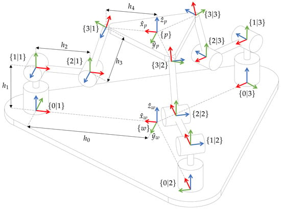
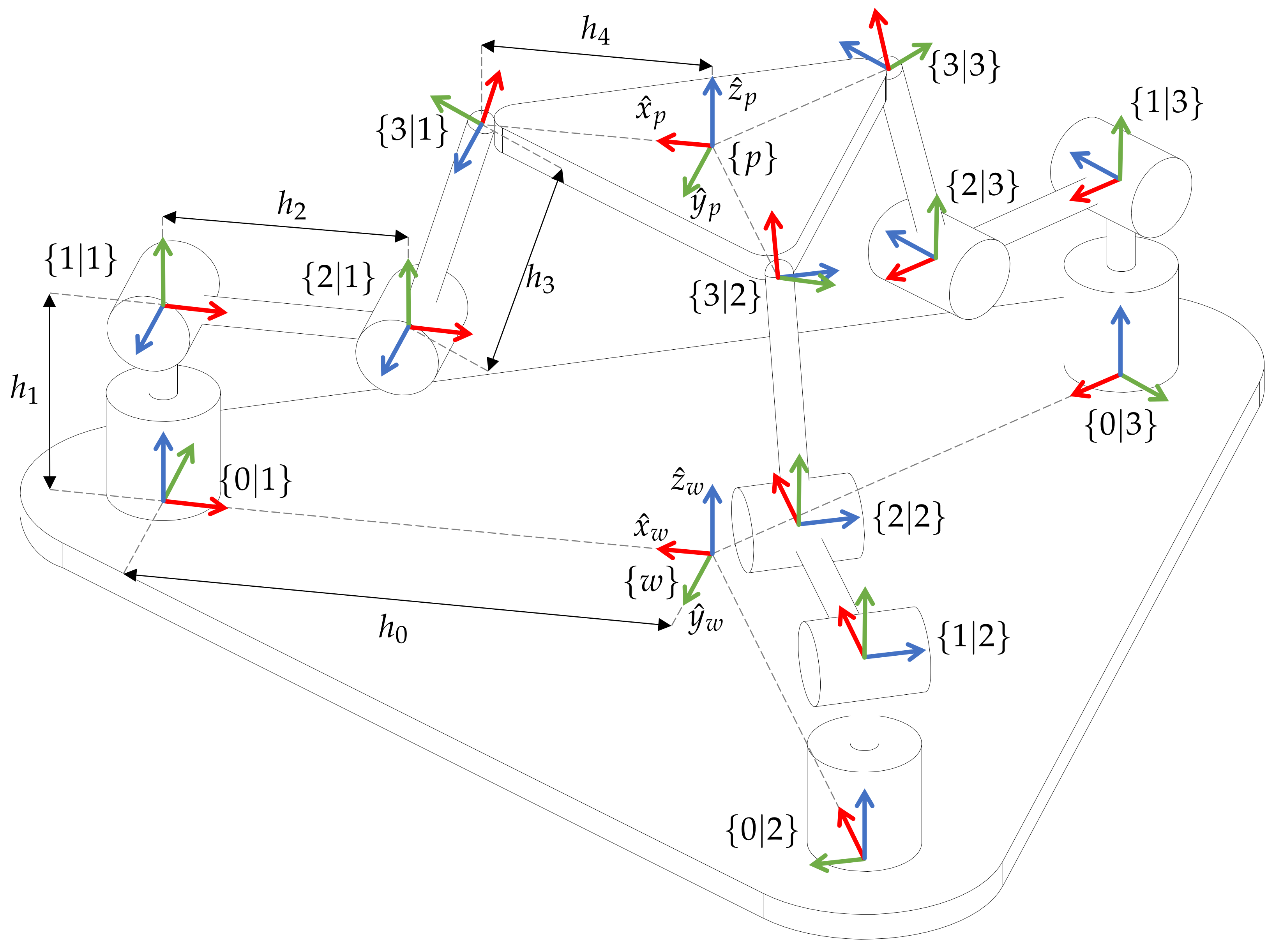
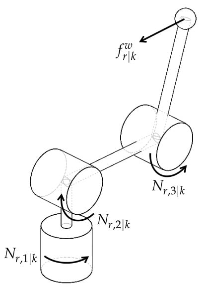
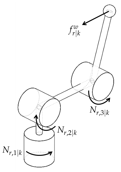
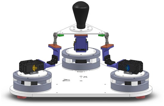
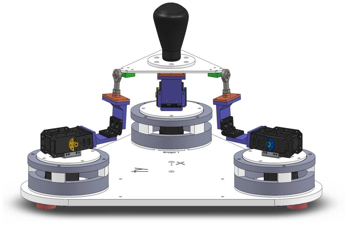
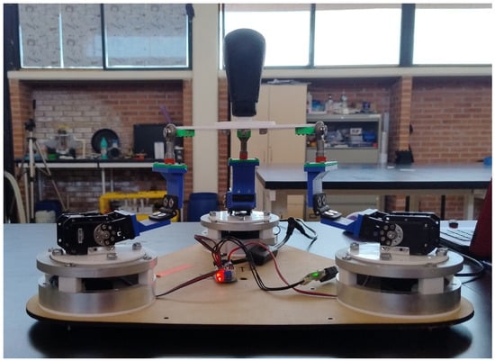
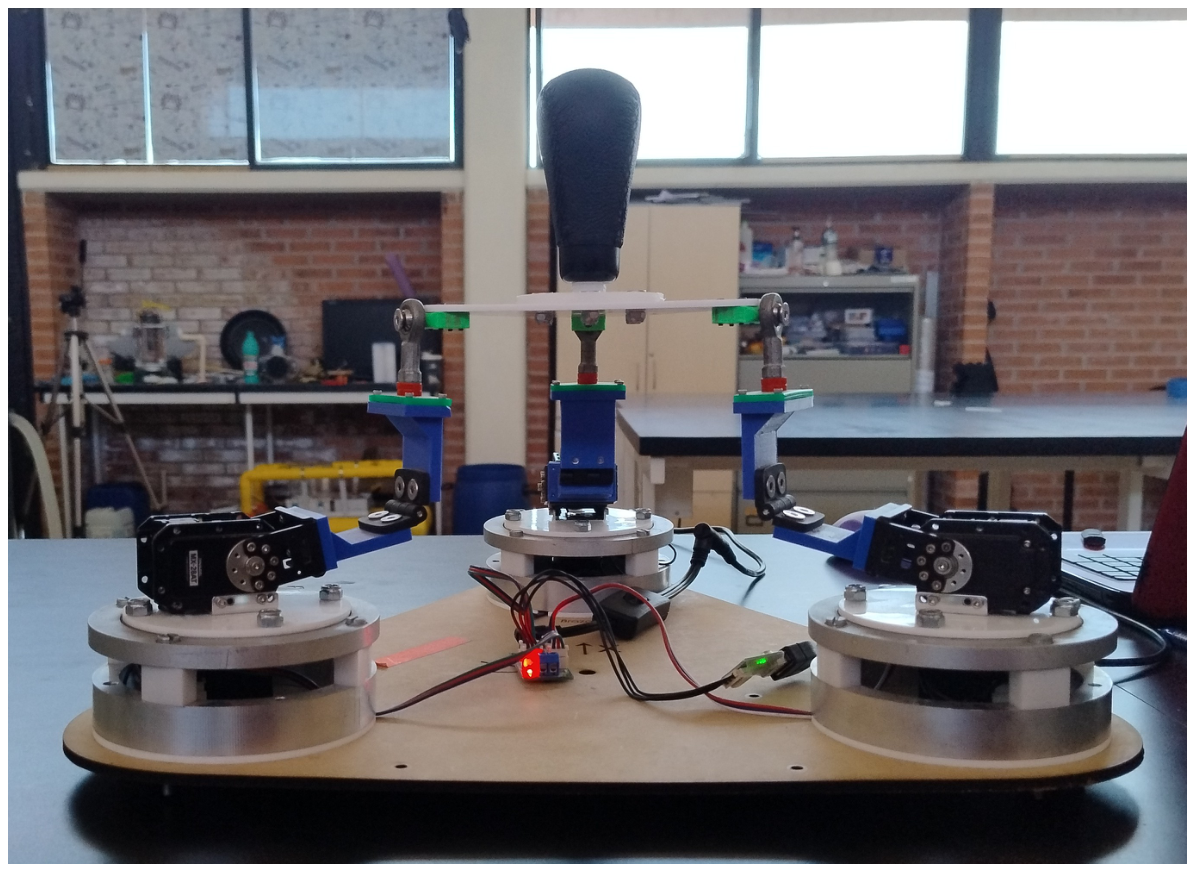
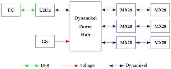
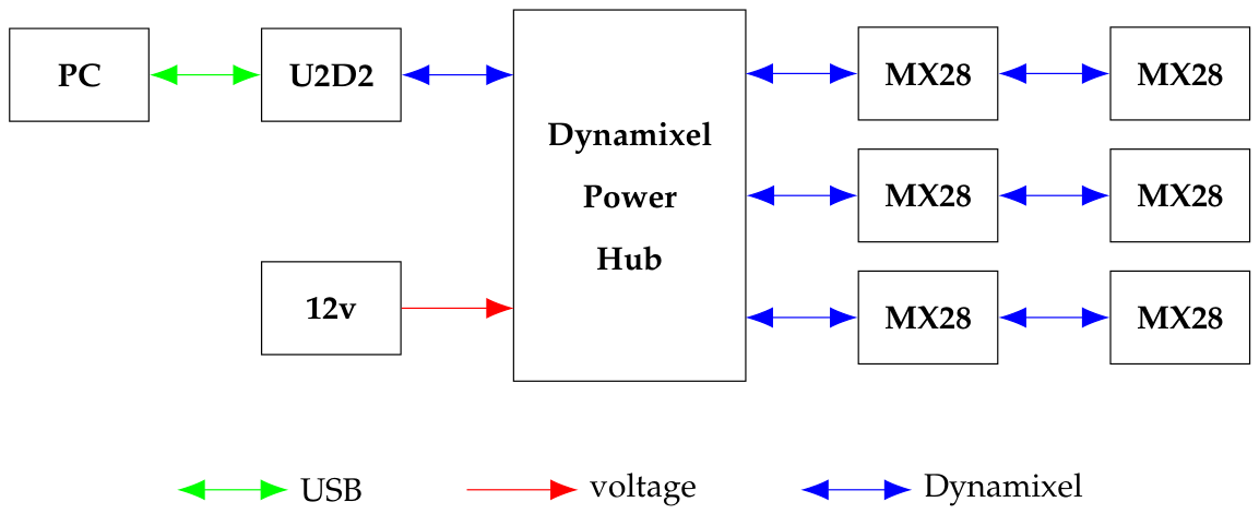
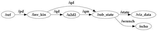
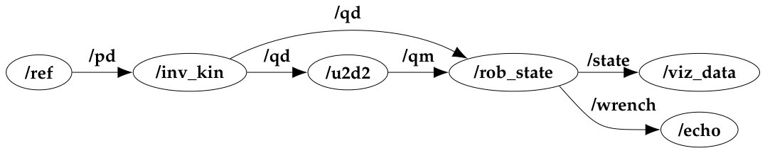
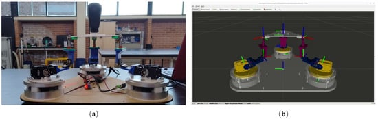
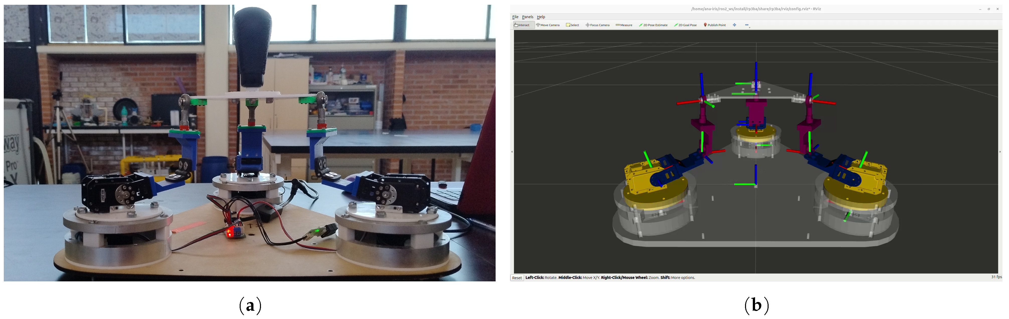
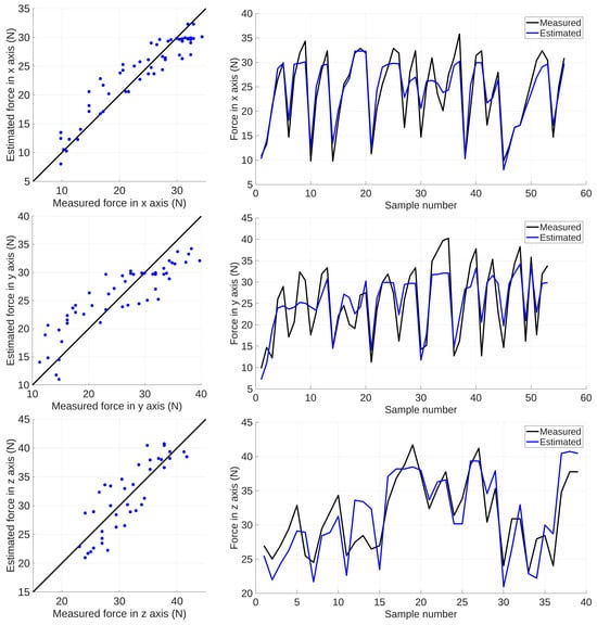
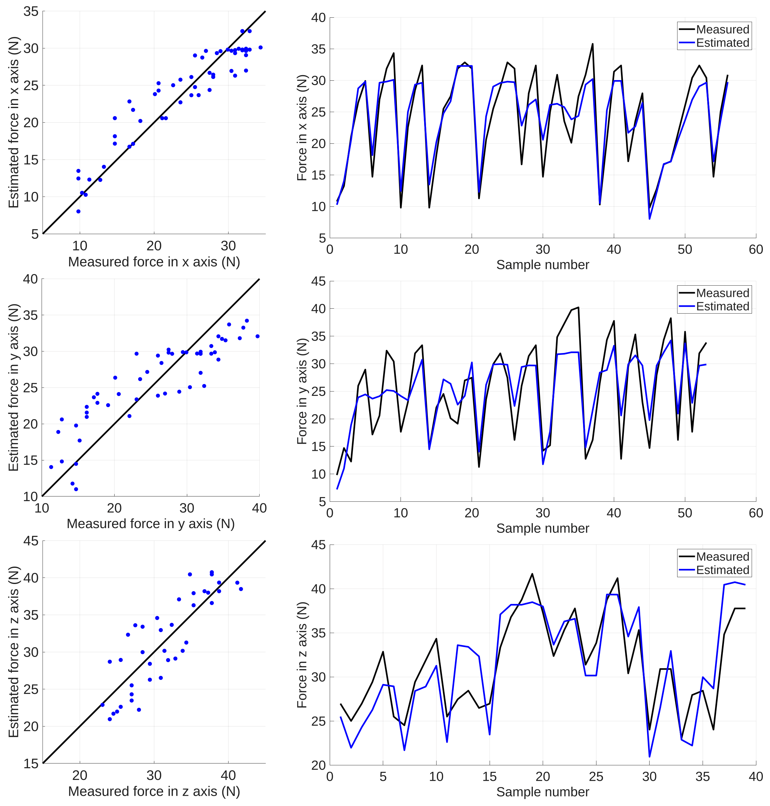
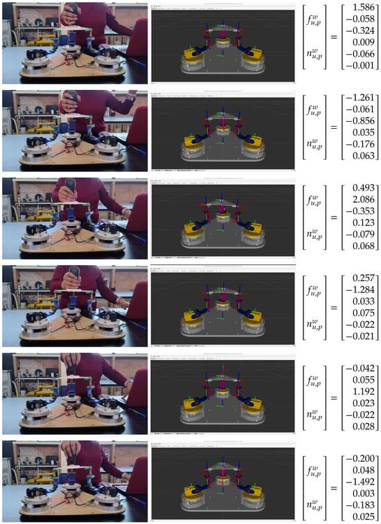
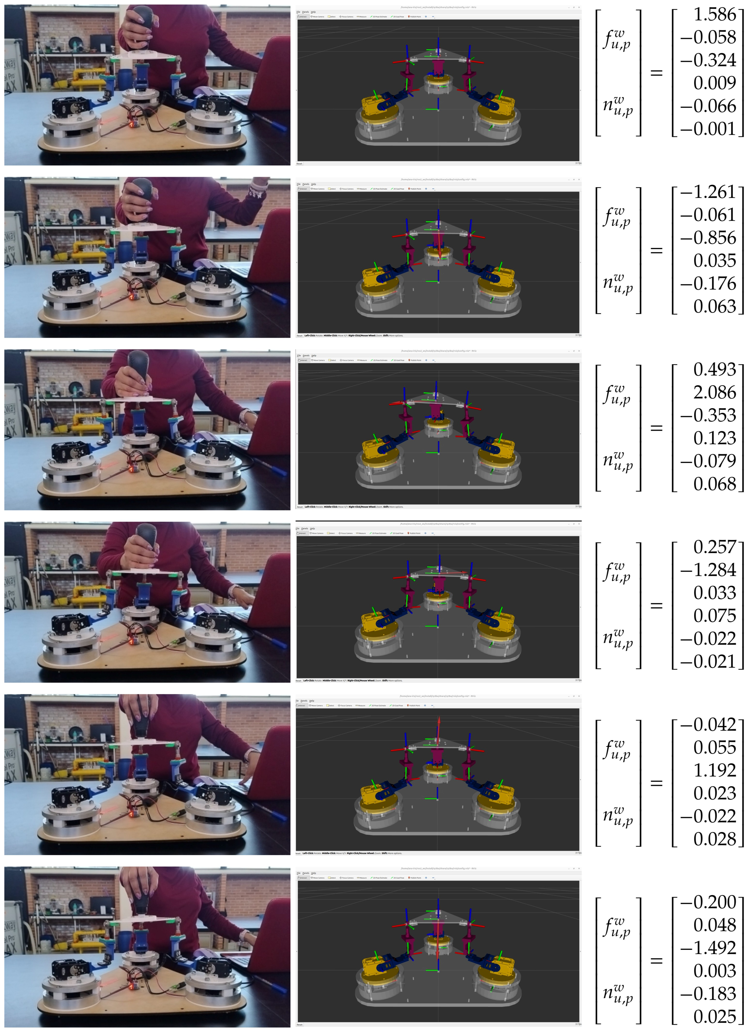
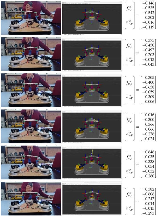
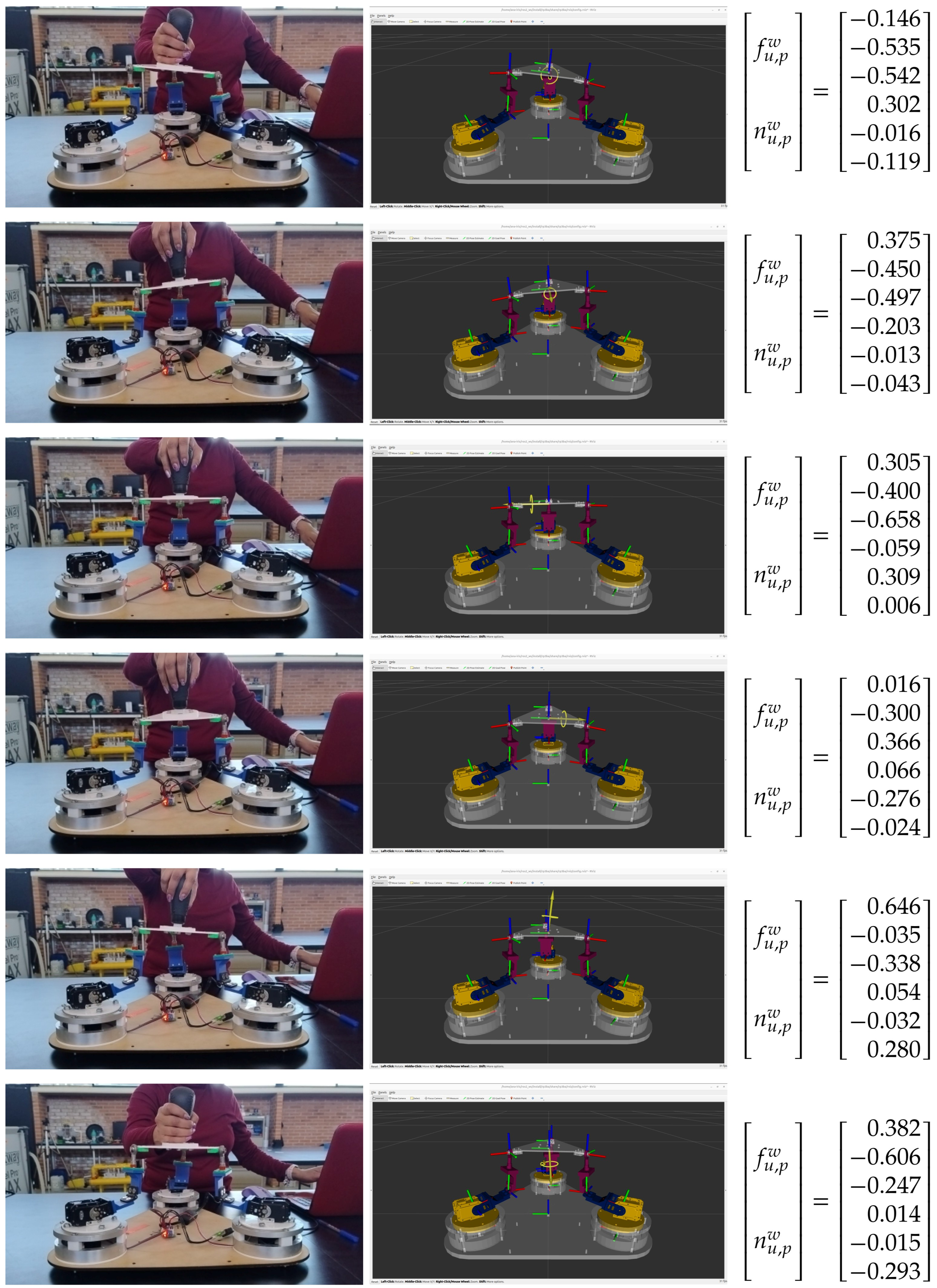
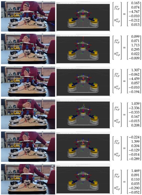
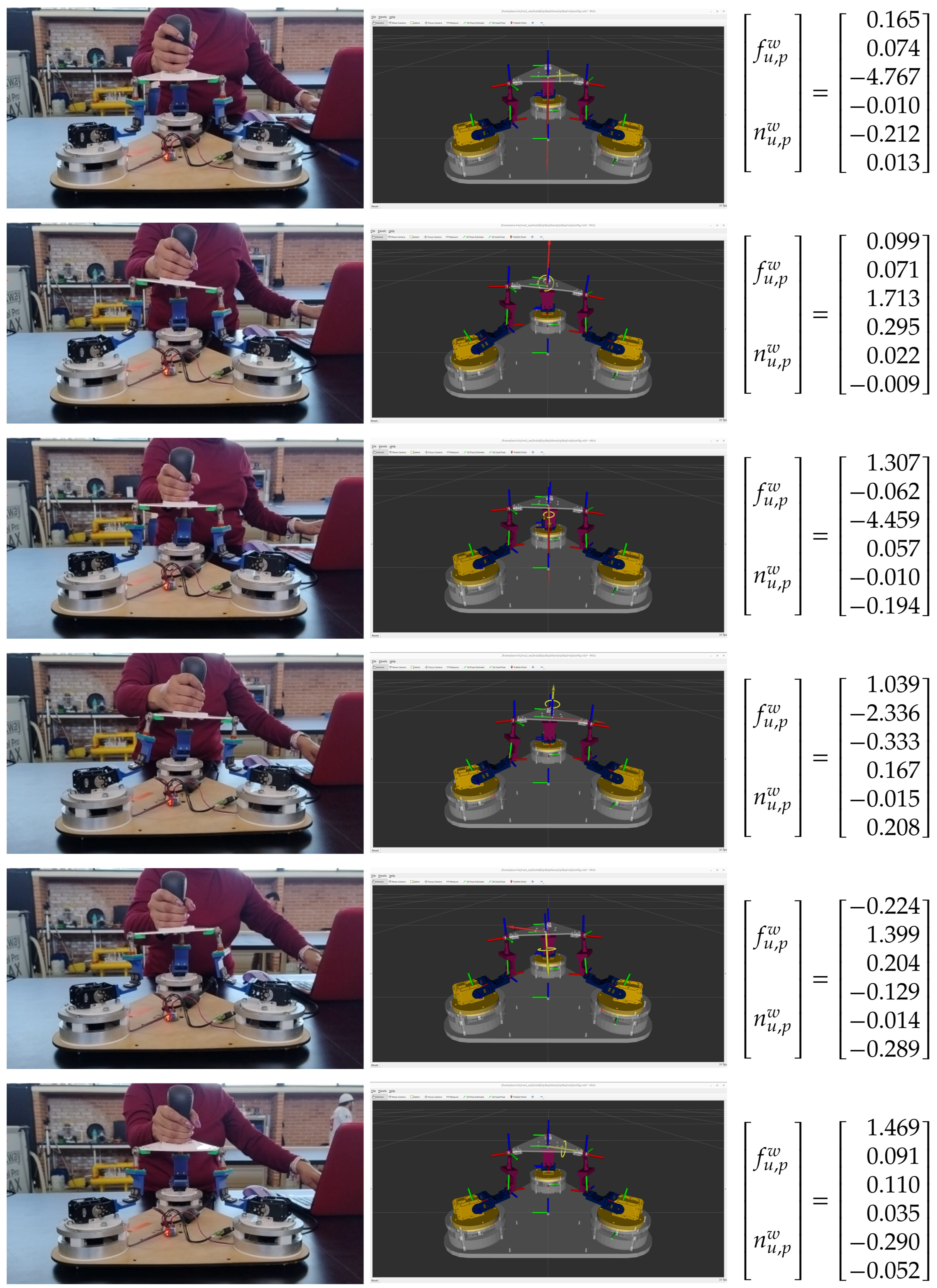
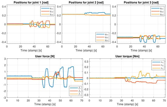
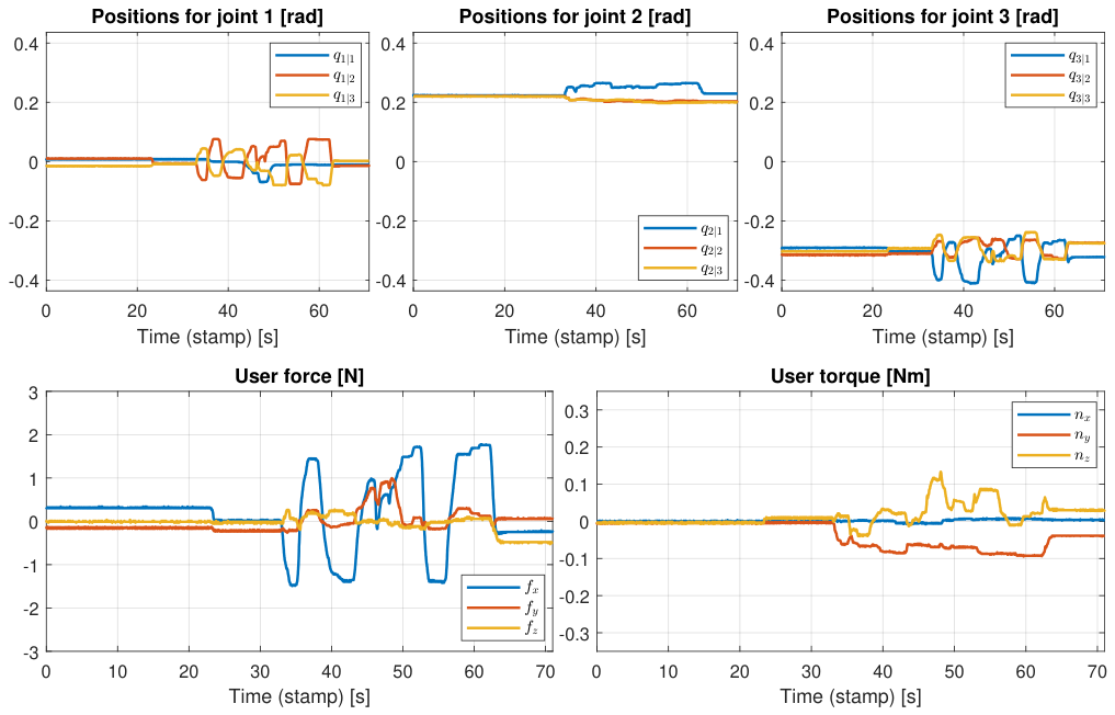
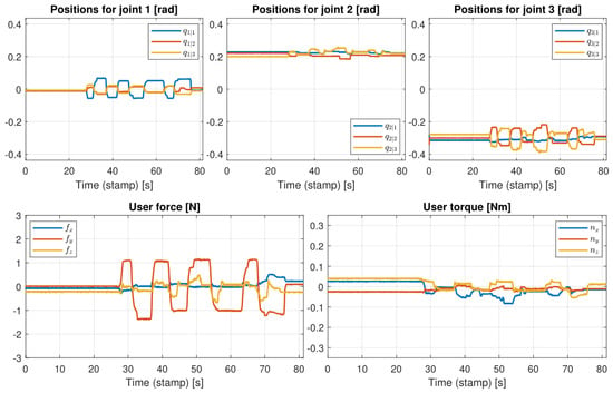
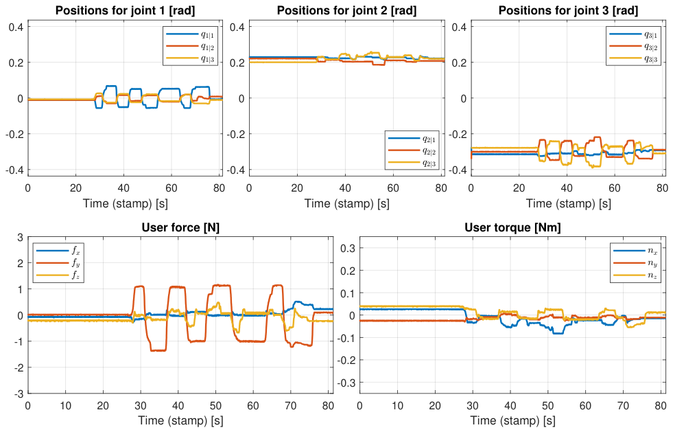
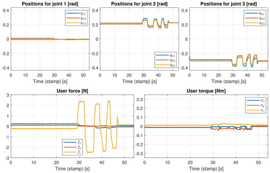
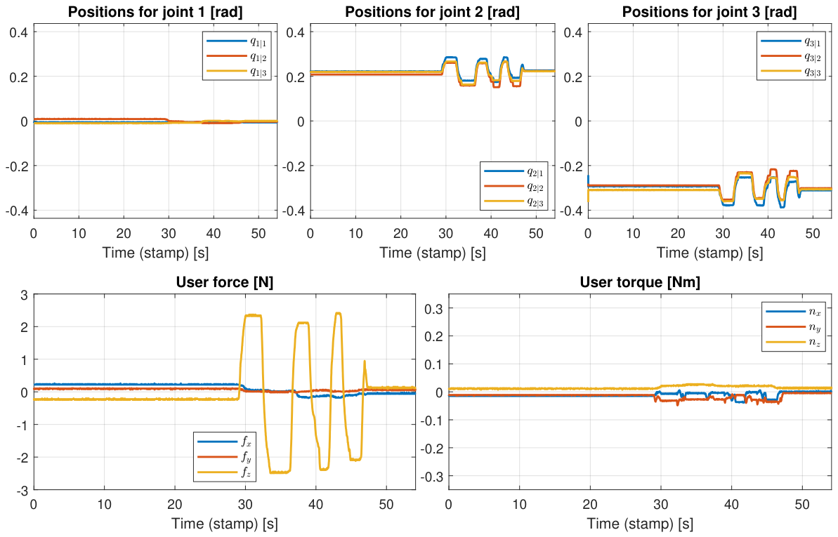
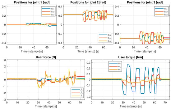
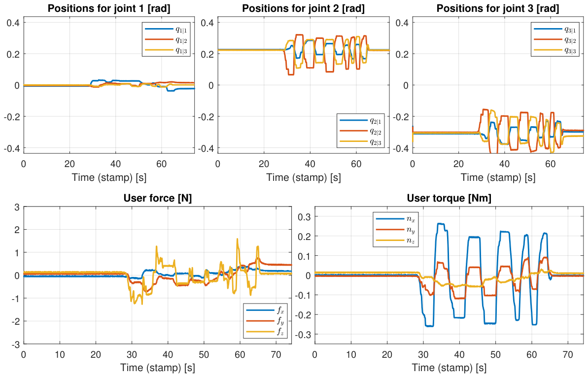
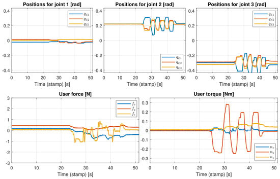
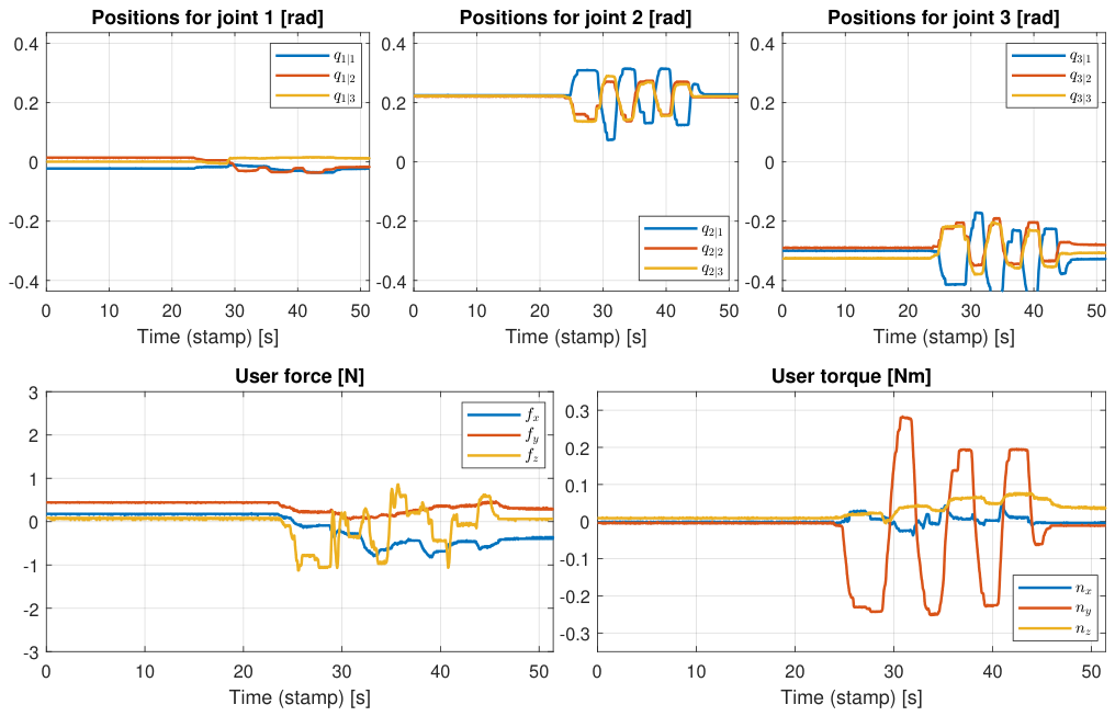
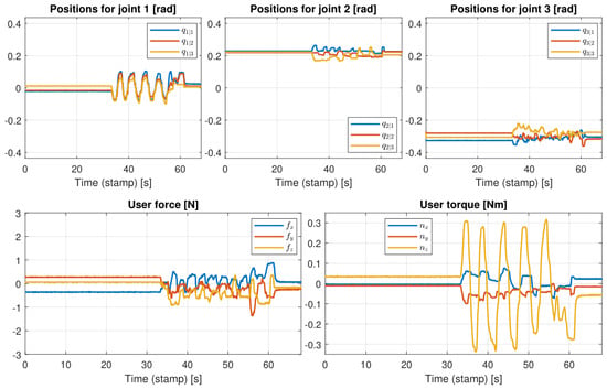
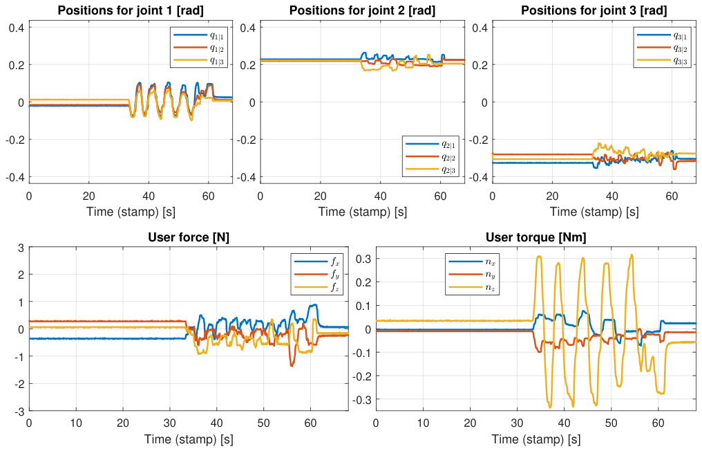

Disclaimer/Publisher’s Note: The statements, opinions and data contained in all publications are solely those of the individual author(s) and contributor(s) and not of MDPI and/or the editor(s). MDPI and/or the editor(s) disclaim responsibility for any injury to people or property resulting from any ideas, methods, instructions or products referred to in the content. |
© 2026 by the authors. Licensee MDPI, Basel, Switzerland. This article is an open access article distributed under the terms and conditions of the Creative Commons Attribution (CC BY) license.