


Abstract
This paper presents a numerical and energy-based assessment of a rapid-response linkage mechanism intended for an embedded child restraint seat. It is modeled as a rapid-repositioning device that modifies the child–seat system’s kinematic configuration. A single-degree-of-freedom model under base excitation represents the child–seat interaction during a frontal impact. We compare the reference case without the mechanism with a mechanism-enabled case using equivalent impact pulses with the same velocity change. The rapid-response input is limited to a 15 mm displacement in 0.1 s, corresponding to the maximum mechanical travel of the guided-slider region. The comparison is based on relative displacement, transmitted force, and positive accumulated transmitted energy. We evaluate mechanical performance indices to quantify the mechanism’s effect. A sensitivity study examines pulse shape, equivalent stiffness, damping ratio, child mass, activation delay, and partial mechanism displacement. Under the nominal half-sine pulse, the mechanism-enabled case reduces the maximum relative displacement by 0.99%, the maximum transmitted force by 0.99%, and the positive accumulated transmitted energy by 1.59%. The results are preliminary mechanical indicators, not injury criteria or regulatory validation. The proposed framework provides a design tool for evaluating rapid-response mechanisms before experimental and biomechanical testing.
1. Introduction
Child-occupant protection is a relevant vehicle-safety issue because children differ from adults in anthropometry, restraint needs, and dynamic response [1,2,3]. Child restraint systems (CRSs) improve child positioning, belt fit, load distribution, and occupant retention during vehicle travel and crash events [4,5,6,7]. However, their effectiveness depends on correct selection, installation, adjustment, belt routing, and compatibility with the vehicle seat; misuse remains a frequent source of performance degradation [6,7,8,9]. Integrated and embedded CRS concepts matter because they reduce dependence on removable devices and improve compatibility with rear-seat architecture. In these systems, the vehicle seat incorporates child-restraint functionality. However, this solution requires a compact mechanism that remains stored during normal use and generates the required child-seat configuration when activated.
A rapid-response mechanism can add function by producing a short repositioning motion early in a dynamic event. This motion does not absorb global crash energy, since the impact energy is much larger than the work delivered by a small actuator. Instead, the mechanism modifies the child–seat system’s early kinematic condition. Related vehicle-seat dynamics studies show that passive, semi-active, and mechatronic suspension concepts can modify a seat’s mechanical response. Ning et al. developed an electromagnetic variable-inertance device for heavy-duty vehicle seat suspension and demonstrated its application to vibration attenuation. Qiu et al. investigated a mechatronic inerter integrated into a vehicle seat suspension to improve vibration-isolation performance. More recently, Zhang et al. proposed an inerter–spring–damper seat suspension for commercial vehicles, combined with sky-hook control. These studies are relevant because they show that mechanical and mechatronic elements can intentionally modify seat dynamics. However, their main objective is road-vibration isolation and ride comfort. In contrast, the present work focuses on the early mechanical response of an embedded child restraint mechanism under equivalent frontal-impact inputs. Therefore, these studies are considered related seat-dynamic background rather than direct crash-protection validation [10,11,12].
Numerical modeling provides a practical basis for preliminary vehicle-safety assessment. Researchers have used lumped-parameter and finite-element approaches to study crash response and occupant–restraint dynamics [13,14,15,16,17,18,19], while CRS-specific models have been applied under static and dynamic conditions [14,20]. However, biomechanical and regulatory validation requires instrumented child dummies, controlled dynamic tests, restraint-load measurements, and standardized impact instrumentation [21,22,23,24,25]. Previous studies have used numerical simulations to evaluate child restraint systems in frontal and rollover crash scenarios, showing that restraint design and occupant positioning critically affect child injury risk and overall protection. In addition, we developed biomechanically representative neck models to improve assessment of head and neck injuries during impact events. Although these contributions have enhanced the understanding of child-occupant safety and injury mechanisms, they primarily focus on evaluating crash outcomes.
In contrast, this study investigates a rapid-response embedded restraint mechanism designed to modify the early dynamic behavior of the child–seat system, offering a proactive approach to improving occupant protection [26,27,28]. This paper extends that work by evaluating the same mechanism from a dynamic and energy-based perspective. The focus is not on mechanism synthesis, but on the mechanical effect of its rapid-response input on an equivalent child–seat dynamic model.
This paper’s main contribution is a numerical and energy-based framework for evaluating the mechanical effect of a rapid-response linkage mechanism before experimental and biomechanical validation. The specific contributions are: (i) formulation of an equivalent child–seat dynamic model under base excitation; (ii) representation of the rapid-response mechanism as an early prescribed kinematic input; (iii) comparison of baseline and mechanism-enabled cases under equivalent impact pulses; (iv) definition of mechanical performance indicators based on relative displacement, transmitted force, and positive accumulated transmitted energy; and (v) sensitivity analysis of pulse shape, child mass, equivalent stiffness, damping ratio, activation delay, and partial mechanism displacement.
The paper is organized as follows. Section 2 presents the materials and methods. Section 3 presents the numerical results. Section 4 discusses the mechanical interpretation, sensitivity effects, and model limitations. Section 5 presents the conclusions, the future validation path, and the model’s limitations.
2. Materials and Methods
This section presents the numerical methodology used to evaluate the rapid-response linkage mechanism in an embedded child restraint seat. The study focuses on the mechanism’s mechanical effect during the early stage of a frontal-impact event. This paper excludes experimental validation with instrumented child dummies, belt-load measurements, and regulatory injury criteria; CRS testing standards and impact-test instrumentation procedures should address these [21,22,23].
The methodology comprises eight stages: (i) definition of the embedded CRS concept; (ii) description of the rapid-response linkage mechanism and slider-guide corridor; (iii) definition of the main geometric and actuation parameters; (iv) formulation of the frontal-impact energy framework; (v) formulation of the reduced-order child–seat dynamic model; (vi) definition of the equivalent impact pulses and simulation cases; (vii) definition of the mechanical performance indicators and sensitivity analysis; and (viii) numerical implementation. The mechanism is not treated as a global crash-energy absorber. Its actuator work is small compared with the energy involved in a frontal vehicle impact. Therefore, the mechanism can be interpreted as a rapid-repositioning device. Its function is to modify the child–seat system’s early kinematic condition.
The results from this methodology are preliminary mechanical indicators. They are not injury criteria and do not represent regulatory validation. A complete validation would require experimental testing with an instrumented child dummy, seat-belt interaction, anchorage loads, and regulated dynamic test procedures.
2.1. Design Concept of the Embedded Child Restraint Seat
The embedded CRS is conceived as a child-seat function integrated into a passenger vehicle’s rear-seat architecture. During normal passenger use, the mechanism remains stored inside the seat structure. When the child-restraint function is required, the mechanism deploys to create seat and backrest support regions for the child.
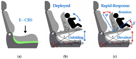
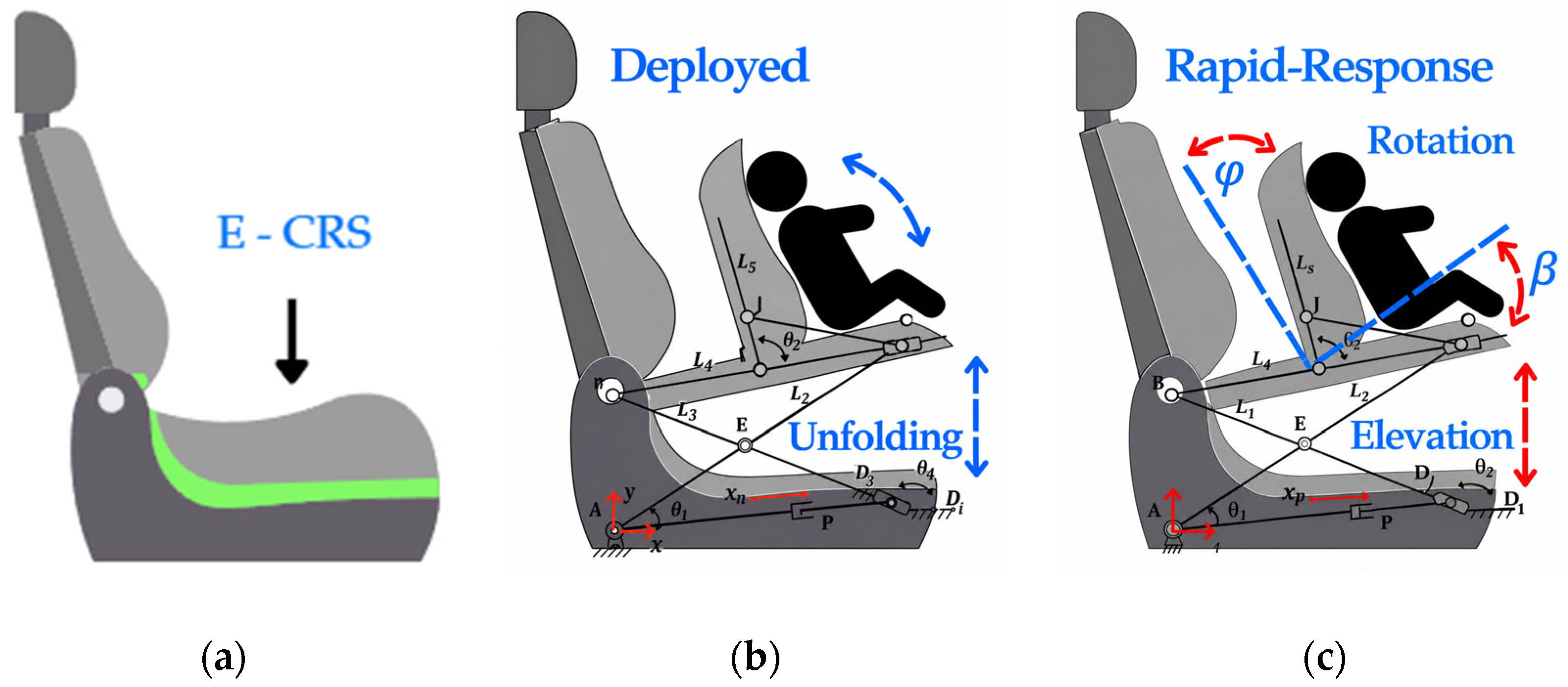
The concept has three main configurations, as shown in Figure 1: stored, deployed, and rapid-response. The stored configuration corresponds to normal rear-seat use. The deployed configuration corresponds to child-seat use. The rapid-response configuration starts from the deployed state and adds a short lifting and backrest angular repositioning motion during the early stage of a dynamic event.
Figure 1.
Design concept of the embedded child restraint seat: (a) stored configuration inside the rear seat; (b) deployed child-seat configuration; and (c) rapid-response configuration with lifting and backrest angular repositioning.
In this paper, we analyze the embedded CRS at the mechanism and equivalent dynamic-model levels. This study excludes complete CRS validation, including child dummy response, belt routing, anchorage loads, contact interaction, and regulatory injury criteria.
2.2. Rapid-Response Linkage Mechanism
The rapid-response linkage mechanism is the mechanical core of the embedded child restraint seat evaluated in this paper. Its development builds on prior work on integrated and powered CRS mechanisms, including the integrated CRS concept reported in EuCoMeS 2024 [29], the powered mechanism-based CRS design published in [20], and the performance characterization of the linkage-based child seat presented at MEDER 2026 [30]. In addition, the folding child restraint device was protected through an IMPI registration [31]. These previous works defined the system’s mechanical architecture and required motions.
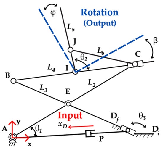
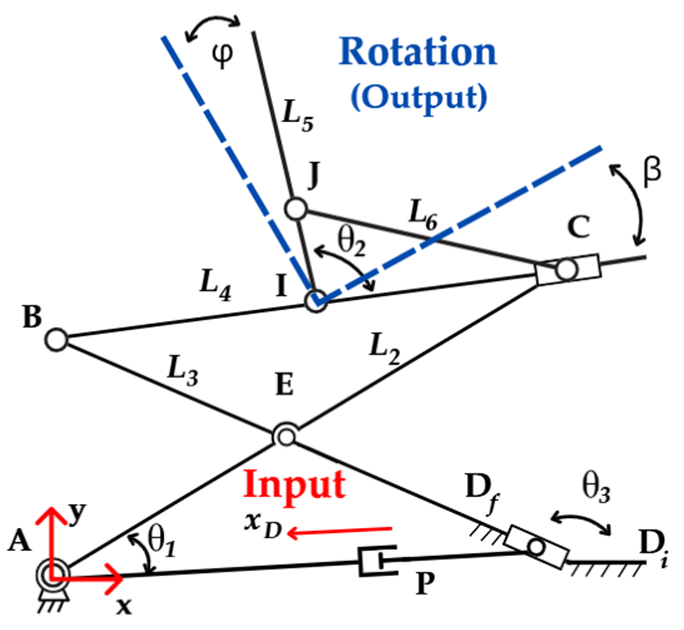
The mechanism comprises a scissor-type lifting subsystem and a guided slider-crank subsystem, as shown in Figure 2. The first subsystem provides the lifting motion of the seat support region, while the second subsystem controls the angular repositioning of the backrest. Both subsystems are driven by a single linear actuator applied at point P, which is suitable for an embedded seat application because of the limited available space.
Figure 2.
Kinematic design of the rapid-response linkage mechanism showing the actuator input at point P. With the slider-guide corridor at point D, the main links are L2, L3, L4, L5, and L6, and the angular repositioning of the backrest output link is L5.
The slider-guide corridor at point D constrains the motion of the slider-crank subsystem and defines the relation between actuator displacement, seat lifting, and backrest rotation. The backrest link L5 is the main output link because its angular displacement represents rapid repositioning of the backrest region.
In the nominal rapid-response condition, the guided displacement is limited to 15 mm. This displacement is applied in 0.1 s and produces an approximate angular repositioning of 20° in L5. This condition defines the maximum rapid-response motion considered in the numerical model. We treat the planar kinematics of the linkage mechanism separately from the reduced-order child–seat dynamic model. We previously performed a CAD-based motion analysis using the mechanism’s actual linkage geometry and joint constraints [20]. Starting from the deployed configuration, the analysis showed that a 15 mm rapid-response displacement completed within 0.1 s produces an additional rotation of approximately 20° in the backrest output link L5. These mechanism-level kinematic results define the physical rapid-response condition subsequently introduced into the reduced-order dynamic model.
The mechanism is not intended to absorb the vehicle’s global impact energy. The actuator displacement and actuator work are small compared with the kinetic energy involved in a frontal impact. Therefore, the mechanism is interpreted as a rapid-repositioning device that modifies the relative motion between the child and the seat during the event’s early phase.
2.3. Geometric Parameters and Rapid-Response Condition
The rapid-response condition is defined by the guided-slider displacement at point D and the resulting angular motion of the backrest output link L5. The maximum guided displacement is dD = 15 mm, which corresponds to the mechanical travel allowed by the slider-guide corridor. Smaller values are considered only as partial activation cases.
The target response time is defined as Tr = 0.1 s. Therefore, the nominal average velocity at the guided-slider region is calculated as
For dD = 0.015 m and Tr = 0.1 s, the nominal average velocity is vD = 0.150 m/s. In the same nominal rapid-response condition, this displacement produces an approximate angular repositioning of ΔθL5 ≈ 20° in the backrest output link.
The mechanical work delivered by the actuator during the nominal rapid-response motion is estimated as
where Fact is the reference actuator force and dD is the guided-slider displacement. For Fact = 490 N and dD = 0.015 m, the actuator work is Wact = 7.35 J. This value represents the mechanical work required to generate the rapid-repositioning motion and is not interpreted as global crash-energy absorption.
Wact = FactdD
The prescribed rapid-response displacement follows the half-cosine profile defined in Section 2.5. Therefore, although the average guided displacement velocity is vD = 0.150 m/s, the maximum prescribed velocity occurs at mid-stroke and is obtained from , giving for dD = 0.015 m and Tr = 0.1 s. For the reference actuator force Fact = 490 N, the corresponding mechanical work is Wact = 7.35 J, which gives an average mechanical power of approximately 73.5 W over the 0.1 s rapid-response interval. These values characterize the nominal actuator requirements considered in the present numerical study. Table 1 summarizes the main geometric and rapid-response parameters of the proposed mechanism.
Table 1.
Main geometric and rapid-response parameters of the design linkage mechanism.
The design development aims to evaluate whether a short, fast repositioning input can modify the relative displacement, transmitted force, and positive accumulated transmitted energy of a child–seat system under equivalent frontal-impact pulses.
2.4. Frontal-Impact Energy Framework
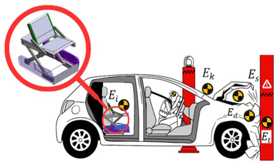
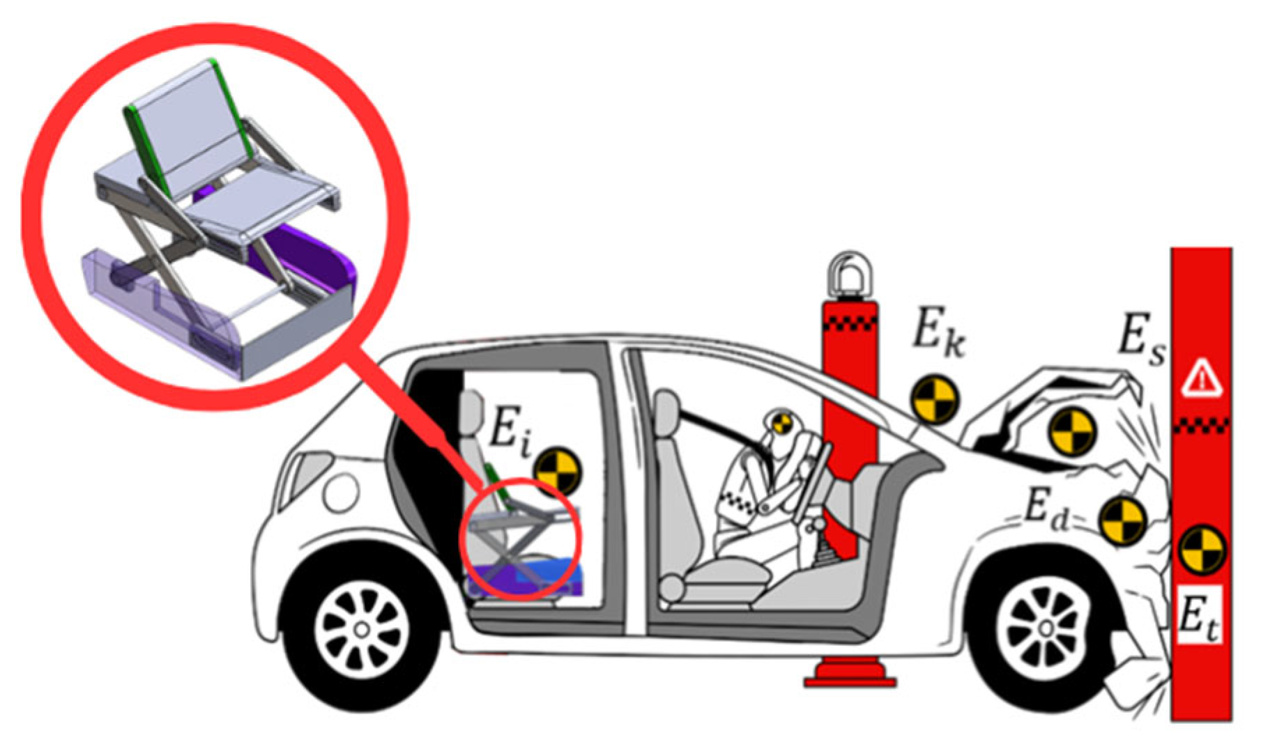
A frontal-impact energy framework compares the scale of the global vehicle kinetic energy, the child-related kinetic energy, and the mechanical work delivered by the actuator. This comparison clarifies the rapid-response mechanism’s mechanical role.
The initial kinetic energy of the vehicle is estimated as
where M is the vehicle mass and v0 is the initial vehicle velocity before impact. The child-related kinetic energy scale is estimated as
where m is the equivalent child mass; this value serves only as an energy-scale reference for the child mass moving at the initial vehicle velocity.
For the present study, the reference impact velocity is v0 = 40 km/h = 11.11 m/s, the vehicle mass is M = 1500 kg, and the equivalent child mass is m = 15 kg. From Equations (3) and (4), the vehicle kinetic energy is Ev = 92592.6 J, while the child-related kinetic energy scale is Ec = 925.9 J. The actuator work for the nominal rapid-response condition is Wact = 7.35 J, as defined in Equation (2).
The actuator work corresponds to approximately 0.79% of the child-related kinetic energy scale and 0.0079% of the vehicle kinetic energy. This difference confirms that the mechanism cannot be interpreted as a global crash-energy absorber. Instead, it provides a local, rapid-repositioning input that modifies the child–seat system’s early relative motion. Therefore, a reduction in transmitted force or positive accumulated transmitted energy in the dynamic model does not mean that the actuator absorbs the impact energy. Instead, it means the prescribed rapid-response motion modifies the child–seat system’s dynamic response under the same base excitation. Figure 3 summarizes this interpretation schematically.
Figure 3.
A scheme for frontal-impact energy framework with global vehicle kinetic energy, child-related kinetic energy scale, and actuator mechanical work used for rapid repositioning.
2.5. Child–Seat Dynamic Model
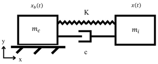
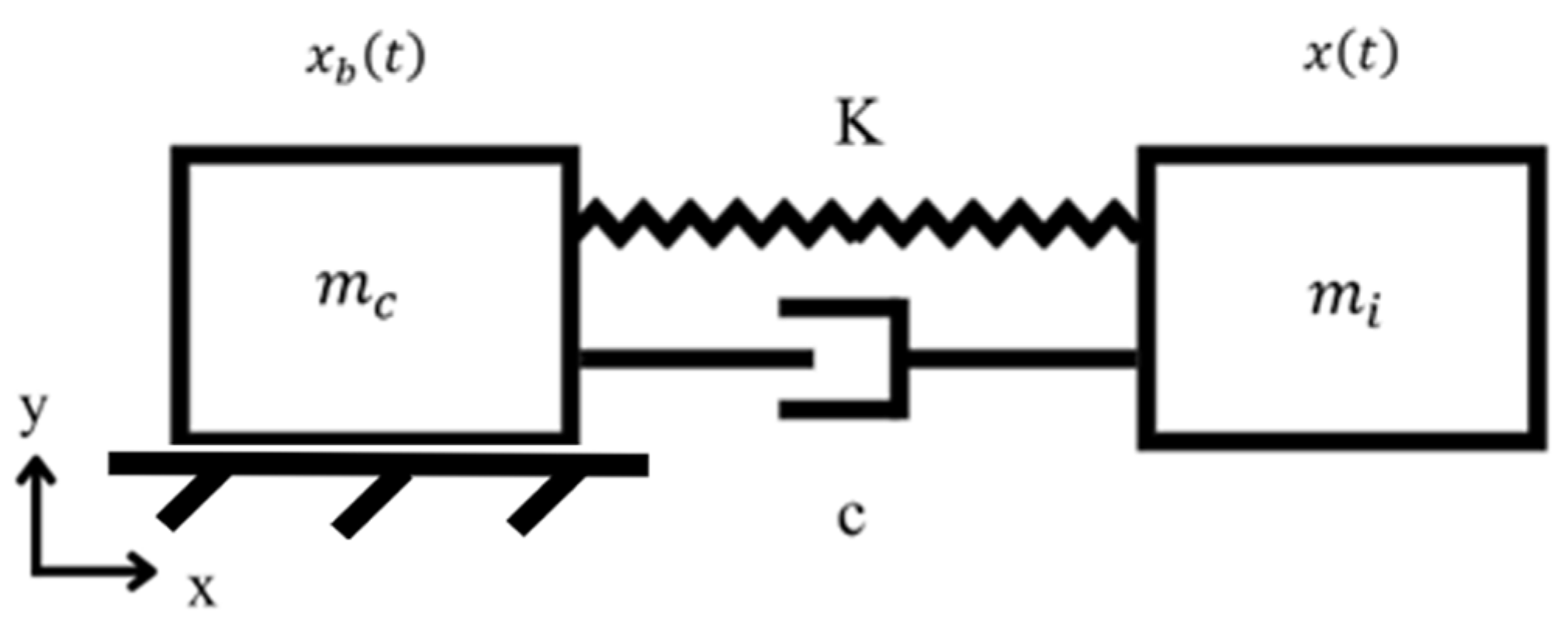
A single-degree-of-freedom model evaluates the mechanical effect of the rapid-response mechanism, as shown in Figure 4. The equivalent stiffness and damping are reduced-order parameters and do not correspond to individual physical components. The equivalent stiffness represents the combined compliance of the seat structure, backrest support, foam, restraint path, and contact interfaces. In contrast, the damping term represents the combined dissipative effects associated with material damping, foam deformation, restraint interaction, contact, and friction. The linear mass–spring–damper representation follows the standard formulation for base-excited lumped-parameter systems [16,17,19]. We use it here as an early-stage comparative model rather than a complete nonlinear representation of the CRS. For the nominal case, k = 5 × 10⁵ N/m and ζ = 0.15 are used. With m = 15 kg, Equation (7) gives c = 821.58 N s/m. These values are reference parameters for the reduced-order model and were not obtained from direct experimental identification of a specific CRS. The model is not intended to reproduce the complete biomechanical response of a seated child. It evaluates how a rapid-repositioning input modifies the relative displacement, transmitted force, and positive accumulated transmitted energy of the child–seat system.
Figure 4.
Child–seat dynamic model under base excitation. The model represents the child–seat interaction through an equivalent mass, stiffness, and damping system.
The 1-DOF formulation represents only the dominant relative response of the equivalent child–seat system in the principal impact direction. It is not intended to reproduce the planar multi-link kinematics of the mechanism itself. The mechanism motion is defined independently from the CAD-based kinematic analysis described in Section 2.2 and is introduced into the present formulation as a prescribed seat-side kinematic input. This separation provides a compact model for comparing the baseline and mechanism-enabled responses and for performing the parametric sensitivity analyses considered in this study.
Accordingly, the reduced-order model does not represent vertical seat motion, coupled backrest rotation, individual child-body segments, belt slack and routing effects, contact transitions, joint clearances, or nonlinear material behavior. These effects require a higher-order multibody or finite-element representation and are outside the scope of the present preliminary numerical assessment.
The absolute displacement of the equivalent child mass is defined as x(t), and the base displacement imposed by the vehicle seat is defined as xb(t). The relative displacement is
y(t) = x(t) − xb(t)
For the baseline case without the rapid-response mechanism, the equation of motion under base excitation is
where m is the equivalent child mass, c is the equivalent damping coefficient, k is the equivalent stiffness, and is the base acceleration input. The equivalent damping coefficient is calculated as
where ζ is the damping ratio. The transmitted force between the equivalent child mass and the seat support is calculated from the model as
This force is used only as a mechanical indicator of load transmission through the equivalent stiffness–damping path. It is not equivalent to belt load, chest load, neck load, or any regulated injury-related force. The positive accumulated transmitted energy is calculated as
Since , the instantaneous product contains two contributions: the rate of change in recoverable spring energy, , and the viscous dissipation term, . Therefore, should not be interpreted as purely dissipated energy or as an energy-absorption metric. It is used here as a positive accumulated mechanical-interaction indicator for comparing the baseline and mechanism-enabled responses. For the reduced-order model, the mechanical energy balance includes the kinetic energy , the recoverable spring energy , and the cumulative damping dissipation . In the baseline case, the imposed base acceleration drives these contributions. In the mechanism-enabled case, the prescribed rapid-response input adds a work contribution through the modified base-side motion. The actuator mechanical work Wact = 7.35 J is reported separately as a mechanism-level reference and is not directly identified with . For the mechanism-enabled case, the rapid-response motion is introduced as a prescribed kinematic input ur(t). The effective seat-side displacement is written as
where η = 0.00587 is the reduced-order coupling coefficient used to map the prescribed slider displacement dD into the equivalent one-dimensional seat-side displacement, Δxeq = ηdD. For dD = 15 mm, Δxeq = 0.088 mm.
xs(t) = xb(t) + ηur(t)
ym(t) = x(t) − xs(t)
ym(t) = x(t) − xb(t) − ηur(t)
ym(t) = x(t) − xb(t) − ηur(t)
The corresponding equation of motion of the child seat becomes
This equation shows that the rapid-response mechanism modifies the dynamic input through an additional prescribed kinematic contribution. It does not mean that the actuator absorbs the impact energy. The rapid-response displacement is represented using a smooth half-cosine function:
where ta is the activation time, dD is the imposed rapid-response displacement, and Tr is the rapid-response time. For immediate activation, ta = 0. For delayed activation cases, ta is assigned values between 10 ms and 50 ms.
ur(t) = 0, t < ta
ur(t) = dD, t > ta + Tr
2.6. Equivalent Impact Pulses and Numerical Cases
Equivalent frontal-impact pulses are applied to the equivalent child–seat dynamic model to evaluate the influence of the acceleration-time profile. All pulses are defined with the same velocity change Δv and the same nominal duration Timp. Therefore, they are compared under the same global velocity-change condition, while their peak accelerations and acceleration-time histories remain different. They should not be interpreted as dynamically identical crash events. The velocity change is obtained from
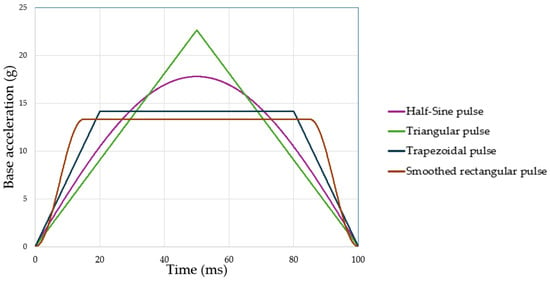
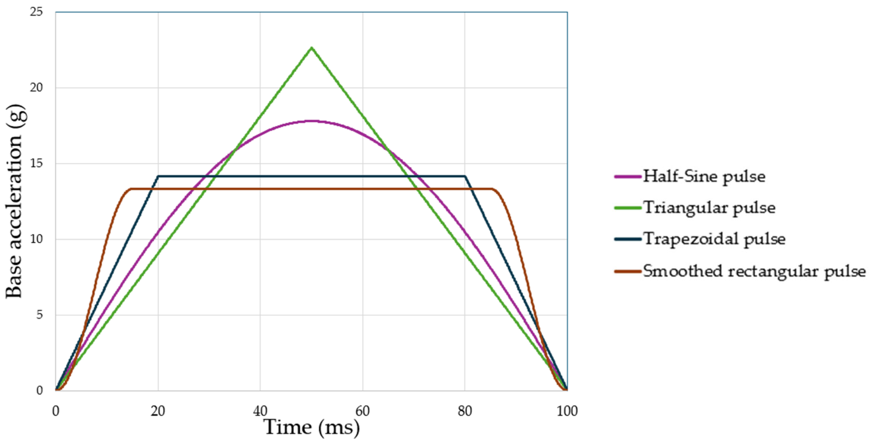
where ab(t) is the base acceleration input and Timp is the impact-pulse duration. In this study, the nominal velocity change is Δv = 11.11 m/s, corresponding to 40 km/h, and the nominal pulse duration is Timp = 0.1 s. We consider four equivalent pulse shapes: half-sine, triangular, trapezoidal, and smoothed rectangular. For Δv = 11.11 m/s and Timp = 0.1 s, the corresponding peak accelerations are approximately 17.8 g, 22.6 g, 14.2 g, and 13.3 g for the half-sine, triangular, trapezoidal, and smoothed rectangular pulses, respectively. We use these analytical profiles as representative short-duration frontal inputs for sensitivity analysis; they are not intended to reproduce a specific regulatory crash-pulse corridor. The half-sine pulse is defined as
where the amplitude is
For the triangular pulse, the acceleration is defined as
where
The trapezoidal pulse includes a linear rise, a constant plateau, and a linear decay. The rise time is tr = αTimp, with 0 < α < 0.5, and the pulse is expressed as
where the amplitude is
For the smoothed rectangular pulse, a normalized smooth function is used to avoid discontinuities at the beginning and end of the pulse:
where f(t) is a smooth window function with half-cosine transitions. The numerical cases comprise one baseline condition and seven mechanism-enabled conditions. The same base excitation ab(t) is applied in all cases, while the mechanism-enabled cases include a prescribed displacement ur(t) with dD = 5, 10, or 15 mm and activation delays from 0 to 50 ms. Table 2 summarizes the cases, and Figure 5 shows the equivalent impact pulses.
Table 2.
Numerical cases used for the baseline and mechanism-enabled simulations.
Figure 5.
Impulse-equivalent frontal-impact pulses with the same velocity change Δv = 11.11 m/s: as half-sine, triangular, trapezoidal, and smoothed rectangular acceleration profiles.
2.7. Mechanical Performance Indicators and Sensitivity Analysis
We evaluate the mechanical performance of the rapid-response mechanism by comparing the baseline case without the mechanism and the mechanism-enabled case. The comparison is based on three output variables: maximum relative displacement, maximum transmitted force, and positive accumulated transmitted energy. The maximum relative displacement is computed as
where y(t) is the relative displacement defined in Equation (5). The maximum transmitted force is computed as
where F(t) is the transmitted force defined in Equation (8). The final value of the positive accumulated transmitted energy is computed as
where tf is the final simulation time. We use three mechanical performance indicators to quantify the rapid-response mechanism’s effect. The relative displacement reduction index is defined as
ymax = max∣y(t)∣
Fmax = max∣F(t)∣
The transmitted-force reduction index is defined as
and the positive accumulated transmitted energy reduction index is defined as
where subscript A represents the baseline case and subscript B represents the mechanism-enabled case. A positive value indicates a reduction with respect to the baseline case. A value close to zero indicates a small mechanical effect, while a negative value indicates an increase in the corresponding response variable.
We perform a sensitivity analysis to evaluate how the main parameters affect the equivalent child–seat dynamic response. We evaluate child mass, equivalent stiffness, damping ratio, activation delay, and rapid-response displacement. Table 3 summarizes these parameters.
Table 3.
Sensitivity analysis parameters.
The equivalent masses m = 15, 22, and 30 kg represent progressively heavier child-occupant conditions. The nominal 15 kg case is close to the Q3 dummy mass specified in UN Regulation No. 129 [21], while 22 kg represents a heavier condition close to the Q6 dummy mass. The 30 kg case is included only as an upper sensitivity condition and does not represent a certified dummy category. These values therefore represent mass conditions for the sensitivity analysis, not certified occupant categories.
The nominal case is defined by m = 15 kg, k = 5 × 10⁵ N/m, ζ = 0.15, Timp = 0.1 s, dD = 15 mm, and Tr = 0.1 s. We calculate the damping coefficient from the selected damping ratio using Equation (7). For each case, we calculate the same output variables and reduction indices. This procedure allows comparison of the rapid-response mechanism’s effect under different mechanical conditions without interpreting the indicators as injury criteria or regulatory validation.
We use variations in mass, stiffness, damping ratio, activation timing, mechanism displacement, and impact-pulse shape in a deterministic parametric sensitivity assessment to examine the robustness of the predicted trends. Do not interpret them as a probabilistic uncertainty analysis or as statistical confidence intervals.
2.8. Numerical Implementation
We solved the governing equation of the baseline equivalent child–seat model numerically in the time domain using an explicit fourth-order Runge–Kutta (RK4) integration scheme implemented in MATLAB R2023a. A fixed time step of Δt = 1 × 10⁻⁴ s was used over a total simulation time of tf = 0.50 s. The initial relative displacement and velocity were set to zero, y(0) = 0 and . We used the same temporal discretization and initial conditions for all impact-pulse and sensitivity cases. The rapid-response contribution was evaluated using the prescribed kinematic input ur(t) and its time derivative according to the formulation described in Section 2.5. The positive accumulated transmitted energy was evaluated numerically using trapezoidal integration of the positive part of the instantaneous mechanical power .
3. Results
This section presents the numerical results obtained with the equivalent child–seat dynamic model. We compare the baseline case without the mechanism with the mechanism-enabled case using equivalent frontal-impact pulses with the same velocity change.
The results are organized by nominal response, pulse shape, activation delay, partial mechanism displacement, and sensitivity to child mass, equivalent stiffness, and damping ratio. In all cases, the reduction indices are calculated with respect to the corresponding baseline condition.
3.1. Baseline and Mechanism-Enabled Response
The nominal response is evaluated using the half-sine impact pulse with Δv = 11.11 m/s and Timp = 0.1 s. The mechanism-enabled case uses the nominal rapid-response condition, with dD = 15 mm, Tr = 0.1 s, and immediate activation. Table 4 summarizes the numerical comparison between the baseline and mechanism-enabled cases.
Table 4.
Nominal baseline and mechanism-enabled response.
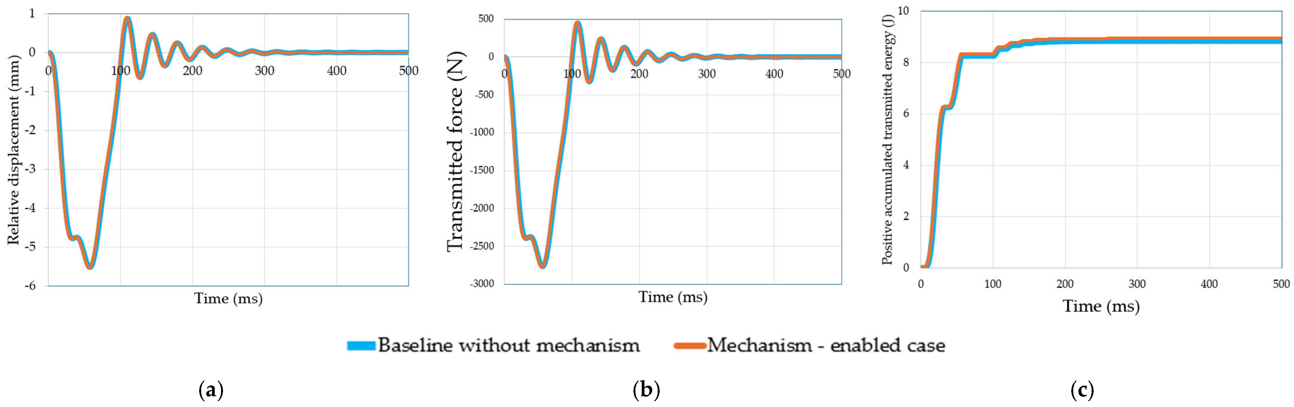
The results show a small but measurable reduction in the three mechanical response variables. The maximum relative displacement decreases from 5.417 mm to 5.363 mm, a reduction of about 0.99%. The maximum transmitted force decreases from 2714.82 N to 2687.92 N, while the positive accumulated transmitted energy decreases from 8.473 J to 8.338 J.
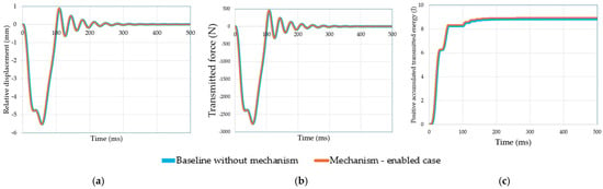
Figure 6 shows the computed nominal response in terms of relative displacement, transmitted force, and positive accumulated transmitted energy. The mechanism-enabled response follows the same general trend as the baseline case, but with slightly lower peak and accumulated values. This confirms that the rapid-response input modifies the child–seat model’s early mechanical response, although the effect remains moderate.
Figure 6.
Computed response for the nominal baseline and mechanism-enabled cases: (a) relative displacement; (b) transmitted force; and (c) positive accumulated transmitted energy.
Figure 6b shows the transmitted-force response. Because it is calculated from the equivalent stiffness–damping path, it decreases in the same way as the relative displacement response. The mechanism-enabled case produces a slightly lower force peak than the baseline case. The positive accumulated transmitted energy is shown in Figure 6c. The mechanism-enabled case presents a slightly lower final accumulated value than the baseline case. The results confirm that the proposed rapid-response mechanism can modify the child–seat system’s mechanical response. However, the nominal case reduction is limited. Therefore, interpret the mechanism effect with caution. The result does not represent injury reduction, regulatory validation, or full CRS performance. It only indicates that the imposed rapid-response input produces a measurable change in relative displacement, transmitted force, and positive accumulated transmitted energy under the selected numerical conditions.
3.2. Effect of Impac-Pulse Shape
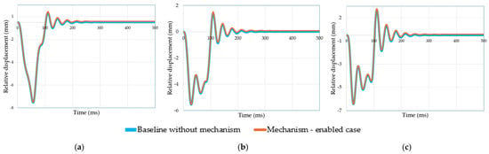
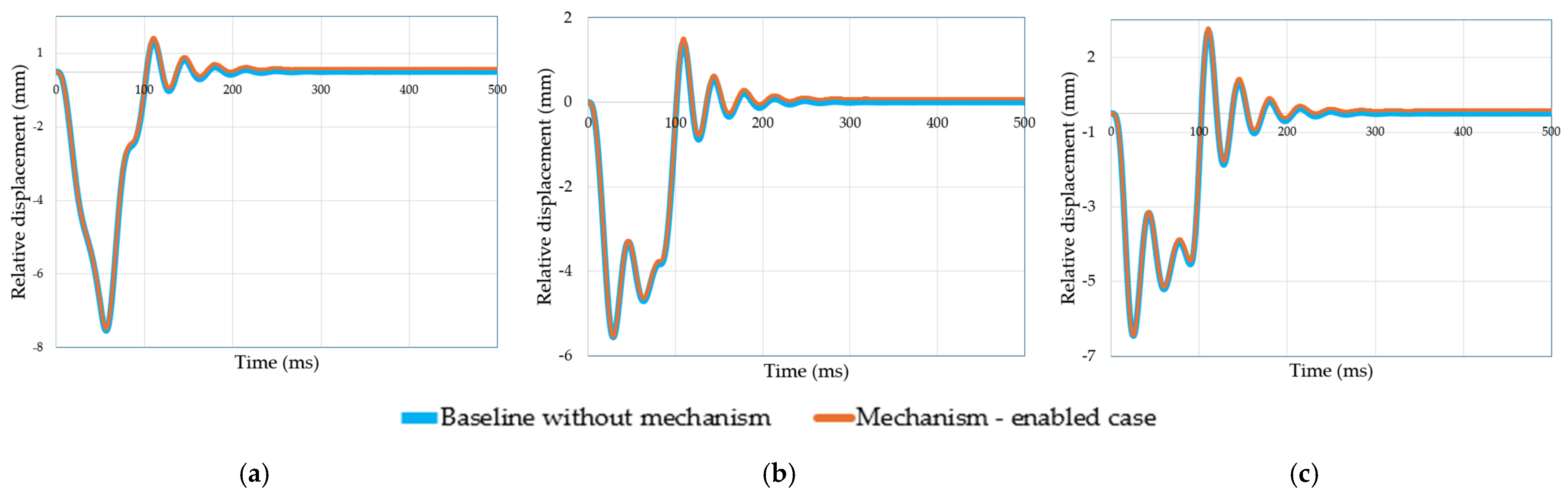
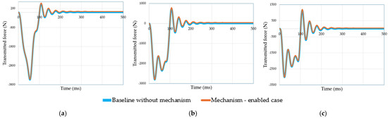
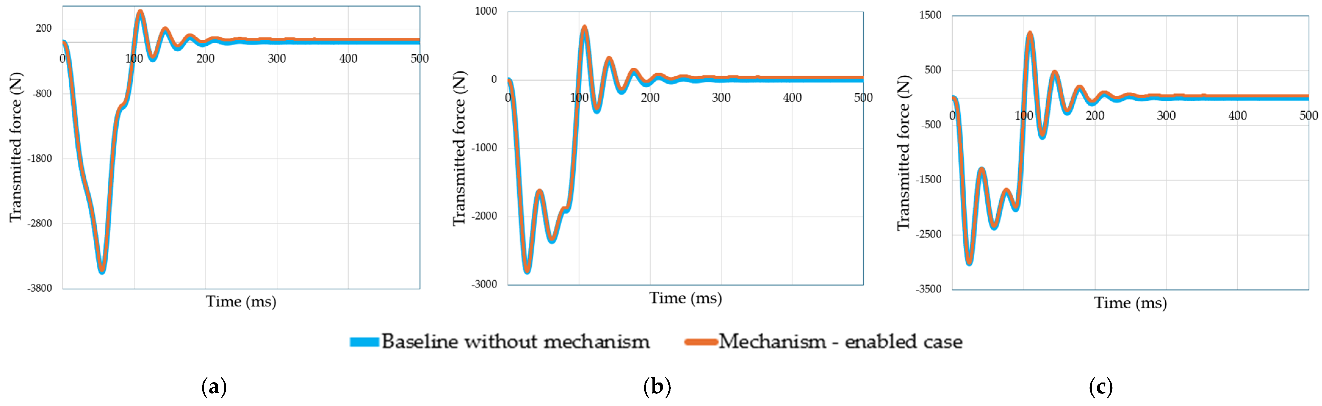
The effect of impact-pulse shape is evaluated using four equivalent frontal acceleration profiles: half-sine, triangular, trapezoidal, and smoothed rectangular pulses. All pulses have the same velocity change, Δv = 11.11 m/s, and the same nominal duration, Timp = 0.1 s. Therefore, we evaluate the differences in response under the same velocity change and duration conditions, and they are primarily associated with differences in the acceleration-time profile and peak acceleration.
Figure 7, Figure 8 and Figure 9 show the computed response for the different pulse shapes in terms of relative displacement, transmitted force, and positive accumulated transmitted energy. We used the same equivalent mass, stiffness, damping ratio, and rapid-response condition in all cases.
Figure 7.
Effect of impact-pulse shape on the relative displacement response: (a) triangular pulse; (b) trapezoidal pulse; and (c) smoothed rectangular pulse.
Figure 8.
Effect of impact-pulse shape on the transmitted-force response: (a) triangular pulse; (b) trapezoidal pulse; and (c) smoothed rectangular pulse.
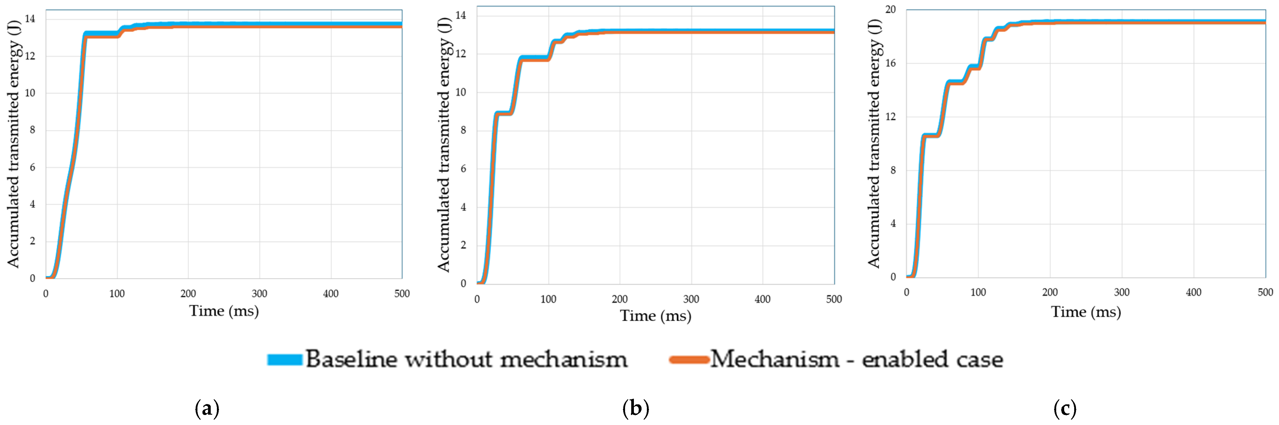
Figure 9.
Effect of impact-pulse shape on the positive accumulated transmitted energy: (a) triangular pulse; (b) trapezoidal pulse; and (c) smoothed rectangular pulse.
Table 5 summarizes the numerical indicators obtained for each pulse shape. The half-sine pulse gives the largest reduction in the nominal case, with Ry = 0.99%, RF = 0.99%, and RE = 1.59%. The triangular, trapezoidal, and smoothed rectangular pulses also show reductions, but to a lesser extent.
Table 5.
Effect of impact-pulse shape on the mechanical performance indicators.
This confirms that the response depends on the acceleration-time profile, even when the same velocity change is preserved.
3.3. Effect of Activation Delay
The effect of activation delay is evaluated by shifting the beginning of the rapid-response input ur(t). The baseline case is kept unchanged, while the mechanism-enabled cases are calculated with ta = 0, 10, 20, 30, 50 ms. In all cases, the same half-sine frontal-impact pulse is used, with Δv = 11.11 m/s and Timp = 0.1 s.
The case ta = 0 is used only as an ideal numerical reference corresponding to activation at the beginning of the imposed acceleration pulse. It should not be interpreted as a realistic crash-detection and control latency. The cases ta = 10, 20, 30, and 50 ms are parametric delay conditions introduced to quantify the mechanism’s sensitivity to progressively later activation. These values are not measurements from a specific sensing or control system.
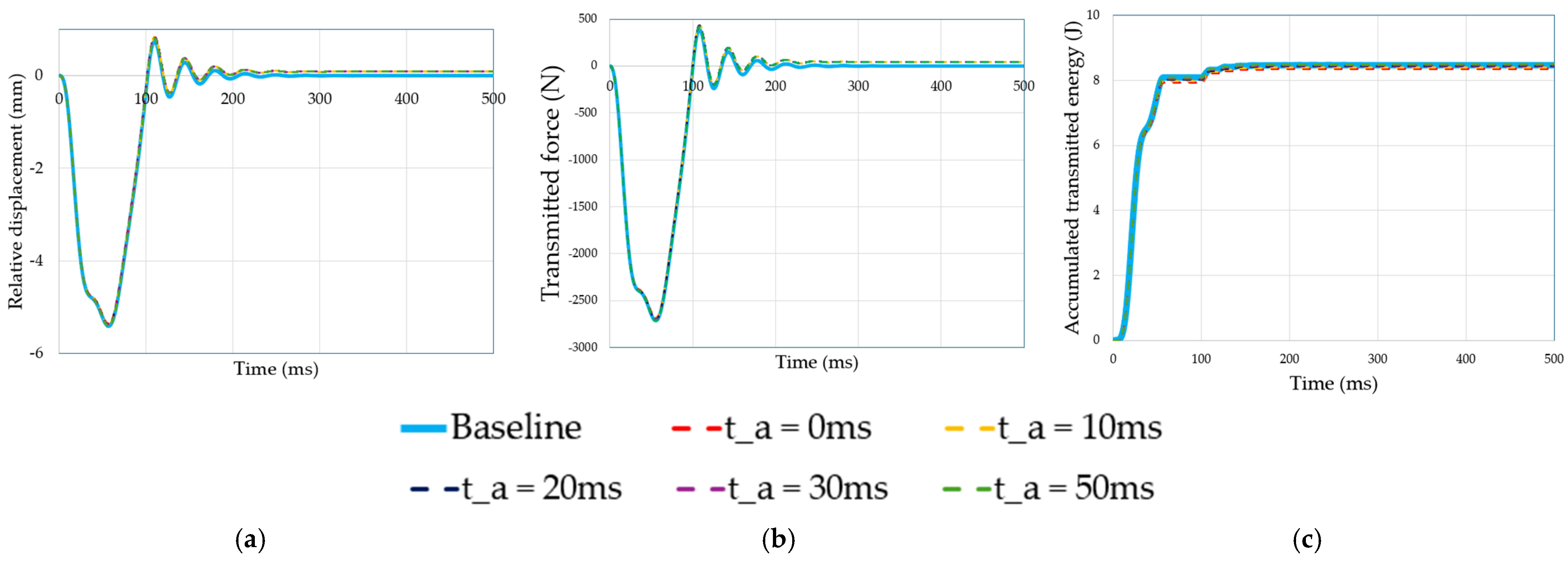
Figure 10 shows the computed response for the different activation delays in terms of relative displacement, transmitted force, and positive accumulated transmitted energy. The comparison shows that the mechanism effect decreases as activation is delayed because some relative motion has already developed before the rapid-response input starts.
Figure 10.
Effect of activation delay on the mechanism-enabled response: (a) relative displacement; (b) transmitted force; and (c) positive accumulated transmitted energy.
Table 6 summarizes the numerical results. For immediate activation, ta = 0 ms, the mechanism reduces maximum relative displacement by 0.99%, maximum transmitted force by 0.99%, and positive accumulated transmitted energy by 1.59%. When the activation delay increases, these reduction indices decrease. For ta = 50 ms, the positive accumulated transmitted energy becomes slightly higher than the baseline value, giving RE = −0.31%.
Table 6.
Effect of activation delay on the nominal mechanism-enabled response.
These results indicate that activation timing is a relevant parameter for the rapid-response mechanism. The mechanism is more effective when the repositioning input is introduced at the beginning of the event. Delayed activation reduces the mechanical effect and can eliminate the reduction in accumulated transmitted energy. The results therefore indicate that activation timing is a critical parameter. In practice, total activation delay includes crash detection, signal processing, triggering logic, communication, and actuator-command latency. These contributions are outside the scope of the present numerical model and should be quantified in future hardware and experimental studies.
3.4. Effect of Partial Mechanism Displacement
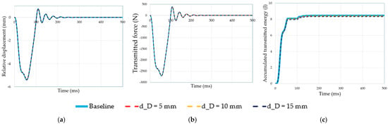
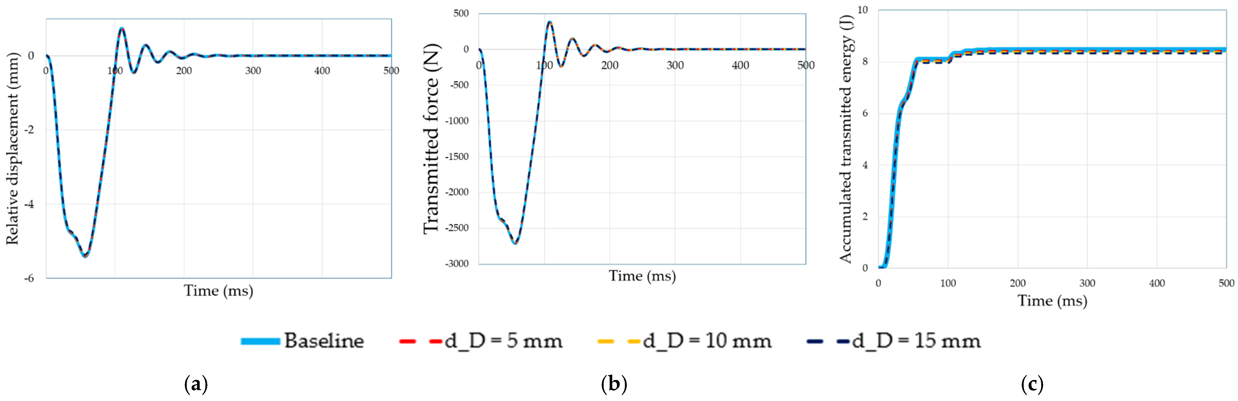
The effect of partial mechanism displacement is evaluated by varying the prescribed guided-slider displacement dD. The baseline case is kept unchanged, while the mechanism-enabled cases are calculated with dD = 5, 10, 15 mm. The value 15 mm corresponds to the mechanism’s maximum guided-slider travel, while 5 mm and 10 mm represent partial activation cases.
The same half-sine frontal-impact pulse is used in all cases, with Δv = 11.11 m/s and Timp = 0.1 s. Figure 11 shows the computed response for the different displacement cases in terms of relative displacement, transmitted force, and positive accumulated transmitted energy.
Figure 11.
Effect of partial mechanism displacement on the mechanism-enabled response for dD = 5, 10, and 15 mm: (a) relative displacement; (b) transmitted force; and (c) positive accumulated transmitted energy.
Table 7 summarizes the numerical results. The reduction indices increase with the imposed displacement. For dD = 5 mm, the reductions are 0.33% in maximum relative displacement, 0.33% in maximum transmitted force, and 0.53% in positive accumulated transmitted energy. For dD = 10 mm, the reductions increase to 0.66%, 0.66%, and 1.06%, respectively. The full activation case, dD = 15 mm, gives the largest reductions, with 0.99%, 0.99%, and 1.59%.
Table 7.
Effect of partial mechanism displacement on the mechanical performance indicators.
3.5. Effect of Stiffness, Damping, and Child Mass
The influence of the main dynamic parameters is evaluated by varying the equivalent child mass, equivalent stiffness, and damping ratio. These parameters modify the natural response of the equivalent child–seat dynamic model, since the natural frequency depends on the relation between k and m. Therefore, changes in these parameters affect the response to the prescribed rapid-response input.
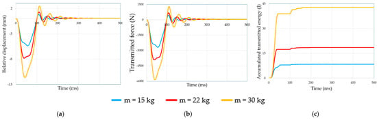
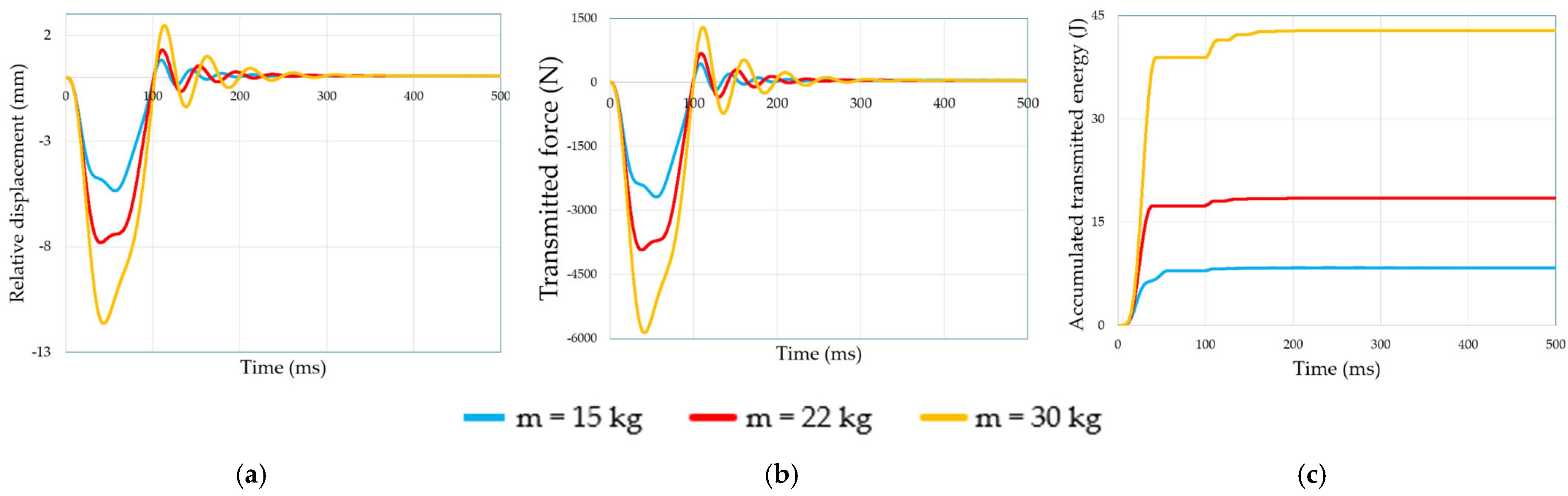
The equivalent child mass is varied as m = 15, 22, 30 kg according to the representative mass conditions defined in Section 2.7. We use the same half-sine frontal-impact pulse and nominal rapid-response condition in all cases. Figure 12 shows the computed response for the different mass values in terms of relative displacement, transmitted force, and positive accumulated transmitted energy.
Figure 12.
Effect of equivalent child mass on the mechanism-enabled response for m = 15, 22, and 30 kg: (a) relative displacement; (b) transmitted force; and (c) positive accumulated transmitted energy.
Table 8 summarizes the mass sensitivity results. Increasing the equivalent child mass increases the maximum relative displacement and the maximum transmitted force. However, the reduction indices decrease because the same rapid-response input has a lower relative effect when the equivalent inertia increases.
Table 8.
Effect of equivalent child mass on the mechanical performance indicators.
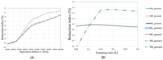
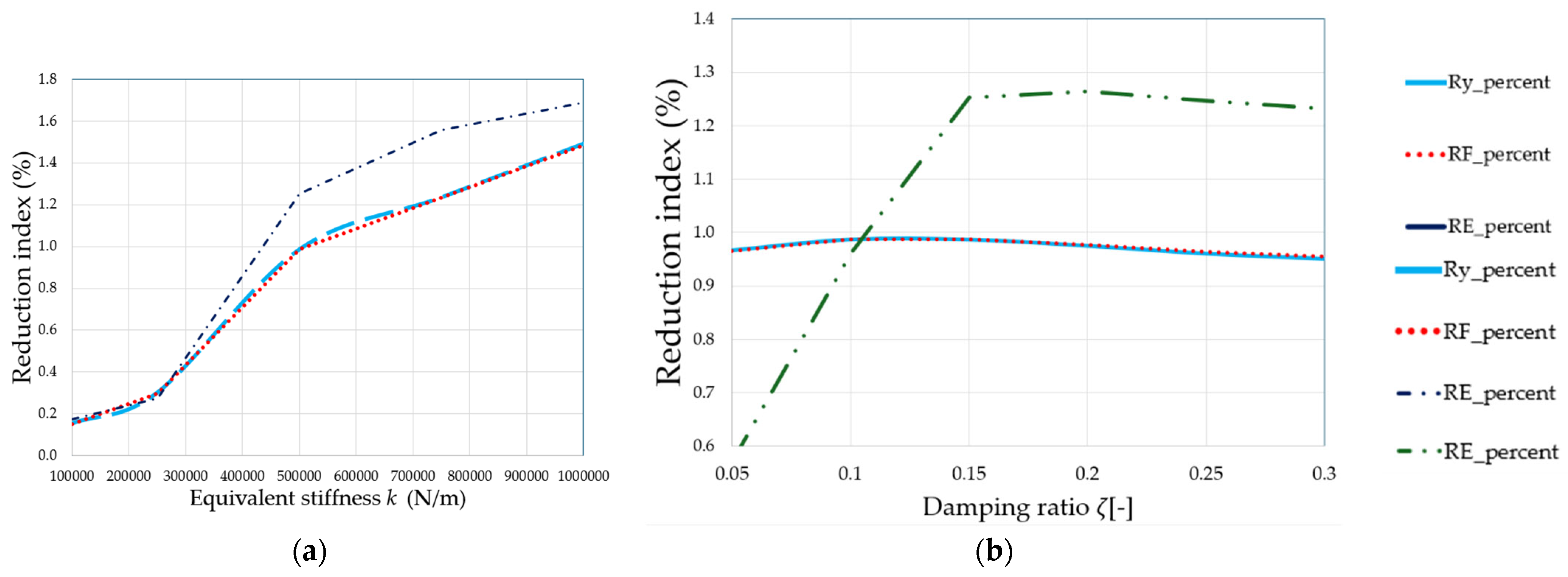
The equivalent stiffness is varied from 1 × 10⁵ to 1 × 10⁶ N/m, and the damping ratio is varied from ζ = 0.05 to 0.30. Figure 13 shows the corresponding mechanical performance indicators.
Figure 13.
Effect of dynamic parameters on the mechanical performance indicators: (a) equivalent stiffness and (b) damping ratio.
Table 9 summarizes the stiffness and damping sensitivity results. Higher equivalent stiffness generally increases the reduction indices, while the damping ratio mainly affects the positive accumulated transmitted energy. This confirms that the mechanism response is not determined only by the imposed displacement dD, but also by the dynamic properties of the equivalent child–seat model.
Table 9.
Effect of equivalent stiffness and damping ratio on the mechanical performance indicators.
The results show that the rapid-response mechanism has a stronger relative effect in stiffer equivalent systems. In contrast, damping produces only small changes in Ry and RF, but it modifies RE. The child mass also affects the response because it changes the inertia and the equivalent model’s natural behavior.
3.6. Summary of Mechanical Performance Indices
Table 10 summarizes the numerical results from Table 6, Table 7, Table 8, Table 9 and Table 10 to compare the main effects of the rapid-response mechanism under the evaluated conditions. The summary includes the nominal response, pulse shape, activation delay, partial displacement, child mass, equivalent stiffness, and damping ratio. The results show that the mechanism produces a measurable but moderate mechanical effect. The nominal half-sine case reduces maximum relative displacement by 0.99%, maximum transmitted force by 0.99%, and positive accumulated transmitted energy by 1.59%. The sensitivity analyses show that the response depends on the pulse profile, activation timing, guided-slider displacement, and dynamic parameters of the child–seat model. Table 11 presents a global summary of the main mechanical performance indicators.
Table 10.
Summary of the main mechanical performance indicators obtained from the numerical analyses.
Table 11.
Comparison between the present study and the authors’ previous works.
Overall, Table 11 confirms that the rapid-response mechanism should be interpreted as a repositioning device. Its effect depends not only on guided-slider displacement, but also on pulse shape, activation time, and the child–seat model’s equivalent dynamic properties.
4. Discussion
The numerical results show that the rapid-response linkage mechanism produces a measurable but moderate modification of the child–seat dynamic response. This aligns with the mechanism’s intended physical role. The actuator is not intended to absorb the global crash energy. Its function is to introduce a short repositioning input that modifies the child–seat system’s early kinematic condition.
This study represents a further stage in developing the proposed embedded CRS, building on the authors’ previous work. The EuCoMeS 2024 study addressed the integrated CRS concept and actuator-selection problem [26], whereas the subsequent Applied Sciences study focused on the mechanism architecture, CAD-based kinematic behavior, and actuator requirements [20]. The latter showed that a 15 mm actuator displacement completed in 0.1 s could produce an approximately 20° rapid backrest rotation, with an actuator requirement of approximately 150 mm/sand 490 N. These studies established the mechanism’s mechanical feasibility and design basis but did not evaluate the parametric baseline-versus-mechanism dynamic response considered here.
MEDER 2026 [30] subsequently reported a preliminary SDOF assessment. In that formulation, the mechanism contribution was introduced as an additional equivalent acceleration during the early crash phase, and it reported an approximately 20–25% reduction in the first transmitted-force peak. The present formulation should not be interpreted as a direct reproduction of those numerical values. Here, the mechanism motion is coupled explicitly to the one-dimensional response coordinate through the reduced-order formulation described in Section 2.5, and the energy-related response is evaluated using , which differs from the global transferred-energy quantity considered in the preliminary MEDER study. Under the nominal half-sine condition, the present model predicts reductions of 0.99% in maximum relative displacement, 0.99% in maximum transmitted force, and 1.59% in . The current study further extends the previous work by systematically examining pulse shape, activation delay, mechanism displacement, child mass, equivalent stiffness, and damping. Table 11 summarizes the comparison between the present study and the authors’ previous works.
The energy comparison supports this interpretation. Actuator work is small compared with both the vehicle kinetic energy and the child-related kinetic energy scale. Therefore, the mechanism must be treated as a local, time-dependent repositioning device. A reduction in transmitted force or positive accumulated transmitted energy should be interpreted as a change in the dynamic response, not as global impact-energy absorption. The interpretation of also requires caution. Because the transmitted power contains both recoverable spring-energy variation and viscous dissipation, the reported 1.59% reduction does not represent a 1.59% reduction in dissipated crash energy. It indicates only a lower positive accumulated mechanical-interaction measure within the reduced-order model. The actuator work is treated separately and should not be directly compared with this reduction index. The actuator requirements should also be interpreted within the limits of the prescribed-input formulation. The present model assumes that the required rapid-response motion can be imposed and does not include actuator force–velocity saturation, electromechanical dynamics, or load-dependent motion under crash-induced structural reactions. Consequently, the reported 490 N force and 0.236 m/s maximum prescribed velocity support a nominal mechanism-level feasibility assessment, but they do not demonstrate actuator performance under representative crash loading. A coupled mechanism–actuator analysis under dynamic loading is required.
The results also show that the mechanism response depends on the imposed impact pulse. Even with the same velocity change, different acceleration-time histories produce different responses. This confirms that pulse shape matters in the preliminary mechanical assessment of rapid-response CRS mechanisms.
Activation timing is another important factor. The mechanism is more effective when the rapid-response input is applied at the beginning of the event. Delayed input reduces the time available to modify early relative motion and can even eliminate the reduction in positive accumulated transmitted energy. This result is relevant for future sensing and control strategies. From an implementation perspective, ta = 0 represents an ideal upper-bound condition rather than an achievable zero-latency control response. A practical system would require crash detection, signal processing, triggering logic, and actuator-command execution, all of which introduce additional latency. The present numerical study does not determine the actual sensing and control delay; future hardware and experimental validation should establish it. Therefore, the delayed cases considered here are interpreted as parametric conditions used to quantify the sensitivity of the mechanical response to activation timing.
The sensitivity analysis confirms that the mechanism response is coupled with the child–seat model’s dynamic properties. Equivalent stiffness, damping ratio, and child mass modify the system response by changing how the impact pulse interacts with the model’s natural behavior. Therefore, the mechanism cannot be evaluated only by its maximum guided-slider displacement.
The present model’s sensitivity to stiffness and damping is consistent with the broader observation that mechanical and mechatronic dynamic elements can modify vehicle-seat response. However, unlike seat-suspension studies aimed at road-vibration isolation and ride comfort, the present analysis concerns a short-duration frontal-impact input and should not be interpreted as a vibration-isolation study.
The 1-DOF model represents only the dominant child–seat relative response in the principal impact direction. We evaluate the mechanism’s planar multi-link kinematics separately through the CAD-based analysis described in Section 2.2. We introduce the mechanism motion into the reduced-order model as a prescribed seat-side kinematic input. Therefore, this formulation suits the preliminary comparative analysis performed here but does not replace a fully coupled multibody model.
From a regulatory perspective, the proposed rapid-response mechanism’s potential utility can be considered against the principal child-restraint requirements used in major automotive markets. UN Regulation No. 129 [21] provides the main Enhanced Child Restraint System framework for UNECE markets, while FMVSS No. 213 [22] specifies child-restraint performance requirements in the United States. FMVSS No. 213a additionally introduces side-impact performance requirements for applicable child restraint systems [32]. In China, GB 27887-2024 sets mandatory requirements for child restraint systems [33], while GB/T 47246-2026 addresses technical requirements for electronic functions in child restraint systems [34].
The proposed mechanism may be relevant to these frameworks because it is intended to modify the early child–seat kinematic condition during a crash. Such repositioning may influence subsequent occupant excursion, restraint loading, dummy acceleration, and contact conditions. However, the mechanical indicators evaluated in this study are not regulatory injury criteria. Therefore, the present model’s predicted reductions cannot be interpreted as evidence of compliance with UN Regulation No. 129, FMVSS No. 213/213a, or GB 27887-2024. Demonstrating compliance would require testing the complete restraint system using the prescribed dummy, anchorage configuration, impact conditions, instrumentation, and acceptance criteria for each regulation.
The present frontal-impact model is therefore best interpreted as a preliminary design tool for identifying whether the rapid-response concept warrants subsequent regulatory testing. In particular, the current analysis does not address side-impact performance, which FMVSS No. 213a requires and which is also relevant to contemporary CRS approval frameworks. Future development should consequently include full-system frontal and side-impact evaluation under the applicable regional procedures.
For this reason, the results do not represent CRS certification, HIC reduction, Nij reduction, chest acceleration reduction, belt-load validation, or regulatory approval. Future validation requires experimental tests, instrumented child dummies, multibody simulations, finite-element models, and regulated dynamic test conditions.
5. Conclusions
This paper presented an energy-based numerical evaluation of a rapid-response linkage mechanism for an embedded child restraint seat. The mechanism was assessed as a rapid-repositioning device, not as a global crash-energy absorber or as a certified child restraint system.
The main contribution of this work is a dynamic framework to compare the baseline child–seat response with a mechanism-enabled response under equivalent frontal-impact pulses. The proposed indicators, based on relative displacement, transmitted force, and positive accumulated transmitted energy, quantify the mechanical effect of the rapid-response input during the early design stage.
The nominal case showed that the mechanism produces a measurable but moderate effect, reducing maximum relative displacement by 0.99%, maximum transmitted force by 0.99%, and positive accumulated transmitted energy by 1.59%. The sensitivity analyses showed that the mechanism response depends on pulse shape, activation timing, guided-slider displacement, equivalent stiffness, damping ratio, and child mass. Within the evaluated parameter range and under the assumptions of the equivalent one-dimensional child–seat model, the largest reduction indices were obtained for immediate activation and full 15 mm guided-slider displacement. These results should not be generalized beyond the modeling assumptions and parameter ranges considered in this study.
The results support using the proposed framework as a preliminary design tool for rapid-response CRS mechanisms. Future work should include prototype validation, instrumented dummy testing, multibody modeling, finite-element analysis, and regulated dynamic test conditions.
Author Contributions
Conceptualization, L.A.G.-H., M.C. and C.R.T.-S.; methodology, L.A.G.-H., M.C. and C.R.T.-S.; software, L.A.G.-H.; formal analysis, L.A.G.-H.; investigation, L.A.G.-H., M.C., A.R.-A. and C.R.T.-S.; resources, M.C. and C.R.T.-S.; data curation, L.A.G.-H.; writing—original draft preparation, L.A.G.-H.; writing—review and editing, L.A.G.-H., M.C., A.R.-A. and C.R.T.-S.; visualization, L.A.G.-H.; supervision, M.C. and C.R.T.-S.; project administration, M.C. and C.R.T.-S.; funding acquisition, M.C. and C.R.T.-S. All authors have read and agreed to the published version of the manuscript.
Funding
This research was supported by the Secretaría de Ciencia, Humanidades, Tecnología e Innovación (Secihti) and the Instituto Politécnico Nacional through project SIP-MULTI-2026-0023-M4 and the EDI grant, both administered by SIP/IPN.
Institutional Review Board Statement
Not applicable.
Informed Consent Statement
Not applicable.
Data Availability Statement
The datasets generated and analyzed during the current study are available from the corresponding author upon reasonable request.
Acknowledgments
The authors acknowledge the Instituto Politécnico Nacional, MEDER 2026 sponsored by IFToMM, and LARM2: Laboratory of Robot Mechatronics at the University of Rome Tor Vergata, for their academic and institutional support.
Conflicts of Interest
The authors declare no conflicts of interest.
References
- World Health Organization. Road Traffic Injuries; World Health Organization: Geneva, Switzerland, 2026; Available online: https://www.who.int/news-room/fact-sheets/detail/road-traffic-injuries (accessed on 14 October 2026).
- Peden, M.; Oyegbite, K.; Ozanne-Smith, J.; Hyder, A.A.; Branche, C.; Rahman, A.K.M.F.; Rivara, F.; Bartolomeos, K. (Eds.) World Report on Child Injury Prevention; World Health Organization: Geneva, Switzerland, 2008. [Google Scholar]
- Burdi, A.R.; Huelke, D.F.; Snyder, R.G.; Lowrey, G.H. Infants and children in the adult world of automobile safety design: Pediatric and anatomical considerations for design of child restraints. J. Biomech. 1969, 2, 267–280. [Google Scholar] [CrossRef] [Scilit] [PubMed]
- Arbogast, K.B.; Durbin, D.R.; Cornejo, R.A.; Kallan, M.J.; Winston, F.K. An evaluation of the effectiveness of forward facing child restraint systems. Accid. Anal. Prev. 2004, 36, 585–589. [Google Scholar] [CrossRef] [Scilit] [PubMed]
- Rice, T.M.; Anderson, C.L. The effectiveness of child restraint systems for children aged 3 years or younger during motor vehicle collisions: 1996 to 2005. Am. J. Public Health 2009, 99, 252–257. [Google Scholar] [CrossRef] [Scilit] [PubMed]
- Macy, M.L.; Lee, J.Y.; Kendi, S.; Zonfrillo, M.R.; Hill, A. Ease of Use ratings and real-world child restraint system errors from Safe Kids Illinois seat checks, 2015–2019. Traffic Inj. Prev. 2023, 24, 625–631. [Google Scholar] [CrossRef] [Scilit] [PubMed]
- European Commission. Road Safety Thematic Report: Seat Belt and Child Restraint Systems; European Road Safety Observatory: Brussels, Belgium, 2022. [Google Scholar]
- Sauber-Schatz, E.K.; West, B.A.; Bergen, G. Vital signs: Restraint use and motor vehicle occupant death rates among children aged 0–12 years—United States, 2002–2011. Morb. Mortal. Wkly. Rep. 2014, 63, 113–118. [Google Scholar]
- Muszyński, A.; Łuszczek, J.; Szymaniuk, R. Comparative analysis of child restraint systems safety parameters in relation to the New Regulation No. 129 of the Economic Commission for Europe of the United Nations (UN/ECE). Vehicles 2020, 2, 142–155. [Google Scholar] [CrossRef] [Scilit]
- Ning, D.; Sun, S.; Du, H.; Li, W.; Zhang, N.; Zheng, M.; Luo, L. An electromagnetic variable inertance device for seat suspension vibration control. Mech. Syst. Signal Process. 2019, 133, 106259. [Google Scholar] [CrossRef] [Scilit]
- Qiu, C.; Liu, X.; Shen, Y. Improvement of the Vehicle Seat Suspension System Incorporating the Mechatronic Inerter Element. World Electr. Veh. J. 2023, 14, 29. [Google Scholar] [CrossRef] [Scilit]
- Zhang, T.; Yang, X.; Shen, Y.; Liu, Y.; Wang, H.; Bi, S. A sky-hook positive real network based ISD seat suspension for commercial vehicle. J. Vib. Control 2026. OnlineFirst. [Google Scholar] [CrossRef] [Scilit]
- Noorsumar, G.; Rogovchenko, S.; Robbersmyr, K.G.; Vysochinskiy, D. Mathematical models for assessment of vehicle crashworthiness: A review. Int. J. Crashworthiness 2022, 27, 1545–1559. [Google Scholar] [CrossRef] [Scilit]
- Baranowski, P.; Damaziak, K.; Małachowski, J.; Mazurkiewicz, Ł.; Muszyński, A. A child seat numerical model validation in the static and dynamic work conditions. Arch. Civ. Mech. Eng. 2015, 15, 361–375. [Google Scholar] [CrossRef] [Scilit]
- Huang, M. Vehicle Crash Mechanics; CRC Press: Boca Raton, FL, USA, 2002. [Google Scholar]
- Rao, S.S. Mechanical Vibrations, 6th ed.; Pearson: Boston, MA, USA, 2017. [Google Scholar]
- Meirovitch, L. Elements of Vibration Analysis, 2nd ed.; McGraw-Hill: New York, NY, USA, 1986. [Google Scholar]
- Chopra, A.K. Dynamics of Structures: Theory and Applications to Earthquake Engineering, 4th ed.; Pearson: Upper Saddle River, NJ, USA, 2012. [Google Scholar]
- Inman, D.J. Engineering Vibration, 4th ed.; Pearson: Boston, MA, USA, 2014. [Google Scholar]
- Guerrero-Hernández, L.A.; Ceccarelli, M.; Torres-SanMiguel, C.R.; Russo, M. Problems and design of a powered mechanism-based car child restraint system. Appl. Sci. 2025, 15, 1402. [Google Scholar] [CrossRef] [Scilit]
- United Nations Economic Commission for Europe. UN Regulation No. 129: Uniform Provisions Concerning the Approval of Enhanced Child Restraint Systems Used on Board of Motor Vehicles; UNECE: Geneva, Switzerland, 2021. [Google Scholar]
- FMVSS No. 213; Federal Motor Vehicle Safety Standard No. 213: Child Restraint Systems. National Highway Traffic Safety Administration, U.S. Department of Transportation: Washington, DC, USA, 1971.
- SAE International. SAE J211-1: Instrumentation for Impact Test—Part 1: Electronic Instrumentation; SAE International: Warrendale, PA, USA, 2022. [Google Scholar] [CrossRef] [Scilit]
- Eppinger, R.; Sun, E.; Bandak, F.; Haffner, M.; Khaewpong, N.; Maltese, M.; Kuppa, S.; Nguyen, T.; Takhounts, E.; Tannous, R.; et al. Development of Improved Injury Criteria for the Assessment of Advanced Automotive Restraint Systems—II; National Highway Traffic Safety Administration: Washington, DC, USA, 1999. [Google Scholar]
- Takhounts, E.G.; Craig, M.J.; Moorhouse, K.; McFadden, J.; Hasija, V. Development of brain injury criteria (BrIC). Stapp Car Crash J. 2013, 57, 243–266. [Google Scholar] [CrossRef] [Scilit] [PubMed]
- Cruz-Jaramillo, I.L.; Torres-Sanmiguel, C.R.; Leal-Naranjo, J.A.; Martínez, L. Numerical child restraint system analysis in 6 years old infant during a dolly rollover test. Int. J. Crashworthiness 2021, 26, 404–412. [Google Scholar] [CrossRef] [Scilit]
- Cruz-Jaramillo, I.L.; Torres-Sanmiguel, C.R.; Cortes-Vásquez, O.; Martínez, L. Numerical low-back booster analysis on a 6-year-old infant during a frontal crash test. Appl. Bionics Biomech. 2018, 2018, 2359262. [Google Scholar] [CrossRef] [Scilit] [PubMed]
- Rueda-Arreguín, J.L.; Marco; Ceccarelli, M.; Torres-Sanmiguel, C.R. Design of an Articulated Neck to Assess Impact Head-Neck Injuries. Life 2022, 12, 313. [Google Scholar] [CrossRef] [Scilit] [PubMed]
- Guerrero-Hernández, L.A.; Torres-SanMiguel, C.R.; Flores-Campos, J.A.; Silva-Garces, K.N.; Ceccarelli, M. Performance Testing of an Integrated Car Child Restraint System. In New Trends in Mechanism and Machine Science. EuCoMeS 2024; Rosati, G., Gasparetto, A., Ceccarelli, M., Eds.; Mechanisms and Machine Science; Springer: Cham, Switzerland, 2024; Volume 165, pp. 37–45. [Google Scholar] [CrossRef] [Scilit]
- Guerrero-Hernández, L.A.; Ceccarelli, M.; Rojas Agustin, A.; Torres-Sanmiguel, C.R. A Performance Characterization of a Linkage-Based Child Seat. In Mechanism Design for Robotics. MEDER 2026; Gonçalves, R., Ceccarelli, M., Eds.; Mechanisms and Machine Science; Springer: Cham, Switzerland, 2027; Volume 214, pp. 83–90. [Google Scholar] [CrossRef] [Scilit]
- Guerrero-Hernández, L.A.; Torres-SanMiguel, C.R. Dispositivo de Retención Infantil Plegable Bajo Escenarios de Colisión Frontal. Registration No. MX/u/2022/000562. 2022; granted 9 September 2024.
- FMVSS No. 213a; Federal Motor Vehicle Safety Standard No. 213a: Child Restraint Systems—Side Impact Protection. National Highway Traffic Safety Administration, U.S. Department of Transportation: Washington, DC, USA, 2022.
- GB 27887-2024; Child Restraint Systems for Power-Driven Vehicles. Standardization Administration of China: Beijing, China, 2024.
- GB/T 47246-2026; Technical Specifications for Electrification of Child Restraint Systems for Power-Driven Vehicles. Standardization Administration of China: Beijing, China, 2026.

Disclaimer/Publisher’s Note: The statements, opinions and data contained in all publications are solely those of the individual author(s) and contributor(s) and not of MDPI and/or the editor(s). MDPI and/or the editor(s) disclaim responsibility for any injury to people or property resulting from any ideas, methods, instructions or products referred to in the content. |
© 2026 by the authors. Licensee MDPI, Basel, Switzerland. This article is an open access article distributed under the terms and conditions of the Creative Commons Attribution (CC BY) license.